

Page 1

MCN Server 8000 ™
Remote Comparator Display Software
for
Motorola Solutions IP Comparators
GCM 8000 Digital Comparator
&
MLC 8000 Analog Comparator
DDN1290
S2-61600-110
68-12286-110
Page 2

CTI Products, Inc.
1211 W. Sharon Rd.
Cincinnati, OH 45240
(513) 595-5900.
Information contained in this document is subject to change without notice and does not represent a
commitment on the part of CTI Products, Inc.
No part of this manual may be reproduced or transmitted in any form or by any means, electronic or
mechanical, including photocopying and recording, for any purpose without the written permission of
CTI Products, Inc.
Copyright 2004-2012 CTI Products, Inc. All rights reserved.
MCN, MCN Server 8000, MCNRCD, HIB-IP, HIB-IP 8000, CIB, AIB, TIB are trademarks of CTI
Products, Inc.
ASTRO, MOTOROLA, and MOTOROLA SOLUTIONS and the Stylized M Logo are trademarks or
registered trademarks of Motorola Trademark Holdings, LLC.
SNV-12 and JPS are trademarks or registered trademarks of Raytheon Company and are used for
reference.
Windows, Wind ows XP, Windows Vista, Windows 7, Windows Server 200x, Excel and Microsoft are
trademarks or registered trademarks of Microsoft Corporation and are used for reference.
Other trademarks referenced are properties of their respective owners.
2 68-12286-110
Page 3

LICENSED SOFTWARE NOTICE
The software described in this manual is subject to the:
MCN™ Server 8000 & Client Software License Agreement.
A copy of the above referenced License Agreement is i ncluded on the distribution media for this
software.
LIMITATION OF LIABILITY
IN NO EVENT WILL CTI OR ITS SUPPLIERS BE LIABLE FOR LOSS OF OR CORRUPTION TO
DATA, LOST PROFITS OR LOSS OF CONTRACTS, COST OF PROCUREMENT OF
SUBSTITUTE PRODUCTS OR OTHER SPECIAL, INCIDENTAL, PUNITIVE, CONSEQUENTIAL
OR INDIRECT DAMAGES ARISING FROM THE SUPPLY OR USE OF THE LICENSED
SOFTWARE, HOWEVER CAUSED AND ON ANY THEORY OF LIABILIT Y ( I NCLUDING
NEGLIGENCE). THIS LIMITATION WILL APPLY EVEN IF CTI OR AN AUTHORIZED
DISTRIBUTOR HAS BEEN ADVISED OF THE POSSIBILITY OF SUCH DAMAGES, EXCEPT TO
THE EXTENT THAT LIABILITY MAY NOT BY LAW BE LIMITED OR EXCLUDED, AND
NOTWITHSTANDING THE FAILURE OF ESSENTIAL PURPOSE OF ANY LIMITE D REMEDY.
IN NO EVENT SHALL CTI'S LIABILITY EXCEED ONE HUNDRED DOLLARS ($10 0 ) . YOU
AGREE THAT THE FOREGOING LIMITATIONS REFLECT A REASONABLE ALLOCATION OF
RISK.
CTI HAS NO CONTROL OVER THIRD PARTY CLIENT SOFTWARE AND MAKES NO
WARRANTIES OF ANY KIND FOR SUCH SOFTWARE. THE SUPPLIERS OF SUCH
SOFTWARE SHALL BE RESPONSIBLE FOR ANY SUCH WARRANTIES.
SOME STATES OR OTHER JURISDICTIONS DO NOT ALLOW THE EXCLUSION OR
LIMITATION OF LIABILITY FOR INCIDENTAL OR CONSEQUENTIAL D AM AGES, SO THE
ABOVE LIMITATIONS AND EXCLUSIONS MAY NOT APPLY TO YOU.
U.S. GOVERNMENT RESTRICTED RIGHTS
The Licensed Software and documentation thereto are deemed to be "commercial computer software"
and "commercial computer software documentation", respectively, pursuant to DFAR Section 227.7202
and DFAR Section 212.212, as applicable. Any use, modification, reproduction, release, performing,
displaying, or disclosing of the software or documentation by the U.S. Government shall be governed
solely by the terms of above referenced License Agreement and shall be prohibited except to the extent
expressly permitted by the terms of that Agreement. Any technical data provided that is not covered by
the above provisions is deemed to be "technical data-commercial items" pursuant to DFAR Section
227.7015(a). Any use, modification, reproduction, release, performance, display or disclosure of such
technical data shall be governed by the terms of DFAR Section 227.7015(b).
3 68-12286-110
Page 4

Revision History
S2-61600-105 Release for Production
S2-61600-106 Clarified Local Administrator vs. Active Directory Accounts
S2-61600-107 Added Server ID Selection in HW Setup (for IP comparators)
Added information on HIB-IP 8000 units with variable UDP Ports for
operation in an Astro™25 7.13 systems and above.
S2-61600-108 Added information about installation and re-installation sequences when used
with Windows Hardening Kit and McAfee Anti-Virus for Astro™25 7.13
systems and above.
Added information on Default Display Window (Display Screen).
Added permissible locations for HIB-IP units in an Astro™ 25 RNI.
S2-61600-109 Changed the IP Networking Considerations section to add PC location
restrictions for the Astro™ 25 RNI.
Added restriction on Dual-NIC operation in ASTRO®25 RNIs.
Added instructions to remove Ethernet ca ble from HIB-IP unit before
configuring it in MCN Config Server software.
S2-61600-110 Updated GCM 8000 BR/CM Pairing screen shot
Updated valid network locations for Server and HIB-IPs for A7.13 RNIs
Other minor oupdates.
4 68-12286-110
Page 5

Table of Contents
Table of Contents
INTRODUCTION ...................................................................................................................... 9
MANUAL STRUCTURE ............................................................................................................. 10
SHORTHAND NOTATION ......................................................................................................... 11
EXAMPLE SCREEN CAPTURES & EXAMPLE DATA .................................................................. 11
EXAMPLE SYSTEM DIAGRAMS ............................................................................................... 11
MCN SERVER 8000 IP SYSTEM EXAMPLE ............................................................................. 12
MCN SERVER 8000 IP AND LEGACY SYSTEM EXAMPLE ....................................................... 13
PACKAGE CONTENTS .............................................................................................................. 14
Software CD ..................................................................................................................................... 14
Hardware Key ................................................................................................................................... 14
Software Key CD .............................................................................................................................. 14
Software Manual ............................................................................................................................... 14
No PCs Included ............................................................................................................................... 14
REFERENCE DOCUMENTS ....................................................................................................... 15
Manuals for Motorola Solutions, Inc. Equipment ............................................................................. 15
Manuals fo r Legacy CTI Products MC N Equipment ....................................................................... 15
MCN SERVER 8000 PART NUMBERS ...................................................................................... 16
HARDWARE AND SOFTWARE ENVIRONMENTS ....................................................................... 16
Supported Operating Systems ........................................................................................................... 16
Security and Information Assurance Recommendations .................................................................. 17
Legacy Network Interfaces & Drivers .............................................................................................. 18
SOFTWARE INSTALLATION ............................................................................................. 20
INSTALLATION IN MOTOROLA SOLUTIONS, INC. ASTRO™25 SYSTEMS ................................ 20
RE-INSTALLATION OF IN MOTOROLA SOLUTIONS, INC. ASTRO™25 SYSTEMS ..................... 20
INSTALLATION OVERVIEW ..................................................................................................... 21
INSTALLING MCN SERVER SOFTWARE .................................................................................. 22
Customer Information Window ........................................................................................................ 23
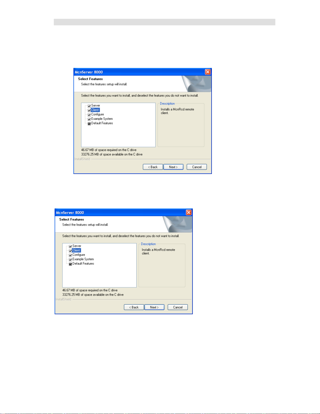
Selecting the type of installation ....................................................................................................... 23
Custom Installation ........................................................................................................................... 24
File Copying ..................................................................................................................................... 24
Hardware Key Driver Installation ..................................................................................................... 25
Completing the Installation ............................................................................................................... 25
Hardware Setup – HWSetup.exe ...................................................................................................... 26
Hardware Setup – HWSetup.exe ...................................................................................................... 26
MISCELLANEOUS INSTALLATION CONSIDERATIONS .............................................................. 35
Changing Set tin gs fo r your Legacy Network Interface .................................................................... 35
PC Power Options Setup ................................................................................................................... 36
Printer Installation ............................................................................................................................ 36
UNINSTALLING MCN SERVER SOFTWARE ............................................................................. 36
INSTALLING MCN CLIENT PROGRAM .................................................................................... 37
INTERFACING TO IP COMPARATORS ........................................................................... 41
GCM 8000 COMPARATOR INTERFACING ............................................................................... 41
Information needed about the GCM 8000 ........................................................................................ 41
GCM 8000 Subsite Assignment (BR/CM Pairing) Programmed in BR ........................................... 42
GCM 8000 Limitations ..................................................................................................................... 42
GCM 8000 Status Display ................................................................................................................ 43
MLC 8000 ANALOG COMPARATOR INTERFACING ................................................................. 44
Information needed about the MLC 8000 Analog Comparator ........................................................ 44
MLC 8000 Channel Cluster Tree ...................................................................................................... 44
MMC_Config.csv File -- MLC 8000 Analog Comparator Data ....................................................... 45
MLC 8000 Analog Comparator Data for multiple radio channels .................................................... 47
5 68-12286-110
Page 6

Table of Contents
MLC 8000 Analog Comparator CT Software Examples .................................................................. 48
MLC 8000 Analog Comparator Limitations ..................................................................................... 52
MLC 8000 Analog Comparator Status Display Tables .................................................................... 53
MM - MIXED MODE VOTING SOLUTION INTERFACING ......................................................... 55
Receiver (Subsite) Order for Mixed Mode Systems -- Very Important!........................................... 55
Mixed Mode System Limitations ...................................................................................................... 56
Mixed Mode Status Display ............................................................................................................. 57
Mixed Mode Tech Status Displays ................................................................................................... 58
INTERFACING TO LEGACY EQUIPMENT ..................................................................... 59
SYSTEM CONSIDERATIONS .............................................................................................. 60
IP NETWORKING CONSIDERATIONS ........................................................................................ 60
SOFTWARE CO-HABITATION AND PC LOCATIONS .................................................................. 60
HIB-IP CONSIDERATIONS ....................................................................................................... 61
DEFAULT SOFTWARE SETTINGS ............................................................................................. 61
WINDOWS ACCOUNTS ............................................................................................................ 61
PERMISSIONS FILE LOCATIONS & PERMISSIONS .................................................................... 62
CONFIGURING A SYSTEM - MCNCONFIG SERVER 8000 PROGRAM ................... 63
RESOURCE WINDOWS ............................................................................................................. 63
Resource Table Links ....................................................................................................................... 64
DISPLAY WINDOWS (STATUS SCREENS) ................................................................................ 65
EXAMPLE SYSTEM .................................................................................................................. 66
DEFAULT DISPLAY WINDOW .................................................................................................. 66
NAVIGATING THROUGH MCNCONFIG SERVER ...................................................................... 67
Controlli ng the Windows .................................................................................................................. 67
Screen Elements ................................................................................................................................ 68
Toolbars ............................................................................................................................................ 72
CONFIGURING SYSTEM RESOURCES ....................................................................................... 75
Adding IP Comparators & Network Interfaces - Network Interface Window .................................. 75
Configuri ng the Hardware - Hardware Resource Window ............................................................... 88
Configuri ng Radio Cha nnels - Channels Resource Window ............................................................ 92
Adding Receiver Data - Receivers Resource Window ..................................................................... 94
Building Screens -- Display Windo ws .............................................................................................. 99
Adding Receivers & I/O Groups to the Display Window ............................................................... 101
Using the Clipboard from other Applications ................................................................................. 116
MCNConfig Program: Client Permissions .................................................................................... 119
MCN SERVER 8000 PROGRAM ........................................................................................ 125
FIRST TIME SETUP ................................................................................................................ 125
Software Key .................................................................................................................................. 125
Selecting an Ethernet NIC to talk to the HIB-IP (and HIB-IP 8000) units ..................................... 126
Selecting an Ethernet NIC to talk to the MCN Client PCs ............................................................. 126
Windows Firewall ........................................................................................................................... 128
Setting IP Parameters ...................................................................................................................... 129
SCREEN ELEMENTS ............................................................................................................... 130
CONTROLLING THE MCN SERVER WINDOW ........................................................................ 130
Menus ............................................................................................................................................. 130
File Menu ........................................................................................................................................ 131
Options Menu ................................................................................................................................. 131
View Menu ..................................................................................................................................... 135
Help Menu ...................................................................................................................................... 140
DISPLAY ELEMENT PROPERTIES ........................................................................................... 141
MCN CLIENT PROGRAM .................................................................................................. 142
SELECTING IP PARAMETERS & SERVER LIST ....................................................................... 142
MAKING CONNEC TION WITH THE SERVER ........................................................................... 143
6 68-12286-110
Page 7

Table of Contents
SELECTING SCREENS ............................................................................................................ 144
FILE MENU ............................................................................................................................ 145
Open................................................................................................................................................ 145
Select Server ................................................................................................................................... 146
OPTIONS MENU ..................................................................................................................... 147
Font Window .................................................................................................................................. 147
IP Settings ....................................................................................................................................... 148
VIEW MENU .......................................................................................................................... 149
Layout Mode ................................................................................................................................... 149
CLIENT NORMAL RUN-TIME OPERATION ............................................................................. 150
Status Display ................................................................................................................................. 150
Control ............................................................................................................................................ 150
Multiple Tab Systems ..................................................................................................................... 150
CLIENT PROGRAM NOTES ..................................................................................................... 151
Data Loading & Cache Files ........................................................................................................... 151
Backup MCN Servers ..................................................................................................................... 151
IP Multicast Required ..................................................................................................................... 151
WINDOWS EVENT LOGGING .......................................................................................... 152
MCN CONFIG SERVER .......................................................................................................... 152
MCN SERVER 8000 .............................................................................................................. 152
CLIENTRCD .......................................................................................................................... 152
ADVANCED CONFIGURATION TOPICS – MCN CONFIG SERVER 8000 ............... 153
WORKING WITH DISPLAY TABLES ........................................................................................ 153
Display Table Properties W ind ow .................................................................................................. 154
States Tab........................................................................................................................................ 155
Mouse Actions Tab ......................................................................................................................... 162
Actions Tab – Used for Triggered Action and TPCI Licensed Options ......................................... 163
SubDevice Tab ................................................................................................................................ 164
Watchdog Tab – used with System Performance Toolkit licensed option ...................................... 164
CONFIGURING MASTER-SUB COMPARATOR SYSTEMS......................................................... 165
Configurati on Overview ................................................................................................................. 165
Virtual Comparator View ............................................................................................................... 167
IMPLEMENTI N G THE VIRTUAL COMPARATORS .................................................................... 169
Enable Master-Sub features ............................................................................................................ 169
Setup Network Interface, Channels, Hardware and Receiver windows .......................................... 170
Assign Display Tables and Define the SubDevices ........................................................................ 171
Design the Display Window for the Vir tual Comparator ............................................................... 172
Customizing Display Tables ........................................................................................................... 173
MASTER COMPARATOR DISPLAY TABLE ............................................................................. 174
CONFIGURING MASTER-SUB COMPARATOR WITH MULTI-DEPENDENCY ............................ 183
Composite Sub Comparator Display Table .................................................................................... 185
Multiple Views of the Virtual Co mparators.................................................................................... 186
Master Comparators ........................................................................................................................ 187
Multiple Views: Display Table Override ....................................................................................... 188
CONFIGURING TRIGGERED OUTPUT ACTIONS (LICENSED OPTION) ..................................... 192
Triggered Output Types .................................................................................................................. 192
Triggers ........................................................................................................................................... 196
Linking Inputs to Outputs ............................................................................................................... 198
Triggered Output Notes .................................................................................................................. 200
APPENDIX A: ERROR LOGGING DEFINITIONS ........................................................ 201
LOGGING TO A FILE .............................................................................................................. 201
Log File Location & Size ................................................................................................................ 201
LOGGING TO A PRINTER ........................................................................................................ 202
LOGGING TO THE PC SCREEN ............................................................................................... 202
7 68-12286-110
Page 8

Table of Contents
Error Logging Definition File Parameters ...................................................................................... 203
APPENDIX B: BACKUP & RESTORE PROCEDURES ................................................ 205
MCN SERVER AND CLIENT SOFTWARE BACKUP ................................................................. 205
MCN SERVER SOFTWARE KEY BACKUP .............................................................................. 205
CUSTOM MCN SERVER 8000 SYSTEM CONFIGURATION FILES BACKUP ............................. 206
HIB-IP SETTINGS BACKUP ................................................................................................... 206
MCN SERVER 8000 IP CONFIGURATION BACKUP................................................................ 207
MCN CLIENT IP CONFIGURATION BACKUP ......................................................................... 208
RESTORIN G THE MCN SERVER 8000 SOFTWARE & IP SETTINGS ........................................ 209
RESTORIN G THE CUSTOM SYSTEM CONFIGURATION FILES ................................................. 209
RESTORIN G THE HIB-IP CONFIGURATION ........................................................................... 209
RESTORIN G THE CLIENT SOFTWARE & IP SETTINGS ............................................................ 209
APPENDIX C: INSTALLING LEGACY PCLTA INTERFACE BOARD & DRIVER 210
LEGACY PCLTA NETWORK INTERFACE INSTALLATION ...................................................... 210
Install Legacy PCLTA Device Drivers (32 bit operating systems only) ........................................ 210
Install PCLTA Network Interface Card .......................................................................................... 211
Configure and Test the PCLTA Network Interface ........................................................................ 213
Cabling and Termination ................................................................................................................ 214
APPENDIX D: FIXING PCLTA INSTALLATION PROBLEMS .................................. 215
APPENDIX E: IMPORTING A SYSTEM FROM MCNRCD FOR DOS ...................... 216
IMPORTING THE SYSTEM ...................................................................................................... 216
Saving Imported Systems ............................................................................................................... 218
Imported Hardware Window .......................................................................................................... 219
Imported Receivers Window .......................................................................................................... 220
Imported Status Tables ................................................................................................................... 220
Missing MCF File s ......................................................................................................................... 221
Empty Status Table Entries ............................................................................................................. 221
FINISHING UP THE IMPORT .................................................................................................... 222
Display Window differences between the DOS and Windows programs ....................................... 222
APPENDIX F: LEGACY EQUIPMENT PART NUMBERS ........................................... 224
GLOSSARY ............................................................................................................................ 226
INDEX ..................................................................................................................................... 229
8 68-12286-110
Page 9

Introduction
Introduction
This manual c overs the installati on, configuration, and operatio n of the |
MCN Server 8000 and Client Software.
The MCN Server 8000 software can monitor and control the operation of the following t ypes of IP
comparators directly through an IP network:
• GCM 8000 Digital Comparators
• MLC 8000 Analog Comparators
• Mixed Mode Mixed Mode Voting Solution
GCM 8000 & MLC 8000 Analog Comparators
working together in Mi xed Mode s ys t ems
Since the MCN Server 8000 software is an enhanced version of the MCN Advanced Server, it maintains
the ability to monitor and control the following types of legacy equipment using components from the
MCN Monitoring and Control Network:
• Astrotac 3000 Digital Co mparators
• Digitac Comparators
• Spectra-TAC Analog Comparator
• SNV-12 Voter
• I/O and Alarm devices
The MCN Server 8000 will display receiver status indications such as:
• Vote
• Receive
• Disable
• Fail
It will also enable a user to control the following functions for the rece iver s
• Force-Vote
• Disable
9 68-12286-110
Page 10

Introduction
software
Software Installation
Installation of the software
Manual Structure
Major sections of the manual include
Introduction
Interfacing to IP Comparators
Interfacing to Legacy Equipment
System Conside r ations
Configuring a System - McnConfig
Server 8000 Program
MCN Server 8000 Program
MCN Client Program
Windows Event Logging
Advanced Configuration Topics –
MCN Config Server 8000
General discussion of the MCN Monitoring & Control
Network, system requirements for the MCN Server
Covers topics related to the GCM 8000, and ML 8000
comparators and mixed Mode systems
Connecting the MCN Server 8000 to legacy comparators
(Astrotac, Digitac, Spectra-T AC) and I/O d evices using
legacy MCN e quipment (HIB-IP or HIB-IP 8000 Modules,
CIB, AIB, GPIO Modules)
General system considerations including networking,
Windows accounts and file loc a tions & permissions
This is the largest part of the manual, because it describes
in detail all the system configuration features and options.
This cover s the operation of the MCN Server run-time
program.
This covers the operation of the MCN Client program.
Description of items logged in Windows Event Log
Customizing Display Tables, Master-Sub Comparators,
Triggered Output Actions
Appendix A: Error Logging
Definitions
Appendix B: Backup & Restore
Procedures
Appendix C: Installing Legacy
PCLTA Interface Board & Drive r
Appendix D: Fixing PCLTA
Installation Problems
Appendix E: Importing a System from
MCNRCD for DOS
Appendix F: Legacy Equipment Part
Numbers
Glossary
10 68-12286-110
Customizing the logging format for screen, disk, and
printer lo gging
Backup & Restore
Legacy PCLTA Network Interface board installation
Repairing errors in a PCLTA installation
(when installer didn't read the previous section)
Converting an old DOS MCN system
Part numbers for MCN equipment to interface to legacy
comparators and I/O devices
Page 11

Introduction
Shorthand Notation
The manual may refer generically to "MCN Server" or "MCN Server Software" or simply "Server
software" to refer to the MCN Server 8000 software.
RCD stands for "Remote Comparator Display".
The manual will refer to other pr ograms in a shorthand notation:
Program Shorthand Executable file name
Hardware Setup HWSetup Hardware Setup Server.exe
Configurati on Progr am MCN Config McnConfig Server 9000.exe
Server Program MCN Server MCN Server 8000.exe
Client Program MCN Client ClientRcd.exe
This manual may refer to Motorola Solutions, Inc. as simply "Motorola".
Example Screen Captures & Example Data
Example screen captures of the various progra ms are shown t hrough the manual to give the reader an
example of what to expect during setup, confi guration, and operati on of the software. Newer versions of
the software may include updated windows with slightly different wording or additional fields.
Data shown in example screen captures is presented only for example purposes only. It does not reflect
any particular user's system.
Various sections of the manual focus on particular topics. Example screen captures within a section are
presented as examples of the topics covered in that section. Example data show in the screen captures in
one section may not apply to screen captures shown or system configuration described in different
sections.
IP Addresses, Sub net Masks, Gate way IP Addresses, UDP port numbers, AGU and VGU IDs shown in
the manual are intended to show the appropriate linkages between IP Comparators, AGU Receiver Ports,
HIB-IP or HIB-IP 8000 Units, Clients , and Serve r PCs. They are taken from test systems in a lab and
are used as examples only. They will not reflect your system settings. They should not be taken as
recommendations.
Since the test system used in prep aring this manual did not include the various IP routers u sed in an
ASTRO® 25 7.x system, the example settings do not coincide with the requirements and
recommendations of Motorola's IP Plan. Each system is different; refer to the documentation for your
system for the proper IP addresses and UDP port numbers.
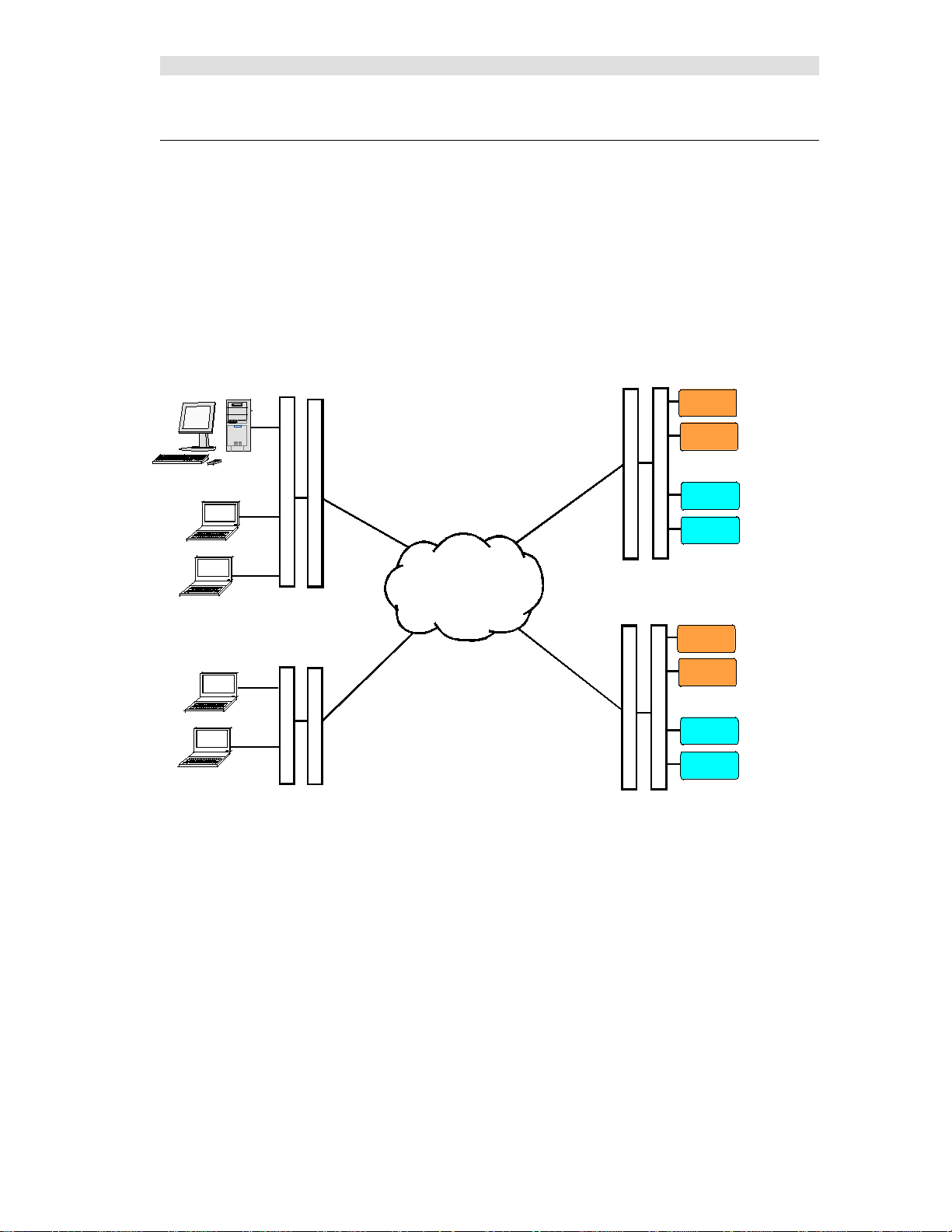
Example System Diagrams
System diagrams in this manual a re included to illustrate example gener a liz e d systems and principles
and are not intended to reflect any particular system configuration. In particular, a simplified IP
infrastructure is shown. Real-world IP networks (especially Astro® 25 Radio Network Infrastructures
(RNIs) may include additional r outers, gateways, switches, etc.
11 68-12286-110
Page 12
Introduction
MCN SERVER PC
MLC 8000
VGU
GCM 8000
GCM 8000
IP SwitchRouter
Remote Site 1
GCM 8000
GCM 8000
IP Switch
Router
Remote Site N
DISPATCH 1
DISPATCH 2
WAN
MCN CLIENT PCs
CA-80927-101
RouterIP Switch
MLC 8000
VGU
MCN CLIENT PCs
Router
IP Switch
VGU
VGU
MLC 8000
MLC 8000
MCN Server 8000 IP System Example
A typical MCN Server 8000 PC is shown in the figure below attached Motorola IP Comparators.
The MCN Server 8000 Remote Comparator Display system consists of:
An PC running the MCN Server 8000™ program
One or more Motorola Solutions IP Comparators
(GCM 8000 or MLC 8000)
Client PCs connected to the PC over an IP LAN or WAN.
Figure 1 – MCN Server 8000 System with IP Comparators
• The diagram includes o nly the IP comparators and not legacy equipment.
• The diagram does not show the BRs (Base Radios) or the
MLC 8000 Subsite Link Converter (AGU) units.
• Other IP routes and switches may be involved.
• The GCM 8000 and MLC 8000 Analog Comparators can be operating in a stand-alone mode (4
digital and 4 analog channels) o r they could b e operating as a Mixed Mode Voting Solution (4
Mixed Mode channels) or a combination of stand-alone and Mixed-Mode channels.
• The MCN Server 8000 PC is a stand-alone PC. It does not need Windows Server software.
• Client PCs may be st and-alone PCs or may be MCC 7500 Dispatch PCs running the MCN
Client software.
12 68-12286-110
Page 13
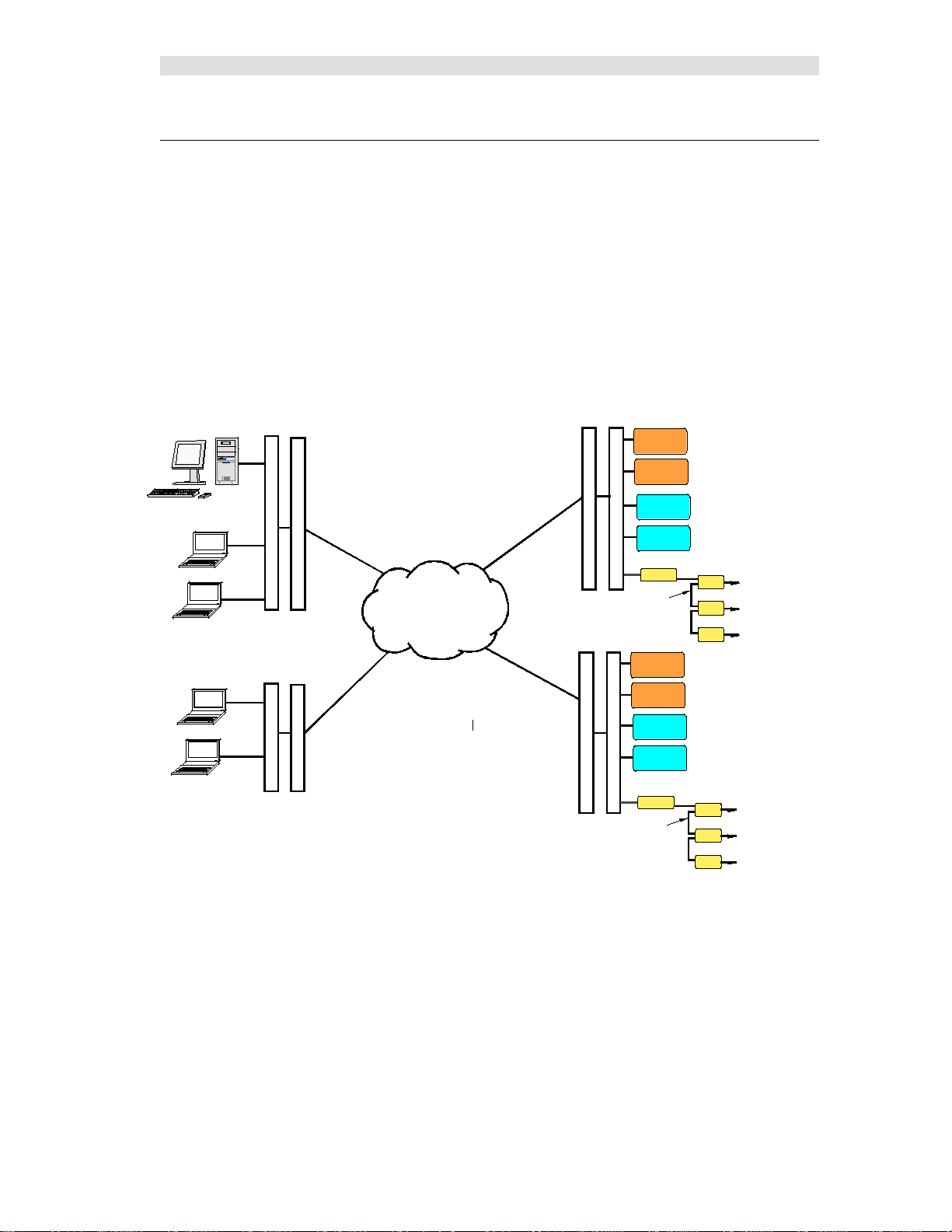
Introduction
MCN SERVER PC
MLC 8000
VGU
GCM 8000
GCM 8000
IP SwitchRouter
Remote Site 1
GCM 8000
GCM 8000
IP Switch
Router
Remote Site N
DISPATCH 1
DISPATCH 2
WAN
MCN CLIENT PCs
CB-80927-101
RouterIP Switch
MLC 8000
VGU
MCN CLIENT PCs
RouterIP Switch
VGU
VGU
MLC 8000
MLC 8000
MCN
To Digitac Comparator
To Astrotac Comparator
To Alarms Points & I/O
Network
Legacy Eqpt
HIB-IP
CIB
AIB
GPIO
MCN
To Digitac Comparator
To Astrotac Comparator
To Alarms Points & I/O
Network
Legacy Eqpt
HIB-IP
CIB
AIB
GPIO
MCN Server 8000 IP and Legacy System Example
The MCN Server 8000 software is an extension of C TI Products' legacy M CN (Monito ring and Control
Network) software packages. It retains the ability to support legacy MCN equipment and legacy
comparators. For legacy systems, the following optional items may be present:
One or more network interfaces for the MCN Server PC
(such as a HIB-IP OR HIB-IP 8000, internal PCLTA or HIB-232)
One or more Comparator I/O Modules (such as an AIB or CIB)
Other interface modules (such as IOB or GPIO Mod ules) to drive auxiliary outputs and alarms
The following diagram shows a syst em that supports both the IP comparators and legacy comparators.
Figure 2 – MCN Server 8000 System with IP & Legacy Comparators
• This diagram shows the addition of MCN modules to support legacy equipment.
• The HIB-IP 8000 units connect to the MCN Network at the remote sites.
• The CIB, AIB, and GPIO Modules connect to the legacy comparators and I/O points.
• The IP comparators and legacy equipment can be displayed on the same screens.
13 68-12286-110
Page 14

Introduction
Package Contents
The MCN Server 8000 package will include the following:
Software CD
The MCN Server 8000 software package includes:
Installation Program
This is a standard Installshield program used to install the software o n the PCs.
The CD has both the MCN Server 8000 and the MCN Client software on it.
HWSetup Program
This is used to select which network Inter faces to use for legacy support.
It is also used to enter the Software Key for the system.
MCNConfig Program (McnConfig Server 8000.exe)
This is the configuration program tha t is used b y an engineer or technician to build the
configuration files when the system is installed or changed.
MCN Server 8000 Program
This is the program that operates on the MCN S erver PC. It has a local display that displays the
status of the devices on the MCN syste m (Comparators, I/O points, alarms, etc.). It allows the
operator to control receivers (with Force-Vote and Disable functions) and other I/O devices
(relays, etc.) from the MCN Server PC.
The MCN Server program also passes the status and control data to MCN Client PCs over an IP
LAN or WAN.
MCN Client Program (ClientRCD.exe)
This is the Client program that operates on remote PCs to control and display the status of the
MCN system. The MCN Client program operates on PCs connected to the MCN Server via a n IP
network, and thus do not need their own MCN Ne twork Interface.
Manuals in PDF for mat
Hardware Key
A serialized USB Key is included.
Software Key CD
This CD will have the Software Key for the system. The Software Key matches the serial number of
the Hardware Key. It will contain the capabilities licensed for the software (number of IP
comparators, number of clients, etc.)
Software Manual
This manual.
No PCs Included
The MCN Server 8000 software package does not include Server or Client PCs.
14 68-12286-110
Page 15

Introduction
Reference Documents
Manuals for Motorola Solutions, Inc. Equipment
Information on the Motorola IP Comparators can be found in the documents available from Motorola
Solutions for your system. The following is a list of manuals that may apply to your system. There may
be additional manuals that may apply. Be sure to use the proper version of the manual for your system's
version.
GCM 8000 Comparator Manual
MLC 8000 Comparator Manual
Quick Guide for Implementing MLC 8000s
MLC 8000 C onfiguration Tool with Analog Display and Control manual
Conventional Operations manual
GTR 8000 Base Radio Manual
Information Assurance Features Overview manual
MCC 7500 Dispatch Console with VPM manual
System LAN Switches manual
System Gateways – GGM 8000 manual
Authentication Services
Windows® Supplemental CD and the corresponding ASTRO 25 system Windows Supplemental
Configurati o n ma n ual
Manuals for Legacy CTI Products MCN Equipment
Details of other legacy hardware components of the system can be found in the following documents:
S2-60425 Monitoring and Control Network, System Manual
S2-61173 HIB-IP & HIB-IP 8000 Remote Network Interface Hardware Reference Manual
S2-60427 HIB-232 Host Computer Interface Module, Hardware Reference Manual
S2-60426 CIB Comparator I/O Module, Hardware Reference Manual
S2-60399 AI B As t r o tac Comparator Interface Module, Hardware Reference Manual
S2-60630 IOB I/O Control Module, Hardware Reference Manual
S2-60596 EXB-232 and EXB-IM Network Extender Modules, Hardware Reference Manual
S2-61089 EXB-IP and EXB-FI Network Extender Modules, Hardware Reference Manual
S2-60649 MCN Router Modules, Hardware Reference Manual
15 68-12286-110
Page 16

Introduction
Number
Part Number
Description
DDN1289
S1-61594
MCN SERVER 8000 SW LIC FOR 4 MOTOROLA IP COMPARTORS & 4 CLIENTS
DDN1287
S1-61595
MCN SERVER 8000 SW LIC OPT FOR 1 ADD'L MOTOROLA GCM 8000 OR MLC 8000
DDN1288
S1-61596
MCN SERVER 8000 SW LIC OPT FOR 4 ADD'L MOTOROLA GCM 8000 OR MLC 8000
DDN1295
S1-61129
MCN SW LIC OPT CLIENT EXPANSION FOR 4 ADD'L CLIENTS
DQS261151
S2-61151
MCN HIB-IP 8000 UNIT FOR LEGACY MCN NETWORKS
MCN Server 8000 Part Numbers
The following part numbers are for the MCN Server 8000 software and options.
Legacy MCN equipment part numbers appear in the Appendix F: Legacy Equipment Part Numbers
section on page 224.
Motorola
Part
CTI Products
DDN1294 S2-61164
DDN1290 S2-61600 MCN SERVER 8000 MANUAL
MCN SW LIC OPTION MULTI-NI-4. ADDS SUPPORT FOR (4) HIB-IP
(or HIB-IP 8000) Units
Hardware and Software Environments
MCN Server 8000 and Client software requires a PC with th e following minimum system config ura tion:
Windows XP, Vista, or 7 or Windows Server 2003, 2005, 2008R2
The MCN Server software does not need to be run on a Windows Server operating system.
Intel 64-Bit processor 2.0 GHz (Xeon Dual-Core W3503 recommended)
2 GB Memory
CD-ROM Drive
Open USB 2.0 Port
100Base-T Ethernet port
One open serial port if the local network interface is a HIB-232
One open PCI slot if a legacy MCN PCLTA Network Interface card is used
(only for 32-bit operating systems)
Color Monitor
Supported Operating Systems
In a stand-alone system, the MCN Server software and the Client software can run on:
• Windows XP
• Windows Vista
• Windows 7
• Windows Server 2003
• Windows Server 2005
• Windows Server 2008r2
16 68-12286-110
Page 17

Introduction
Recommended Software
It is recommended that Adobe Acrobat Reader be installed on the system to provide access to the
manuals in P DF format from Windows and from the Help menu.
ASTRO® 25 7.12 & 7.13 Certification
The software is certified for use in an ASTRO® 25 Ver 7.12 & 7.13 system for the following operating
systems:
• Windows 7, 64 Bit
Follow all of Motorol a's Networki ng, Information Assurance, Hardening and other system require ments
and recommendations for use on ASTRO® 25 7.12 & 7.13 systems.
NM Client & MCC 7500 Console Cohabitation
The Client software is certified to be installed and co-habit with NM Clients or MCC 7500 consoles. It
can also be installed on a stand -alone PC.
Security and Information Assurance Recommendations
Review these recommendations before installation and follow them during inst allation and opera tion:
1. Software Installation Locations
Install the software in default program directory recommended by Install-shield.
2. Configure the MCN Server 8000 and MCN Client software as described in this manual. If
applicable, take into consideration commercially accepted practices, industry standards and the
standards for your or ganization.
3. Do not save user files or sys t em configuration files in the program directory.
4. Save system configuration files to a directo ry that requires Administrator ri ghts so that users
cannot delete or edit the configuration files. See the Windows Accounts section on page 61 for
additional information.
5. Always run the software with the lowest permission set possible.
Run both the MCN Server 8000 and the MCN Client software with User rights, not
Administrator rights. See the Wi ndows Accounts sect ion on p age 61 for a dditional
information. (Note: To initially configure the MCN Ser ver List or change the MCN Server List
for the MCN Client software, you will need to run MCN Client with Administrator rights once.
For subsequent opera tion, run it with User rights.)
6. When configuring a system, d o not enter Sensitive or Confide ntial in formation into the system
configuration files.
7. The MCN Server 8000 software, the MCN Client software and system configuration files are
not backed up as part of the ASTRO® 25 Back UP & Restore (BAR) solution. Follow the
Backup & Recovery procedures as listed in Appendix B: Backup & Restore Procedures on
page 205 for the MCN Server 8000, MCN Client, and system configurati on data. The
procedures in the Appendix apply only to this software and do not back up or restore part of the
ASTRO® 25 system.
8. Follow the applicable Backup & Recovery procedures for your system, PCs, and operating
systems as defined by your organization, the hardware and software vendors, and commercially
acceptable practices.
9. Limit access to PCs
10. Limit access to networks, both physically and through appropriate restrictions in routers and
switches
11. Use strong passwords
17 68-12286-110
Page 18

Introduction
12. Follow Motorola's and your organization's recommendations on security and Information
Assurance.
13. Use the appropriate Windows Hardening Kits for your installation
14. Use anti-virus and anti-malware packages
15. Install appropriate security patches for installed software and operating system
16. The MCN Server is not a syslo g client. Event logging is done locally to the MCN Server. See
Windows Event Loggin g and Appendix A: Error Logging Definitions sections for details.
17. The Back up & Restore (BAR) procedures in this manual are for the MCN Server 8000 system.
18. Use of multiple NIC cards (Dual-Home systems) is not approved by MSI in ASTRO® 25 RNIs
due to Information Assurance (IA) security c oncerns.
Local Administrator versus Active Directory Accounts
Some of the operations described in this manual require Administrator rights.
Log
on either as the local Windows administrator, or using your Active Directory account that is a
member of the group “cti-login” with authority to access this device. The
account set up by Motorola for Windows 7-based devices is
“secmoto”.
local Windows administrator
NOTE: Active Directory account login is recommended, if available.
Legacy Network Interfaces & Drivers
Three general categories of MCN Network Interfaces are used with MCN Server program to support
legacy MCN systems:
HIB-IP External Modules For connection to MCN 78K networks over IP networks
Legacy Units: Version 110 - 399
The Legacy HIB-IP unit(s) can be local or remote.
Legacy units are not certified for use across Astro™25 RNIs.
HIB-IP 8000 Version 400 & higher:
These versions are for use across Astro™25 RNIs.
HIB-232 External Modules Version 200 & Up 78K
(with Rotary address switches on back)
For RS-232 connection
(Although t he HIB-232 manual talks about dial-up operation,
the MCN Server 8000 program does not support dial-up
operation of the HIB-232.)
Internal Boards PCLTA-21 Half-Size PCI Board 78K or 1250K versions
For direct connection to the MCN Network
Supported only by 32-bit operating systems.
(Also supports connection to remot e networks using EXB
Network Extender Modules)
18 68-12286-110
Page 19

Introduction
Legacy Drivers for MCN Server
The PCLTA Interface boards need a software driver to run the MCN Server program.
This will be included with the PCLTA & software package. This drive is only available for 32bit operating systems.
The HIB-IP and HIB-232 modules do not need a driver for normal operation of the MCN Server
program.
19 68-12286-110
Page 20

Installation
Software Installation
Installation in Motorola Solutions, Inc. Astro™25 Systems
PCs installed in a Motorola Solutions, Inc. (MSI) Astro™25 system must have (among other things) the
following items installed:
• Windows Hardening Kit
• Anti-Virus (For Astro™ 7.13 and above systems, the anti-virus syste m used is:
McAfee EndPoint Software
The proper order for software installation is:
1. Install the Windows Operating System (if not re-installed).
See instruct i ons in appropriate MSI document.
2. Perform the Operating System Initialization Steps.
See instructions in appropriate MSI document.
3. Install the Motorola Solutions Inc. Wind ows Hardening Kit.
See instructions in appropriate MSI document.
4. Install MOTOPATCH.
5. Install the MCN Server 8000 and/or Client software as described in the following sections of
this manual.
6. Install the McAfee EndPoint Software.
See instructions in appropriate MSI document.
Re-Installation of in Motorola Solutions, Inc. Astro™25 Systems
If you need to re-install the software or an update, the proper order for is:
1. Normally, you should be able to re-install the software without un-installing McAfee Endpoint
Software or disabling functions in it. However, that might chan ge with diffe rent configurations.
If you have difficulty installing the CTI software, try turning off the virus protection. If that
fails, try un-installing McAfee .
2. Remove the CTI software
3. Install the MCN Server 8000 and/or Client software as described in the following sections of
this manual.
4. Re-enable or re-install McAfee Endpoint Software if it was disabled or removed in an earlier
step.
20 68-12286-110
Page 21

Installation
Installation Overview
Prior to installation, please read the System Considerations sectio n o f this manual starting on page 60.
The installation of the MCN Server software and network interfaces are done in the following order:
If you have legacy MCN equipment and will use a PCLTA network interface
(32-bit Windows only), install the PCLTA device drivers and network interface card, then test the
interface. See Appendix C: Installing Legacy PCLTA Interface Board & Driver on Page 210.
1) Run setup.exe on the MCN Server PC to install t he MC N Server software. .
See Installing MCN Server Software on page 22.
2) Gather the information on your s ystem.
For IP comparators, see Interfacing to IP Comparators on page 41
For systems with Legacy Comparators or I/O devices, see Interfacing to Legacy Equi pment on page
59.
3) Run the MCN Config Server program (see page 41.) to build your system resources l ists for:
Network Interfaces (Legacy syste ms )
Legacy: PCLTA, HIB-IP, HIB-IP 8000, HIB-232
Hardware Modules (IP & Legacy):
IP: GCM 8000, MLC 8000, Mixed Mode
Legacy: CIB, AIB, GPIO
Channel Names
Receiver Names, I/O Points & other data.
You will probably not need to edit the Display Tables unless you need to change the display colors
and text for the receiver status displays.
4) Use MCN Config Server program to build your Display Screen(s) by:
Placing receivers & I/O points on screens
Adding channel labels
Adding tabs if required
5) Use MCN Config Server program to build a list of Client Authorizations if required to limit access
of certain clients to certain display screens
6) I f you have Legacy MCN eq uipment and are using HIB-IP or HIB-IP 8000 units, program them
using MCNConfig program. See Programmin g HI B -IP and HIB-IP 8000 Units on page 86.
7) Install the Security Hardware Key in a US B slot on the MCN Server PC.
8) Run the MCN Server program on the MCN Server PC. See MCN Server 8000 Program on page
125. You will be asked to enter the MCN Software Key and IP parameters on the first use.
9) Run setup.exe on the MCN Client PCs to install the MCN Client program. See Installing MCN
Client on page 37 for details.
10) Run the MCN Clie nt program on the Client PC(s). See MCN Client Program on page 142.
21 68-12286-110
Page 22
Installation
Installing MCN Server Software
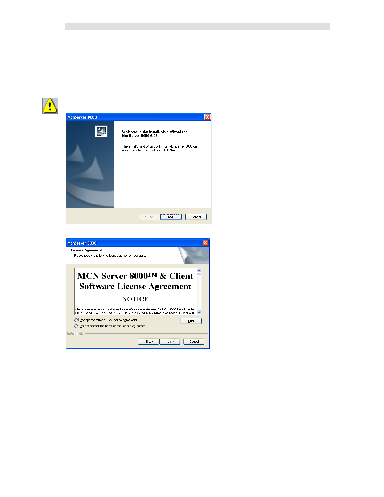
Run Setup.exe from the CD.
You must have Ad mini st ra to r right s to in stall the MCN Server software.
Read the License Agreement.
If you agree to the terms, click the "I Accept…" button as shown above a nd then hit the Next button to
continue toe installation.
22 68-12286-110
Page 23
Installation
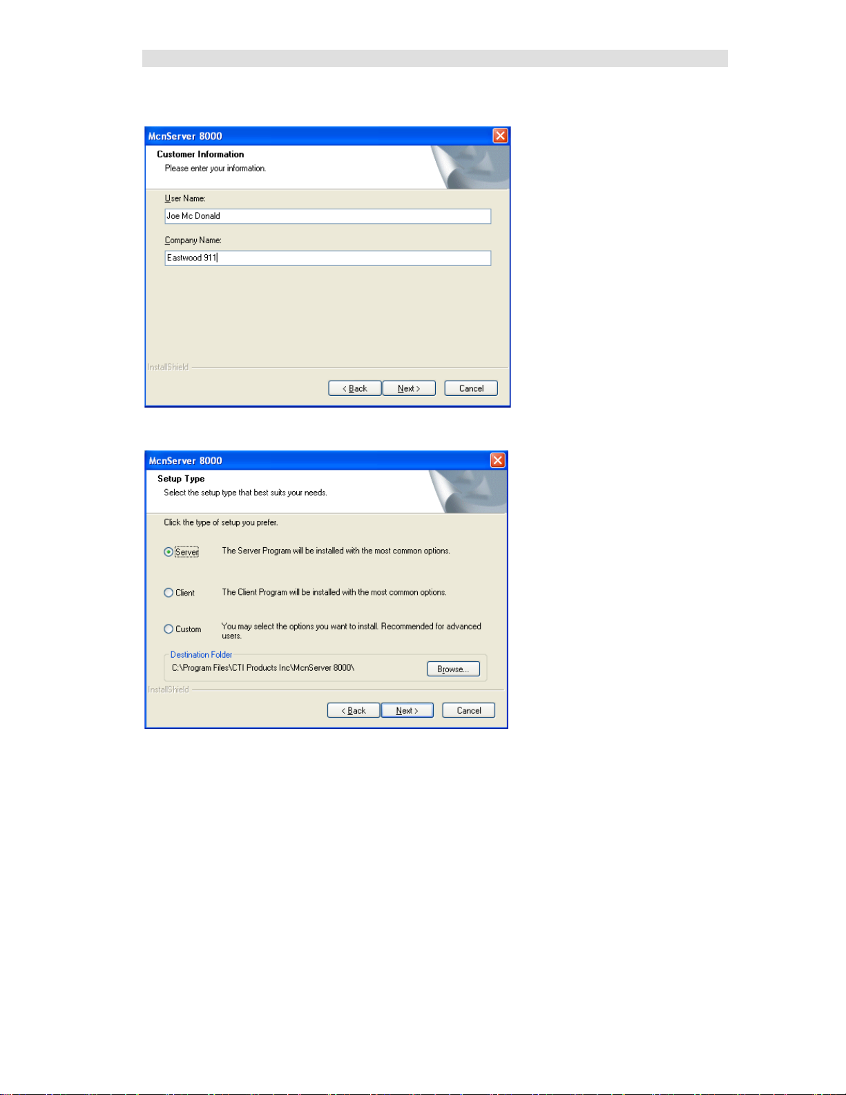
Customer Information Window
Selecting the type of installation
If you choose the custom installation, you can install both the MCN Server and the MCN Client
programs on your PC.
23 68-12286-110
Page 24
Installation
Custom Installation
If the "Custom" option is shown, the following window is displa yed.
(If the "Custom" option is not chosen, this step is skipped.)
You can install the Client software on the Server PC.
After selecting the desired options, select Next.
File Copying
Confirm the settings and hit Next.
24 68-12286-110
Page 25
Installation
Hardware Key Driver Installation
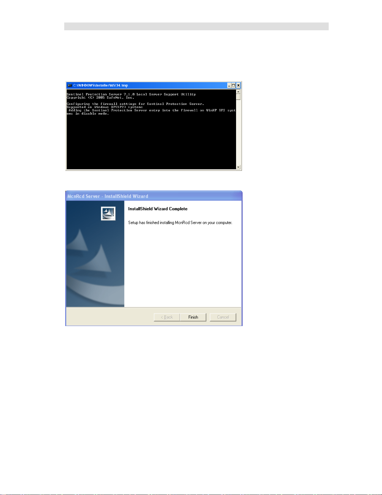
The driver software for the Hardware Key will be installed automatically.
The process may be so quick that you don't even see the installation process.
Completing the Installation
Click Finish.
Remove the C D.
This finished the software installation.
25 68-12286-110
Page 26
Installation
Hardware Setup – HWSetup.exe
The Hardware Setup program is used to enter the Software Key and inform the programs which types of
Network Interfaces (IP Comparators, HIB-IP units, or Non-Dial-up HIB-232 units) will be used in the
system.
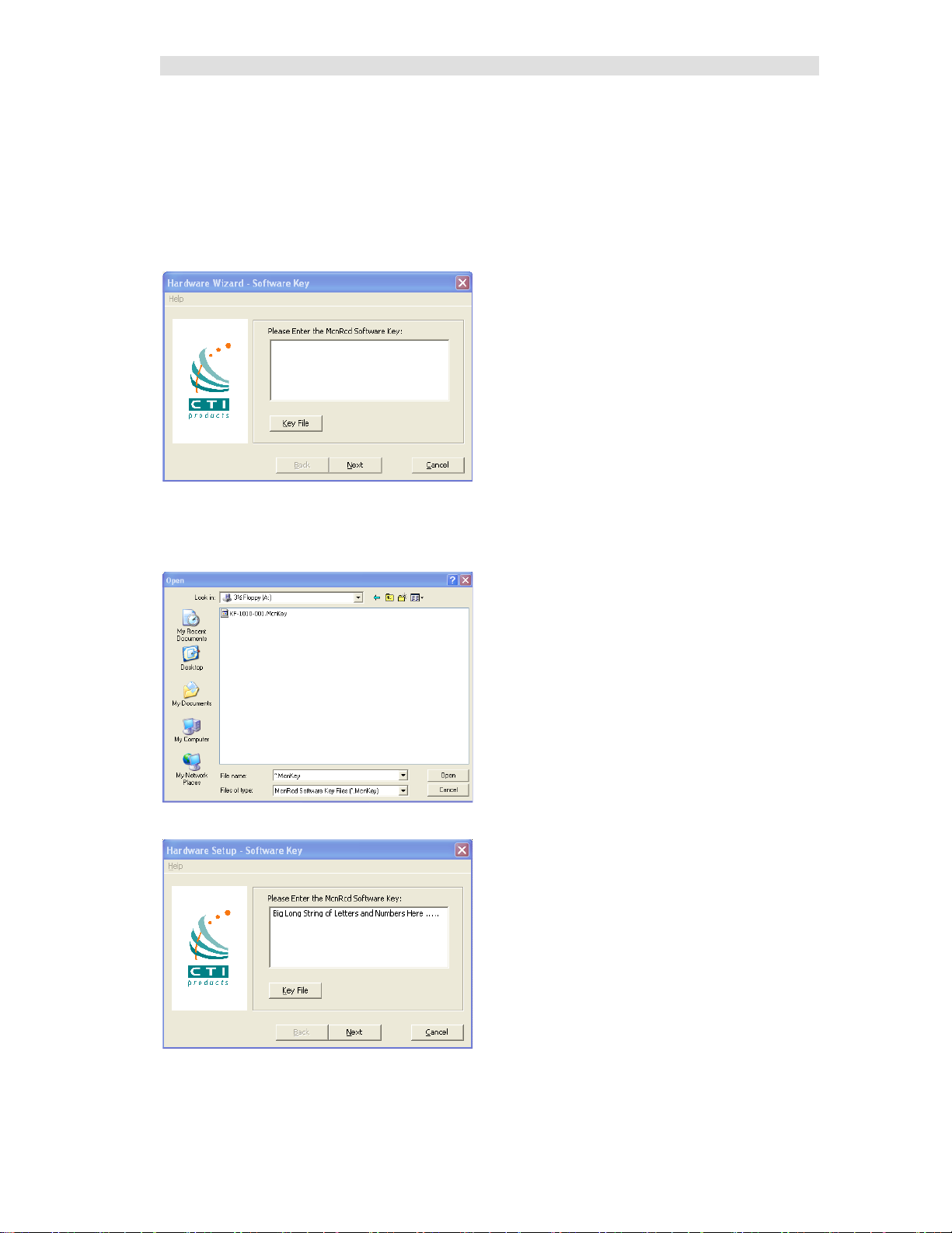
Software Key
You will be asked to enter your software key.
You can type it in if you want to, but it's easier to hit the Key File button and find your key file.
Your software key file will be included on a custom diskette or CD for your system.
Insert the Software Key CD in the CD Drive.
Navigate to find the software key file and click Open.
The Software Key will be entered. Click the Next key.
26 68-12286-110
Page 27
Installation
HW Setup - Network Interface Setup
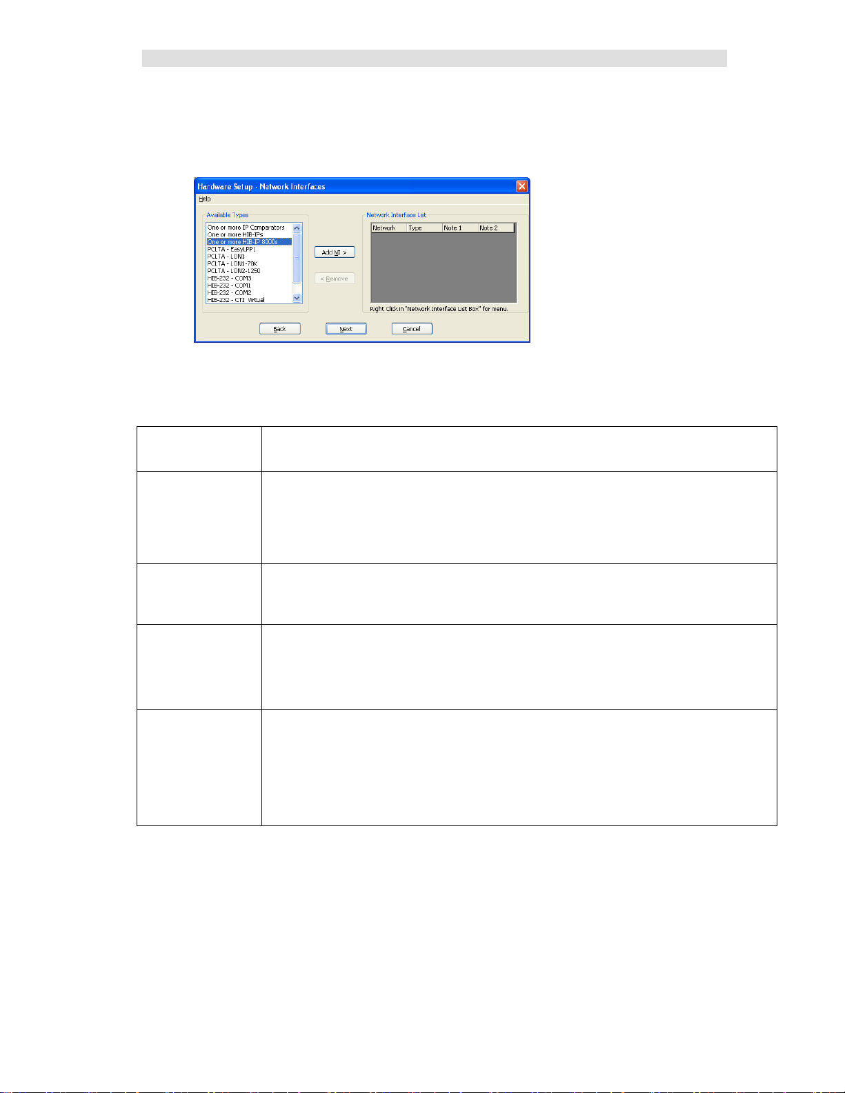
The first time HW Setup is ran, it sees that there is no Network Interface defined on the PC. I t will ask
you what type of Network Interface (NI) you plan to use.
(The number of options i n the "Available Types" list will vary by system.
Most systems will not show the P CLTA, LPP or virtual serial port entries.)
Select the type of Network Interface you intend on using with your system, from the list of possible
types available. Wee the indicated manual sections for f urther instructions:
Network Interface
Type
IP Comparator(s) Choose this if you have one or more of the following Motorola Solutions comparators:
HIB-IP(s)
and
HIB-IP 8000(s)
HIB-232 – COMx Legacy non-dial-up HIB-232 units
PCLTA Legacy internal board in the PC. ( 32-Bit Wind ows only).
Note 1: Yo u will need to set up parameters for the IP Comparators and/or HIB-IP units in the system
configuration files by using McnConfig Ser ver program. You will also have to download settings to the
HIB-IP from the McnConfig Server program.
After you have selected the proper Network Interfaces for your system, go to the Miscellaneous
Installation Considerations section on Page 35.
Description
GCM 8000 or MLC 8000
(either stand-alone or in a Mixed Mode configuration)
See the HW Setup – IP Comparator Network Interface section on page 30 for details
(Also see Note 1 below.)
Legacy Remote Network Interface that connect s to the PC through an IP channel
See the HW Setup – HIB-IP Lega cy Netwo rk Interface section on page 30 for details.
(Also see Note 1 below.)
- HIB-232 units connect to a COM port directly
or through external leased-line modems or equivalent.
See HW Setup – Legacy HIB-232 (non dial-up) section on page 31 for details.
The MCN network will connec t directly to this board.
If there is a PCLTA board that is properly installed, the HW Setup program will list it in
the "Possible Types" list.
See: HW Setup - Legacy PCLTA Setup – 32 Bit Windows only on page 33 for details.
27 68-12286-110
Page 28
Installation
HW Setup – IP Comparator Network Interface
If you will be using one or more IP Comparators, select it from the Possible Types list.
• Select the One or more IP Comparators option.
• Click the Add NI button.
• Click the OK button.
"Comparator" will appear in the Network Interface List.
• If you need to add additional Network Interfaces, do so at this time.
• Click the Next button
• MCN Sever ID:
If you have selected IP Comparators, the following window will appear:
Normally, select MCN Server ID 1.
If you have multiple MCN Server 8 000 PCs, number them se quentiall y.
28 68-12286-110
Page 29

Installation
• A synopsis will be presented:
• Click the Fini s h button.
After you have selected the proper Network Interfaces for your system, go to the Miscellaneous
Installation Considerations se ction on P age 35.
29 68-12286-110
Page 30
Installation
HW Setup – HIB-IP Legacy Network Interface
If you will be using one or more HIB-IP units to connect to a legacy MCN system, select it from the
Possible Types list.
• Select the HIB-IP option.
• Click the Add NI button.
• Click the OK button.
"HIB-IP" will appear in the Network Interface List.
• If you need to add additional Network Interfaces, do so at this time.
• Click the Next button
• Click the Fini s h button.
After you have selected the proper Network Interfaces for your system, go to the Miscellaneous
Installation Considerations se ction on P age 35.
30 68-12286-110
Page 31

Installation
HIB-IP Parameters
As shown in the “Setup HIB-IP” window above, you will later enter the HIB-IP parameters in the
system configuratio n files using the McnConfig program. You will also have to download those
parameters to the HIB-IP using McnConfig.
HW Setup – Legacy HIB-232 (non dial-up)
If you have a HIB-232 module (and are using it directly connected or through leased line modems) select
the proper COM port from the Available Types list box:
The program detects all COM ports reported by Windows.
Depending on your PC, no t a ll ports may be available for use.
* Some COM ports may not be brought out to a connector.
* Some COM ports may be reserved by an internal modem.
(For example, in the snapshot above, COM3 is actually an internal modem.)
USB to Serial Adapters
The MCN Server program will work with some USB to Serial a dapters. We cannot guarantee that it will
work with all such adapters since we cannot test all brands.
Some USB to Serial adapters will change their COM port number when they are plugged into a different
USB connector. If you are using one of these and you chang e its connection, you wil l have to r e-run the
HW Setup progra m to select the new COM port.
• Select the proper COM Port and Click the Add N I button
• Select the ap p r o p r iate baud rate. Be sure that the baud rate matches the Baud rate switches on
the HIB-232 module.
(The Gro up and Module addresses for the HIB-232 unit are set with rotary switches
on the unit. Se e Important: MCN Address Setting on Page 33 for more information on MCN
addressing. )
• Click the OK button.
31 68-12286-110
Page 32

Installation
The HIB-232 unit will appear in the Network Interface List.
• If you ne ed to add additional Network Interfaces, do so at this time.
• Click the Next button
• Click the Fini s h button.
The HW Set up program will save the setting in the registry.
This setting will be used by the MCN Server program.
After you have selected the proper Network Interfaces for your system, go to the Miscellaneous
Installation Considerations se ction on P age 35.
32 68-12286-110
Page 33

Installation
HW Setup - Legacy PCLTA Setup – 32 Bit Windows only
If a PCLT A Card (and its driver) are properly installed on your PC, the HW Setup program will detect it
and present it in the Possible Types list box.
You can check to see if the PCLTA card is installed and operational, by going to Control Panel and
running the Lonworks application. You may then click on the Diagnostics tab and look for a response
box without error indications, if the installation was done correctly.
Note: There are no PCLTA drivers available for 64 Bit Operating Systems.
• Select the PCLTA and click the Add NI button.
The Group/Module address defaults to “F0/10” during installation.
• Change the Gro up and Module address as required for your system.
• Click the OK button.
Some complex systems may use MCN Advanced Server with multiple PCLTAs. These steps will need
to be repeated for each PCLTA.
Important: MCN Address Setting
Each PC and each MCN module in the system must have a unique address. If you are setting up
multiple PCs, be sure to set up each PCLTA card with its own address. Typically, PCLTA cards are
addressed in Group F0 starting at Module 10.
If you have a Custom Engineered System (with custom system documentation part number
KA-8xxxx-xxx), be sure to set the PCLTA address to the Group & Module numbers shown in your
documentation. Failure to do so may cause the system not to work
• In t he above wi ndow, click the OK button.
33 68-12286-110
Page 34

Installation
The PCLTA will appear in the Network Interface List:
• If you ne ed to add additional Network Interfaces, do so at this time.
• Click the Next button.
• Click the Fini s h button in the confirma t ion window.
The appropriate information for the PCLTA is now stored in the registry and will be available for use by
McnConfig and MCN Server programs.
The MCN Group and Module addresses are set up on hex rotary switches on the back of the HIB-232
unit.
After you have selected the proper Network Interfaces for your system, go to the Miscellaneous
Installation Considerations se ction on P age 35.
34 68-12286-110
Page 35

Installation
Miscellaneous Installation Considerations
Changing Settings for your Legacy Network Interface
If you need to change the settings for your Network interface, re-run the HWSetup program. This
program can be used to change the:
• T ype of Network Interface
• PCLTA Device or Group & Module address
• HIB-232 COM Port or Baud Rate
To change these items you can either:
• Double click on the Network Interface to edit its para meters or
• Click the Remove button to remove the Network Interface and select a different one.
If you have a Custom Engineered System (with custom system documentation part number
KA-8xxxx-xxx), be sure to set the PCLTA address to the Group & Module numbers shown in your
documentation. Failure to do so may cause the system not to work
In the above window, click the Next button,
35 68-12286-110
Page 36

Installation
Changing the PCLTA Group/Module A ddress
If the Group/Mod ule address f o r the PCLTA Network Interface needs to be changed (or to query the
PCLTA for i ts current address), simply run the hwsetup.exe program. This progr am can be found in the
main program directory (typically c:\Program Files\CTI Products Inc\McnRcd Server 8000). Then click
the Next button until the following window is displa yed.
The Group/Module address defaults to “F0/00” during installation. However, each PC must have a
unique add ress.
In the above window, click the Next button, then the Finish button to complete the address change for
the PCLTA Network Interface.
PC Power Options Setup
The “Power Options” icon in the Control Panel allows for a wide variety of PC operation parameters.
However, installation of MCN Ser ver software will disable any possibility of the PC going into the
Standby or Hibernate Mode.
The monitor may be allowed to “sleep” as long as the “Monitor Timeout” is less than the “Standby
Time”. Otherwise, the monitor will never sleep.
Printer Installation
For printer logging t o occur, a printer must be installed from the Windows operating system. From the
Start menu button on the windows desktop, select “Printers and Faxes” from the list, then select “Add a
Printer” from the list of “Printer T a sks”.
Uninstalling MCN Server Software
To uninstall MCN Server software, insert the MCN Server distribution CD into the CDROM drive.
Click the Start menu button on the Windows desktop, then select “Run …” from the list. In the “Run”
dialog box, type d:setup.exe (where d is the drive letter of the CDROM drive), then click the OK button.
In the “InstallShield Wizard” window, select “Remove”, then click the Next button. Follow the prompts
until the InstallShield Wizard complete s the removal.
36 68-12286-110
Page 37

Installation
Installing MCN Client Program
You would normally install the MCN Client program on a separate PC from the MCN Server, but you
can also install a copy on the MCN Server PC.
You must have Ad ministrator rights to install the MCN Client program.
The installation steps are shown below.
Read the License Agreement.
If you agree to the terms, click the "I Accept…" button as shown above and then hit the Next button to
continue toe installation.
37 68-12286-110
Page 38

Installation
Enter your user in formation.
Select the “Setup Type” as “Client”.
38 68-12286-110
Page 39

Installation
After you confirm everything is in order, hit Next.
The Installshield program will instal l the files.
39 68-12286-110
Page 40

Installation
Click the Finish button to finish.
40 68-12286-110
Page 41

Interfacing to IP Comparators GCM 8000 Comparators
Interfacing to IP Comparators
You will use the MCN Config Server to enter information about your IP comparators and their receivers
into the MCN system data files. You will need to know different information for the GCM 8000 and
MLC 8000 Analog Comparators as described in the next sections. You will need the data on both the
GCM 8000 and MLC 8000 Analog Comparators if you are using them in a Mixed Mode Voting
Solution.
GCM 8000 Comparator Interfacing
The GCM 8000 comparator can handle up to 64 receivers, connected over IP. The GCM 8000
Comparator has 64 fixed slots or ports for the receivers that connect to it. as shown in the CSS screen
shot below:
When a GCM 8000 comparator is added in MCN Config Server software, the program allocates entries
for 64 receivers for the comparator in the Receiver Window. These receivers map directly to the 64 slots
in the GCM 8000 comparator as shown in the SubSite Num field in the above screen shot
The Aliases in the CSS software are used for the technician's convenience to keep track of the BRs
connected to the GCM 8000. The receiver names must be entered in the MCN Config Server software.
The GCM 8000 CSS does not support the Windows Copy command, so you will have to enter the
Aliases for the Subsites (BRs o r Receivers) i nto the Receiver Window by hand.
Information needed about the GCM 8000
Two types of data are needed to enter the GCM 8000 comparator into the MCN Server 8000 System
Data Files:
• GCM 8000 IP Address Entered into the GCM 8000 Hardware Configuration window
• List of Receivers 1-64 Entered into the Receiver Window – for Receivers 1-64
41 68-12286-110
Page 42

Interfacing to IP Comparators GCM 8000 Comparators
GCM 8000 Subsite Assignment (BR/CM Pairing) Programmed in BR
The Subsites (BRs or receivers) are not assigned in the CSS for the GCM 8000 comparator. The Subsite
numbers are assigned in the CSS for each of the GTR 8000 BRs and the GPW 8000 Satellite Receivers
as shown below:
GCM 8000 Limitations
The GCM 8000 comparator has the following limitations
Maximum of 3 Simultaneous MCN Servers or CSS Sessions
The GCM 8000 supports only 3 simultaneous connections for real-time sessions. T hese sessions
include:
• CTI MCN Server 8000 Software
• CSS Software
From a practical standpoint, th is means that you should limit the number of MCN Servers talking to a
GCM 8000 comparator to two. This will allow an open session for the CSS software.
MCN Server & CSS cannot run simultaneously on the same PC
The GCM 8000 comparator cannot talk to both the MCN Server software and the CSS software running
on the same PC simultaneously.
• If you have to run CSS on t he Server PC, you will have to exit t he MCN Server software .
• If you have the CSS software running on the Se rver PC and try to start t he MCN Ser ver
software, it will not communicate to the GCM 8000 comparator.
42 68-12286-110
Page 43

Interfacing to IP Comparators GCM 8000 Comparators
Displayed State
Meaning
Error
Undefined Status
Offline
Server cannot talk to the GCM 8000 comparator (Note1)
(Blank)
No Activity
DISABLE
Permanently Disabled by CSS (note the capital letters)
Disable
Disabled via MCN Server 8000 or MCN Client
Fail
Subsite Failed - Comparator cannot talk to BR
Rx
Voice Receive acti vity
Rx Data
Data Receive activity
Forced Vote
Force Vote (but not yet Voted)
Vote
Voted
Vote Data
Voted for Data
Last Vote
Last subsite voted (GCM LV Display Tables only)
GCM 8000 Can't Disable a Failed Subsite
The legacy Astrotac 3000 and GCM 8000 comparators will not allow the user to Disable a re c e iver
(subsite) if it is in Fail mode. T his applies to both the MCN Server 8000 application and the Real-Time
portion of the Motorola CSS software.
GCM 8000 Disables are Reset on Fail Condition
The GCM 8000 comparator will reset the Disable condition if a receiver (subsite) goes into Fail mode.
This applies to both the MCN Server 8000 application and the Real-Time portion of the Motorola CSS
software.
GCM 8000 CSS Software latches Votes
If s receiver (subsite) is Force-Voted from the CSS Local Status Screen, it will latch in the Force Vote
state. No other receivers will be voted in the GCM 8000. The latched Force Vote can be unlatched from
the MCN Server 8000 by pressing and releasing the left mouse button.
GCM 8000 Status Display
The possible states for the GCM 8000 subsites (receivers) include:
The above states are defined in the GCM 8000 and the GCM LV Display Tables.
Note 1: The Offline state could be caused by the following:
a. GCM 8000 IP address in the MCN System Configuration Files is wrong
b. MCN Server cannot talk to the GCM 8000 comparator (possible network problem)
c. If the MCN server has multiple NIC cards, the wrong one may be selected.
Note 2: The Last Vote indication will only be displayed when that subsite is other wise i n the Idle state.
Permanently Disabled (Unconfigured) Subsites
Permanently Disabled sites (Unconfigured) will show up as DISABLE or DIS (in capitals) to distinguish
them from the subsites that are disabled from MCN Server 8000 or the CSS Local Status Screen.
43 68-12286-110
Page 44

Interfacing to IP Comparators MLC 8000 Comparator
BRs – Receivers
BRs – Receivers
Voter (VGU) Chan 1
Voter (VGU) Chan 2
MLC 8000 Analog Comparator Interfacing
The MLC 8000 Analog Comparator can also handle up to 64 receivers, connected over IP, but the
linking between the MLC 8000 Analog Comparator and the MCN Server 8000 system is handled
differently from the GCM 8000.
The MLC 8000 Analog Comparator is made up of two types of units:
• VGU MLC 8000 Analog Comparator (which connects to the console)
• AGU MLC 8000 Subsite Link Converter (which connects to the BRs)
We need to know information from both types of units
Information needed about the MLC 8000 Analog Comparator
The information we need to know about the MLC 8000 Analog Comparator to ether into the MCN
Server 8000 System Data Files is:
• VGU IP Address Entered into the GCM 8000 Hardware Configuration window
• Voter ID Entered into the GCM 8000 Hardware Configuration window
• AGU BR Port ID For each of the BRs in the syst em
Entered in the MLC ID field for the receiver in the Receiver window
• AGU BR Name Receiver name for each BR in the system
Entered in the Name field for the receiver in the Receiver window
MLC 8000 Channel Cluster Tree
Figure 3 shows the Channel Cluster Tree in the MLC 8000 CT (Configuration Tool) software.
(AGU Ports) Ch an 1
(AGU Ports) Ch an 2
Figure 3 MMC Channel Cluster Tree in the MLC 8000 CT Software
This Channel Cluster shown in Figure 3 includes two comparators:
• Channel 1: 4 BRs (Receivers)
• Channel 2: 8 BRs ( Receivers)
44 68-12286-110
Page 45

Interfacing to IP Comparators MLC 8000 Comparator
MMC_Config.csv File -- MLC 8000 Analog Comparator Data
When a Channel Cluster i s saved from the MLC 8000 CT (Configuration Tool) software, the software
generates a file with data that is needed for MCN Config Server software. One file is generated for each
cluster (up to 4 channels). The file is typically stored at:
C:\Motorola\MLC8000 CT\ClusterName\MMC_Config.csv
(Where ClusterName is the name o f the Cluster to use)
The MMC_Config file can be opened in Wordpad or Excel.
Figure 4 MMC_Config File – Formatted in Excel
Figure 4 shows an MMC_Config file opened in Excel with some formatting added. The format of the
file may change fr o m version to version of the MLC 8000 CT software.
Sorting the MMC_Config File
The MMC_Config file does not always have the items ordered as one would expect. Channels 1 & 2 in
Figure 4 are intermixed. If this is a problem (especially with larger systems), it is recommended that you
sort the portion of the file relating to the AGUs and VGUs.
1. Open the file in Excel.
2. Saved as XLS file.
3. Add formatting as required.
4. Sort the Devices portion of the file (with the AGU & VGU information.). Sort By:
Channel Name
Device IP
BR Port
5. Re-save the file.
Note:
We recommend NOT re-saving the file to the CSV format
(unless you make a copy with a different name).
It is easy to corrupt a file and make it unusable for the CT program.
45 68-12286-110
Page 46

Interfacing to IP Comparators MLC 8000 Comparator
Figure 5sho ws the Sort process.
Figure 5 Sorting the MM C_Conf ig File
The sorted result is shown in Figure 6,
After the sort:
• The Channels will be together.
• However, the BRs (AGU Ports) will not necessarily in BR List Order
Figure 6 Sorted MMC_Config file with additional formatting
46 68-12286-110
Page 47

Interfacing to IP Comparators MLC 8000 Comparator
Figure 6 shows two radio channels, each with its own voters and BRs. For each of the channels:
• The top horizontal rectangles show the:
Voter ID (Device Id field)
VGU IP Address (Device IP field)
Channel Name (Channel Name field)
• The vertical rectangles shows the:
AGU Port IDs (Device ID Field)
Receiver Names (BR Subsite field)
Note that the Channel IDs (2809 & 8201) correspond to the VGU IDs.
Copying and Pasting from the MMC_Config file
There is no automatic import of the data from the MMC_Config.csv file into the MCN Server 8000
system configuration files. You can, however, open the MMC_Config.csv file in Excel and copy &
paste the information into the fields in the Receiver Window in MCN Config Server:
MMC_Config Field Receiver Window Field
Device ID (for BRs / Receivers) MLC ID
BR Subsite Name
BR Name Description (for general reference)
Here are a few things to consider when copying the data into the system configura tion files in MCN
Config::
• Be sure that the Subsites are in the right order.
If they are not, you can copy the Subsite value s and names one at a time.
• If you have a Mixed Mode system, make sure that the Subsites are in the order that matches the
BR Subsite order in the GCM 8000 comparator. If they are not, you can copy the Subsite
values and names one at a time.
• The Subsite Names in the MMC_Config.csv file might not be in the format that you want
displayed. You may have to edit these values for the user in MCNConfig Server.
• You can include the AGU IP Address and Port number in the Description field in the Receiver
Window. T his can be helpful for error logging and troubleshooting.
MLC 8000 Analog Comparator Data for multiple radio channels
The MLC 8000 Analog Comparator CT software can store data for up to 4 channels in a Channel
Cluster.
If your s ys te m has more than 4 radio channels using MLC 8000 Analog Comparators, you will need to
save the system data in groups of 4 radio channe ls. You will need to open separate MMC_cfg.csv files
for each channel cluster.
47 68-12286-110
Page 48

Interfacing to IP Comparators MLC 8000 Comparator
Note: The Device ID in the General Properties.
The Voter ID is sho wn in the
MLC 8000 Analog Comparator CT Software Examples
The following section s show where the MLC 8000 Analog Comparator information is configured. The
screen captures are based on CT Version 2.24. Screens for newer versions may be different.
MLC 8000 Analog Comparator (VGU) Configuration
Right-Click on an MLC 8000 Analog Comparator (VGU) from the main device tree and select
Configure Device.
The General Properties tab has the The Voter Properties tab has the
VGU IP Address VGU Voter ID and Channel Number
tab is NOT the Voter ID.
48 68-12286-110
Voting Properties tab above (2809)
Page 49

Interfacing to IP Comparators MLC 8000 Comparator
The IP configuration tab
has more detailed IP parameters.
49 68-12286-110
Page 50

Interfacing to IP Comparators MLC 8000 Comparator
The Status Tone Timeout will determine
Seconds.
Subsite
MLC 8000 Subsite Link Converter (AGU) Configuration
Right-Click on an MLC 8000 Subsite Link Converter (AGU) Port (BR) from the main device tree and
select Configure Device.
The BR/Console Properties tab has the The Advanced Properties window has t he
BR Name, and AGU Port ID (MLC ID) Status Tone Timeout
The Port box selects which
port to display from the
AGU.
the length of time from loss of Status
Tone to a Fail indication. Default is 60
50 68-12286-110
Page 51

Interfacing to IP Comparators MLC 8000 Comparator
Not the Port ID
The General Properties tab has the The IP Configuration tab has the
Device Name and IP Address Detailed IP information
The MCN System does no t need to know the AGU IP Address, but it can be helpful in troubleshooting.
BR List
Highlight the Voter and select Edit BR List button.
The window shows the lineup of BRs for the cha nnel.
51 68-12286-110
Page 52

Interfacing to IP Comparators MLC 8000 Comparator
MLC 8000 Analog Comparator Limitations
The MLC 8000 Analog Comparator has the following limitations
Maximum of 15 Simultaneous MCN Servers or CSS Sessions
The MLC 8000 Analog Comparator supports 15 simultaneous connections for real-time sessions. These
sessions include:
• CTI MCN Server 8000 Software
• MLC 8000 CT / DA Software
From a practical standpoint, th is should not pose a problem since systems will normally not have more
than 1 or 2 MCN Server PCs.
MCN Server & CT / DA software cannot run simultaneously on the same PC
The MLC 8000 Analog Comparator cannot talk to both the MCN Server software and the MLC 8000 CT
/ DA software running on the same PC simultaneously.
• If you have to run CT software on the Server PC, you will have to exit the MCN Server
software.
• If you have the CT software running on the Server PC and try to start the MCN Server software,
it will not communicate to the MLC 8000 Analog Comparator. You will have to close the CT
software fi r st .
52 68-12286-110
Page 53

Interfacing to IP Comparators MLC 8000 Comparator
Displayed State
Meaning
Error
Undefined Status
Offline
Server cannot communicate with MLC 8000 Comparator (Note 1)
Config Err
(Note 2)
(Blank)
No Activity
Disable
Disabled via MCN Server 8000 or MCN Client
Fail
Subsite Failed - Comparator cannot communicate to BR (Note 3)
Rx
Voice Receive acti vity
Forced Vote
Force Vote (but not yet Voted)
Vote
Voted
Last Vote
Last subsite voted (LV Display Tables only)
MLC 8000 Analog Comparator Status Display Tables
MLC 8000 and MLC LV Display Tables
The possible states for the MLC 8000 Analog Comparator subsites (receivers) include:
The above states are defined in the MLC 8000 and the MLC LV Display Tables.
Note 1: The Offline state could be caused by the following:
a. GCM 8000 IP address in the MCN System Configuration Files is wrong
b. GCM 8000 Voter ID in the MCN System Configura tion Files is wrong
(See the Network Interface window.)
c. MCN Server cannot talk to the MLC 8000 Comparator (possible network problem).
d. If the MCN Server has multiple NIC cards, the wrong one may be selected.
Note 2: The Config Err state could be caused by the following:
a. The MLC ID in the MCN System Configurat ion Files (Re ceiver window) is wro ng.
b. The MLC 8000 Analog Comparator BR is configured in the MCN System Configuration
Files (Receiver window) but it is not co nfigured in the MLC 8000 Comparator BR List.
c. The MLC 8000 Analog Comparator is online, has not sent a status update for this BR.
Note 3: The Fail state could be caused by the following:
a. The BR analog port is disconnected from the MLC 8000 Subsite Link Converter (AGU).
b. The BR has lost po wer.
c. There is no status tone from the BR
d. The Radio Port for this MLC 8000 Subsite Link Converter (AGU) is not calibrated
properly (See the CT software for calibration)
e. The MLC 8000 Analog Comparator (VGU) cannot communicate with the appropriate
MLC 8000 Subsite Link Converter (AGU). In this case, all the BRs associated with this
MLC 8000 Subsite Link Converter (AGU) will be in the Fail state.
Note 4: The Last Vote indication will only be displayed when that subsite is other wise i n the Idle state.
WARNING: DO NOT ATTEMPT TO CHANGE THE BIT VALUES OR ENTRY O RDER IN
THE DISPLAY TABLE.
53 68-12286-110
Page 54

Interfacing to IP Comparators MLC 8000 Comparator
Displayed State
Meaning
Error
Undefined Status
Offline
Server cannot communicate with MLC 8000 Analog Comparator
(Note 1)
Config Err
(Note 2)
(Blank)
No Activity
Disable
Disabled via MCN Server 8000 or MCN Client
Fail
Subsite Failed - Comparator cannot communicate to BR (Note 3)
Rx
Receive Signal Quality 0
| Rx
Receive Signal Quality 1
|| Rx
Receive Signal Quality 2
||| Rx
Receive Signal Quality 3
|||| Rx
Receive Signal Quality 4
||||| Rx
Receive Signal Quality 5
TX
Transmit Active
Tx/Rx
Tx & Rx Signal Quality 0
| Tx/Rx
Tx & Rx Signal Quality 1
|| Tx/Rx
Tx & Rx Signal Quality 2
||| Tx/Rx
Tx & Rx Signal Quality 3
|||| Tx/Rx
Tx & Rx Signal Quality 4
||||| Tx/Rx
Tx & Rx Signal Quality 5
Vote
Vote Signal Quality 0
| Vote
Vote Signal Quality 1
|| Vote
Vote Signal Quality 2
||| Vote
Vote Signal Quality 3
|||| Vote
Vote Signal Quality 4
||||| Vote
Vote Signal Quality 5
Last Vote
Last subsite voted (LV Display Tables only)
MLC Tech Display Table
The MLC Tech Display Table is provided to help technicians troubleshoot MLC 8000 Analog
Comparator systems. Separate screens or tabs can be set up using this Display Table for Technician use.
The MLC Tech Display Table adds the more technical indication to the display including Signal Quality
and TX indication. The possib le state s for the MLC 8000 Analog Comparator subsites (receivers) using
this Display Table are:
The above states are defined in the MLC Tech Displa y Ta ble only.
Notes 1-4: Same as for previous table.
Note 5: This table is best used with a fixed width font (such as Courier New) so that the signal bars
align.
Note 6: Do not use this Display Table for normal users. It will be too cluttered.
WARNING: DO NOT ATTEMPT TO CHANGE THE BIT VALUES OR ENTRY O RDER IN
THE DISPLAY TABLE.
54 68-12286-110
Page 55

Interfacing to IP Comparators Mixed Mode Comparator
MM - Mixed Mode Voting Solution Interfacing
The Mixed Mode Voting Solution is a combination of a GCM 8000 Comparator and an MLC 8000
Analog Comparator. When interfacing to a Mixed Mode system, you will need the information from
both of those comparators:
GCM 8000 Information:
• GCM 8000 IP Address Entered into the Mixed Mode Confi gur at ion window
• List of Receivers 1-32 Entered into the Receiver Window – for Receivers (Subsites) 1-32
MLC 8000 Analog Comparator Information:
• VGU IP Address Entered into the Mixed Mode Co n fi gura tion window
• Voter ID Entered into the Mixed Mode Confi gur ati o n wind ow
• AGU BR Port ID For each of the BRs in the syst em
Entered in the MLC ID field for the receiver in the Receiver window
• AGU BR Name Receiver name for each BR in the system
Entered in the Name field for the receiver in the Receiver window
Receiver (Subsite) Order for Mixed Mode Systems -- Very Important!
Since a Mixed Mode system uses both a Digital (GCM 8000) and a MLC 8000 Analog Comparator, it is
very important to make sure that the receiver (subsite) information is entered into the MCN Config
Server program in the proper order. The following principles hold in determining the receiver order:
1. Each radio channel may have different receiver (Subsite) orders.
2. If there are multiple radio channels with the sa me complement of Subsite locatio ns, it is
recommended that the Subsites in all channels be configured in the same order.
3. The Subsite numbers configured in the GTR 8000 BRs and GPW 8000 Satellite Receivers for a
particular radio channel control the Subsite order in that channel's GCM 8000 comparator.
4. Since the Subsite name can be hand-entered in the GCM 8000 comparator CSS, it is possible to
enter the wrong Subsite name. Make sure that the list of Subsite names in the GCM 8000 CSS
matches the actual order of the GTR 8000 and GPW 8000 units.
5. The Subsite order (1-64) in the GCM 8000 comparator controls the receiver order (1-64) in the
Receiver Window in the MCN Config Server software.
6. Enter the proper Receiver Names (as determined by the GCM 8000 Subsite order) in the MCN
Config Server Software Receiver Window.
7. The Subsites listed in the MLC 8000 Analog Comparator CT software (and the resulting
MMC_Config.csv file) are listed in the order that they were enter e d when the system was
configured in the CT software. This order might not be the same as the order in the GCM
8000 comparator.
It is recommended that the order is kept the same, but it is not imperative that it is.
8. After the receiver Subsite information from the GCM 8000 is entered into the MCN Config
Server software, enter the proper AGU Port ID in the MLC ID field for that subsite.
55 68-12286-110
Page 56

Interfacing to IP Comparators Mixed Mode Comparator
Mixed Mode System Limitations
Mixed Mode systems will have the same limitations as their constituent GCM 8000 and MLC 8000
Analog Comparators as described in the CGM 8000 and MLC 8000 Analog Comparator Limitations
sections:
• Maximum of 3 MCN Servers connected to the GCM 8000 comparators. If the MCN Servers
are in an Astro™ 25 RNI, the RNI infrastructure supports only 2 MCN Server 8000 PCs.
• Neither the GCM 8000 CSS software nor the MLC 8000 Analog Comparator CT / DA software
can run simultaneously on the same PC as the MCN Server.
• The GCM 8000 comparator cannot disable subsites that have failed
• The GCM 8000 comparator will reset the Disable status if a subsite goes into Fail.
56 68-12286-110
Page 57

Interfacing to IP Comparators Mixed Mode Comparator
Displayed State
Meaning
Error - Undefined
Undefined Status
(Blank)
No Activity
Cfg Err A
Configuration Error MLC
Offline D
Offline GCM
Offline D / Cfg Err A
Offline GCM & Config Error MLC
Offline A
Offline MLC
Fail A
Fail MLC
Fail D
Fail GCM
Fail D / Cfg Err A
Fail GCM & Config MLC
Fail D + A
Fail Both
Dis A
Disable MLC
Dis D
Disable GCM
Dis D + A
Disable both
DIS D + A
Permanently Disable GCM & Disable MLC
Dis A / Fail D
Disable MLC & Fail GCM
Dis D / Fail A
Disable GCM & Fail MLC
DIS D / Fail A
Permanent Disable GCM & Fail MLC
Dis D / Cfg Err A
Disable GCM & Config Err MLC
DIS D / Cfg Err A
Permanent Disable GCM & Config Err MLC
Offline D / Fail A
Offline GCM & Fail MLC
Offline D / Dis A
Offline GCM & Fail MLC
Offline A / Fail D
Offline MLC & Fail GCM
Offline A / Dis D
Offline MLC & Disable GCM
Offline A / DIS D
Offline MLC & Permanently Disable GCM
Offline A + D
Offline both
Rx
Voice Receive acti vity
Rx Data
Data Receive activity
Forced Vote
Force Vote (but not yet Voted)
Vote
Voted
Vote Data
Voted for Data
Last Vote
Last subsite voted (LV Display Tables only)
Mixed Mode Status Display
The possible states for Mixed Mode comparator systems using the Mixed Mode and the MM LV
Display Tables are:
The above states are defined in the Mixed Mode and the MM LV Display Tables.
Note 1 The notes from the other IP Comparator Display Tables apply as appropriate.
Note 2: "A" = Analog (MLC 8000 Analog Comparator); "D" = Digital (GCM 8000)
Note 3: I n normal operation, only a few of these states will be displayed.
Note 4: Acti ve Call states (Vote, Rx) will take priority over background states (Idle , Dis, Fail, Offline)
Note 5: Acti ve Call states for Digital (GCM 80 00) will have priority over Analog calls.
Note 6: The implementation of this Display Table is extremely complicated. The above states are not in
the same order as they appear in the real Display Table.
WARNING: DO NOT ATTEMPT TO CHANGE THE BIT VALUES OR ENTRY O RDER IN
THE DISPLAY TABLE.
57 68-12286-110
Page 58

Interfacing to IP Comparators Mixed Mode Comparator
Mixed Mode Tech Status Displays
The MM Tech Display Tables are provided to help technicians troubleshoot Mixed Mode systems.
Separate screens or tabs can be set up using these Display Tables for Technician use.
MM Tech Display Table
The MM Tech Display Table is similar to the MM LV Display table, except it adds more detail in the
cases of both Digital and Analog Activity at the same time. It has the following modifications:
• Added "D" or "A" suffix for Rx & Vote states
• When there is both Digital & Analog activity, both are shown.
• Analog Rx is changed to a brownish color.
• Analog Vote is changed t o a violet color
You can look at this Display Table in the Display Table window in MCN Config Server software.
MM-GCM Tech Display Table
This Display Table is for Mixed M ode systems, but it looks at only the GCM 8 000 (Digital) signals, plus
the Last Vote. It is somewhat similar to the GCM LV Display Table It can be used for troubleshooting
a Mixed Mode system if you want to look just at the GCM 8000 data.
You can look at this Display Table in the Display Table window in MCN Config Server software.
Note 1: The Last Vote indication will be set on either digital or analog activity.
MM-MLC Tech Display Table
This Display Table is for Mixed M ode systems, but it looks at only the signals from the MLC 8000
Analog Comparator, plus the Last Vote. It is somewhat similar to the MLC LV Display Table It can be
used for troubleshooting a Mixed Mode system if you want to look just at the data from the MLC 8000
Analog Comparator.
You can look at this Display Table in the Display Table window in MCN Config Server software.
Note 1: The Last Vote indication will be set on either digital or analog activity.
Note 2: I f there is b oth analog and digital activity, you will not see a Vote indication using thi s table
since the MLC 8000 Analog Comparator Vote bit is suppressed in the program whenever there is a Vote
in the GCM 8000.
58 68-12286-110
Page 59

System Considerations
Interfacing to Legacy Equipment
The MCN Server 8000 communicates to Legacy Equipment (Non-IP comparators and I/O devices) via
modules attached to the MCN Monitoring and Control Netwo r k:
Device MCN Module Type
Astrotac 3000 Comparators AIB Modules
Digitac Comparators CIB Modules
Spectra-TAC Comparators CIB Modules
Competitive Comparators CIB Modules
I/O & Alarm Points GPIO Modules
The MCN modules shown above all communicate on a 78 Kbit wired network.
Larger systems may include a 1.25 Mbps high-speed backbone network that connects to the MCN
modules through MCN Routers and EXB Network Extender Modules.
The MCN Server 8000 connects to IP comparators directly through an IP network, but it connects to the
MCN networ ks through a discrete Network Interface. The following types are available:
Network Interface Type MCN Network Speed
HIB-IP IP Module 78 Kbps
HIB-232 RS-232 Serial 78 Kbps
PCLTA-21-78K PCI Board 78 Kbps
PCLTA-21-1250K PCI Board 1.25 Mbps
The standard MCN Server 8000 software can support a single Network Interface (usually a HIB-IP unit).
Additional Network Interfaces can be supported by purchasing expansion options.
When interfa cing to legacy equipment using MC N modules, you will nee d to know:
• Network Interface Information (entered in Network Interface window):
Network Interface Type
Network Interface Parameters
MCN Group & Module addresses
IP parameters (for HIB-IP units)
• MCN Module Information (entered in Hardware window)
Module Type
MCN Group & Module addresses
• Receiver & I/O Point Information (entered in Receiver window)
Receiver and/or I/O Point Name
Type of Display Table to use (Comparator, Alarm, Door, etc.)
The Configuring a System - McnConfig Server 8000 Program section of this manual has references to
the above items throughout.
More information on the MCN module s , and the MCN network can be found in the appr opriate manuals.
See the Reference Documents section of this ma nual for a list of manuals.
59 68-12286-110
Page 60

System Considerations
System Considerations
IP Networking Considerations
• For ASTRO® 25 systems, all equipment (IP Comparators, HIB-IP units, MCN Server, and
Clients) must be located at the pr oper sites and connected to the prop e r IP switches according to
the Motorola IP Plan (per specific ASTRO® 25 release).
• For ASTRO® 25 systems, the appropriate CTI Products, Inc. equipment must be enabled in the
MSI TNCT tool (done at the factory) to enable appropriate IP routing for the CTI Products
hardware and software.
• For operation on other systems, the installer should consult with the customer's network
engineers for proper settings.
• IP network infrastructure equipment (switches, routers, etc.) must be configured properly to
allow communication between the IP comparators, the MCN Server 8000, HIB-IP units, and the
MCN Clients.
• The IP network routers and switches must be configured to pass IP Multicast traffic from the
MCN Server to the Clients.
• The system requires static IP addresses for the following items:
MCN Server 8000 PC
ClientRCD PCs
HIB-IP units
GCM 8000 & MLC 8000 IP Comparators
Multicast IP Address for Server to Client traffic.
All IP addresses, IP Subnets, and Subnet Masks should be set based on the proper settings for
the particular system.
Software Co-habitation and PC Locations
• For ASTRO® 25 7.13 systems, MCN Server 8000 software may be installed on:
Stand-Alone PC
Co-Habbed on an NM Client PC.
• For ASTRO® 25 7.13 systems, ClientRCD software may be installed on:
Stand-Alone PC
Co-Habbed on an NM Client PC.
Co-Habbed on an MCC 7500 Console PC
• For ASTRO® 25 7.13 systems, the va rious components of an MCN system (MCN Server
8000, Client RCD, HIB-IP units, and IP comparators cannot bridge the RNI-CEN demarcation
point. There are two possible configurations:
a. All compone nts must be within the RNI or
b. All components must be outside the RNI in the CEN.
60 68-12286-110
Page 61

System Considerations
Co-located Vortex
Site in Zone Core
Co-located NM Site in
Zone Core
IP Simulcast
Prime Site
Conventional
Hub
MCN
8000
Yes
Yes
No
Yes
CTI
Client
Yes
Yes
No
Yes
HIB-IP
No
No
Yes
Yes
• For ASTRO® 25 7.13 systems, the PCs running MCN Server 8000 and ClientRCD software
may be installed only at the following locations:
Zone Core (Not on NM Subnet – no Multicast support)
K-Core
Collocated Vortex / NM Disp atch Site in Zore Core
Note: A Vortex /NM Dispatch Site may not be able to communicate with all the
comparators at other sites. Only Zone Core or K-Core or collocated Vortex / NM
Dispatch Site in Zore Core is available to see all the comparators.
• For systems not running in an official MSI RNI, some of the above limitatio ns may not apply,
but the non ASTRO® -specific considerations will app ly.
Valid locations on the A7.13 RNI are shown below
Server
HIB-IP Considerations
• Legacy HIB-IP modules (versions below 400) are not intended for operation across an Astro®
25 7x Radio Network Infrastructure (RNI).
• HIB-IP 8000 modules (HIB-IP modules version 400 and up) support special UDP Ports
required to run across an Astro® 25 7.13 RNI.
• For ASTRO® 25 7.13 systems, HIB-IP modules may be installed only in the following
locations:
Simulcast IP Prime Sites
Conventio nal Hub (C-Sub Hub) Sites
Default Software Settings
• The defaults in the MCN Server 8000 and the MCN Client are configured to run in an
ASTRO® 25 7.12 system and higher.
• The default UDP ports for the Server and Client are set according to Motorola's IP plan (per
specific ASTRO® 25 release).
• The default Multicast IP address for the MCN Server 8000 software is configured for:
MCN Server #1 in Zone 1 at the Main Prime site.
If your system configuration is different, please refer to the Motorola IP Plan (per specific
ASTRO® 25 release) for the proper Multicast IP address.
Windows Accounts
In general, the programs should be run with the l east privileges consistent with proper program
operation.. The programs need t he following rights::
61 68-12286-110
Page 62

System Considerations
• Setup.exe (Installation) Administrator
• HWSetup Administrator
• MCN Config Server 8000 Administrator
• MCN Server 8000 User (Note 1)
• ClientRCD User (Note 2)
Note 1 Depending on the rights on various files and folders, Administrator right s may be needed
when configuring IP se ttings and c hanging othe r system settings.
Note 2 Depending on the rights on various files and folders, Administrator rights may be needed
when configuring the I P settings for the Client, and the list of IP addresses for the Server(s).
Permissions File Locations & Permissions
The default installation locations for the MCN Server 8000 Ser ver a nd Client systems (for Windows 7)
are:
MCN Server 8000
Program Files C:\Program Files (x86)\CTI Products Inc\McnServer 8000
Example Files C:\Program Files (x86)\CTI Products Inc\McnServer 8000\Example System
Config Log: C:\ProgramData\CTI Products Inc\McnConfig
McnConfig.log
System Log: C:\ProgramData\CTI Products Inc\McnRcd
McnSystem.log Users must have Read & Write access rights
Run-Time Log: C:\ProgramData\CTI Products Inc\McnRcd
MCNRCD.log Users must have Read & Write access rights
Saving System Configuration Files from MCN Config Server:
• Save to a folder in which User accounts have Read rights.
• Do not save to the Program folder.
MCN Client
Program Files C:\Program Files (x86)\CTI Products Inc\McnServer 8000
Server List C:\ProgramData\CTI Products Inc\McnClient
ServerList.RcdCli Users must have Read & Write access rights
Cache Files: C:\ProgramData\CTI Products Inc\McnClient\cache
*.RcdChe FILES Users must have Read & Write access rights
62 68-12286-110
Page 63

Configuring a System McnConfig Server 8000 Program
Configuring a System - McnConfig Server 8000 Program
The MCN Config Server 8000 program is used to configure an MCN system. System configuration
involves:
1. Defining system reso urces in the Resource Windows, such as Network Interfaces, Hardware
Modules, Receiver Names and, Channels;
Designing t he Display Windows to be displayed for the MCN Server and MCN Cli ent programs;
Building a list of Display Windows (screens) available to the various Client PCs.
Resource Windows
The MCNConfig program will be used to define your system by entering data into the following
Resource Windows. (There is only one of each type of Resource Window for each system.)
Network Interface Indicates which Network Interface is used for this system.
If you are using a HIB-IP unit, this is where you will enter the IP and M CN
address settings. IP Comparators also have an entries in this window.
Hardware Enter the information about the hardware modules
(IP Comparators, CIBs, AIBs, IOBs, etc.) present in the s ystem.
Receivers Enter the site Names and Descriptions for all the receiver s in the system.
Channels Enter the names of the radio channe ls used in the system. Each channel can
have multiple hardware modules.
Display Tables Each type of device to be monitored and controlled will have a Display
Table. The Display Table maps the hardware I/O bits of the device into
status indications.
The MCN Server software ships with standard Comparator Display Tables
and a number of generic I/O Display Tables.
Customized Display Tables can be created with special status text displays
(On/Off, Alarm,, Run/Nor mal, e tc . ) for control and monitoring devices in
your system.
63 68-12286-110
Page 64

Configuring a System McnConfig Server 8000 Program
1 2 3
4
Resource Table Links
Certain fields of the resource windows link to each other as shown by the arrows.
1. The Network Inte rface links to the devices connected to it that are sho wn in the
Hardware window. In this example, the HIB-IP Network Interface has (6) MCN
legacy modules connected to it: (4) CIB modules, (1) AIB module, and (1) IOB
module.
(The GCM 8000 Network Interface has just its GCM 8000 comparator linked under it.
2. Each Module in the Hardware Window can point to a Channel in the Channel window.
3. Each Module in the Hardware Window points to all the Receivers (subsites) or I/O
points associated with it. In the example the CIB module points to its (8) receivers.
An IP Comparator Module points to (64) receivers.
4. Each Receiver or I/O Point in the Receivers window points to a Display Table tab.
This determines how the status information from the comparator or I/O module will be
displayed.
64 68-12286-110
Page 65

Configuring a System McnConfig Server 8000 Program
Display Windows (Status Screens)
Display Windows are the screens that will be used to display the system status in the MCN Server and
Client programs. You must build at least one Display Wi nd ow in order for the MCN Server and Client
programs to display your system.
• Each screen can have multiple rows and columns for the Receiver and I/O points.
• Each status screen can contain multiple Tabs and multiple channels.
• Multiple Screens can be defined within the Disp lay window for the system.
If there are multiple screens built wit hin the Display window, you will have to c lick the “View” tab and
select “Display Window” and choose which specific screen you want to view.
The following is an example of the D isplay Windows configurability:
For Technici ans, a large display gri d with one ta b showing all systems on a single gr id.
For Dispatchers, a small grid with multiple tabs showing only one channel p e r tab.
Different Display Windows for d ifferent dispatchers with different subsets of channels available.
(Police channels for Police dispatcher, Fire & EMS channels for Fire Dispatcher, etc.)
Typical Technician Display Window
Typical Dispatcher Display Window
65 68-12286-110
Page 66

Configuring a System McnConfig Server 8000 Program
Example System
You can load an Example System from the “Example System” directory off the main program directory
(typically c:\Program Files\CTI Products Inc\MCN Server 8000\Example System).
Default Display Window
If you forget to build a Display Window for your system, the MCN Config Server software will generate
a warning.
Missing Display Window Warning
The program will also generate a default Display Window. This will not have any receivers placed on it,
but will give you instructions to r e mind you what needs to be done as shown below.
Default Display Screen
66 68-12286-110
Page 67

MCNConfig Program: Navigating
Navigating through MCNConfig Server
The MCNConfig program is a 32-Bit Windows program. Navigation, menus and toolba rs are similar to
other Windows programs.
Standard Windows Hot-Keys that can be used with this program include:
Ctrl-C Copy current selectio n to c lipboard
Ctrl-V Paste clipboard to current location in selected window.
Context Sensitive M e nus are available in different windows by Right-clicking an item.
Scroll Bars are available when the contents of a window (other than the main window) are larger
than the size of that w0069ndow.
Controlling the Windows
You can have multiple windows (resource windows or display windows) open on the workspace at a
given time. You can control the windows as foll ows:
View the Resource Windows (Hardware, Receivers, Channels, or Display Tables)
or Display Windows with the View menu.
Select an open window by clicki ng the mouse on it or using the Window menu.
Move a window by grabbing its tit le bar and dragging it.
Re-size a window by grabbing an edge or corner and dragging it.
Minimize /Restore, Maximize and Close the window using the standard Windows buttons on the
top right co rner of each window. If you close the last window, you will
close the system. If changes have been made, you will have a chance to
save the system.
You can save the sizing and layout of your workspace by using the Save Layout command in the
Edit menu.
67 68-12286-110
Page 68

MCNConfig Program: Navigating
Menu
Title Bar
Min / Max /
Close
Toolbars
Status
Screen Elements
This program has many s t andard menu functions that are used in other Windows programs. For
example, menus can be selected with the mouse or by holding down the ALT key while pressing the
underlined letter on the menu. Note that a menu’s appearance may change, and various menu options
may be disabled, depending on the current state of the system.
Menu Bar
Two versions of the Menu Bar will be displayed. When there is no system opened, a small Initial Menu
Bar will be displayed:
When a system is loaded, the standard Menu Bar will be displayed:
Initial File Menu
When there is no system loaded, the Initial File Menu is available .
New Starts a new system from scratch.
Open Opens an existing system from disk. This will open all the
files associated with a particula r system. Only one system
can be ope n at a given time. You must close the existing
68 68-12286-110
Page 69

MCNConfig Program: Navigating
system before st arting a new system, importing a system
from the DOS version of MCNRCD , o r opening another
system.
Import Imports a system from the DOS ver sion of the MCNRCD
program.
Recent Files Allows you t o quickly open a recently used system.
COM Port Selects the COM port used to program HIB-IP units
Exit Exits the pr ogram.
Standard File Menu
Once a system is loaded, the Standard File Menu is available:
Close Closes the current system.
Save Saves the c urrent system with the current name .
Save As Saves the current system with a new name.
Print Prints the cont ents of the currently selected window.
COM Port Selects the COM port used to program HIB-IP units
Exit Exits the pr ogram. If something has changed, you will be
The Standard File Menu does not have the Open, Import, or Recent Files menu items.
Saving Files
For security & information assurance purposes:
If something has changed, you will be given a chance to
save it.
This will save all the files associated with a particular
system.
This will save all the files associated with a particular
system.
given a chanc e to save it.
• Do not save the system configuration files in the program directory.
• Do not give Users the rights to modify or d e le te them
You will have to determine the appropriate directory in which to save your system configuration files.
The access rights for the system configuration files will need to be:
• Admin Full control
• User Read access
When you first save a syst em, Wind ows may default to the My Documents folder.
If so, browse to the appropriate directory and add a new directory for your system description files.
See the Windows Acco unt s section on page 61 for additional information.
69 68-12286-110
Page 70

MCNConfig Program: Navigating
Edit Menu
The Edit Menu is available whenever a system is loaded. Some menu ite ms ma y not be enabled
depending o n the currently acti ve wi nd o w.
Cut Cuts the selected item(s) and saves a copy in the clipboard.
Copy Copies the selected item(s) to the clipboard.
Paste Pastes the contents of the clipboard to the current cursor
location. Some fields are special fields that accept only
certain data (or certain ranges of data) from the clipboard.
See Restrictions on Using the Clipboard on page 117 for
more details.
New Display Window Opens a new MCN Display Window.
Delete Display Window Deletes an MCN Display Window.
Display Window Properties Sets the properties (Window Title, Number of Rows &
Columns) for the currently selected MCN Display Window.
Display Font Only available to set the font and size of text within the
Display Window; Used to simulate t he display for the MCN
Server program.
Table Font Sets the font and size of text within currently opened, active
windows. Not active in the Display Window.
Any font settings made from here are only effective within
MCN Config p rogram. The font settings for the MCN
Server programs (and the MCN Client program) are set by
the user from within those programs.
70 68-12286-110
Page 71

MCNConfig Program: Navigating
View Menu
The View Menu is used to display a list of available wind ows, from which you may quickly select and
make active for use. Some items will only appear when certain options are purchased with the License.
Toolbars Turns the Toolbars on or off.
Status Bar Turns the Status Bar (at the bottom of the screen) on or off.
Enable Sub-Comparators Displays a tab for Sub-comparator fields and options in the
Display Table and Receiver Window. Sub-comparator
features are normally not used with IP comparators. Turn
this off for a less cluttered screen view if sub-comparators
are not used.
Enable Tag Fields Displays a column of Tag fields in the Receiver Window.
Tag fields may be used to store general-purpose
information.
Network Interface Opens the Network Interface Window and makes it active.
Hardware Opens the Hardware Resource Window and makes it active
Receivers Opens the Receiver Resource Window and makes it active.
Channels Opens the Channe l Resource Window and makes it active.
Display Window Opens an RCD (Remote Compar ator Display) Display
Window and makes it active.
Display Tables Opens the Display Tables Window and makes it active.
Watchdog States Opens the Watchdog States window and makes it active.
(This is to support the System Performance Toolkit option
that is not currently offered.)
Client Permissions Ope ns t he Client Permission Window and make s it active.
Layout Mode Turns on Layout Mode in a Display Window to enable re-
sizing of columns (active only when a Display Window is
active.)
Save Layout Saves the current working screen layout (Window
Positions, Column widths). This layout will be used the
next time the program is s tarted.
71 68-12286-110
Page 72

MCNConfig Program: Navigating
File
Toolbar
Add Resource
Edit Toolbar
Display & Help Toolbar
Window Menu
Cascade Cascades all open windows
Tile Tiles all open windows
Window List (1-N) Indicates currently open windows. Use this list to select and
open a Resource (Network Interface, Hardware, Receivers,
Channels a nd D isp lay Table) or Display window. The
Resource Windows will appear in the order they were
opened.
Display Windows will be listed a s named by the user.
(Windows 6 & 7 in this screen shot are Display Windows.)
Help Menu
Help Topics Brings up the software manual.
About MCNConfig Displays information about the program
Adobe Reader must be installed to support this option.
Toolbars
The MCNConfig program has dockable toolbars indicated in the screen capture below. You can move
the toolbars by clicking on the beginning or ending line in the toolbar and dragging it to the desired
Toolbar
72 68-12286-110
Page 73

MCNConfig Program: Navigating
location.
Each Toolbar button has a Tool Tip that will be displayed when you hover the mouse over it. A more
lengthy description of the butt on will appear in the Status Line at the bo ttom of the main wind ow.
File Toolbar
New Opens a new system.
Same as File … New menu item.
Open Opens a syst em from disk.
Same as File … Open menu it em.
Save Save s the curre nt system to disk.
Same as File … Save menu item.
Print Prints the data from the active window.
Same as File … Print menu item.
Add Resource Toolbar
New Network Interface Module
Adds a new Network Interface module or IP Comparator to
the Network Interface resource window. The quantity of
Network Interfaces or IP comparators that can be used with
the system will be limited by the Software License File.
New Module Adds a new module to the Hardware List resource window.
Adds the appropriate number of Receivers or I/O Blocks in
the Receiver window.
New Channel Adds a new channel to the Channel List resource window.
Edit Toolbar
Items in the Edit Toolbar work only in the curr ently selected window. If a toolb a r item is not available
in a particular window, it will be grayed out.
Append Adds a new item to the end of a list of items. This item is
not available in the Receiver Window or Display Window.
Insert Inserts a new ite m at the current location in a list of items.
This item is not available in the Receiver Window or
Display Window.
Delete Deletes the currently selected item(s).
73 68-12286-110
Page 74

MCNConfig Program: Navigating
Cut Deletes the currently selected item(s) and copies them to
the clipboard.
Copy Copies the currently selected item(s) to the clipboard
without deleting them from the selected window.
Paste Pastes the clipboard contents to the current location in the
selected window: See Preceding Note.
Move Up Moves up the currently selected item in the list. This item
is only available in the Channel W indow.
Move Down Moves down the currently selected item in the list. This
item is only available in the Channel W indow.
Sort Alpha Sorts the list alphabetically. This item is available only in
the Channel Window.
Display & Help Toolbar
New Display Adds a new display window.
Display Window Properties
Opens the Grid Properties dialog box. Allows changes to be
made to the window Title, and the number of rows and
columns for a Display Window. T his item is available only
when a Display Window is selected.
New Tab App e nd s a display tab to the selected Disp lay Window.
This item is available only when a Display Window is
selected.
New Label Adds a Labe l a t the c urr ent position in the selected Display
Window. This item is available only when a Display
Window is selected.
New Receiver Adds Receiver(s) or I/O Group(s) to the current position in
the selected Display Window. This item is available only
when a Display Window is selected.
Help Displays the Help menu windo w.
.
74 68-12286-110
Page 75

MCNConfig Program: Network Interface Window
Configuring System Resources
The first step in configuring a system is configuring the Resources in the four Re s ource Windows:
Network Interface Window
Add IP Comparators and configure their IP parameters,
.
Add HIB-IP Network Interfaces (for legacy MCN systems), configure their parameters, and
program the HIB-IP units,
Display other MCN Legacy Network Interface(s) (PCLTA, or HIB-232 modules if used).
Hardware Window
Enter additional information for IP Comparators,
Add Legacy MCN comparator (CIB & AIB) modules and I/O Modules and configure their MCN
addresses.
Receiver Window
Enter the receiver names & I/O group names and other data for all hardware modules.
Channel Window
Enter radio channel names.
The individ ual resource windows and confi guration ins t ructions are in the following sec t ions.
Adding IP Comparators & Network Interfaces - Network Interface Window
Thi s wind ow displays the following items configured for this system:
• IP Comparator IP configuration data
• Legacy MCN Network Interfaces (HIB-IP, PCLTA and HIB-232 modules)
From this window, you can also configure the IP settings for a HIB-IP module (if used).
The number of IP comparators and legacy Network Interfaces that can be used by the system are
controlled by the software key file.
• The legacy Network Interfaces (HIB-IP, PCLTA) can connect to multiple legacy MCN
hardware modules (such as CIB, AIB and GPIO modules).
• The GCM 8000 and MLC 8000 Analog Comparator Network Interface entries are each
associated with one comparator.
• The MM Mixed Mode Network Interface is associated with both a GCM 8000 and an MLC
8000 Analog Comparator.
75 68-12286-110
Page 76

MCNConfig Program: Network Interface Window
The Network Interface Resource Window includes the following fields:
Name
This field ho lds the name of:
• Legacy Network Interface (HIB-IP, PCLTA, HIB-232)
• GCM 8000 or MLC 8000 Analog Comparator IP Comparator
• Mixed Mode Comparator (Since the Mixed Mode comparator is made up of a GCM
8000 and MLC 8000 Analog Comparator, it appears in this window on a single line
with two IP addresses.)
Type
This field indicates the type of Network Interface Module:
• GCM 8000 GCM 8000 Comparator
• MLC 8000 MLC 8000 Analog Comparator
• Mixed Mode Mixed Mode Comparator (GCM 8000 and
MLC 8000 Analog Comparator pair)
• HIB IP HIB-IP Network Interface
• Non-IP Legacy PCLTA or HIB-232 Network Interface
The settings for the IP Network Interfaces (IP Comparators and HIB-IP) are set up in the
MCNConfig program and saved in the system files for the MCN system. You will also use the
settings stored in the system files to program the HIB-IP unit (through a COM port).
The settings for Non-IP Network Interfaces are se t up with t he HWSetup program and stored in
the PC registry. The MCN Server program will get that information from the registry when it
runs.
Address
This field is used for:
• IP Devices IP Add ress(es)
Mixed Mode comparators have (2) IP addresses
Address 1: MLC 8000 Comparator IP Address
Address 2: GCM 8000 IP Address
• Non-IP Network Interfaces (PCLTAs or HIB-232s)
This is a pointer to the Non-IP Network Interface that is set up
with the HWS etup program. It will normally be "MCN1".
Group
MCN Group Number for this modul e (Hex value 00-FE)
This is shown only for H IB-IP units (which are configured in MCNConfig program).
Module
MCN Module Number for this module (Hex value 0-F)
This is shown only for H IB-IP units (which are configured in MCNConfig program).
Heart Beat
This is for legacy Network Interfaces only. It is used to control the heartbeat from the server to
the legacy MCN modules. This field should normally be set to "Yes".
In systems with multiple servers that all access the same legac y modules, it may be advisable to
set all but one of the servers to "No". If you have such a system, contact a CTI Products
engineer for assistance.
76 68-12286-110
Page 77

MCNConfig Program: Network Interface Window
MLC Voter ID
This is the Voter ID for MLC 8000 Analog Comparators. It is also used in Mixed Mode
systems (since Mixed Mode systems include an MLC 8000 Analog Compara tor ). This field is
found in the MMC_Cfg.c sv file generated by the MLC 8000 Analog Comparator CT program.
See MLC 8000 Analog Comparator Interfacing on page 44 for details.
Adding IP Comparators
The IP comparators appear in two windows:
• Network Interface Window and
• Hardware Window.
IP comparators can be added from either window using the right-click menu or the toolbar.
Method 1: From the Network Interface window, either:
• Right-click in the list and select "Add New" or
• Select the Add NI or IP Comparator icon from the toolbar:
• Either method will open the Network Interface Type window:
• Select the appropriate type of comparator and hit OK.
Method 2: From the Hardwar e window, either:
• Right-click in the list and select "Insert New" or "Append New"
or
• Select the Add Module icon from the toolbar:
• Either of the above steps will ope n the Selec t Type list:
• Select the appropriate type and hit "Add".
77 68-12286-110
Page 78

MCNConfig Program: Network Interface Window
Adding a GCM 8000 Comparator
When you have selected a GCM 8000 comparator by one of the above methods, the GCM 8000
configuration window is opened.
This configuration is the Network Interface portion of the GCM 8000 comparator.
• The program will automatically ass ign a sequential name starting with the p refix NI (Network
Interface). You can change it to whatever you want.
• The program will pick an IP address in the 192.168.x.x. range.
Edit the IP Address for the proper address of the GCM 8000 comparator.
Adding an MLC 8000 Analog Comparator
When you have selected an MLC 8000 Analog Comparator by one of the above methods, the MLC 8000
configuration window is opened.
This configuration is the Network Interface and Voter ID portion of the MLC 8000 Analog Comparator.
• The program will automatically ass ign a sequential name starting with the p refix NI (Network
Interface). You can change it to whatever you want.
• The program will pick an IP address in the 192.168.x.x. range.
Edit the IP Address for the proper address of the MLC 8000 Anal og Compar at or.
• Add the proper MLC Voter ID. The Voter ID can be found in the MMC_c onfig.csv fi l e and the
MLC 8000 Analog Comparator CT software. See the MLC 8000 Analog Comparator
Interfacing section starti ng on p a ge 44 for de ta ils.
78 68-12286-110
Page 79

MCNConfig Program: Network Interface Window
Adding a Mixed Mode comparator system.
Mixed-Mode comparator solutions use a GCM 8000 digital comparator and an MLC 8000 Analog
Comparator working together. The MCN Server 8000 takes data from each and consolidates it into a
composite device.
When you add a Mixed Mode comparator, the Mixed Mode configuration window is opened. This
window has parameters for the composite Network Interface entry and the two comparators:
• The program will automatically ass ign a sequential Name starting with the pre fix NI (Network
Interface) for the consolidated Network Interface. You can change it as appropriate.
• The program assigns an MLC-8000 comparator Name. This name will be seen in the Hardware
window. You can change it as appropriate
• The program will pick an IP address in the 192.168.x.x. range for the MLC 8000 Analog
Comparator. Edit the IP Address for the proper address of the MLC 8000 Analog Comparator.
• Add the proper MLC Voter ID. The Voter ID can be found in the MMC_config.csv file and the
MLC 8000 Analog Comparator CT software. See the MLC 8000 Analog Comparator
Interfacing section starti ng on p a ge 44 for de ta ils.
• The program assigns a GCM-8000 comparator Name. This name will be seen in the Hardware
window. You can change it as appropriate
• The program will pick an IP address in the 192.168.x.x. range for the GCM 8000 comparator.
Edit the IP Address for the proper address of the GCM 8000 comparator.
79 68-12286-110
Page 80

MCNConfig Program: Network Interface Window
Comparator
Name
Radio
Channel
IP Comparator Representation in the NI and Hardware Windows
The configuration information for the IP comparators is displayed in the NI Network Interface window
and the Hardware window as shown below:
The NI Name and Type fields from the Network Interface window as shown by the arrows.
The above s ys tem has the following comparator s defined:
• GCM 8000 Stand-alone
• MLC 8000 Analog Comparator Stand-alone
• MM Mixed Mode (MLC 8000 Analog Comparator & GCM 8000
The system will be connected to (4) physical comparators:
• (2) GCM 8000 comparators and
• (2) MLC 8000 Analog Comparators
However, we see only (3) comparators are shown in the Hardware window:
• Each of the st and-alone comparators has its own line.
• The Mixed Mode system appears as one line in the hardware window.
The Mixed Mode entry in the Network Interface window ties together the two comparators used in the
Mixed Mode system (with the dual IP addresses and the MLC ID). The MCN Server 8000 software will
communicate with both in the Mixed Mode system (as defined in the Network Interface window) and
combine them as one logical Mixed Mode comparator.
Additionally, the Receivers (or BRs) for each of the comparators will be configured in the Receiver
window (see the Adding Receiver Data - Receivers Resource Windo w section on page 94 for details).
Each of the three comparators in the Hardware window will have 64 receiver slots assigned to it in the
Receivers window. For the Mixed Mode solution, the status data from the digital GCM 8000 and the
analog MLC 8000 Analog Comparators will be combined and directed to one receiver display for each
Receiver/BR in the Mixed Mode system.
If you don't have any HIB-IPs in your system, skip ahead to the Configuring the Hardware - Hardware
Resource Window section on page 88 .
80 68-12286-110
Page 81

MCNConfig Program: Network Interface Window
Adding a Network Interface – HIB-IP
Note: If you are not using HIB-IP modules in this s ystem, skip this section and go to Configuring the
Hardware - Hardware Resourc e Window Page 88.
When you start to build a new system, the MCNConfig program will look i n the registry to determine
which Network Interface you have selected. If you have s et up a Non-IP Network Interface (such as a
PCLTA, or a Non-Dial-Up HIB-232) in the HWSetup program, the MCNConfig program will find it and
select it as the Network Interface for this system.
If you have selected a HIB-IP in the HW Setup program, the MCNConfig program will open the
Network Interface Properties window.
Enter the appropriate parameters for the HIB-IP unit:
Name
Give a name to the HIB-IP unit. This is the name that you will re fer to when you add hardware
modules to the system.
Enable Heartbeat
This enables the heartbeat sent to the legacy MCN modules. It may be disabled on all but one
PC if you have multiple PCs communication with the MCN network should be checked on one
server in the system. If you have multiple serve
Address
Enter a valid Cla s s A, B, or C IP address for this uni t .
See details in the HIB-IP Hardware Reference Manual.
Subnet Mask
Enter the Subnet Mask for this IP address.
See details in the HIB-IP Hardware Reference Manual.
The HIB-IP Subnet Mask cannot be less restrictive than the following standard I P Class
Subnet Masks
Class First Octet Standar d Subnet Size Standard Subnet Mask
A 1-127 16,777,214 255.0.0.0
B 128-191 65,543 255.255.0.0
C 192-223 253 255.255.255.0
D 224-239 Multicast – Do not use.
E 240-255 Experimental – Do not use.
The HIB-IP units can accept a subnet mask that is more restrictive (more 1's set in the Subnet
Mask), but not less restrictive.
81 68-12286-110
Page 82

MCNConfig Program: Network Interface Window
Gateway
If the MCN Server PC will be using an IP address that is in a different subnet than the HIB-IP,
you must enter a Gateway IP address. This is the IP address of the IP router that the HIB-IP
will communicate to in order to talk to a PC that is on a different IP subnet. The Gateway IP
address must be on the same subnet as the HIB-IP unit.
If the MCN Server PC and the HIB-IP are on the same subne t , you do not have to enter a
Gateway address.
See details in the HIB-IP Hardware Reference Manual.
Group
MCN Group address for the HIB-IP.
Value: 00-FE Hex
See Warning under Important: MCN Address Setting on P age 33.
Module
MCN Module address for PCLTAs and HIB-IP units.
Value: 00-7E Hex Usually a HIB-IP will be set for a module number of 10 hex
or above. This leaves room for HIB-232 modules in the system, which are limited to
Module Numbers 0-F.
MCN Group & Module Settings
Note: All Network Interfaces and MCN modules must have unique addresses.
In addition, in Custom-Engineer ed systems with Routers and EXB Network Extenders, there
may be specific Group & Module addresses that must be used with particular Network
Interfaces, depending on their location in t he MCN network.
If you have a C ustom Engineered System, be sure to consult your custom system co nfiguration
documentation for the proper setting for the Group & Module addresses for your Network
Interfaces.
82 68-12286-110
Page 83

MCNConfig Program: Network Interface Window
Right-Click here to add
HIB-IP Authorized PCs
For system security pur poses, the HIB-IP will communicate only with Authorized PCs Authorized
Servers). You may enter multiple IP addresses for Authorized PCs.
To add an Authorized PC, Right-Click on the Authori zed PCs list t o bring up the menu.
an Authorized PC.
Select Append New.
• A new P C will be entered.
• Edit the PC Name (if desired).
• Edit the I P settings to match the PC you plan to use.
• You can add additional Authorized PCs by right-clicking in the Authorized PC list.
83 68-12286-110
Page 84

MCNConfig Program: Network Interface Window
• Set up the parameters for the HIB-IP unit.
• W hen you are fi nished enter ing Authorized PCs, click the OK button.
Although you can enter multiple Authorized PCs in the HIB-IP co nfig ur ati o n wind ow, the HIB-IP can
only connect to one PC at a time. If a second PC attempts to connect to a HIB-IP at the same time (even
if it is in its Authorized PC list), it will be rejected.
The HIB-IP unit will appear in the Network Interface window.
It will then be associated with all the hardware modules (such as CIBs, AIBs, and IOBs).
The standard MCN Server 8000 software supports (4) IP comparators and (1) HIB-IP.
(Support for additional IP Comparators or HIB-IP Network Interfaces, may be added with additional
license expansion options.
84 68-12286-110
Page 85

MCNConfig Program: Network Interface Window
Adding a Network Interface – HIB-IP 8000
Adding a HIB-IP 8000 is similar to adding a legacy HIB-IP unit. The difference is shown in the HIB-IP
configuration window below:
Port
Whereas the legacy HIB-IP units have fixed destination UDP Port numbers, the HIB -IP 8000
units have a selectable destination Port ID. This enables them to be used in wide area networks
that use specific UDP Port addresses for filtering.
Current selections are:
•
• HIB-IP For Legacy support or
• HIB-IP 8000 To support MSI Astro™25 RNI Version 7.13 and up
User-defined port numbers will be available in a future release.
Select the appropriate port for your application
85 68-12286-110
Page 86

MCNConfig Program: Network Interface Window
1 2 3 4
5
9876
ASYNC
Right-Click here
Programming HIB-IP and HIB-IP 8000 Units
You must use MCNConfig program to download the parameters to the HIB-IP unit be fore you can use it.
1. Be sure all the HIB-IP and Authorized PC parameters have been entered into the PC
system configuration files as described above
2. IP traffic can interrupt programming or viewi ng the data o n a HIB-IP uni t.
Remove IP traffic by disconnecting the Ethernet cable from the 10Base-T port on the rear
of the HIB-IP unit.
3. Connect a Null Mode m cable (CTI # 89-11314) between the PC and
the Async Serial Programming connector on the HIB-IP.
Use of different cables may result in inconsistent or improper
programming and viewing of HIB-IP data. See the HIB-IP manual
for the cable pinout.
4. Go the File menu and select COM Port:
5. Select the proper COM Port and hit OK
.
6. Go to the Network Interfaces window and select the proper HIB-IP unit.
7. Right-click o n the HIB-IP unit and select "Load HIB" from the pop-up window.
on the HIB-IP
86 68-12286-110
Page 87

MCNConfig Program: Network Interface Window
8. From the Program HIB-IP window, click the "Program" button.
9. You can also read or verify the information in the HIB-IP by sele cting the "View HIB"
menu item from the previous pop up window. This will read and display the con figuration
data within the HIB-IP unit.
10. Re-connect the Ethernet cable to the 10BASE-T port on the read of the unit..
Refer to the HIB-IP Hardware Reference Manual S2-61173 for additional details on HIB-
IP Set up and Installation.
87 68-12286-110
Page 88

MCNConfig Program: Hardware Resource Window
Configuring the Hardware - Hardware Resource Window
After you have added the appropriate Network Interfaces, go to the Hardware resource window to add
and edit the data for various Hardware Modules.
To get to the Hardware window, select View / Hardware from the program menu.
The Hardware window will show a list of IP Comparators and legacy MCN hardware I/O modules in the
system.
From thi s window, you can:
• Add legacy MCN hardware I/O modules (CIB, AIB, GPIO modules, etc.)
• Edit the configuration data for either IP comparators or the legacy MCN hardware modules.
The Hardware Resource Window includes the following fields:
NI
Network Interface to use for this module.
IP Comparators: This is a fixed field derived from the Network Interface window.
Legacy MCN Modules: This is a drop-down field that will let you select from the
defined Network Interfaces for this system (PCLTA, HIB-232, or HIB-IP) to use for this
MCN hardware module.
Group
IP Comparators: Not applicable
Legacy MCN Modules: MCN Group Number for this module (Hex value 00-FE)
This corresponds to the Group switch setting on the module.
Module
IP Comparators: Not applicable
Legacy MCN Modules: MCN Module Number for this module (Hex value 0-F)
This corresponds to the Module switch setting on the mod ule.
88 68-12286-110
Page 89

MCNConfig Program: Hardware Resource Window
Module Type
Description
Receivers or I/O Blocks
GCM 8000
GCM 8000 Digital
Comparator
64 Receivers
MLC 8000
MLC 8000 Analog
Comparator
64 Receivers
Mixed Mode
Mixed Mode
(MLC & GCM)
32 Receivers
CIB
Comparator Interface
8
AIB
Astrotac Comparator
Interface
8, 16, 24, 32, 40, 48, 56, 64
(Depending on Bank setting)
GPIO
General Purpose I/O
8, 12, 16, 20, or 24,
type
IOB Std
(4 bits each)
I/O Controller for relays
8 I/O Blocks
IOB 2 Bit
(2 bits each)
I/O Controller for relays
16 I/O Blocks
IOB 1 Bit
(1 bit each)
I/O Controller for relays
32 Input Blocks
Type
Module Type from the following table:
Comparator system
Module
Banks
For AIB modules, this indicates the number of receiver banks (8 receivers per bank). AIB
modules can have up to 8 banks. All other modules have only 1 bank. A drop-down list is
provided.
Location
Typically refers to site name for this pa rticular module.
Free format text field for customer use.
This field is not required for program operation.
Can be used in error lo gging.
Name
Typically used to identify a partic ular module.
Free format text field for customer use.
This field is not required for program operation.
Used in error logging.
depending on exact module
89 68-12286-110
Channel
The radio channel associated with this module.
Drop-down field.
Select one of the Channels from the Channel resource list.
Can be used in error lo gging.
Page 90

MCNConfig Program: Hardware Resource Window
The first three entries are IP comparators. You can
Adding a Hardware Module
Add new hardware mod ul e wi th the New Module button.
add them here, too. The program will then add the
entries in the Network I nt erface window and the
Hardware window.
The legacy MCN modules appear in the list below the
IP comparators.
Select a Hardware Type and hit Add.
A new hardware module will be a dded to the bottom of the list. It will have the next Group &
Module number.
For legacy MCN modules, if you have more than one legacy Network Interface, select the proper one
for this module.
If this is an AIB module, enter the proper number of banks.
Enter the Location and Name.
Select a Channel from the drop--down menu
Don't see any Channels in the list? See Adding a Channel on page 92 for instructions o n how to create
channels.
90 68-12286-110
Page 91

MCNConfig Program: Hardware Resource Window
Legacy MCN Modules - Group & Module Numbers
The program assigns the first modul e a Group:Module address of 00:0.
If this is not correct fo r your system, you can change the Group & Module numbers.
Group numbers are hex va lues that can be from 00 to FE.
Module numbers are hex values that can be from 0 to F.
The program will automatically increment the Module number from the last used number.
When the Module number rolls over from F to 0, it will increment the Group number.
Group & Module number combinations in any particular MCN system must be unique. The MCN
Server can access multiple separate MCN Networks with multiple HIB-IP units. Separate MCN
Networks are networks that are not tied together with EXB modules. Separate MCN Networks can have
modules with the same MCN Group & Module number combinations.
Automatic Linking to Receiver Window
When you add a new Hardware Module, the program automatically adds the appropriate number of
Receivers or I/O Groups in the Receiver window.
When you change the order of hardware modules in the Hardware window, the Receivers & I/O Groups
follow in the Receiver Window.
When you select a hardware module, the receiver window scr olls so that the first receiver or I /O group in
that module is visible.
Hardware Window Toolbar Buttons
The following toolbar buttons will also function in the Hardware Window:
Append Insert Delete Copy Paste
See Toolbars on page 72 for more details.
91 68-12286-110
Page 92

Interfacing to IP Comparators GCM 8000 Interfacing
Configuring Radio Channels - Channels Resource Window
The Channels Window contains a list of radio channels used in the system. Channels can be used to
group a number of hardware modules. The Channel name can also be included in error log lines.
Each channel has the following fields:
Channel
Channel name. (e.g.: Fire E a st, Co untywide, Command, etc.) Fre e format text field.
Used in error logging
WD Multiplier
Watchdog Time Multiplier. Drop-do wn field: Select a multiplier value from the list.
The Watch Dog Multiplier is used only for the System Performance Toolkit Op tion.
This is a licensed feature that is not currently supported on the MCN Server 8000 system.
Adding a Channel
Add new channel with the New Channel button.
The program will add a new Channel to the end of the list
Enter the Channel Name.
92 68-12286-110
Page 93

MCNConfig Program: Hardware Resource Window
Channel Window Context Sensitive (Right Click) Menu
By right-cli cking on the Channel list, the following menu appears:
Sort: organizes the channels alphabetically.
Move Up and Move Down: will shift the s elected channel up or down in the li s t.
Delete: will erase a channel.
Copy: will record the current selection to the clipboard.
Paste: will write the clipboard contents to a specified location.
Insert New Channel: will add a new channel at a specific location in the list.
Append New Channel: a dds a new channel at the end of the list.
Watch Dog Alarm: enables or Disable Watchdog flags for all receivers, and points, in the channel.
(Used only with the System Performance Too lkit ‘SPT’ Option.)
Export Text: will export a text file copy, of the contents for this window.
Channel Window Toolbar Buttons
The following toolbar buttons will also function in the Channel Window:
Append Insert Delete Copy Paste Up Down Sort Alpha
See Toolbars on page 72 for more details.
93 68-12286-110
Page 94

MCNConfig Program: Receivers Resource Windo w
Adding Receiver Data - Rece ivers Resource Window
When you buil d or modif y your system, use the Receivers window to enter or e dit
The site names for all the receivers in the system.
Input/Output point names for I/O modules
Additional other useful information for receiver s o r I/O points such as location, T1 or leased line
information, site number
Select the Display Table to use
Advanced systems: Select Subcomparator devices
Future System Performance Toolkit: Enable/disable Wa tc hdog Alarms
Output Redirect Option: Link this input to an output
This widow is based on the modules defined in the Hardware Window.
IP Comparators in the Receiver Window:
When IP Comparators are added to the system configuration as described in the previous sections, the
Name field is populated with the names "RX-1" through "RX-64" as shown below.
GCM 8000 Comparator (only) Shortcut:
If you'd like to get your system configured quickly, you can build a screen with the default receiver
names and then change the names later. To do thi s , jump ahea d to the Building Screens -- Display
Windows section on page 99 to start building display screens.
Caution: MLC 8000 Analog Comparator & Mixed Mode System:
DON'T JUMP AHEAD if you have MLC 8000 Analog Comparators or Mixed Mode systems. You
must enter the MLC ID for each active receiver on those systems.
Fast Navigation in Receiver Window
The Receiver Window is linked to the Hardware Window. Clicking on a module in the Hardware
Window will bring up the first rece iver of that module in the Receiver Windo w.
94 68-12286-110
Page 95

MCNConfig Program: Receivers Resource Windo w
Entries in the Receivers Window have the fields shown below. S ome field s may not be vi s ible in the
window depending on (a) the options licensed in the system and (b) the setti ngs in the View menu item.
NI
Network Interface for this hardware module. This is a read-only field and is d efined in the
Hardware window.
Grp:Mod
The MCN Group & Module number for legacy MCN devices. This is a read-only field defined
in the Hardware Window. The order of modules follows the module order in the Hardware
window.
Type
The IP Comparator Type (GCM 8000, MLC 8000 Analog Comparator, Mixed Mode) or legacy
MCN Module Type (CIB, AIB, IOB Std, IOB 2 Bit, IOB 1 Bit, etc. ) for the hardware module.
This is a read-only field that is controlled in the Hard ware Window
Channel
The radio channel for the hardware module. Read-only field (defined in Hardware list) .
Rx
The Receiver Number for this receiver. This is a sequential number for a particular receiver
within its module or comparator. Read-only field. The maximum receiver number in a module
is based on the Bank number in the Hardware list.
For GPIO modules, this is a point number within the module.
MLC ID (MLC 8000 Analog Comparators and Mixed Mode Systems only)
This is the identifier for the MLC 8000 Analog Comparator port that is associated with this
receiver or BR.
It must be entered for all active receivers in these types of systems.
This field is found in the MMC_Cfg.csv file generated by the MLC 8000 Analog Comparator
CT program. See MLC 8000 Analog Comparator Interfacing on page 44 for details.
Name
Receiver site name (ex: North Tower, VA Hospital, etc.) or I/O point name.
Free-format text field. Change the Name by selecting the cell and typing in the name.
You can also cut & paste descriptions from Excel. See Using the Clipboard from other
Applications on Page 116.
Description
Free format text field for gener a l c ustomer use. Many customers use this field to store an
identifier for the leased line, microwave channel, or T1 channel bank and channel number for
this receiver. This field is not require d for program operation. The Description field can be
used for additional information in error logging detail lines.
You can also cut & paste descriptions from Excel. See Using the Clipboard from other
Applications on Page 116 for more details.
Tag-1
This is a free-format user defined field. It is used with the TPCI option. You can use it as a
note field if you are not using the TPCI Option.
Tag-2
This is a free-format user defined field. It is used with the TPCI option. You can use it as a
note field if you are not using the T PCI Option.
95 68-12286-110
Page 96

MCNConfig Program: Receivers Resource Windo w
SubDevice
This is an advanced field and is normally not used on standard MCN Server 8 000 systems.
This field will not be present on the scre e n u nless the "Enable Sub Comparators" is enabled
under the View Menu. This field indicates if this receiver or I/O point feeds a sub-device. This
can be used for passing a Master Vote or a Main/Standby select to other devices. See the
Configuri ng Master-Sub Compa rator Systems section on page 165 for more details.
WD-Alarm (for System Performance Toolkit Licensed Option)
This is used with the futur e System Performance Toolkit (SPT) option. It can be enable for
each receiver by selecting yes in the Receiver Window under WD Alarm.
It allows the SPT t o generate an alarm if No vote or No Receive is detected.
Link to Output (for Output Redirect Li censed Option)
This is an advanced field and is normally not used on standard MCN Server 8000 systems.
It is used for the Output Redirect Option and is designed for use in special cases, to provide
alarm outputs (from a CIB or GPIO module) to an external device when a failure on one or
more input devices occurs.
Display Table (Default Display Table Selection)
The Display Table field in this window holds the default mapping table to use for this receiver
(or alarm point). The Display Table determines what status text is displayed for different
combinations of input bit s from the har dware modules.
Comparator Display Tables
For comparator applications, the MCN Config Server program will automatically pre-populate
this field based upon the Comparator Module that is used:
Module De fault Display Table Optional Display Table
CIB or AIB Comparator
GCM 8000 GCM 8000 GCM LV
MLC 8000 MLC 8000 MLC LV MLC Tech
Mixed Mode Mixed Mode MM LV MM Tech
The IP comparator Display Tables with "LV" indicate Last Vote. They have display the last
voted receiver when the system is idle.
The "Tech" Display tables have more details of interest to a technician.
• The MLC Tech Display Table has signal quality bars that are shown on Receive and
Vote activity.
• The MM Tech Display Table has more details on the operation of the individual
comparators that make up the Mixed Mode system.
The Display Table selected in the Receivers window will be the default Di splay Table that will
be used when the receiver is placed on a screen. It is recommended that you select the nonTech Display tables as the default. You can then make additional Tech Screens (Display
Windows) and use the Display Table Override procedure to select the Tech Display Table for
just the Tech screens. See Using Alternate Display Tables – Override Display Tables on page
113 for details.
All the above Display Tables map the inputs from the comparators to the standard "Vote",
"Rx", "Dis", and "Fail" statuses. For more information on the states shown in the Display
Tables for IP comparators, see the appropriate sections: GCM 8000 Status Display (p 43 ),
MLC 8000 Analog Comparator Status Display (p 53 ) or Mixed Mode Status Display (p 57 ).
96 68-12286-110
Page 97

MCNConfig Program: Receivers Resource Windo w
You can change the default Display Table in the Receivers window with the d rop-down list.
Caution:
Be sure to select an appropriate Display Table to use. Selecting an
inappropriate Display Table will result in nonsensical status displays.
I/O Display Tables
If you have any Input / Output groups that can be used for things such as microwave or site
alarms, you will need to select a different Display Table (such as "Gen e rator", "D oor" or
"Power") for those points.
This is a drop -down field. Select one of the Display Tables from the drop-down list.
97 68-12286-110
Page 98

MCNConfig Program: Receivers Resource Windo w
Alarms and Display Tables
You can con figure "sticky" alarms in the system through the Displa y Ta bles. Alarms will be displayed
in the Alarm tab of the Sys tem events (Log) Wind ow. They will remain in that window until
acknowledged and reset. Alarms can also generate sounds when they go into the active state. See the
Alarm Display – Log Window / Alarms Tab section on page 133 for details on Alarm operations and the
States Tab section starting on pa ge 155 for instructions on how to enable alarms in the Display Tables.
Customizing Display Tables
If you need custom Display Tables, or need to edit the standard Display tables, see the Working with
Display Tables section on page 153 for an in-depth discussion.
Receiver Window Context Sensitive (Right Click) Menu
The following me nu f unctions are available with a right click in the Receiver list.
Receiver Window Toolbar Buttons
The following toolbar buttons will also function in the Receiver Window:
Delete Cut Copy Paste
See Toolbars on page 72 for more details.
Since the Receiver & I/O Group rows are controlled by the Hardware Window, functions such as
Append, Insert, Sort, Up, & Down are not available in this wind ow.
98 68-12286-110
Page 99

Building Screens: Display Windows
Building Screens -- Display Windows
Display windows are the screens that you build for the MCN Server program and MCN Client Remote
Comparator Display program. Each Display Window can contain multiple Tabs and multiple channels.
In this section, you will learn how to:
Add a new Display window
Add Labels
Add Receivers (and I/O groups)
Add Tabs
Move & Modify Labels & Receivers
Adding a New Display Window
Add a new Display Window with the Add Display Window button.
Change the File Name, Title, Rows, and Columns as desired and click the OK button.
A blank Display Window with one Tab will appear
99 68-12286-110
Page 100

Building Screens: Display Windows
Renaming a Screen (Display Window)
You can rename existing screens if changes are made to the system; by opening the specific screen,
clicking the “Edit” tab and selecting “Display Window Properties”.
Adding Labels to the Display Window
Labels are used to identify and differentiate between multiple channels, if displayed in one tab.
Add a new Label in the Display Window with the Add Label button.
In the Label Editor Dialog Box, enter the desired Right & Left Labels.
The left label will appear over the receiver names.
The right label will appear over the status column.
You can also change the Foreground (text) and Background colors at this time.
If the Link Colors box is checked, b oth the left & right labels will have the same co lor set.
Hit OK when you are done.
The label will be placed on the screen.
100 68-12286-110
 Loading...