

Page 1

MCN Monitoring and Control Network
Comparator Display System
Input/Output Control Module
IOB
Hardware Reference Manual
S2-60630-105
NOTE: This module must be configured before being installed in your system. Refer to section 4 for
information about the module configuration.
68-11168-105
Page 2

FCC Statement
This equipment has been tested and found to comply with the limits for a Class A digital device, pursuant to Part 15 of the FCC Rules. These limits are
designed to provide reasonable protection against harmful interference when the equipment is operated in a commercial environment. This equipment
generates, uses, and can radiate radio frequency energy and, if not installed and used in accordance with the instruction manual, may cause harmful
interference to radio communications. Operation of this equipment in a residential area is likely to cause harmful interference in which case the user will be
required to correct the interference at his own expense.
Warning: Changes or modifications to this unit not expressly approved by the party responsible for compliance could void the user’s authority to operate
the equipment.
DOC Statement
This Class A digital apparatus meets all requirements of the Canadian Interference-Causing Equipment Regulations.
Cet appareil numérique de la classe A respecte toutes les exigences du Règlement sur le matériel brouilleur du Canada.
Computer Software Copyrights
This manual describes products which include copyrighted CTI Products, Inc. computer programs in semiconductor memory. CTI Products, Inc. reserves
all rights for these programs, including the exclusive right to copy or reproduce the copyrighted computer programs in any form. No copyrighted computer
program contained in products described in this manual may be copied, reproduced, decompiled, disassembled, or reversed engineered in any manner
without express written permission of CTI Products, Inc. The purchase of products from CTI Products, Inc. shall not be deemed to grant either directly or
by implication, estoppel, or otherwise, any license under the copyrights, patents, or patent applications of CTI Products, Inc., except for the normal nonexclusive, royalty fee license to use that arises by operation of law in the sale of the product.
Information contained in this document is subject to change without notice and does not represent a commitment on the part of CTI Products, Inc.
No part of this manual may be reproduced or transmitted in any form or by any means, electronic or mechanical, including photocopying and recording, for
any purpose without the written permission of CTI Products, Inc.
Copyright 1996, 1997, CTI Products, Inc. All rights reserved.
MCN is a trademark of CTI Products, Inc. Other trademarks referenced are properties of their respective owners.
68-11168-105
Page 3

IOB Hardware Reference
CTI Products, Inc.
Standard Limited Hardware Warranty
LIMITED WARRANTY.
for a period of ONE (1) YEAR from date of shipment to original purchaser. Under this warranty, our obligation is limited to repairing or
replacing any equipment proved to be defective by our inspection within one year of sale to the original purchaser. This warranty shall not apply
to equipment which has been repaired outside our plant in any way, so as to, in the judgment of CTI Products, Inc. affect its stability or
reliability, nor which has been operated in a manner exceeding its specifications, nor which has been altered, defaced, or damaged by lightning.
Equipment manufactured by CTI Products, Inc. is warranted to be free from defects in material and workmanship
CUSTOMER REMEDIES
period shown, the customer shall call CTI Products, Inc. to obtain a Return Authorization Number and return the product or module, shipping
and insurance prepaid. CTI Products, Inc., will then at its option, either repair or replace the product or module and return it, shipping prepaid,
or refund the purchase price thereof. On-site labor at the purchaser's location is not included in this warranty.
EQUIPMENT NOT MANUFACTURED BY CTI Products, Inc.
warranty, but is subject to the warranty provided by its manufacturer, a copy of which will be supplied to you upon specific written request.
NO OTHER WARRANTIES.
Inc., AND IS IN LIEU OF ANY AND ALL OTHER WARRANTIES EXPRESSED OR IMPLIED OR STATUTORY AS TO
MERCHANTABILITY, FITNESS FOR PURPOSE SOLD, DESCRIPTION, QUALITY, PRODUCTIVENESS OR ANY OTHER MATTER.
NO LIABILITY FOR CONSEQUENTIAL DAMAGES.
PRODUCTS, INC. OR ITS SUPPLIERS BE LIABLE FOR ANY DAMAGES WHATSOEVER (INCLUDING, WITHOUT LIMITATION,
SPECIAL, INCIDENTAL OR CONSEQUENTIAL DAMAGES OR FOR LOSS OF BUSINESS PROFITS, BUSINESS INTERRUPTION,
LOSS OF BUSINESS INFORMATION, OR OTHER PECUNIARY LOSS) ARISING OUT OF THE USE OF OR INABILITY TO USE CTI
PRODUCTS, INC. EQUIPMENT BY PURCHASER OR OTHER THIRD PARTY, WHETHER UNDER THEORY OF CONTRACT, TORT
(INCLUDING NEGLIGENCE), INDEMNITY, PRODUCT LIABILITY OR OTHERWISE, EVEN IF CTI PRODUCTS, INC. HAS BEEN
ADVISED OF THE POSSIBILITY OF SUCH DAMAGES OR LOSSES. IN NO EVENT SHALL CTI PRODUCTS, INC.’S, LIABILITY
EXCEED THE TOTAL AMOUNT PAID BY PURCHASER FOR THE EQUIPMENT GIVING RISE TO SUCH LIABILITY.
. In the event of a defect, malfunction, or failure to conform to specifications established by the seller during the
Equipment not manufactured by CTI Products, Inc. is excluded from this
The foregoing constitutes the sole and exclusive remedy of the buyer and exclusive liability of CTI Products,
WITHOUT LIMITING THE FOREGOING, IN NO EVENT SHALL CTI
68-11168-105
i
Page 4

IOB Hardware Reference
CTI Products, Inc.
CTI Products, Inc.
1211 W. Sharon Rd.
Cincinnati, OH 45240
If you have questions about the MCN system, call us at:
(513) 595-5900. (8:30 to 5:00 Eastern)
68-11168-105
ii
Page 5

IOB Hardware Reference
CTI Products, Inc.
1. INTRODUCTION......................................................................................................... 1
1.1 R
EFERENCE DOCUMENTS
............................................................................................... 1
2. SPECIFICATIONS....................................................................................................... 2
3. THEORY OF OPERATION........................................................................................ 4
3.1 C
ONTROLLING THE
I/O ................................................................................................... 4
3.1.1 Input Monitoring - I/O Groups and I/O Bits........................................................... 4
3.1.2 Output Control........................................................................................................ 7
3.2 M
3.3 M
3.4 M
3.5 M
3.6 C
1 - G
ODE
ODE
ODE
ODE
USTOM STATUS TEXT SUB-CATEGORIES
ENERAL PURPOSE
2 - T
WO SETS OF 1 OF
3 - O
NE SET OF 1 OF
4 - O
NE SET OF 1 OF
I/O - 16 O
4 S
ELECT OUTPUT
4 S
ELECT OUTPUTS
8 S
ELECT OUTPUTS
UTPUTS
........................................................... 8
............................................................ 8
............................................................. 9
............................................................. 9
.................................................................... 10
4. OPTION SWITCHES AND JUMPERS ................................................................... 14
5. CONNECTORS........................................................................................................... 17
6. MOUNTING ................................................................................................................ 20
7. SYSTEM EXAMPLES ............................................................................................... 21
7.1 G
ENERAL PURPOSE
7.2 O
NE OF FOUR SELECT
7.3 I
NVERTED SELECT
7.4 SUB-
CATEGORY EXAMPLE
I/O E
A E
XAMPLE
I/O E
XAMPLE
................................................................................ 21
XAMPLE
............................................................................ 23
................................................................................... 25
............................................................................................ 26
8. TROUBLESHOOTING ............................................................................................. 28
68-11168-105
iii
Page 6
IOB Hardware Reference Introduction
CTI Products, Inc.
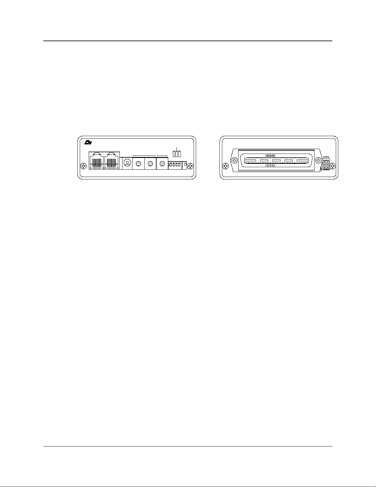
1. Introduction
The Input/Output Control (IOB) is a member of the Monitoring and Control
Network (MCN™) family of auxiliary modules. Hardware specifications, system
examples, and configuration information are provided in this manual.
The IOB module connects I/O devices (such as relays) to the MCN network. The
IOB is used with a User Interface Module (such as a HIB) to create an I/O control
system.
PRODUCTS, INC.
IN
OUTNETWORK
DC IN
9
9
8
8
A
A
7
7
B
B
6
6
C
C
5
5
4
4
D
D
E
E
3
3
F
F
2
2
1
1
0
0
ERR
PWR
MODULEGROUP
9
8
A
7
B
6
C
5
4
D
E
3
F
2
1
0
ON
1234
OPTION
Figure 1 - IOB Front and Rear View
1.1 Reference Documents
1. Monitoring and Control Network System Manual
Part Number S2-60425
2. Monitoring and Control Network Remote Comparator Display Software
Part Number S2-60428
ACT
RESET
J1
E1 A
E1 B
CA-80023-100
68-11168-105
1
Page 7

IOB Hardware Reference Specifications
CTI Products, Inc.
2. Specifications
Size 5.5” x 4.2” x 1.5” (140 x 107 x 38 mm)
Weight 16 oz (455 gm)
Temperature 0 - 50 ºC
Humidity 10 - 95% non-condensing
Module Power 10 - 32 Vdc / 2 Watts max.
Number of Input Points 32 max (depending on the operating mode)
Number of Output Points 16 max (depending on the operating mode)
Open Circuit Voltage (all I/O pins)
jumper E1B removed
jumper E1B installed
Input Voltage (Input pins) -0.6 to 30 Vdc (max)
Input Current (Input pins):
jumper E1B removed (Vin = 0 Vdc)
jumper E1B installed (Vin = 0 Vdc)
Output Saturation Voltage (Output pins)
with Iout = 100 mA
Output Pin Current (Output pins) 150 mA max per individual pin (sink)
Power Dissipation 2 Watts Nominal
Input/Output Connection 50 pin Telco style
Network Connector (2) RJ-45 (1 in, 1 out)
Safety Approvals UL 1950
Emissions Compliance FCC Part 15, Class A
Susceptibility Compliance IEC 801-2
+13.8 Vdc nominal
+5 Vdc nominal
-720 µA max (source)
-270 µA max (source)
550 mV
100 mA max per pin if all outputs are ON.
CSA 1950
EN 60950-1992
DOC Class A
EN55022
IEC 801-3
IEC 801-4
EN50082-1
Table 1 - Module Specifications
2
68-11168-105
Page 8
IOB Hardware Reference Specifications
p
CTI Products, Inc.
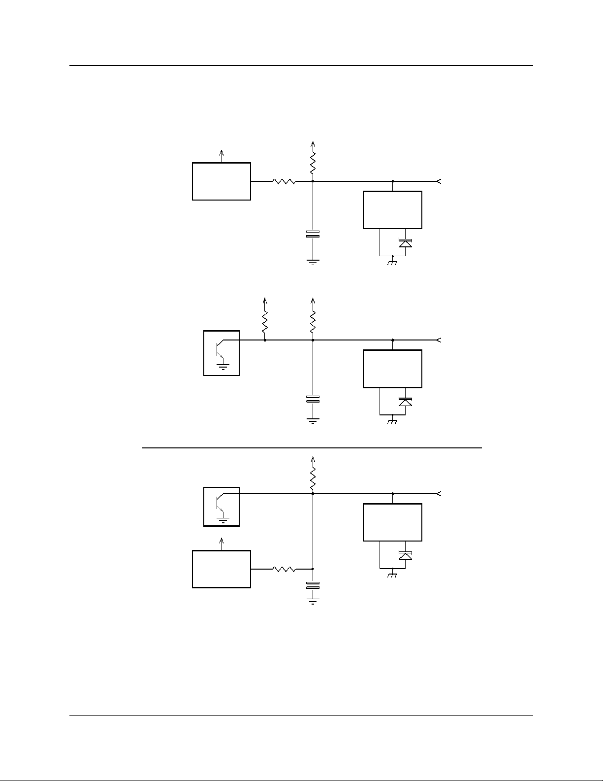
Figure 2 shows the equivalent circuits of the IOB I/O pins. The pull-up voltage
Vp by jumper E1B, located on the rear of the module.
• Vp = 13.8 Vdc with jumper E1B out
• Vp = 5.0 Vdc with jumper E1B in
+5V
HCMOS
IC
INPUT
+5V
150K
180K
INPUT
V
22K
ESD
PROTECTION
0.1uF
Vp
22K
PROTECTION
0.1uF
ESD
30V
TRANSORB
30V
TRANSORB
OUTPUT
Vp
22K
+5V
HCMOS
IC
INPUT
150K
0.1uF
INPUT/OUTPUT
Figure 2 - I/O Equivalent Circuit
ESD
PROTECTION
30V
TRANSORB
CA-80043-100
68-11168-105
3
Page 9

IOB Hardware Reference Theory of Operation
CTI Products, Inc.
3. Theory of Operation
This section describes the operation of the IOB module in an I/O control system.
This module can operate in one of four different modes:
I/O Group Mode 1 Mode 2 Mode 3 Mode 4
1
2 1 of 4 Select 1 of 4 Select
3# 1
4 Independent 1 of 8 Select
5I/O
6 1 of 4 Select Independent
7# 2I/O
8
The operating mode is set using the OPTION switches on the module’s front
panel. Refer to section 4 for a description of the mode setting switches and
section 5 for a pinout of the IOB’s I/O connector. The functions of the I/O
connector pins on the rear of the module change depending on the IOB’s
operating mode.
Each operating mode is discussed in the following sections.
3.1 Controlling the I/O
The MCN HIB module, along with the MCNRCD Remote Comparator Display
program, provides a PC based user interface for the IOB module. Output points
on the IOB can be controlled by either the PC keyboard or mouse. Input points
can be monitored on the screen.
In order to have the MCNRCD software display meaningful I/O status messages,
custom status text categories and custom status messages must be created for your
specific I/O application (see the appendix titled
the Monitoring and Control Network Remote Comparator Display Software
Manual (reference 2) for details about creating custom status messages). These
custom status messages are defined in the file MCNRCD.CFG.
Section 7 provides a number of examples that show how to customize the
MCNRCD display for an IOB module.
3.1.1
Input Monitoring - I/O Groups and I/O Bits
With the MCNRCD software, a single display position on the screen does not
represent a single I/O point. Instead, each display position represents the state of
four I/O points. We refer to the four I/O points that make up a screen display
position as an I/O group (this is similar to the 4 bits, Vote Rx, Disable, and Fail
associated with a receiver in comparator applications using a CIB module).
Changing Status Message Text
in
68-11168-105
4
Page 10

IOB Hardware Reference Theory of Operation
CTI Products, Inc.
An IOB has 8 I/O groups (similar to the 8 receivers per CIB module). Since each
I/O group is represented by four I/O points, a maximum of 32 I/O points can be
displayed per IOB. When configuring your MCNRCD screens for IOB modules,
know that each I/O group is related to an Rx # in the MCNRCD and MCNCFG
software. I/O group 1 is the same as Rx # 1 and so on through I/O group 8 is the
same as Rx # 8.
The basic IOB module is setup as 8 I/O groups. Each I/O group has the following
4 I/O lines:
I/O Bit
#
Type Status Byte
Binary Weight
MCNRCD Input
Status Signal
Output Controlled By
1 Input/Output 01 hex VOTE left mouse button or “V”
2 Input 04 hex RECEIVE N/A
3 Input/Output 10 hex DISABLE right mouse button or “D”
4 Input 40 hex FAIL N/A
Table 2 - I/O Point Binary Weight
Table 2 shows the binary weight of each I/O bit. These binary weights are
summed to create the input value fields of the MCNRCD.CFG text definition
line. This allows you to display up to 16 status message values for each I/O group
(receiver) on the MCNRCD screen. All valid combinations of these binary
weights must be defined by separate text definition lines (again, see the appendix
Changing Status Message Text
titled
in the Monitoring and Control Network
Remote Comparator Display Software Manual (reference 2) for details about
creating custom status messages). Table 3 shows the possible combinations of the
binary weights (in the Input Value Field column) and the I/O bit combinations for
that value. A column has also been provided for you to enter the text
corresponding to the input value field.
In the 1 or 4 and 1 of 8 select configurations, the output for I/O bit 3 is disabled
(only the output for I/O bit 1 can be used).
In all cases, any pin not used as an output can be used as an input. Inputs can be
dynamic inputs used to sense on and off conditions or can be static “selector”
inputs which are permanently strapped to provide a selector function for subcategories.
68-11168-105
5
Page 11

IOB Hardware Reference Theory of Operation
CTI Products, Inc.
Input Value
Field
Active I/O Bit
Combinations
00 01 1
04 2
05 2 + 1
10 3
11 3 + 1
14 3 + 2
15 3 + 2 + 1
40 4
41 4 + 1
44 4 + 2
45 4 + 2 + 1
50 4 + 3
51 4 + 3 + 1
54 4 + 3 + 2
55 4 + 3 + 2 + 1
Table 3 - Input Value Definitions
Custom
Text
Note: The IOB’s inputs and outputs are active low. Therefore, for a I/O bit to be
active, it must be pulled to ground. Also, when an output is active, it is driven
low by the IOB.
68-11168-105
6
Page 12

IOB Hardware Reference Theory of Operation
CTI Products, Inc.
3.1.2
Output Control
As stated earlier in this section, the output points of the IOB module can be
controlled by both the mouse and keyboard. Table 4 shows which I/O bits are
controlled by the specific mouse or keyboard buttons. To control the I/O bit,
simply move the cursor over the I/O group that represents the I/O bit and click the
proper mouse button or press the proper keyboard button. The IOB output point
will change state. The IOB uses the input of the input/output point to
automatically generate feedback to the MCNRCD software so that the new state
of the output is displayed. When using a input/output point as an output, do not
attach any circuitry that can drive the pin. The keyboard and mouse controls can
be setup to provide either a latched output or a momentary output, depending
upon the setting of the VOTE= and DISABLE= definition lines for the
MCNRCD.CFG category you created. Refer to the appendix titled
Status Message Text
in the Monitoring and Control Network Remote Comparator
Changing
Display Software Manual (reference 2) for details about configuring the button
control.
I/O
Bit
Mouse
Control
Keyboard
Control
1 left button V key
3 right button D key
Table 4 - Output Controls
68-11168-105
7
Page 13

IOB Hardware Reference Theory of Operation
CTI Products, Inc.
3.2 Mode 1 - General Purpose I/O - 16 Outputs
In general purpose I/O mode, the IOB module provides 16 input/output lines and
16 input only lines. Table 16 shows the pinout for this mode as well as the I/O
group and I/O bit number associated with each connector pin.
3.3 Mode 2 - Two Sets of 1 of 4 Select Output
In this mode, the IOB provides two sets of 1 of 4 Select output lines and 24 input
only lines. Table 16 shows the pinout for this mode as well as the I/O group and
I/O bit number associated with each connector pin.
Table 5 shows how the 1 of 4 Select outputs operate, allowing only one active
output in each set of 4 Select lines (A, B, C and D). Remember, the outputs are
active low so the output pin for the selected output is low and the output pins of
the other select outputs are high.
Select 1 or Select 2
A B C D
1 0 0 0 Select A
0 1 0 0 Select B
0 0 1 0 Select C
0 0 0 1 Select D
Table 5 - 1 of 4 Select Operation
Note: In this table, any output shown as a 0 is a high output and any output shown
as a 1 is low output.
The IOB has the option to invert the Select A output so that the Select A output
pin is active high and the Select B, C and D output pins are active low. This
operation is shown in Table 6. The Select A invert option is selected with
OPTION switch position 3 (see section 4).
Select 1 or Select 2
A B C D
0 0 0 0 Select A
1 1 0 0 Select B
1 0 1 0 Select C
1 0 0 1 Select D
selected
output
selected
output
Table 6 - Inverted Select A Operation
Note: In this table, any output shown as a 0 is a high output and any output
shown as a 1 is low output.
68-11168-105
8
Page 14

IOB Hardware Reference Theory of Operation
CTI Products, Inc.
This option is typically used when you need 1 of 4 relays that will operate in a
fail-safe mode when the power fails. For instance, you can drive 4 DPDT relays
to provide a 1 of 4 manual transmitter selection circuit. Transmitters 2 through 4
would be connected to the normally open relay contacts, while transmitter 1
would be connected to the normally closed contacts. If the power fails, the system
will revert to transmitter 1.
3.4 Mode 3 - One Set of 1 of 4 Select Outputs
+ 8 Independent Outputs
In this mode, the IOB provides one bank of 1 of 4 Select output lines, 8
input/output lines and 20 input only lines. Table 16 shows the pinout for this
mode as well as the I/O group and I/O bit number associated with each connector
pin.
The first 4 I/O groups are used as 1 of 4. I/O groups 5 through 8 are independent
I/Os. The operation of the first 4 I/O groups is the same as Mode 2.
3.5 Mode 4 - One Set of 1 of 8 Select Outputs
In this mode, the IOB provides a 1 of 8 Select output and 24 input only lines.
Table 16 shows the pinout for this mode as well as the I/O group and I/O bit
number associated with each connector pin.
Table 7 shows how the 1 of 8 Select outputs operate, allowing only one active
output in each the of 8 Select lines (A through H).
Select
A B C D E F G H
1 0 0 0 0 0 0 0 Select A
0 1 0 0 0 0 0 0 Select B
0 0 1 0 0 0 0 0 Select C
0 0 0 1 0 0 0 0 Select D
0 0 0 0 1 0 0 0 Select E
0 0 0 0 0 1 0 0 Select F
0 0 0 0 0 0 1 0 Select G
0 0 0 0 0 0 0 1 Select H
Table 7 - 1 of 8 Select Operation
selected output
Note: In this table, any output shown as a 0 is a high output and any output shown
as a 1 is low output.
The IOB has the option to invert the Select A output so that the Select A output
pin is active high and the Select B, C and D output pins are active low. This
68-11168-105
9
Page 15

IOB Hardware Reference Theory of Operation
CTI Products, Inc.
operation is shown in Table 8. The Select A invert option is selected with
OPTION switch position 3 (see section 4).
Select
A B C D E F G H
0 0 0 0 0 0 0 0 Select A
1 1 0 0 0 0 0 0 Select B
1 0 1 0 0 0 0 0 Select C
1 0 0 1 0 0 0 0 Select D
1 0 0 0 1 0 0 0 Select E
1 0 0 0 0 1 0 0 Select F
1 0 0 0 0 0 1 0 Select G
1 0 0 0 0 0 0 1 Select H
Table 8 - Inverted Select A Operation
Note: In this table, any output shown as a 0 is a high output and any output shown
as a 1 is low output.
This can be used to drive fail-safe relays as described in Mode 2.
3.6 Custom Status Text Sub-categories
It is possible to connect different types of I/O devices (like main/standby relays
and lighting control) to a single IOB module. This is done by creating subcategories within a single category in the MCNRCD.CFG file. To create a subcategory, you need to reserve one or more of the input signals in each I/O group of
the IOB module for the sub-category selector. These reserved bits are then either
left floating or strapped to ground to define the possible sub-categories. The
appendix titled
Network Remote Comparator Display Software Manual (reference 2) has
additional information about sub-categories.
Changing Status Message Text
in the Monitoring and Control
selected
output
When you reserve an input signal for a sub-category selector, you are also
reserving the I/O bit associated with that input signal. The reserved I/O bits are
then used to define the sub-categories in the MCNRCD.CFG file. The following
sections show how the multiple sub-categories can be created by reserved 1, 2 or 3
I/O bits for the sub-category selector.
Section 7.4 has a system example that defines two sub-categories.
68-11168-105
10
Page 16

IOB Hardware Reference Theory of Operation
CTI Products, Inc.
Creating Two Sub-categories
To create two sub-categories, one I/O bit must be reserved for the sub-category
selector. In Table 9, I/O bit 4 has been reserved for the sub-category selector.
You can see from the table that there are eight possible status messages that can
be defined for each sub-category. Because I/O bit 4 has been reserved as the
selector, all IOB pins that correspond to I/O bit 4 cannot be used by application
circuitry.
Sub-category
Input Value
Field
Sub-
category
#
Selector I/O
Bit
4
I/O Bit
Combinations
3 2 1
00 1 0 0 0 0
01 1 0 0 0 1
04 1 0 0 1 0
05 1 0 0 1 1
10 1 0 1 0 0
11 1 0 1 0 1
14 1 0 1 1 0
15 1 0 1 1 1
40 2 1 0 0 0
41 2 1 0 0 1
44 2 1 0 1 0
45 2 1 0 1 1
50 2 1 1 0 0
51 2 1 1 0 1
54 2 1 1 1 0
55 2 1 1 1 1
Table 9 - 2 Sub-categories / 8 States
Note: In this table, any I/O bit shown as a 0 is a floating input or a high output
and any I/O bit shown as a 1 is an input tied to ground or a low output.
68-11168-105
11
Page 17

IOB Hardware Reference Theory of Operation
CTI Products, Inc.
Creating Four Sub-categories
To create four sub-categories (for four different I/O types), two I/O bits must be
reserved for the sub-category selector. In Table 10, I/O bits 3 and 4 have been
reserved for the sub-category selector. You can see from the table that there are
four possible status messages that can be defined for each sub-category. Because
I/O bits 3 and 4 have been reserved as the selector, all IOB pins that correspond to
I/O bits 3 and 4 in all I/O groups cannot be used by application circuitry.
Warning: Because I/O bit 3 is used as a sub-category selector, you must make
sure that the mouse and keyboard button cannot change the state of the I/O pins
corresponding to I/O bit 3. Therefore, in your category definition, make sure the
DISABLE=x line state the following:
DISABLE=O
This line will turn off the right mouse button and the ‘D’ keyboard key so that I/O
bit 3 cannot be controlled from the keyboard.
Sub-category
Input Value
Field
Sub-
category
#
Selector I/O
Bits
4 3
I/O Bit
Combinations
2 1
00 1 0 0 0 0
01 1 0 0 0 1
04 1 0 0 1 0
05 1 0 0 1 1
10 2 0 1 0 0
11 2 0 1 0 1
14 2 0 1 1 0
15 2 0 1 1 1
40 3 1 0 0 0
41 3 1 0 0 1
44 3 1 0 1 0
45 3 1 0 1 1
50 4 1 1 0 0
51 4 1 1 0 1
54 4 1 1 1 0
55 4 1 1 1 1
Table 10 - 4 Sub-categories / 4 States
Note: In this table, any I/O bit shown as a 0 is a floating input or a high output
and any I/O bit shown as a 1 is an input tied to ground or a low output.
68-11168-105
12
Page 18

IOB Hardware Reference Theory of Operation
CTI Products, Inc.
Creating Eight Sub-categories
To create eight sub-categories, three I/O bits must be reserved for the sub-category
selector. In Table 10, I/O bits 2, 3 and 4 have been reserved for the sub-category
selector. You can see from the table that there are two possible status messages
that can be defined for each sub-category. Because I/O bits 2, 3 and 4 have been
reserved as the selector, all IOB pins that correspond to I/O bits 2, 3 and 4 cannot
be used by application circuitry.
Warning: Because I/O bit 3 is used as a sub-category selector, you must make
sure that the mouse and keyboard button cannot change the state of the I/O pins
corresponding to I/O bit 3. Therefore, in your category definition, make sure the
DISABLE=x line state the following:
DISABLE=O
This line will turn off the right mouse button and the ‘D’ keyboard key so that I/O
bit 3 cannot be controlled from the keyboard.
Input Value
Field
Sub-
category
#
Sub-category
Selector I/O Bits
4 3 2
00 1 0 0 0 0
01 1 0 0 0 1
04 2 0 0 1 0
05 2 0 0 1 1
10 3 0 1 0 0
11 3 0 1 0 1
14 4 0 1 1 0
15 4 0 1 1 1
40 5 1 0 0 0
41 5 1 0 0 1
44 6 1 0 1 0
45 6 1 0 1 1
50 7 1 1 0 0
51 7 1 1 0 1
54 8 1 1 1 0
55 8 1 1 1 1
I/O Bit
Combinations
1
Table 11 - 8 Sub-categories / 2 States
Note: In this table, any I/O bit shown as a 0 is a floating input or a high output
and any I/O bit shown as a 1 is an input tied to ground or a low output.
68-11168-105
13
Page 19

IOB Hardware Reference Option Switches and Jumpers
CTI Products, Inc.
4. Option Switches and Jumpers
Three sets of option switches are provided for module configuration. The module
must be power cycled or reset after these switches are set so that the options will
take effect. Table 12 describes the option switches and shows the factory defaults.
SWITCH DESCRIPTION DEFAULT
GROUP Unit Address Setting
refer to the MCN System Manual
MODULE Unit Address Setting
refer to the MCN System Manual
OPTION
position 1 Mode Select 1 (see Table 13) DOWN
position 2 Mode Select 2 (see Table 13) DOWN
position 3 Select A Invert DOWN
position 4 I/O Scan Rate Select DOWN
Table 12 - IOB Option Switches
00
0
The Group and Module selector switches are used to set the unit address during
module installation. Refer to reference 1, the Monitoring and Control Network
System Manual, for details about setting these switches.
The mode select switches (OPTION switch positions 1 and 2) set the operating
mode of the IOB. Refer to section 3 for a description of the various operating
modes available. Table 13 provides for a description of these switches.
Option Switch Position
1 2
DOWN DOWN 1 General I/O
UP DOWN 2 2 sets of 1 of 4 Select Outputs
DOWN UP 3 1 set of 1 of 4 Select Outputs + 8
UP UP 4 1 set of 1 of 8 Select Outputs
Table 13 - IOB Operating Mode Selector Switches
Mode
Number Selected Mode
Independent Outputs
14
68-11168-105
Page 20

IOB Hardware Reference Option Switches and Jumpers
CTI Products, Inc.
The Select A Invert switch (OPTION switch position 3) is only used when
operating modes 2, 3 or 4 are selected (in mode 1, this switch is not used). The
switch is defined as:
Option Switch 3 Function
DOWN Inverted Select A Outputs (active low)
UP Normal Select A Outputs (active high)
This switch only affects the Select A output lines. All other Select output lines
are active low. Refer to section 3 for a discussion of each operating mode.
The I/O Scan Rate Select switch (OPTION switch position 4) is used to select the
I/O scan rate for the IOB module. The switch is defined as:
Option Switch 4 Function
DOWN Normal scan rate (3 times per second)
UP Fast scan rate (10 times per second)
The default position for this switch is DOWN, selecting an I/O scan rate of 3
times per second. For special applications, you may want to increase the scan rate
to the fast scan rate (10 scans of the I/O per second). This allows the IOB module
to detect inputs that are changing more than 3 times per second. The disadvantage
of using the fast scan rate is that the IOB module can generate more network
traffic since it will transmit a network message every time it detects an input
change. With the fast scan rate selected, the IOB module could generate 10
messages per second, instead of 3 messages per second when using the normal
scan rate. If an IOB module is generating more than 3 messages per second, you
may see overall system performance problems (such as slower system response or
missed events on other MCN modules) because other MCN modules may not be
able to communicate over the network as often. Therefore, if you have IOBs in
your system that are set to the fast scan rate, and you begin to experience slow
system response or missed events on other MCN modules, you will have to
change your IOBs to normal scan rate.
Jumper Options
Figure 3 shows the configuration of the two jumper options available on the rear
of the IOB. These jumpers should be installed at system installation time with
power removed from the IOB.
15
68-11168-105
Page 21

IOB Hardware Reference Option Switches and Jumpers
CTI Products, Inc.
E1 A
E1 B
CA-80024-100
Figure 3 - Jumper Options
Jumper E1A is located across the top 2 terminals of the 6 pin terminal block. This
jumper is reserved and should not be installed.
Jumper E1B is located across the left side middle and bottom terminals of the 6
pin terminal block. Set this jumper to match the needs of your I/O system.
The remaining 2 terminals of the block are unused.
Jumper Function Default
E1A Reserved OUT
E1B
Vp Set
In for inputs pulled up to +5 Vdc.
Out for inputs pulled up to +13.8 Vdc.
OUT
Table 14 - Jumper Definitions
Because most installations require the pull-up voltage to be +13.8 Vdc, no jumper
is provided with the unit for the E1B jumper terminals. If you have an application
that requires the pull-up voltage to be set to +5 Vdc, you can order an additional
jumper by calling CTI Products Inc. and ordering part number
27-10351.
16
68-11168-105
Page 22

IOB Hardware Reference Connectors
CTI Products, Inc.
5. Connectors
The NETWORK IN/OUT ports on the front of the IOB are used to connect the
IOB with other MCN modules. These ports carry both the network data signals as
well as DC power for power distribution with other modules. . Table 15 gives the
pinout for these connectors. Figure 4 shows the location of pin 1 for each port.
PRODUCTS, INC.
NETWORK
IN
PIN 1
OUT
DC IN
CA-80068-100
Figure 4 - Network IN/OUT Ports
Pin Function
1 DATA +
2 DATA 3+ POWER
4 No Connect
5 No Connect
6- POWER
7- POWER
8+ POWER
Table 15 - Network Connector Pinout
The DC IN port provides the primary power connection to the module. Power is
distributed through the NETWORK OUT connector to provide power to the
NETWORK IN connector of the MCN unit it is connected to. Each power
supply can power up to four units total. See the Monitoring and Control Network
System Manual (reference 1) for complete details of connections to the network
and DC IN connectors.
Connector J1 provides the discrete I/O points. The pin definitions for this
connector change, depending upon which operating mode the IOB module is set
for. Table 16 gives the pin numbers and their definitions for each mode. The
column labeled I/O bit includes, in parenthesis, the MCNRCD name associated
with the bit number. Table 17 gives this same information, but the order of the
IOB pin numbers matching a punch block pinout. See the appendix titled
68-11168-105
17
Page 23

IOB Hardware Reference Connectors
CTI Products, Inc.
Changing Status Message Text
in the Monitoring and Control Network Remote
Comparator Display Software Manual (reference 2) for more information about
custom text messages.
Mode 1
IOB
Pin
#
21 input/output 1 Select 1A output Select 1A output Select 1A output 1 1 (VOTE)
46 input/output 2 Select 1B output Select 1B output Select 1B output 2 1 (VOTE)
15 input/output 3 Select 1C output Select 1C output Select 1C output 3 1 (VOTE)
40 input/output 4 Select 1D output Select 1D output Select 1D output 4 1 (VOTE)
9 input/output 5 Select 2A output input/output 5 Select 1E output 5 1 (VOTE)
34 input/output 6 Select 2B output input/output 6 Select 1F output 6 1 (VOTE)
3 input/output 7 Select 2C output input/output 7 Select 1G output 7 1 (VOTE)
28 input/output 8 Select 2D output input/output 8 Select 1H output 8 1 (VOTE)
22 input 1 input 1 input 1 input 1 1 2 (RECEIVE)
47 input 2 input 2 input 2 input 2 2 2 (RECEIVE)
16 input 3 input 3 input 3 input 3 3 2 (RECEIVE)
41 input 4 input 4 input 4 input 4 4 2 (RECEIVE)
10 input 5 input 5 input 5 input 5 5 2 (RECEIVE)
35 input 6 input 6 input 6 input 6 6 2 (RECEIVE)
4 input 7 input 7 input 7 input 7 7 2 (RECEIVE)
29 input 8 input 8 input 8 input 8 8 2 (RECEIVE)
20 input/output 9 input/output 9 * input/output 9 * input/output 9 * 1 3 (DISABLE)
45 input/output 10 input/output 10 * input/output 10 * input/output 10 * 2 3 (DISABLE)
14 input/output 11 input/output 11 * input/output 11 * input/output 11 * 3 3 (DISABLE)
39 input/output 12 input/output 12 * input/output 12 * input/output 12 * 4 3 (DISABLE)
8 input/output 13 input/output 13 * input/output 13 input/output 13 * 5 3 (DISABLE)
33 input/output 14 input/output 14 * input/output 14 input/output 14 * 6 3 (DISABLE)
2 input/output 15 input/output 15 * input/output 15 input/output 15 * 7 3 (DISABLE)
27 input/output 16 input/output 16 * input/output 16 input/output 16 * 8 3 (DISABLE)
23 input 9 input 9 input 9 input 9 1 4 (FAIL)
48 input 10 input 10 input 10 input 10 2 4 (FAIL)
17 input 11 input 11 input 11 input 11 3 4 (FAIL)
42 input 12 input 12 input 12 input 12 4 4 (FAIL)
11 input 13 input 13 input 13 input 13 5 4 (FAIL)
36 input 14 input 14 input 14 input 14 6 4 (FAIL)
5 input 15 input 15 input 15 input 15 7 4 (FAIL)
30 input 16 input 16 input 16 input 16 8 4 (FAIL)
1 Ground Ground Ground Ground
(32) General
Purpose I/O
Mode 2
(2) One-of-Four
Select Outputs
Mode 3
(1) One-of-Four
Select Outputs +
8 Independent
Outputs
Mode 4
One of Eight
Select Outputs
I/O
Group #
I/O Bit #
Table 16 - Connector J1 Pinout
* These pins are treated as “input only” when in the specific mode. The output
control of these pins has been disabled.
68-11168-105
18
Page 24

IOB Hardware Reference Connectors
CTI Products, Inc.
IOB
Pin
26
1 Ground Ground Ground Ground
27 input/output 16 input/output 16 * input/output 16 input/output 16 * 8 3 (DISABLE)
2 input/output 15 input/output 15 * input/output 15 input/output 15 * 7 3 (DISABLE)
28 input/output 8 Select 2D output input/output 8 Select 1H output 8 1 (VOTE)
3 input/output 7 Select 2C output input/output 7 Select 1G output 7 1 (VOTE)
29 input 8 input 8 input 8 input 8 8 2 (RECEIVE)
4 input 7 input 7 input 7 input 7 7 2 (RECEIVE)
30 input 16 input 16 input 16 input 16 8 4 (FAIL)
5 input 15 input 15 input 15 input 15 7 4 (FAIL)
31
6
32
7
33 input/output 14 input/output 14 * input/output 14 input/output 14 * 6 3 (DISABLE)
8 input/output 13 input/output 13 * input/output 13 input/output 13 * 5 3 (DISABLE)
34 input/output 6 Select 2B output input/output 6 Select 1F output 6 1 (VOTE)
9 input/output 5 Select 2A output input/output 5 Select 1E output 5 1 (VOTE)
35 input 6 input 6 input 6 input 6 6 2 (RECEIVE)
10 input 5 input 5 input 5 input 5 5 2 (RECEIVE)
36 input 14 input 14 input 14 input 14 6 4 (FAIL)
11 input 13 input 13 input 13 input 13 5 4 (FAIL)
37
12
38
13
39 input/output 12 input/output 12 * input/output 12 * input/output 12 * 4 3 (DISABLE)
14 input/output 11 input/output 11 * input/output 11 * input/output 11 * 3 3 (DISABLE)
40 input/output 4 Select 1D output Select 1D output Select 1D output 4 1 (VOTE)
15 input/output 3 Select 1C output Select 1C output Select 1C output 3 1 (VOTE)
41 input 4 input 4 input 4 input 4 4 2 (RECEIVE)
16 input 3 input 3 input 3 input 3 3 2 (RECEIVE)
42 input 12 input 12 input 12 input 12 4 4 (FAIL)
17 input 11 input 11 input 11 input 11 3 4 (FAIL)
43
18
44
19
45 input/output 10 input/output 10 * input/output 10 * input/output 10 * 2 3 (DISABLE)
20 input/output 9 input/output 9 * input/output 9 * input/output 9 * 1 3 (DISABLE)
46 input/output 2 Select 1B output Select 1B output Select 1B output 2 1 (VOTE)
21 input/output 1 Select 1A output Select 1A output Select 1A output 1 1 (VOTE)
47 input 2 input 2 input 2 input 2 2 2 (RECEIVE)
22 input 1 input 1 input 1 input 1 1 2 (RECEIVE)
48 input 10 input 10 input 10 input 10 2 4 (FAIL)
23 input 9 input 9 input 9 input 9 1 4 (FAIL)
49
24
50
25
Mode 1 Mode 2 Mode 3 Mode 4 I/O Group
#
I/O Bit #
Table 17 - Connector J1 Pinout in Punch Block Order
19
68-11168-105
Page 25

IOB Hardware Reference Mounting
CTI Products, Inc.
6. Mounting
Refer to the Monitoring and Control Network System Manual (reference 1),
section
Make sure that any mounting screws used to secure unit to a bracket do not
protrude into the unit’s enclosure more than 1/8 inches from the bottom surface of
the unit.
Using a larger screw that touches the pc board inside the unit may damage the unit
when it is powered. Doing so will void the unit’s warranty.
Mounting Options,
for details about mounting the IOB module.
CAUTION
20
68-11168-105
Page 26

IOB Hardware Reference System Examples
CTI Products, Inc.
7. System Examples
This section contains various examples that describe the different operating modes
of the IOB module.
7.1 General Purpose I/O Example
Figure 5 shows a general purpose I/O system that is monitored from a local PC.
USER APPLICATIONIOB
CIRCUIT
I/O BIT
CIRCUIT
(OUTPUT)
(INPUT)
(OUTPUT)
(INPUT)
CA-80277-100
I/O GROUP
1-8
1
2
3
4
RUN
ACTIVE
STEP
FAIL
Figure 5 - I/O Group Configuration
For this application, we will need to create a custom status text category in the
MCNRCD.CFG file so that the MCNRCD software can display meaningful status
messages. Before editing the MCNRCD.CFG file, we need to define our custom
text messages. Table 18 shows the functions for each I/O bit.
I/O Bit # Function Binary Weight
1 Run 01 hex
2 Active 04 hex
3 Step 10 hex
4 Fail 40 hex
Table 18 - Example System Text Definition
Next we need to create a custom text table for all possible input value field
combinations. Table 19 shows the custom text messages and the corresponding
input value fields.
68-11168-105
21
Page 27

IOB Hardware Reference System Examples
CTI Products, Inc.
Input Value
Field
Active I/O Bit
Combinations
Custom
Text
00 01 1 Run
04 2 Active
05 2 + 1 Run/Act
10 3 Step
11 3 + 1 Run/Step
14 3 + 2 Step/Act
15 3 + 2 + 1 Run/Act
40 4 Fail
41 4 + 1 Fail/Run
44 4 + 2 Fail
45 4 + 2 + 1 Fail/Run
50 4 + 3 Fail/Step
51 4 + 3 + 1 Fail
54 4 + 3 + 2 Fail/Step
55 4 + 3 + 2 + 1 Fail
Table 19 - Custom Text for General I/O System
From this table we can now create our custom status text category in the
MCNRCD.CFG file. Refer to the appendix in the Monitoring and Control
Network Remote Comparator Display Software Manual (reference 2) titled
Changing Status Message Text
for details about the format of the MCNRCD.CFG
file.
22
68-11168-105
Page 28

IOB Hardware Reference System Examples
CTI Products, Inc.
7.2 One of Four Select I/O Example
Figure 6 shows an I/O system that uses the IOB in 1 of 4 Select mode. The four
Select outputs are connected to relay controls and the four PTT inputs are
connected to input pins of the IOB.
LOCAL PC
T
COM 2
COM 1
HIB
P/S
IN
OUT
T
OUT
IN
IOB
CIRCUIT
USER APPLICATIONIOB
CIRCUIT
TX 1 SELECT
TX 2 SELECT
TX 3 SELECT
TX 4 SELECT
PTT1
PTT2
PTT3
PTT4
CA-80258-100
Figure 6 - 1 of 4 Select System Example
Just as in the previous example, we need to create a custom status text category
for this IOB. Before creating the status text messages, we should look at how
each I/O group will be configured. Figure 7 shows the I/O bit configuration for
each of the four I/O groups being used.
68-11168-105
23
Page 29

IOB Hardware Reference System Examples
CTI Products, Inc.
USER APPLICATION
CIRCUIT
TX SELECT
PTT
NO CONNECT
NO CONNECT
(OUTPUT)
(INPUT)
CA-80276-100
I/O GROUP
1-4
IOB
CIRCUIT
I/O BIT
1
2
3
4
Figure 7 - 1 of 4 Select I/O Bit Configuration (Tx Select and PTT)
From the figure, you can see that relay control lines are connected to the Select 1A
through D outputs of the IOB. These outputs correspond to I/O bit 1 of I/O
groups 1 through 4 . The PTT inputs are connected to four input lines of the IOB,
which correspond to I/O group bits 2 (RECEIVE) and 4 (FAIL) of I/O groups 5
through 8.
Before editing the MCNRCD.CFG file, we need to define our custom text
messages. Let’s define the status messages for the active Select output line to be
the text Active and the status messages for the active input lines to be Tx. Now
we can create a custom text table for all possible input value field combinations.
Table 20 shows the custom text messages and the corresponding input value
fields.
Input Value
Field
Active I/O Bit
Combinations
Custom
Text
00 01 1 Active
04 2 Tx
05 1 + 2 Act/Tx
Table 20 - 1 of 4 Select Example Custom Text
From this table we can now create our custom status text category in the
MCNRCD.CFG file. Refer to the appendix in the Monitoring and Control
Network Remote Comparator Display Software Manual (reference 2) titled
Changing Status Message Text
for details about the format of the MCNRCD.CFG
file.
68-11168-105
24
Page 30

IOB Hardware Reference System Examples
CTI Products, Inc.
7.3 Inverted Select A Example
For this example, assume we have the same system as in section 7.2, but we need
to changed the system so that the TX 1 Select relay is normally closed (so that if
the power fails, the TX 1 Select relay will be engaged). Figure 8 shows this
modified system drawing.
LOCAL PC
T
COM 2
COM 1
HIB
P/S
IN
OUT
T
OUT
IN
IOB
Figure 8 - Inverted Select A Example
IOB
CIRCUIT
USER APPLICATION
CIRCUIT
TX 1 SELECT
TX 2 SELECT
TX 3 SELECT
TX 4 SELECT
CA-80223-100
PTT1
PTT2
PTT3
PTT4
Because the Select 1A output is connected to a normally closed relay, we need the
Select 1A output to operate as an active high output instead of active low. The
Select 1A output should be high when the Select 1A output is not the selected
output and low when the Select 1A output is the selected output. The OPTION
switch position 3 needs to be placed in the UP position to enable the inverted
Select A output mode (the module must be reset or power cycled after the switch
is changed).
The system in Figure 8 operates the same as the system in section 7.2
68-11168-105
25
Page 31

IOB Hardware Reference System Examples
CTI Products, Inc.
7.4 Sub-category Example
Figure 9 shows a system that uses a single IOB module to monitor two different
types of input devices. One set of input devices are alarm input and the other set
of input devices are control inputs.
Because the IOB is monitoring two different input device types, we need to divide
the IOB’s status text category in the MCNRCD.CFG file into two sub-categories
so that meaningful status messages can be displayed for either type of input
device. Before defining our custom text messages, let’s look at the configurations
for the two I/O groups. This is shown in Figure 9.
USER APPLICATIONIOB
CIRCUIT
I/O BIT
CIRCUIT
ALARM
I/O GROUP
CONTROL
I/O GROUP
1
2
3
4
I/O BIT
1
2
3
4
ALARM
ACTIVE
FAIL
NO CONNECT
ON
OFF
FULL
SUB-CATEGORY
SELECTOR BIT
Figure 9 - Alarm and Control I/O Group Configurations
SUB-CATEGORY
SELECTOR BIT
CA-80275-100
26
68-11168-105
Page 32

IOB Hardware Reference System Examples
CTI Products, Inc.
Since there are two sub-categories defined in this system, we need to reserve one
of the I/O bits for the sub-category selector. Figure 9 shows that I/O bit 4 (FAIL)
is reserved for the sub-category selector. Because I/O bit 4 is reserved, we cannot
use any IOB I/O pins that correspond to I/O bit 4 (see Table 16) as general
purpose I/O pins. Table 21 shows how the sub-category selector bit operates.
I/O Bit 4 Sub-category
0Alarm
1 Control
Table 21 - Sub-category Selection
When I/O bit 4 is inactive (the input is floating), the Alarm sub-category text is
selected and when it is active (the input is tied to ground), the Control subcategory is selected.
Using the I/O group definitions shown in Figure 9, we can create a custom text
table for all possible input value field combinations. Table 22 shows the custom
text messages and the corresponding input value fields.
Input Value
Field
Active I/O Bit
Combinations
Custom
Text
00 01 1 Alarm
04 2 Active
05 2 + 1 Act/Alrm
10 3 Fail
11 3 + 1 Fail
14 3 + 2 Fail
15 3 + 2 + 1 Fail
40 4
41 4 + 1 On
44 4 + 2 Off
45 4 + 2 + 1 Error
50 4 + 3 Full
51 4 + 3 + 1 Full/On
54 4 + 3 + 2 Full/Off
55 4 + 3 + 2 + 1 Error
Table 22 - Custom Text for Sub-category System
From this table we can now create our custom status text category in the
MCNRCD.CFG file. Refer to the appendix in the Monitoring and Control
Network Remote Comparator Display Software Manual (reference 2) titled
Changing Status Message Text
for details about the format of the MCNRCD.CFG
file.
68-11168-105
27
Page 33

IOB Hardware Reference Troubleshooting
CTI Products, Inc.
8. Troubleshooting
This table is a list of troubleshooting tips specific to the IOB module. For
additional troubleshooting tips, refer to the troubleshooting section found in the
Monitoring and Control Network System Manual (reference 1).
Due to the high percentage of surface-mount components the IOB is treated as a
field replaceable unit. If any system problems are the result of a malfunctioning
IOB unit, the entire unit must be replaced and returned for repair.
PROBLEM CAUSE
ERR LED is ON Verify that the IOB’s Group and Module switches are set to valid
numbers.
The wrong status
messages are being
displayed for my custom
category
I have defined subcategories in my system,
but the status messages
being displayed are not
correct
Verify that the application circuits are connected to the proper IOB
pins and that the input value fields of your MCNRCD.CFG file match
your I/O bit assignments for the application circuits.
Verify that the sub-category selector pins are set to the proper state
(inactive pins should be left as no connect, and active pins should be
tied to ground).
28
68-11168-105
 Loading...