

Page 1

HIB-IP & HIB-IP 8000
Remote Network Interfaces
MCN
Monitoring and Control Network
Hardware Reference M anu al
S2-61173-122
68-11827-122
Page 2

CTI Products, Inc. HIB-IP & HIB-IP 8000 Hardware Reference Manual
Standard Limited Har dware Warranty
LIMITED WARRANTY. Equipment manufactured by CTI Products, Inc. is warranted to be free from defects in material and workma nship for
a period of ONE (1) YEAR from date of shipment to original purchaser. Under this warranty, our obligation is limited to repairing or replacing
any equipment proved to be defective by our inspection within one year of sale to the original purchaser. This warranty shall not apply to
equipment which has been repaired outside our plant in any way, so as to, in the judgment of CTI Products, Inc. affect its stability or reliability,
nor which has been operated in a manner exceeding its specifications, nor which has been altered, defaced, or damaged by lightning.
CUSTOMER REMEDIES. In the event of a defect, malfunction, or failure to conform to specifications established by the seller during the
period shown, the customer shall call CTI Products, Inc. to obtain a Return Authorization Number and return the product or module, shipping and
insurance prepaid. CTI Products, Inc., will then at its option, either repair or replace the product or module and return it, shipping prepaid, or
refund the purchase price thereof. On-site labor at the purchaser's location is not included in this warranty.
EQUIPMENT NOT MANUFACTURED BY CTI Produ cts, Inc. Equipment not manufactured by CTI Products, Inc. is excluded from this
warranty, but is subject to the warranty provided by its manufacturer, a copy of which will be supplied to you upon specific written request.
NO OTHER WARRANTIES. The forego ing constitutes the s o le and exclusiv e r emedy of the b uyer and exclusive liability of CTI Products,
Inc., AND IS IN LIEU OF ANY AND ALL OTHER WARRANTIES EXPRESSED OR IMPLIED OR STATUTORY AS TO
MERCHANTABILITY, FITNESS FOR PUR P OSE SOLD, DESCRIPTION, QUALITY, PRODUCTIVENESS OR ANY OTHER M ATTER .
NO LIABILITY FOR CONSEQUENTIAL DAMAGES. WITHOUT LIMIT ING THE FOREGOING, IN NO EVENT SHALL CTI
PRODUCTS, INC. OR ITS SUPPLIERS BE LIABLE FOR ANY DAMAGES WHATSOEVER (INCLUDING, WITHOUT LIMITATION,
SPECIAL, INCIDENTAL OR CONSEQUENTIAL DAMAGES OR FOR LOSS OF BUSINESS PROFITS, BUSINESS INTERRUPTION,
LOSS OF BUSINESS INFORMATION, OR OTHER PECUNIARY LOSS) AR IS ING OUT OF THE USE OF OR INABILITY TO USE CTI
PRODUCTS, INC. EQUIPMENT BY PURCHASER OR OTHER THIRD PARTY, WHETHER UNDER THEORY OF CONTRACT, TORT
(INCLUDING NEGLIGENCE), INDEMNITY, PR ODUCT LIABILITY OR OTHERWISE, EVEN IF CTI PRODUCTS, INC. HAS BEEN
ADVISED OF THE POSSIBILITY OF SUCH DAMAGES OR LOSSES. IN NO EVENT SHALL CTI PRODUCTS, INC.’S, LIABILITY
EXCEED THE TOTAL AMOUNT PAID BY PURCHASER FOR THE EQUIPME NT GIVING RISE TO SUCH LIABILITY.
Location: CTI Products, Inc
1211 West Sharon Road
Cincinnati, OH 45240 USA
Phone: +1.513.595.5900
Fax: +1.513.595.5983
Web: www.ctiproducts.com
E-mail, Sales: info@ctiproducts.com
Technical Support: support@ctiproducts.com
Information contained in this document is subject to change without notice and does not represent a commitment on the part of CTI
Products, Inc. No part of this manual may be reproduced or transmitted in any form or by any means, electronic or mechanical, including
photocopying and recording, for any purpose without the written permission of CTI Products, Inc.
This manual describes pro ducts which include copyrighted CTI Products, Inc. computer programs in semiconductor memory. CTI
Products, Inc. reserves all rights for these programs, including the exclusive right to copy or reproduce the copyrighted computer programs
in any form. No copyrighted computer program contained in products described in this manual may be copied, reproduced, decompiled,
disassembled, or reversed engineered in any manner without express written permission of CTI Products, Inc. The purchase of products
from CTI Products, Inc. shall not be deemed to grant ei ther directly or by impli cation, estoppel, or other wi se, any license under the
copyrights, paten ts, or patent applications of CTI Products, Inc., except for the normal non-exclusive, royalty fee license to use that arises
by operation of law in the s ale of the product.
Copyright (c) 2004-2012 CTI Products, Inc. All rights reserved
HIB, HIB-IP, EXB, EXB-IP, MCN, MCN Server 8000 and MCNRCD are trademarks of CTI Products, Inc.
ASTRO, MOTOROLA, and MOTOROLA SOLUTIONS a nd the Stylized M Logo are trademarks or registered trad emarks of Motorola
Trademark Holdings, LLC.
68-11827-122
Page 3

CTI Products, Inc. HIB-IP & HIB-IP 8000 Hardware Reference Manual
TABLE OF CONTENTS
1. INTRODUCTION ................................................................................................................................................... 5
WHAT IS A HIB-IP? .................................................................................................................................................... 5
REFERENCE DOCUMENTS ........................................................................................................................................... 6
FRONT PANEL ............................................................................................................................................................. 7
REAR PANEL............................................................................................................................................................... 8
2. IP ADDRESS CONFIGURATION ...................................................................................................................... 10
MCN CONFIG SOFTWARE ........................................................................................................................................ 10
IP SETTINGS WORKSHEET ........................................................................................................................................ 11
BACKUP & RESTORE PROCEDURES .......................................................................................................................... 12
SECURITY AND INFORMATION ASSURANCE RECOMMENDATIONS ............................................................................ 12
3. INSTALLATIO N ................................................................................................................................................... 13
PHYSICALLY INSTALL HIB-IP UNIT ONTO THE IP NETWORK ................................................................................... 13
4. TESTING ............................................................................................................................................................... 17
HTTP STATUS PAGE ................................................................................................................................................ 17
PINGING THE HIB-IP UNIT ....................................................................................................................................... 18
APPENDIX ................................................................................................................................................................ 19
APPENDIX A. FACTORY DEFAULT CONFIGURATION ................................................................................................. 19
APPENDIX B. MOUNTING OPTIONS ........................................................................................................................... 20
APPENDIX C. CONNECTOR DETAILS ......................................................................................................................... 23
APPENDIX D. HIB-IP PROGRAMMING CABLE PINOUT 89-11314 .............................................................................. 25
APPENDIX E. TROUBLESHOOTING ............................................................................................................................ 26
APPENDIX F. SPECIFICATIONS .................................................................................................................................. 28
APPENDIX G. IP ADDRESSING .................................................................................................................................. 29
APPENDIX H. HIB-IP FIRMWARE NOTES .................................................................................................................. 32
APPENDIX I. REGULATORY NOTES ........................................................................................................................... 33
INDEX ........................................................................................................................................................................ 34
68-11827-122
Page 4

CTI Products, Inc. HIB-IP & HIB-IP 8000 Hardware Reference Manual
Revision History
S2-61173-100 Initial Release
S2-61173-105 Added definitions for flashing error codes
S2-61173-106 Corrected Table E2 reference to Option Switch 3
S2-61173-110 Removed references to AUI Connector on rear panel
S2-61173-120 Added configurable UDP Ports for HIB-IP 8000 (Version 400 & up)
Added HTTP page Security note
Added backup & restore information.
S2-61173-121 Changed default HTTP status page to Disabled.
Added pinout for HIB-IP programming cable and warning about using improper cable.
Added instructions to remove Ethernet ca ble from HIB-IP unit before configuring it i n
MCN Config Server software.
S2-61173-122 Added Information Assurance information.
4
Page 5
CTI Products, Inc. HIB-IP & HIB-IP 8000 Hardware Reference Manual
CA-80698-100
IP LAN / WAN
Model
Number
Version
Brand Name
UDP Port Supported
(WAN Media)
MCN Network
Transceiver
S2-61151
100 – 349
HIB-IP (Legacy)
Legacy only
10Base-T & AUI *
78 Kbps
S2-61151
350-399
HIB-IP (Legacy)
Legacy only
10Base-T only
78 Kbps
S2-61151
400 up
HIB-IP 8000
HIB-IP 8000 & Legacy
10Base-T only
78 Kbps
1. INTRODUCTION
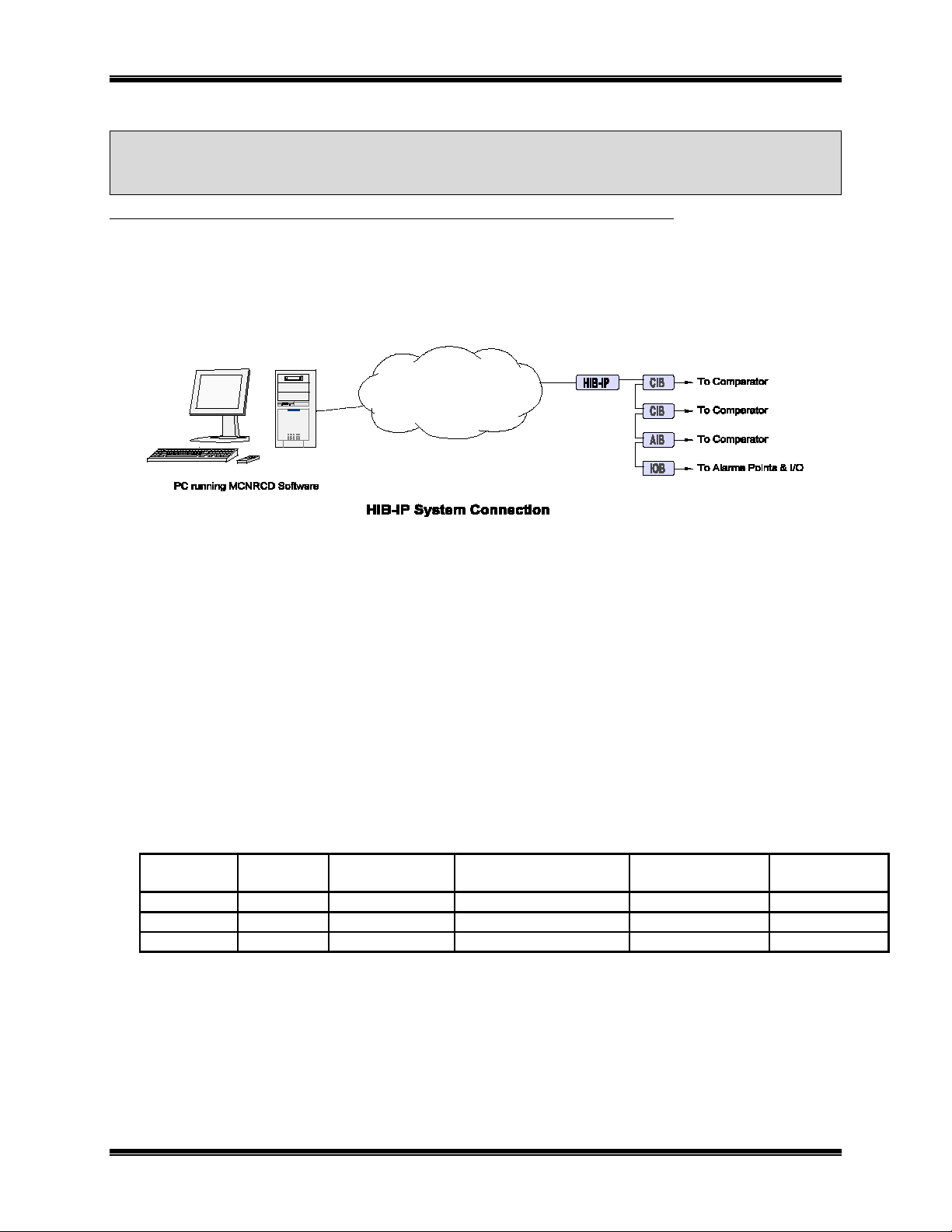
WHAT IS A HIB-IP?
The HIB-IP module is a remote network interface for an MCN (Monitorin g & Control Network) syste m. It is
used with the MCNRCD (MCN Remote Comparator Display) software in a PC. The HIB-IP connects to the
MCN network on one side and to a PC via an Ethernet connection.
Figure 1 MCN System with HIB-IP
Software compatibility:
MCNRCD (Windows) Version 2.00 & up Can connect to multiple HIB-IP units
MCN Server Version 2.00 & Up Can connect to multiple HIB-IP units
MCN Advanced Server Version 2.00 & Up Can connect to 4 HIB-IP units
(Can expand to 64 unite with ad ditional licenses.)
MCN Server 8000 Can connect to 1 HIB-IP Unit
(Can expand to 64 unite with ad ditional licenses.)
Available Models
The HIB-IP module is identified by the model number and version number found on the rear panel of the
module.
*AUI port not used for HIB-IP application.
HIB-IP 8000 vs. Legacy HIB-IP Units
The Legacy HIB-IP support s only the Legacy UDP Port.
The HIB-IP 8000 supports both the Legacy UDP Port and the HIB-IP 8000 UD P Po rt .
The HIB-IP 8000 UDP Port may be used in Motorola Solutions Inc. (MSI) Astro25™ Radio Network
Infrastructure (RNI) Version 7.13 and up.
In this manual, "HIB -IP" may be used in general to refer to either the HIB-IP Legacy or HIB-IP 8000 version
1. Introduction 5
Page 6

CTI Products, Inc. HIB-IP & HIB-IP 8000 Hardware Reference Manual
Part Number
Document
S2-60425
Monitoring and Control Network Comparator Display System Manual
S2-60426
CIB Comparator Interface Manual
S2-61043
MCNRCD for Windows Manual
S2-61170
MCN Server Software Manual
DDN1290
(S2-61600)
MCN Server 8000 Software Manual
HIB-IP versus EXB-IP
The HIB-IP is housed in a module similar to the EXB-IP. Although both connect to an MCN network and an
Ethernet network, there are some differences:
• EXB-IP modules are used in pairs to link distant MCN networks together over IP.
HIB-IP modules are used to connect a PC to a remote MCN Network over IP.
• The PC requires an MCN Network Interface to connect to the MCN Network.
If EXBs are used, the PC still needs an MCN network interface (such as a PCLTA , HIB-IP or
HIB-232 to connect to the MCN network.
• Multiple PCs (each with its own MCN Net work Interface) can connect to a local network served by
EXBs.
Only one PC can connect to a HIB-IP unit at a time.
HIB-IP 8000 Software Support
Use of the H IB-IP 8000 UDP port requires MCN software Version 6.10 or above.
Use of the HIB-IP 8000 units on a MSI RNI requires MCN Server 8000 Version 6.10 or higher.
REFERENCE DOCUMENTS
The following additional information is available.
1. Introduction 6
Page 7
CTI Products, Inc. HIB-IP & HIB-IP 8000 Hardware Reference Manual
123
45987
6
ERR
ACT
PWR
RESET
WINK
ETH RX
ETH TX
CSVC
RSVC
NETWORK
OUT
IN
ASYNC
NETWORK
NCB
NETWORK COMBINER
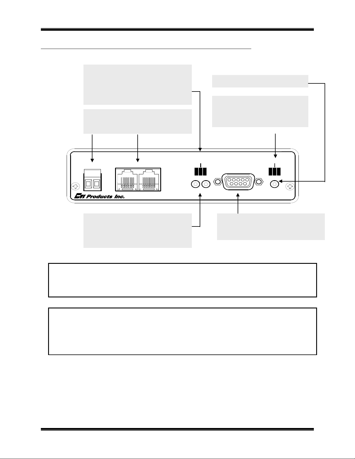
ETH TX LED Indicates when a packet has been
MCN NETWORK Connections
*** See MCN Network Notes 1 & 2***
Async Serial Programming Connector
RESET Button
Buttons for use with Custom
PWR LED Indicates correct input power
connected to the HIB-IP.
FRONT PANEL
WINK LED Normally not used.
ETH RX LED Indicates when a packet has been
RJ-45 Normal Network connection.
transmitted on the Ethernet port
May be winked during Custom
Configuration to identify a unit.
ERR LED Indicates an error condition
(see below and Appendix D)
ACT LED Indicates that a PC has
Screw Terminals not normally used.
Configuration
Press only when requested.
CSVC Button Identifies Control Processor
RSVC Button Not used
Used with PC running MCNConfig
to access IP address parameters
Figure 2 HIB-IP Front Pane
MCN Network Note 1
Unlike most other MCN modules, the HIB-IP does not inject power into the Network Out connector. It also
does not use any DC power from the Network In connector. All 8 pins on the Network In & Out connectors are
paralleled, so that any power from other modules will be passed through.
MCN Network Note 2
Although the MCN Network connectors are RJ-45s, THEY ARE NOT ETHERNET CONNECTORS. Because
the MCN network connectors on the front of the units may have DC power on them from other MCN devices,
DO NOT CONNECT THE NETWORK IN OR OUT CONNECTORS TO ETHERNET PORTS. THIS CAN
DAMAGE THE ETHERNET DEVICE. The Ethernet cable should be connected to the 10BASE-T connector on
the rear of the HIB-IP unit.
Front Panel Indicators – Additional Information
ETH RX LED (Yellow) – Indicates when a packet has been detected on the Ethernet port. NOTE: Flashing of
this LED does NOT necessarily mean that a packet addressed to this HIB-IP module has been received, just that
a packet has been detected on the Ethernet network.
ERR LED (Red) – Indicates a possible error condition. See Table E2 in Appendix E for a list of Error Code
definitions.
1. Introduction 7
Page 8

CTI Products, Inc. HIB-IP & HIB-IP 8000 Hardware Reference Manual
DC IN
OPTION
10BASE-T
1 2 3 4 5 6 7 8
ON
1 2 3 4 5 6 7 8
ON
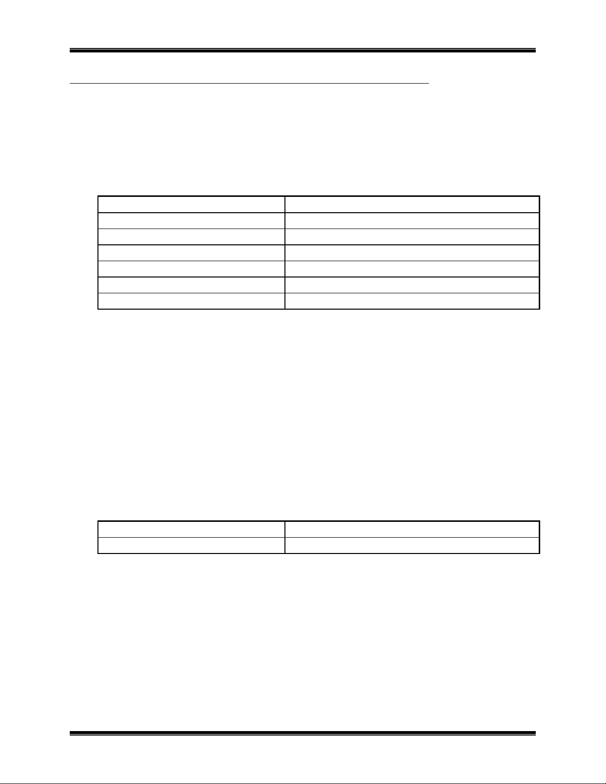
Function Up Down Default
1. Must be Up
Up
2. HTTP Enable HTTP On HTTP Page Off Down
3. Must be Down Down
4. Must be Up
Up
5. Must be Up Up
6. Must be Up Up
7. Must be Up............................................. Up
8. Must be Up
........................................
Up
DC IN Input Power
OPTION Switches
See t abl e below for options.
Ethernet Connector
*** See 10Base-T Warning ***
REAR PANEL
This powers only this unit.
Power is not passed to the
Network Out connector.
10Base-T)
Figure 3 HIB-IP Rear Panel
10Base-T Warning
Do not connect the 10Base-T connector to an MCN Network connector.
Damage could result.
Option Switch Settings
Figure 4 Option Switch Settings
1. Introduction 8
Page 9

CTI Products, Inc. HIB-IP & HIB-IP 8000 Hardware Reference Manual
HTTP Page Security Note
The HIB-IP and HIB-IP 8000 units have an HTTP page that shows the status of the unit, includi ng the IP
parameters programmed into i t a nd its On-Line / Off-Line status . This is useful for system troubleshooting.
This feature is turned off at the factory by default for HIB-IP 8000 units.
If you r network security policies allow you to use HTTP pages and you desire to have the HTTP page turned on
for troubleshooting, set Switch 2 U p and reset the unit.
If your network security policies mandate against this type of data being accessible through HTTP pages, verify
that the HTTP page by setting Switch 2 Down and resetting the unit. For f urther security, restrict physical
access to the unit and the networks to which it connects.
Note: Some networks (including Motorola So lutions, Inc. Radio Ne twork Infrastructure - RNI) have routers
and or firewalls that restrict HTT P traffic between certain network segment s . If you have such a syst em, you
may not be able to open the HTTP page from a different IP subnet, even if you have the HTTP page enabled on
the HIB-IP unit .
1. Introduction 9
Page 10

CTI Products, Inc. HIB-IP & HIB-IP 8000 Hardware Reference Manual
2. IP ADDRESS CONFIGURATION
This section describes the IP address parameters that must be set for the HIB-IP unit.
NOTE: DO NOT connect the HIB-IP module to a live IP network until it has been
reconfigured with new IP addresses. Network-wide problems could arise from connecting
devices to a network without coordination of addressing information. For usage with
dedicated fiber segments, see the note below.
Each system is different. Refer to the documentation for your system for the proper IP addr esses, sub nets, a nd
gateways t hat are assigned in your system.
MCN CONFIG SOFTWARE
The IP address parameters for the HIB-IP unit are downloaded into the units using the MCNConfig software
that comes with the MCNRCD or MCN Server software. The IP parameters are loaded into the unit through the
front panel serial programming connector. When used in this manual, MCN Config refers to the version
shipped with the MCN software and cold be:
Software MCN Config
MCNRCD MCN Config. exe
MCN Server MCN Config Server.exe
MCN Advanced Server MCN Config Server.exe
MCN Server 8000 MCN Config Server.exe
The MCN Config software will keep track of all HIB-IP units for a particular system. If you are running the
standard MCNRCD or MCN Server software, you will be able to use (1) HIB-IP. If you are running the
MCNRCD Advanced Server or MCN Server 8000 software, you may be able to access multiple HIB-IP units,
depending up on yo ur lice nse .
The MCNConfig program maintains a list of:
• Addressing parameters for all HIB-IP units in the system (inc luding the MCN Group & Module)
• Authorize d PC List
Each HIB-IP unit will be configured with:
• Its own HIB-IP addressing information
• Authorized PC information
• UDP Port
Fixed for Legacy HIB-IP versi ons 399 and below
Configurable for HIB-IP 8000 units (Version 400 & up):
Choice of: HIB-IP (Legacy) or HIB-IP 8000*
* HIG-IP 8000 UDP Port requires MCN Software 6.10 or higher.
Appendix F of this manual provide s an overview of IP addre s sing concepts.
2. IP Address Configuration 10
Page 11
CTI Products, Inc. HIB-IP & HIB-IP 8000 Hardware Reference Manual
IP SETTINGS WORKSHEET
Gather the following IP information for the system. IP information must b e obtained for each HIB-IP module
to be used (from the network administrator responsible for the IP network to which the HIB-IP module will be
attached):
Individual HIB-IP Parameters:
For each HIB-IP in the system, gather the following information:
HIB-IP Number
Name
HIB-IP Address (Host IP Address)
Subnet Mask
Gateway IP Address
MCN Group (00-FE)
MCN Module Number (00-7F)
Note: the Subnet Mask cannot be less restrictive than the following standard IP Class Subnet Masks
Class First Octet Standard Subnet Size Standard Subnet Mask
A 1-127 16,777,214 255.0.0.0
B 128-191 65,543 255.255.0.0
C 192-223 253 255.255.255.0
D 224-239 Multicast – Do not use.
E 240-255 Experimental – Do not use.
The HIB-IP units can accept a subnet mask that is more restrictive (more 1's set in the Subnet Mask), but not
less restrictive.
The Gateway address is the address of the router used to communicate with PCs in other subnets. The Gateway
subnet must be the same as the HIB-IP unit's subnet. If it is set to Empty, the HIB-IP will not be able to
communicate to PCs outside of its subnet.
_____._____._____._____
_____._____._____._____ or ____ Use Global
_____._____._____._____
Authorized PCs:
For each PC in the system that will connect to the HIB-IP, collect the following information:
PC Name
PC IP Address (Host IP Address)
See the MCN series Software manual for instructions on:
• Entering this data into the co nfiguration files using MCN Config series of software
• Downloading the configuration da ta into the HIB-IP units.
The configuration is downloaded from the PC to the HIB-IP unit using an 89-11314 Null-Modem serial cable
(9-pin female to 9-pin female.).
2. IP Address Configuration 11
_____._____._____._____
Page 12

CTI Products, Inc. HIB-IP & HIB-IP 8000 Hardware Reference Manual
BACKUP & RESTORE PROCEDURES
The HIB-IP units are not part of any automatic Back-up And Rest ore (BAR) system.
The HIB-IP configuration information is save d in the configuration fi l es generat ed by the MC N Config
software. It is recommended that you back up those files as part of your standard backup procedures.
See the appropriate MCN Software Manual for your system for additional Backup & Restore information.
SECURITY AND INFORMATION ASSURANCE RECOMMENDATIONS
Review these recommendatio ns be for e installation and follow them during installation and operation:
1. Software Installation Locations
Install the MCN Server 8000 software in default program directory recommended by Installshield.
2. Configure the MCN Server 8000 as described in the MCN Server 8000 manual.
3. Use the HIB-IP 8000 UDP ports for MSI RNIs as described in this manual.
4. For all software, network and device configuration, additionally take into consideration commercially
accepted practices, industry standards and the standards for your organization.
5. Do not save user files or system configura t ion files in the progr am directory.
6. Save system configuration files to a directory that requires Administrator rights so that u sers cannot delete
or edit the configuration files.
7. Always run the configuration software with the lowest permission set possible.
Note: The MCN Config Server so ft ware must be run with Administrator rig hts.
8. When configuring a system, do not enter Sensitive or Confidential information into the system
configuration files.
9. The configuration files generated by MCN Config Server software are not backed up as part of the
ASTRO® 25 Back UP & Restore (BAR) solution. Follow the Backup & Recovery procedures as listed in
the MCN Server 8000 manual.
10. Follow the applicable Backup & Recovery procedures for your system, PCs, and operating systems as
defined by your organization, the hardware and software vendors, and commercially acceptable practices.
11. Limit access to PCs, IP networks and MCN networks, both physically and through appropriate restrictions
in routers and switches
12. Use strong passwords where applicable.
13. Follow Motorola's and your organization's recommendations on security and Information Assurance.
14. Use the appropriate Windows Hardening Kits for PCs in your system.
15. Use anti-virus and anti-malware packages on P C s in your system.
16. Install appropriate security patches for installed software and operating system on PCs in your system.
17. Use of multiple NIC cards (Dual-Home systems) is not approved by MSI in ASTRO® 25 RNIs due to
Information Assurance (IA) sec urity concerns.
2. IP Address Configuration 12
Page 13

CTI Products, Inc. HIB-IP & HIB-IP 8000 Hardware Reference Manual
1 2 3 4 5 6 7 8
ON
Function Up Down Default
1. Must be Up
Up
2. HTTP Enable HTTP On
HTTP Page Off Down
3. Must be Down Down
4. Must be Up
Up
5. Must be Up Up
6. Must be Up Up
7. Must be Up
.............................................
Up
8. Must be Up
........................................
Up
3. INSTALLATION
PHYSICALLY INSTALL HIB-IP UNIT ONTO THE IP NETWORK
A) Set Option Switches:
• Set up t he OPTION switches for the desired operation.
The default settings should be suitable for most applications.
Less restrictive security:
Some system policies require that the HTTP page be turned off. For systems that allow the HTTP
page to be displayed for diagnostic purposes s, you may set Switch 2 Down to disab le the HT TP status
page.
B) Mount the HIB-IP units (See Appendix B for Mounting Option details):
Desk, Wall, or Rack Mounting
• Non-slip rubber feet are included on all HIB-IP modules to allow them to conveniently rest on any
horizontal surface. Four 6-32 threaded holes are also available on the bottom of the module to
allow bolting of the mod ule in an y convenient orientatio n. WARNIN G: Care should be taken to
limit protrusion of t he screw into the module to no more t han 0.125 inch from the module
bottom surface!
• Mounti ng kits are a vailable as options to allo w wall or rack (19” EIA) mounting of the HIB-IP
modules.
C) Make electrical connections (See Appendix C for connector details):
Grounding
• When wall or rack mounting the HIB, a suitable safety and protective earth ground should be
provided to the metal enclosure. The protective earth ground provides a path to ground for
electrostatic discharge (ESD) energy. This connection is most conveniently made directly to the
wall mount bracket or rack plate.
3 Installation 13
Page 14

CTI Products, Inc. HIB-IP & HIB-IP 8000 Hardware Reference Manual
DC IN
1 2 3 4
5
9876
ASYNC
DC Power Connection
DC power must be attached to the HIB-IP module via the DC IN
connector. A wall plug-in style power supply designed for the HIB-IP
module is an ava ila ble option.
C) Program IP Parameters:
The IP parameters are downloaded from the PC to the HIB-IP unit using a serial cable.
1. Be sure all the HIB-IP and Authorized PC parameters have been entered into the PC configuration files
using MCN Config series software as described in Section: 2. IP Address Configuration.
2. IP traffic can interrupt programming or viewing the data on a HIB-IP unit.
Remove IP traffic by disconnecting the Ethernet cable from the 10Base-T port on the rear of t he HIBIP unit.
3. Connect a Null Modem cable (CTI # 89-11314) between the PC and the Async
Serial Programming connector o n the HIB-IP.
Use of different cables may result in inconsistent or improper programming and
viewing of HIB-IP data.
See Appendix D. HIB-IP Programming Cable Pinout 89-11314 on page 25 for the proper cable pinout.
4. Load the IP parameters to the HIB-IP using the MCNConfig program:
Go to the Network Interfaces window and select the proper HIB-IP unit.
Right-click on the HIB-IP unit and select "Load HIB" from the pop-up wi nd ow.
3 Installation 14
Page 15

CTI Products, Inc. HIB-IP & HIB-IP 8000 Hardware Reference Manual
10BASE-T
AUI
NETWORK
OUT
IN
NETWORK
-
Select the proper COM port and hit "Program".
D) Connect t o the MCN & IP networks:
MCN Network Connection
• The local MCN network must be attached to the HIB-IP mo dule via the “NETWORK” connector
following standard guidelines as to cable type, cable length, and termination appropriate for the
selected transceiver.
The dual RJ45 NETWORK connector allows a daisy-chained network
connection method, as the network pins of the two RJ45 connectors are
directly paralleled. The HIB-IP unit does not inject DC power on the
network cable. It does not use any DC power from the cable.
The 2 pin removable terminal strip is wired in parallel with the network
connectio ns on the dual RJ45 connector. This co nnector is normally not
used.
Ethernet Connection
• The Ethernet network must be attached to the HIB-IP modul e via the Ethernet 10Base-T connector
on the rear of the unit.
WARNING: DO NOT connect the HIB-IP module to a live Ethernet network until it has been
reconfigured with its IP parameters. Network-wide problems could arise from connecting
devices to a network without coordination of addressing information.
The 10BaseT port utilizes a standard RJ45 connector. Level 5 unshielded
twisted pair cable should be used between the HIB-IP module and the IP
switch or hub. The length of this cable shoul d be less than 100 meters (328
feet).
An AUI connector was present on early units,
This connect or has bee n removed on later versions.
It was not used for HIB-IP applications.
3 Installation 15
Page 16

CTI Products, Inc. HIB-IP & HIB-IP 8000 Hardware Reference Manual
IP Switch Manual Settings Note
Some IP Switches (Like some HP Switches) that have Auto Speed and Duplex negation may not be
able to auto-negotia t e with the HIB-IP unit. In those cases, we recommend that you manually
configure the Ethernet port in the IP switch that connects to the HIB-IP. See the IP Switch
Configuration – Speed & HDX/FDX Negotiation section on page 31 for more details.
E. Run the MCNRCD program or t h e MCN Server program:
The installation of the HIB-IP units is now complete.
3 Installation 16
Page 17

CTI Products, Inc. HIB-IP & HIB-IP 8000 Hardware Reference Manual
4. TESTING
HTTP STATUS PAGE
The HIB-IP and HIB-IP 8000 units have an HTTP page that shows the status of the unit, including the IP
parameters programmed into i t a nd its On-Line / Off-Line status . This is useful for system troubleshooting. .
On the HIB-IP 8000 units, this feature is turned off at the factory by default.
Connect your PC to the HIB-IP via a LAN and enter the IP address of the HIB-IP in the address window:
Option Switch 2 must be Up for this page to be active.
The HTTP Status Page lists the current configuration for the HIB-IP unit.
Obviously, if the HIB-IP unit's own IP parameters are set wrong, you won't be able to see the Status Page.
Note: Some networks (including Motorola Solutions, Inc. Radio Network Infrastructure - RNI) have routers
and/or firewalls that rest rict H TTP traf fic bet ween certa in network se gme nts or subne ts. If y ou have suc h a
system, you may not be able to open the HTTP page from a different IP segment or subnet, even if you have
the HTTP page enabled on the HIB-IP unit.
Data entered from MCN Config program
(except for MAC Address)
On-Line Status indicator:
False: No PC Connected
True P C running MCN Software is connected
to HIB-IP unit.
Appendix A. Factory Default Settings 17
Page 18

CTI Products, Inc. HIB-IP & HIB-IP 8000 Hardware Reference Manual
Additional System Security & HTTP Page
If your network sec ur ity policies mandate against this type of data being accessible through HTTP pages, verify
that the HTTP page by setting Switch 2 Down and resetting the unit. For f urther security, restrict physical
access to the unit and the networks to which it connects.
If your network security policies allow you to use HTTP pages and you desire to have the HTTP page turned on
for troubleshooting, set Switch 2 U p and reset the unit.
Security Notes:
1. You can disable t he Status Page by setting Option Switch 2 Down.
(Remember to reset the unit after changing switch settings.)
2. The Authorized PCs restricts the use of MCNRCD or MCN Server PCs.
It does not restrict Pings or the ability to access the HTTP page.
3. You can further restrict the HIB-IPs ability to talk to units outside its own subnet by setting its Gateway
address to "0.0.0.0". For this case, the status page will display “EMPTY” for the Gateway address as
shown above.
PINGING THE HIB-IP UNIT
The “Ping” f unction ca n be run fro m the PC as a diagnostic tool to determine if a particular IP address can be
“seen” by a PC a nd the network infrastructure is configured to pass ICMP P ing messages and responses. The
HIB-IP will respond to IGMP Ping me ssa ge s fr o m the IP network.
Note: Some networks are configured to block the ICMP Ping messages and/or responses between certain
network segm ents of subne ts. The Ping func tion will not wo rk if the ICMP P ing messag es or responses are
blocked by the network.
Appendix A. Factory Default Settings 18
Page 19

CTI Products, Inc. HIB-IP & HIB-IP 8000 Hardware Reference Manual
APPENDIX
APPENDIX A. FACTORY DEFAULT CONFIGURATION
Control Processor
Restoring Factory Default Communication Parameters
If the Control Processor communication parameters are overwritten so that the HIB-IP cannot communicate
with the MCN Network, they can be restored as follows:
• Press the “RESET” button on the front of the HIB-IP unit
• After the “ERR” LED goes off, press the “RESET” button a second time.
The Control Processor communication parameters are now restored to factory defaults.
IP Address Parameters
The units are factory programmed as follows:
• IP Address: 192.1.1.1
• IP Address Mode: Unicast
• Subnet Mask: 255.255.255.0
• PC IP Address 192.1.1.201
Appendix A. Factory Default Settings 19
Page 20

CTI Products, Inc. HIB-IP & HIB-IP 8000 Hardware Reference Manual
CA-80374-100
FACEPLATE
SPACER
1 2 3 4
5
9876
ERR
ACT
PWR
RESET
WINK
ETH RX
ETH TX
CSVC
RSVC
NETWORK
OUT
IN
ASYNC
NETWORK
NCB
NETWORK COMBINER
APPENDIX B. MOUNTING OPTIONS
Wall mount and EIA 19” rack mount kits are available as options for the HIB-IP units from CTI Products, Inc.
The wall mount kit includes bra ckets to allow a single HIB-IP module to be mounted to any flat surface. The
rack mount kit includes an adapter allowing up to three HIB-IP modules to be mounted i n a single rack unit
height.
Rack Mount Option
The rack mount option allows up to three HIB-IP modules to be mounted in a one rack unit height (1.75 inches)
of a standard 19 inch rack. The modules are mounted in the rack plate by removing its’ front bezel and
remounting t he module into the rack plate. Figure 5 shows an explod ed view of the ra ck mount instal lation.
The top diagram shows the front view of the bracket with one module installed. The bottom two diagrams show
a side view of the module installation into the rack adapter and rack adapter installation into the rack,
respectively.
Figure 5 HIB-IP Module Rack Mounting
Appendix B. Mounting Options 20
Page 21

CTI Products, Inc. HIB-IP & HIB-IP 8000 Hardware Reference Manual
Step
Operation
1
Remove the front panel from the module, including the bezel, by removing the two
module.
2
Position the module behind the rack adapter, lining up the holes in the rack adapter with
the front panel screw holes on the module.
3
Position the front panel in front of the rack ada pter, lining up the front panel with the
module.
4
Fasten the front panel and module to the rack adapter with the Philips head screws that
were previously removed.
5
Position the rack adapter into your rack, lining up the four mounting holes of the rack
adapter wit h mounting holes in the ra ck frame.
6
Position the two spacers in the front of the rack adapter, aligning the cutouts in the
spacers with the holes of the adapter.
7
Install mounting screws (customer provided) into the rack.
Step
Operation
1
From the front of the module, slide the PC board out of the housing.
2
Remove the back panel of the module.
3
Attach either bezel and front panel or rack kit and front panel to the housing with two
Philips head screws.
3
From the rear of the module, slide the PC board back into the housing (there are
first).
4
Attach bezel and rear panel to the housing with two Philips head screws.
To attach a module to the rack adapter, and then mount the rack adapter into the rack, follow the steps below.
WARNING
Do not allow the PC board to slide out of the housing when the front panel is removed. If it does,
DO NOT slide the PC board back into the housing from the front of the module. Doing so may
damage the unit, causi ng the unit to malfunction when powered on. D oing so will void the unit’s
warranty. Re turn the PC board to t he housing b y sliding it only from the re ar. (See instructions
below.)
Rack Mounting Instructions
Philips head screws in the faceplate. The bezel is not used when rack mounting the
When the module’s front panel is removed, do not allow the PC board to slide out of the housing. If the PC
board does slide out of the housing, you must follow the steps below to replace the PC board in the housing.
DO NOT RE-INSTALL THE PC BOARD FROM THE FRONT OF THE HOUSING !
Re-Installing a PC Boa r d i n its housing
markings on the PC board to indicate which edge to insert i nto the rear of the housing
Appendix B. Mounting Options 21
Page 22

CTI Products, Inc. HIB-IP & HIB-IP 8000 Hardware Reference Manual
Industry
Canada
NOTE:
THE NUMBERS ON THIS DRAWING REFER TO THE ITEM NUMBERS
ON THE CORRESPONDING BILLS OF MATERIAL FOR THIS ASSEMBLY.
24 VDC
100 mA
BOTTOM VIEW
USE ONLY 6-32 X 1/4" LONG
FLAT HEAD SCREWS TO ATTACH THE
WALL MOUNT BRACKET TO THIS UNIT.
TO PREVENT DAMAGE TO THE CIRCUIT BOARD.
CAUTION!
USE ONLY 6-32 X 1/4" LONG
FLAT HEAD SCREWS TO ATTACH THE
WALL MOUNT BRACKET TO THIS UNIT.
TO PREVENT DAMAGE TO THE CIRCUIT BOARD.
CAUTION!
ETL APPRO
3.500
1.980
6.130
6.700
1.642
TOP VIEW
1
2
Provided by installer.
Allow room on ends
for connectors.
Allow room on ends
for connectors.
SIDE VIEW
1.980
QTY 2
QTY 4
QTY 4 NO. 8 SCREWS OR OTHER
APPROPRIATE HARDWARE.
OR
OR
1
2
3
4
5
6
7
8
ON
OPTION A
DC IN
ERR
ACT
PWR
RSVC
CSVC
AUDIO
LINE
CD
OH
RESET
CMD
NCB
NETWORK COMBINER
NETWORK
Wall Mount Option
The wall mount option allows an HIB-IP module to be mounted to any flat surface. The HIB-IP module has
four screw holes on the bottom. Simply attach the two mounting plates to the bottom of the module using the
four flat-hea d scre ws pro vided wit h the wall mount kit. This assemb ly is the n attached to the flat surface with
user-provided fasteners. Figure 6 shows a dimensioned view of the wall mount installation.
Be sure to use the flat head screws provided with the wall mount kit. If you are not using the wall mount
kit from CTI Products, Inc., make sure that the screws do not protrude into the enclosure more than 0.12 5
inches fro m t he bottom surface of the module.
Using a longer screw that touches the PC board insid e the module may damage the module. Doing so will
void the unit’s warranty.
Appendix B. Mounting Options 22
Figure 6 HIB-IP Module Wall Mounting
CAUTION
Page 23

CTI Products, Inc. HIB-IP & HIB-IP 8000 Hardware Reference Manual
Pin
Function
Notes
1
Network
Network co nnection is NOT polarity sensitive
2
Network
Pins 1,2 of IN and OUT connectors tied parallel
3
No Connection
Note 1
Pin 3 of IN and OUT connectors tied together
4
No Connection
Pin 4 of IN and OUT connectors tied together
5
No Connection
Pin 5 of IN and OUT connectors tied together
6
No Connection
Note 2
Pin 6 of IN and OUT connectors tied together
7
No Connection
Note 2
Pin 7 of IN and OUT connectors tied together
8
No Connection
Note 1
Pin 8 of IN and OUT connectors tied together
Pin
Function
1
Network
2
Network
+
-
Polarity
DC IN
Front View
NETWORK
OUT
IN
1
2
345
6
7
8
NETWORK
1
2
APPENDIX C. CONNECTOR DETAILS
DC IN Connector
Connector type: 2.5 x 5.5 mm coaxial
Mating Connector: Switchcraft 760 or equivalent
Connector pinout: CT I Pro d ucts, Inc. standard power
supply is wired with center pin positive,
HIB-IP module can accept either pin
positive, polarity routing is provided
internal.
NETWORK Connectors
RJ45 Connectors:
Pins 1 and 2 of both RJ45 connectors as well as the screw-terminal connector
are all wired in parallel.
Connector Type: Standard RJ45 telephone connector, 8 position 8
contact.
Note 1: May have + DC power on this pin from other MCN modules.
Note 2: May have - DC power on this pin fro m other MCN modules.
2-Position Screw-Terminal:
Mating Connector: Weidmueller 128176
Appendix C. Connector Details 23
Page 24

CTI Products, Inc. HIB-IP & HIB-IP 8000 Hardware Reference Manual
Note: in
Function
1
Ethernet TX
2
Ethernet TX
3
Ethernet RX
4
N/C 5 N/C
6
Ethernet RX
7
N/C 8 N/C
Pin
Function
1
Data Carrier Detect
2
RX 3 TX
4
Data Terminal Ready
5
Signal Ground
6
Data Set Ready
7
Clear to Send
8
Request to Send
9
N/C
Pin
Function
1
Chassis Ground
2
Collision
3
Ethernet TX
4
Chassis Ground
5
Ethernet RX
6
Signal Ground
7
N/C 8 N/C
9
Collision
10
Ethernet TX
11
Chassis Ground
12
Ethernet RX
13
+12V
14
Chassis Ground
15
N/C
Ethernet Connectors
10BaseT Connector: AUI Connector (early versions)
Note: This connector removed on later versions
Connector type: Standard RJ45 female. Connector type: Standard D-Subminiature 15 pin
female.
ASYNC Serial Programming Connector
When this port is connected to a PCs serial port, the MCNConfig program can be used to configure the IP
address parameters.
Connector type: Standard D-Subminiature 9 pin male. DTE (Like I BM PC 9 pin)
Null Modem cable (CTI # 89-11314) required for connection to
PC.
Appendix C. Connector Details 24
Page 25

CTI Products, Inc. HIB-IP & HIB-IP 8000 Hardware Reference Manual
Pin
Function
Function
Pin
1
DCD
DCD
1 2 RXD
RXD
2 3 TXD
TXD
3 4 DTR
DTR
4
5
GND
GND
5 6 DSR
DSR
6
7
CTS
CTS
7
8
RTS
RTS
8
N/C N/C
9
APPENDIX D. HIB-IP PROGRAMMING CABLE PINOUT 89-11314
Data Carrier Detect
Data Terminal Ready
Signal Ground
Data Set Ready
Clear to Send
Request to Send
Data Carrier Detect
Data Terminal Ready
Signal Ground
Data Set Ready
Clear to Send
Request to Send
Programming Cable Warning
Always use the proper cable.
If an improper cable is used, the MCN Config so ftware might not be able to
consistently View or Upload the data to the HIB-IP unit.
Appendix D. HIB-IP Programming Cable 25
Page 26

CTI Products, Inc. HIB-IP & HIB-IP 8000 Hardware Reference Manual
If the PWR LED . . .
REASON
CORRECTIVE A CTION
unit is receiving proper DC input power.
power supply
at 10-32VDC.
power.
connector (10-32VDC).
If the ERR LED . . .
REASON
CORRECTIVE A CTION
condition was detected.
off.
pressed.
Flashes one time, & repeats
EE Read Fail
Return to CTI Products for repair
Flashes 2 times, & repeats
MAC Address Read Fail
Return to CTI Products for repair
Manual)
Manual)
Manual)
Manual)
Manual)
Switch 3 DOWN, then Reset the unit.
Is steadily illuminated.
Unit not functioning.
Return to CTI Products for repair
APPENDIX E. TROUBLESHOOTING
Table E1
Steadily illuminates Normal operation indicating that HIB-IP
Occasionally illuminates Loading of HIB-IB is excessive for the
Does not illuminate HIB-IP unit is not receiving DC input
Go to next Table.
Check that power suppl y can deliver 5 watts
Check for proper voltage at “DC IN”
Table E2
Does not illuminate Normal operation indicating no error
Occasionally flashes on, then
Flashes 3 times, & repeats Target not configured Configure IP parameters in MCN Config
Flashes 4 times, & repeats Host not configured Configure IP parameters in MCN Config
Normal operation when “CSVC” button is
Go to next Table.
Go to next Table.
Program, then “Load HIB” through
serial port.
(See Secti o n “2. IP Address Configuration” on
Page 10
, and see MCNRCD Software
Program, then “Load HIB” through
serial port.
(See Secti o n “2. IP Address Configuration” on
Page 10
, and see MCNRCD Software
Flashes 6 times, & repeats One of the following is set to 0:
Host IP Address
Host IP Mask
IP Mode
Flashes 7 times, & repeats No Authorized PC List Configure IP parameters in MCN Config
Flashes 8 times, & repeats Multicast IP Address Error: Multicast mode
is selected, but Multicast Address =
0.0.0.0
Flashes 10 times, & repeats Factory Test Mode: Option Switch 3 is UP Place in Operating Mode by placing Option
Configure IP parameters in MCN Config
Program, then “Load HIB” through
serial port.
(See Secti o n “2. IP Address Configuration” on
Page 10
, and see MCNRCD Software
Program, then “Load HIB” through
serial port.
(See Secti o n “2. IP Address Configuration” on
Page 10
, and see MCNRCD Software
Configure IP parameters in MCN Config
Program, then “Load HIB” through
serial port.
(See Secti o n “2. IP Address Configuration” on
Page 10
, and see MCNRCD Software
Appendix E. Troubleshooting 26
Page 27

CTI Products, Inc. HIB-IP & HIB-IP 8000 Hardware Reference Manual
If the ETH TX LED . . .
REASON
CORRECTIVE A CTION
Ethernet port.
HIP-IP
cabling.
If the ETH RX LED . . .
REASON
CORRECTIVE A CTION
network.
HIP-IP
cabling.
If the ACT LED . . .
REASON
CORRECTIVE A CTION
software is connected to the HIB-IP
(Reset unit after changing switch settings)
Web Page not available . .
REASON
CORRECTIVE A CTION
accessed
unit.
Table E3
Occasionally flashes on, then
off.
Never illuminates IP messages are b eing transmitted from the
Normal operation indicating a message
packet has been transmitt ed from the
Table E4
Occasionally flashes on, then
off.
Never illuminates IP messages are not being received by the
Normal operation indicating a message
packet has been detected on the IP
Table E5
Is steadily illuminated Normal operation indicating a PC
running MCNRCD or MCN Server
Never illuminates 1. PC not running MCNRCD or MCN
Server Software
2. PC not configured to access HIB-IP
3. No IP connection between PC & HIBIP
4 HIB-IP IP parameters wro ng or
PC not in Authorized PC list.
5. Ethernet port not enabled
Go to next Table.
Check the integrity of the IP network and
Go to next Table.
Check the integrity of the IP network and
None.
1. Start the software
2. Use MCNConfig to Re-configure PC to
access HIB-IP. Restart the MCNRCD or
MCN Server software.
3. Check IP cabling.
Try to P ing HIB-IP from PC
Check PCs IP address
Check ETH RX LED for activity
Check the Status Page
4. Re-load the IP p arameters & Authorized
PC list in the HIB-IP
5. Check Option Switch settings:
10BaseT (Default), 7 & 8 UP
AUI (Fiber), 7 & 8 DOWN
Table E6
If the Web page cannot be
To request RMA for return of product to CTI Products, call Customer Support at +1-513-595-5900
Appendix E. Troubleshooting 27
HTTP option is disabled Place Option Switch 2 UP, then Reset the
Page 28

CTI Products, Inc. HIB-IP & HIB-IP 8000 Hardware Reference Manual
APPENDIX F. SPECIFICATIONS
HIB-IP
DC Power Input: 10 to 32 VDC, unregulated (10BaseT)
15 to 32 VD C unregulated (AUI - Fiber)
5 watts maximu m
Size: 7.5” D x 5.6” W x 1.6” H
Operating Temperature: 0 to 60 °C
Humidity: 10-95% non-condensing
Mounting: Desktop with integral non-slip feet
Wall mount or 19” rack mount with optional adapters
Configuration:
Ethernet IP Parameters Using MCN Config progra m supplied with MCNRCD software.
Transceivers Supported:
MCN 78K
Ethernet 10Base-T HDX
IP Addressing Modes: Unicast
IP Transport: UDP
Status Page HTTP (may be disabled)
UDP Ports: HIB-IP Legacy: Source 1283 (fixed)
Dest: 1100 dest. (fixed)
HIB-IP 8000: Source: 1283 (fixed)
Dest: "Legacy" (1100) or
"HIB-IP 8000" or
1-65,534 (User selectable).
"HIB-IP 8000" UDP Port for use with Motorola Solutions Inc. Astro25™
Radio Network Infrastructure (RNI) Version 7.13 and up
Operating System: Proprietary
(Non-Windows, Non-Linux, Non-Unix)
Appendix F. Specifications 28
Page 29

CTI Products, Inc. HIB-IP & HIB-IP 8000 Hardware Reference Manual
Class
(Beginning Bits)
Networks
(Ending Bits)
Subnets
Range
A 8 126
24
16.7 million
1-126 B 16
16,000
16
65,000
128-191 C 24
2 million
8
254
192-293
APPENDIX G. IP ADDRESSING
Conventions
Any node connected to an IP (Internet Protocol) network must be identi fi ed with a uni que 32-bi t address. These
32-bit addresses are commonly written in dotted decimal notation as four decimal numbers (referred to as octets
because each decimal number represents 8 bits) separated by decimal points. Each octet can be a number from
1 to 255. For example, 131.9.1.2 is a valid IP address. The IP address assigned to a network device is
commonly called the Host IP Address. By having unique addresses on a network, individual stations (also
called hosts or nodes) can be identified on the network.
IP Address Classes
There are five types of IP addresses. Three are associated with networks – Class A, B, and C.
• Class A addresses are for networks that have a large number of hosts, up to a maximum of 16,777,214
on a single IP network. The first octet is between 1 and 126. (127 is reserved for loopback and is used
for internal testing on the local machine.)
• Class B addresses are for medium-sized networks. The first octet is between 128 and 191.
• Class C addresses are for small networks, up to 255 hosts. The first octet is between 192 and 223.
• Class D addresses are reserved for multicasting and the first octet is between 224 and 239. These are
not used for Host (device) addresses.
• Class E addresses (240 to 255) are reserved and should not be used.
An IP address c onsists o f two p arts – one part identifies the network, and one part identifies the host (or node).
The NetID portio n of the IP address identifies the ph ysical network segment. The HostID portion of the IP
address identifies the node within the network segment. The following table lists the capacities of each IP
address and the bits used as NetID and HostID.
IP
Net ID
# of
Host ID
# of Hosts or
1st byte
Subnetting using Subnet Masks
A portion of the host bits can be used to “subnet the network”. T he subnet mask identifies the “NetID” and
“HostID” portions of the IP address in a bitwise fashion. The mask is constructed by placing a “1” in any bit
that is part of a subnetwork address. So subnet mask bits that are SET define the NetID, and CLEARED subnet
mask bits define the HostID.
A subnet mask of 255.255.255.0 defines the NetID as the first three octets, and the HostID as the last octet. For
example, for the address 192.47.73.111 and the subnet mask of 255.255.255.0, the subnetwork can be
identified as 192.47.73.0.
Summary of Important Networking Details
• A specific “NetID” can exist on only ONE port of ONE IP router.
• The “NetID” portion of the Host Address and the Gateway Address MUST BE THE SAME.
• If a functioning unit is moved to a different location, its Host IP Address and Default Gateway IP
Address MUST BE CHANGED to match the “NetID” at the new location.
Appendix G. IP Addressing 29
Page 30

CTI Products, Inc. HIB-IP & HIB-IP 8000 Hardware Reference Manual
Layer 3
Layer 2
Layer 1
IP Router
Bridge
Hub
EXB-IP Network Extender
Switch
Repeater
HIB-IP Unit
NIC
Concentrator
MAC Addresses
Whereas IP uses Logical Addresses to identify a host (node), other protocols use Hardware Addresses called
Media Access Control addresses, or MAC addresses. MAC addresses are set at the factory at time of
manufacture and cannot be changed. (IP addresses can be changed at any time.) A MAC address consists of
six octets, in hexadecimal notation, separated by colons. An example would be: 00:10:EE:00:02:34.
The first three octets in a MAC address identify the manufacturer. In the above example, 00:10:EE identifies
CTI Products as the manufacturer of this device. The last three octets are sequentially assigned by the
manufacturer to form a type of serial number. In this way, no two devices have the same MAC address.
Address Resolution Protocol (ARP)
Since IP uses Logical Addresses at the OSI Network Layer (Layer 3) and Ethernet uses MAC addresses at the
OSI Data Link Layer (Layer 2), Address Resolution Protocol is used whenever IP is used over the Ethernet.
ARP is needed to convert an IP address to a MAC address. T he client then stores this resolved address for a
period of time in its ARP cache. An ARP cache is a lookup table, typically in a router, that will store a quantity
of resolved addresses for devices that it must communicate with.
When a message is destined for an IP address whose MAC address has not yet been resolved, an ARP
REQUEST is sent from the local host as a broadcast message, asking for MAC identification. A remote host
with the IP address in question generates an ARP RESPONSE. This ARP RESPONSE contains the requested
MAC address. The local host receives the message, and places the IP Address and the matching MAC Address
in its ARP C ac he . T he or igi n a l mes sa ge is then sent usi ng t he MAC Address found previously. Any additional
messages to this remote IP address will be sent using the MAC address found in the local host’s ARP cache.
Ethernet 10BaseT Cables
When connecting two IP devices together, either a straight-through cable or a crossover cable may be required.
If interconnecting similar devices, then a crossover cable is needed. Examples would be interconnecting two
EXB-IP routers, or two IP routers, or two hubs, or two computers. Generally, if the two devices are both Layer
3 devices, then a crossover cable is required. Routers operate at Layer 3. Similarly, if the two devices are
Layer 1 or 2 devices, they would also require a crossover cable. Bridges, switches, and Network Interface
Cards (NIC) operate at Layer 2, and hubs, repeaters, and concentrators operate at Layer 1.
If interconnecting dissimilar devices, the n a straight-throu gh cable is needed. Dissimilar devices would involve
one Layer 3 device and a Layer 1 or Layer 2 device.
The following table summarizes device types in each layer.
Appendix G. IP Addressing 30
Page 31

CTI Products, Inc. HIB-IP & HIB-IP 8000 Hardware Reference Manual
Standard End
Standard End
Signal Name
Wire Color
Pin Pin
Wire Color
Signal Name
TD+
White/Orange
1
1
White/Orange
TD+
TD-
Orange
2
2
Orange
TD-
RD+
White/Green
3
3
White/Green
RD+
Not used
Blue
4
4
Blue
Not used
Not used
White/Blue
5
5
White/Blue
Not used
RD-
Green
6
6
Green
RD-
Not used
White/Brown
7
7
White/Brown
Not used
Not used
Brown
8
8
Brown
Not used
Standard End
Crossover End
Signal Name
Wire Color
Pin Pin
Wire Color
Signal Name
TD+
White/Orange
1
3
White/Green
RD+
TD-
Orange
2
6
Green
RD-
RD+
White/Green
3
1
White/Orange
TD+
Not used
Blue
4
5
Blue
Not used
Not used
White/Blue
5
4
White/Blue
Not used
RD-
Green
6
2
Orange
TD-
Not used
White/Brown
7
8
White/Brown
Not used
Not used
Brown
8
7
Brown
Not used
The following table lists the connections for a straight-through cable.
The following table lists the connections for a crossover cable.
Auto-MDIX
Note that some newer PCs and IP Switches feature "Auto-MDIX" Ethernet connectors. These Ethernet
connections will automatically sense the direction of the connection and do not require cross-over cables.
IP Switch Configuration – Speed & HDX/FDX Negotiation
Some IP Switches (like some HP Pro-Curve Switches) that have Auto Spe ed and Dupl ex negat ion may no t be
able to auto-negotiate with the HIB-IP unit. This may cause the HIB-IPs units (and their connected MCN
modules to cycle off-line and on-line in the MCN software.
In those cases, we recommend that you manually configure the Ethernet port in the IP switch that connects to
the HIB-IP.
Manual Con figuration:
Speed: 1 0 Mbits/sec
Duplex HDX
Appendix G. IP Addressing 31
Page 32

CTI Products, Inc. HIB-IP & HIB-IP 8000 Hardware Reference Manual
APPENDIX H. HIB-IP FIRMWARE NOTES
This manual describes products which include copyrighted CTI Products, Inc. computer programs in
semiconductor memory. CTI Products, Inc. re s erves all ri ghts for the s e programs, including the exclusive right
to copy or reproduce the copyrighted computer programs in any form. No copyrighted computer program
contained in products described in this manual may be copied, reproduced, decompiled, disassembled, or
reversed engineered in any manner without express written permission of CTI Products, Inc. The purchase of
products from CTI Products, Inc. shall not be deemed to grant either directly or by implication, estoppel, or
otherwise, any license under the copyrights, patents, or patent applications of CTI Products, Inc., except for the
normal non-exclusive, royalty fee license to use that arises by operation of law in the sale of the product.
Regents of the University of California License
Portions of the outbound Ping function in the firmware in the HIB-IP and HIB-IP 8000 units are used under
license from Regents of the University of California. The following disclosure is r e quired by that license and
applies only to portions of the Ping function.
The original license was modified as of July 22, 1999 to delete the requirement for acknowledgement wi thi n
advertising materials per notice from:
William Hoskins
Director, Office of Technology Licensing
Universit y of Califor ni a, Berkeley
as stated at:
ftp://ftp.cs.berkeley.edu/pub/4bsd/README.Impt.License.Change
and affirmed in 2012 at:
http://ipira.berkeley.edu/sites/default/files/shared/Advertising_clause_removed_from_BSD_license.pdf
The resultant license follows.
Copyright (c) 1987 Regents of the University of California. All rights reserved.
Redistribution and use in source and binary forms are permitted provided that the above copyright notice and
this paragraph are duplicated in all such forms and that any documentation and other materials related to such
distribution and use acknowledge that the software was developed by the University of California, Berkeley.
The name of the University may not be used to endorse or promote products derived from this software without
specific prior written permission. THIS SOFTWARE IS PROVIDED ``AS IS'' AND WITHOUT ANY
EXPRESS OR IMPLIED WARRANTIES, INCLUDING, WITHOUT LIMITATION, THE IMPLIED
WARRANTIES OF MERCHANTIBILITY AND FITNESS FOR A PARTICULAR PUR POSE.
Appendix H. HIB-IP Firmware Notes 32
Page 33

CTI Products, Inc. HIB-IP & HIB-IP 8000 Hardware Reference Manual
APPENDIX I. REGULATORY NOTES
Radio Frequency Emissions and Immunity
This equip ment generates, uses, and can radiate radio frequency energy and, if not installed and used in accordance with the instruction manual,
may cause harmful interference to radio communications. Operation of this equipment in a residential area is likely to cause harmful interference
in which case the user will be requ ired to correc t the interfer ence at his o wn expense. Changes or modifications to this unit not ex pressly
approved by the party responsible for compliance could void the user’s authority to operate the equipment. Limits specified in the standards listed
below are designed to provide reasonable protection against harmful interference when the equipment is operated in a commercial environment.
UNITED STATES: This equipment has been tested and found to comply with the limits for a Class A digital device, pursuant to Part 15 of the
FCC Rules.
CANADA: This Class A digital apparatus meets all requirem ents of the Can adian Interference-Causing Equipment Regulations.
Cet appareil numérique de la classe A res pecte tout es les exigenc es du Règlement sur le matériel brouilleu r du Canada.
EUROPE: This equipment has been tested and found to conform with the following standards: EN60950, EN50082-1, IEC801-2, IEC801-3,
IEC801-4, and EN55022. This equipment complies with the requirements of the following directives: Low Voltage Directive 73/23/EEC, EMC
Directive 89/336/EEC, and 93/68/EEC Harmonization of CE Marking
Appendix I. Regulatory Notes 33
Page 34

CTI Products, Inc. HIB-IP & HIB-IP 8000 Hardware Reference Manual
INDEX
A
ARP - Address Res olution Protocol .............................................28
AUI ..............................................................................................15
B
Badkup & Restore Procedu res ......................................................12
Broadcast......................................................................................28
C
Connector .....................................................................................21
Control Processor .........................................................................17
D
Dotted Decimal ............................................................................27
E
ERR LED ................................................................................. 7, 17
Ethernet connector........................................................................15
Ethernet Connector ................................................................... 8, 15
F
Factory Default Parameters ..........................................................17
Front Panel .....................................................................................7
G
Gateway Add re s s .........................................................................27
H
Hardware Address .............................................. See M AC Address
HostID ..........................................................................................27
I
Internet Protocol ...........................................................................27
IP Address ................................................................................... 28
IP Settings Worksheet .................................................................. 11
L
LEDs.............................................................................................. 7
Logical Address ....................................................... See IP Address
M
MAC Address .............................................................................. 28
Media Access Control ......................................... See MAC Address
Mounting Kit ............................................................................... 13
Multicast ...................................................................................... 27
N
NetID ........................................................................................... 27
NETWORK connector ................................................................. 15
O
Octets ........................................................................................... 27
P
Ping.............................................................................................. 16
Power Connection ........................................................................ 14
Programming Cable ..................................................................... 22
R
Rear Panel ...................................................................................... 8
RJ45 ....................................................................................... 15, 21
S
Serial Cable ................................................................................. 22
Specifications .............................................................................. 26
Subnet Mask ................................................................................ 27
Switch Settings .............................................................................. 8
Index 34
Page 35

Page 36

 Loading...