

Page 1

MCN Monitoring and Control Network
Comparator Display System
Host Computer Interface Module
HIB
Hardware Reference Manual
S2-60427-210
NOTE: This module must be configured before being installed in your system. Refer to section 4 and 7
for information about the module configuration.
68-10855-210
Page 2
FCC Statement
This equipment has been tested and found to comply with the limits for a Class A digital device, pursuant to Part 15 of the FCC Rules. These
limits are designed to provide reasonable protection against harmful interference when the equipment is operated in a commercial environment.
This equipment generates, uses, and can radiate radio frequency energy and, if not installed and used in accordance with the instruction manual,
may cause harmful interference to radio communications. Operation of this equipment in a residential area is likely to cause harmful
interference in which case the user will be required to correct the interference at his own expense.
Warning: Changes or modifications to this unit not expressly approved by the party responsible for compliance could void the user’s authority to
operate the equipment.
DOC Statement
This Class A digital apparatus meets all requirements of the Canadian Interference-Causing Equipment Regulations.
Cet appareil numérique de la classe A respecte toutes les exigences du Règlement sur le matériel brouilleur du Canada.
Computer Software Copyrights
This manual describes products which include copyrighted CTI Products, Inc. computer programs in semiconductor memory. CTI Products, Inc.
reserves all rights for these programs, including the exclusive right to copy or reproduce the copyrighted computer programs in any form. No
copyrighted computer program contained in products described in this manual may be copied, reproduced, decompiled, disassembled, or
reversed engineered in any manner without express written permission of CTI Products, Inc. The purchase of products from CTI Products, Inc.
shall not be deemed to grant either directly or by implication, estoppel, or otherwise, any license under the copyrights, patents, or patent
applications of CTI Products, Inc., except for the normal non-exclusive, royalty fee license to use that arises by operation of law in the sale of the
product.
Information contained in this document is subject to change without notice and does not represent a commitment on the part of CTI Products,
Inc.
No part of this manual may be reproduced or transmitted in any form or by any means, electronic or mechanical, including photocopying and
recording, for any purpose without the written permission of CTI Products, Inc.
Copyright 1995-2002, CTI Products, Inc. All rights reserved.
MCN is a trademark of CTI Products, Inc. Other trademarks referenced are properties of their respective owners.
Manual Revisions
Rev. Description
205 Covers Rev 200 of HIB Module
210 Added Windows NT, 2000, XP information, FixMouse for Win 2K,
Rev 250 of HIB hardware
CTI Products, Inc.
1211 W. Sharon Rd.
Cincinnati, OH 45240
If you have questions about the MCN comparator display system, call us at:
(513) 595-5900. (8:30 to 5:00 Eastern)
68-10855-210
Page 3

HIB Hardware Reference
CTI Products, Inc.
1. INTRODUCTION ..................................................................................................................1
1.1 R
EFERENCE DOCUMENTS
.................................................................................................... 1
2. THEORY OF OPERATION ................................................................................................. 2
3. SPECIFICATIONS ................................................................................................................3
4. OPTION SWITCHES ............................................................................................................ 4
5. CONNECTORS...................................................................................................................... 6
6. MOUNTING ........................................................................................................................... 8
7. DEVICE DRIVER INSTALLATION .................................................................................. 9
7.1 CTIHIB.SYS V
7.2 C
7.3 D
OMMAND LINE EXAMPLES FOR
EVICE DRIVER TESTING
ERSIONS
................................................................................................... 10
CTIHIB.SYS................................................................. 11
.................................................................................................. 11
8. PC MODEM SUPPORT...................................................................................................... 12
8.1 DOS.................................................................................................................................. 12
8.2 W
8.3 W
INDOWS
INDOWS
95 & 98 ........................................................................................................... 12
NT, 2000, & XP.............................................................................................. 12
9. FIXMOUSE FOR WINDOWS 2000................................................................................... 12
10. HIB MODEM SUPPORT................................................................................................. 13
11. TROUBLESHOOTING ................................................................................................... 14
68-10855-210
i
Page 4

HIB Hardware Reference
CTI Products, Inc.
Standard Limited Hardware Warranty
LIMITED WARRANTY.
for a period of ONE (1) YEAR from date of shipment to original purchaser. Under this warranty, our obligation is limited to repairing or
replacing any equipment proved to be defective by our inspection within one year of sale to the original purchaser. This warranty shall not apply
to equipment which has been repaired outside our plant in any way, so as to, in the judgment of CTI Products, Inc. affect its stability or
reliability, nor which has been operated in a manner exceeding its specifications, nor which has been altered, defaced, or damaged by lightning.
Equipment manufactured by CTI Products, Inc. is warranted to be free from defects in material and workmanship
CUSTOMER REMEDIES
period shown, the customer shall call CTI Products, Inc. to obtain a Return Authorization Number and return the product or module, shipping
and insurance prepaid. CTI Products, Inc., will then at its option, either repair or replace the product or module and return it, shipping prepaid,
or refund the purchase price thereof. On-site labor at the purchaser's location is not included in this warranty.
EQUIPMENT NOT MANUFACTURED BY CTI Products, Inc.
warranty, but is subject to the warranty provided by its manufacturer, a copy of which will be supplied to you upon specific written request.
NO OTHER WARRANTIES.
Inc., AND IS IN LIEU OF ANY AND ALL OTHER WARRANTIES EXPRESSED OR IMPLIED OR STATUTORY AS TO
MERCHANTABILITY, FITNESS FOR PURPOSE SOLD, DESCRIPTION, QUALITY, PRODUCTIVENESS OR ANY OTHER MATTER.
NO LIABILITY FOR CONSEQUENTIAL DAMAGES.
PRODUCTS, INC. OR ITS SUPPLIERS BE LIABLE FOR ANY DAMAGES WHATSOEVER (INCLUDING, WITHOUT LIMITATION,
SPECIAL, INCIDENTAL OR CONSEQUENTIAL DAMAGES OR FOR LOSS OF BUSINESS PROFITS, BUSINESS INTERRUPTION,
LOSS OF BUSINESS INFORMATION, OR OTHER PECUNIARY LOSS) ARISING OUT OF THE USE OF OR INABILITY TO USE CTI
PRODUCTS, INC. EQUIPMENT BY PURCHASER OR OTHER THIRD PARTY, WHETHER UNDER THEORY OF CONTRACT, TORT
(INCLUDING NEGLIGENCE), INDEMNITY, PRODUCT LIABILITY OR OTHERWISE, EVEN IF C TI PR ODUCTS, INC. HAS BEEN
ADVISED OF THE POSSIBILITY OF SUCH DAMAGES OR LOSSES. IN NO EVENT SHALL CTI PRODUCTS, INC.’S, LIABILITY
EXCEED THE TOTAL AMOUNT PAID BY PURCHASER FOR THE EQUIPMENT GIVING RISE TO SUCH LIABILITY.
. In the event of a defect, malfunction, or failure to conform to specifications established by the seller during the
Equipment not manufactured by CTI Products, Inc. is excluded from this
The foregoing constitutes the sole and exclusive remedy of the buyer and exclusive liability of CTI Products,
WITHOUT LIMITING THE FOREGOING, IN NO EVENT SHALL CTI
68-10855-210
ii
Page 5
HIB Hardware Reference Introduction
CTI Products, Inc.
1. Introduction
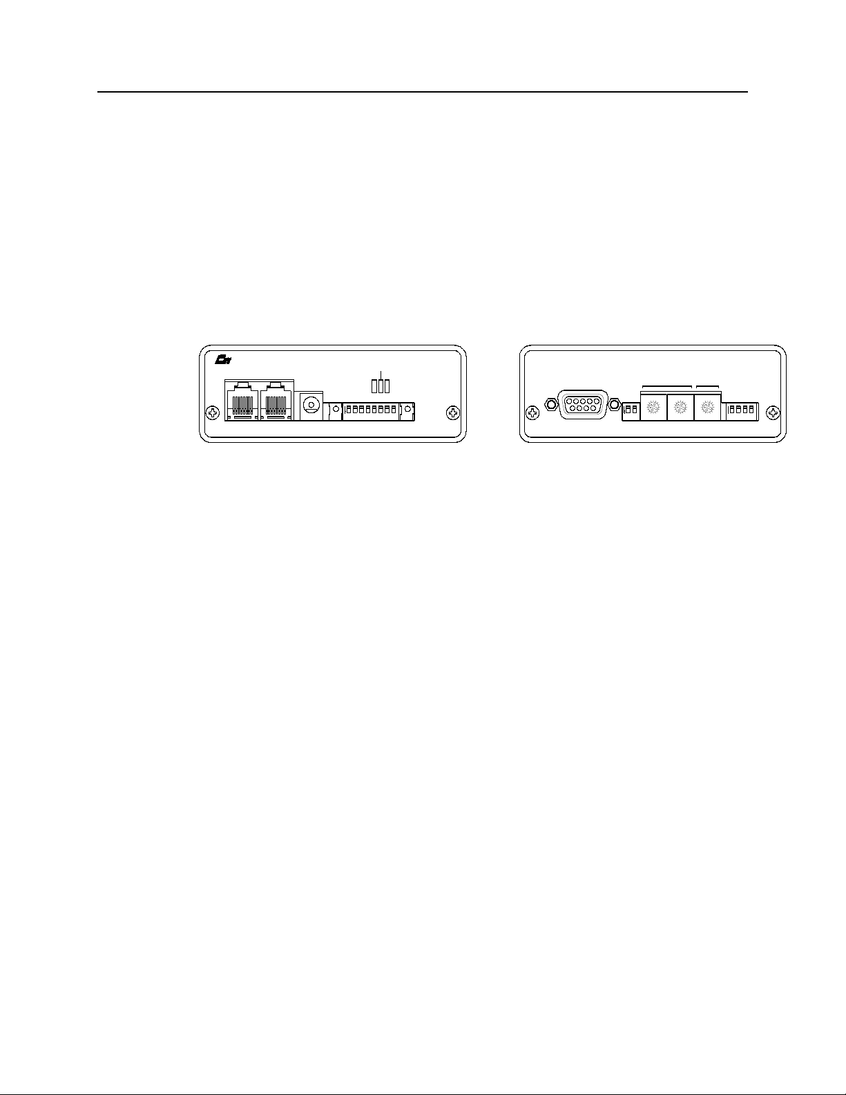
The Host Computer Interface Module (HIB) is a member of the Monitoring and
Control Network (MCN™) family of User Interface Modules. Hardware
specifications and configuration information are described in this manual.
The HIB module connects a PC, running CTI Product’s MCN Remote
Comparator Display software (MCN RCD) to the MCN network. The HIB is
used with the MCN RCD software and a Comparator I/O Module (such as a CIB
or AIB) to create a comparator display system. The comparator display system
provides monitoring and control functions for your communications system.
PRODUCTS, INC.
IN
OUTNETWORK
DC IN
RESET SVC
PWR
OPTION A
ON
12345678
ERR
ACT
Figure 1 - HIB Front and Rear View
This manual applies only to HIB modules with the unit number S2-60081-xxx,
where ‘xxx’ is the number 200 or greater. Earlier versions of the HIB module
(‘xxx’ is 100 or 101) are not covered by this manual. Manual number
S2-60427-110 describes the earlier version HIB modules. This unit number can
be found on the rear panel of the module.
1.1 Reference Documents
1. Monitoring and Control Network Comparator Display System Manual
Part Number S2-60425
2. Monitoring and Control Network Remote Comparator Display Software
Part Number S2-60428
HOST
5
SER
1234
MODE
8
7
6
5
4
6789
3
2
1
ON
12
MODULEGROUP
8
9
9
A
A
7
B
6
C
5
4
D
E
3
F
F
2
1
0
0
OPTION B
8
9
A
7
B
B
6
C
C
5
4
D
D
E
E
3
F
2
1
0
ON
1234
CA-80022-100
68-10855-210
1
Page 6

HIB Hardware Reference Theory of Operation
CTI Products, Inc.
2. Theory of Operation
The HIB module does not provide any direct monitoring or control functions. Its
purpose is to bridge the MCN network and the PC’s serial COM port.
The HIB module is used along with CTI Product’s MCN Remote Comparator
Display (MCN RCD) software (reference 2) to provide a PC based operator
station. The monitoring and control functions are performed by the MCN RCD
software.
The HIB supports multiple baud rates from 9600 baud up to 38400 baud,
selectable from the front panel.
The HIB has two modes of operation. One is local mode, where the HIB is
connected directly to the PC’s COM port. The second mode is remote mode,
where the HIB is at another location and a modem link is used to connect the HIB
to the PC’s COM port.
68-10855-210
2
Page 7

HIB Hardware Reference Specifications
CTI Products, Inc.
3. Specifications
Size 5.5” x 4.2” x 1.5” (140 x 107 x 38 mm)
Weight 16 oz (455 gm)
Temperature 0 - 50 ºC
Humidity 10 - 95% non-condensing
Module Power 10 - 32 VDC / 2 Watts max.
PC Connector 9 pin D-SUB, female
Network Connector (2) RJ-45 (1 in, 1 out)
Safety Approvals UL 1950
CSA 1950
EN 60950-1992
Emissions Compliance FCC Part 15, Class A
DOC Class A
EN55022
Susceptibility Compliance IEC 801-2
IEC 801-3
IEC 801-4
EN50082-1
Table 1 - Module Specifications
68-10855-210
3
Page 8

HIB Hardware Reference Option Switches
CTI Products, Inc.
4. Option Switches
Five sets of option switches are provided for module configuration. The module
must be power cycled or reset after these switches are set so that the options will
take effect. Table 2 describes the option switches and shows the factory defaults.
SWITCH MODULE DESCRIPTION DEFAULT
GROUP unit address setting
refer to the MCN System Manual
MODULE unit address setting
refer to the MCN System Manual
OPTION A
position 1 baud rate select 0 (see Table 3) UP
position 2 baud rate select 1 (see Table 3) DOWN
position 3 baud rate select 2 (see Table 3) UP
position 4 reserved DOWN
position 5 HIB mode select DOWN
position 6 reserved DOWN
position 7 reserved DOWN
position 8 reserved DOWN
OPTION B
position 1 reserved DOWN
position 2 reserved DOWN
position 3 reversed DOWN
position 4
SER MODE
position 1
position 2
reserved--Must be Down
reserved-- Must be UP
reserved-- Must be UP
00
0
DOWN
UP
UP
Table 2 - HIB Option Switches
The Group and Module selector switches are used to set the unit address during
module installation. See reference 1 for more information about setting these
switches.
Baud Rate baud rate select 0 baud rate select 1 baud rate select 2
9600 bps UP UP DOWN
14400 bps DOWN DOWN DOWN
19200 bps DOWN DOWN UP
38400 bps UP DOWN UP
Table 3 - Baud Rate Selector Switches
68-10855-210
4
Page 9

HIB Hardware Reference Option Switches
CTI Products, Inc.
Option A, switch 5 is used to set either local (HIB is connected directly to the PC)
or remote (HIB is connected through modems to the PC) operation.
Option A
Switch 5
HIB mode
selection
DOWN Local
UP Remote
Table 4 - Option A, Switch 5 Definition
When operating in remote mode, the HIB, after a reset, will send a programmable
initialization string to the modem. See reference 2 for more information about
programming the HIB’s modem initialization string.
68-10855-210
5
Page 10

HIB Hardware Reference Connectors
CTI Products, Inc.
5. Connectors
The NETWORK IN/OUT ports on the front of the HIB are used to connect the
HIB with other MCN modules. These ports carry both the network data signals
and the DC power for power distribution with other modules. Table 5 gives the
pinout for these connectors. Figure 2 shows the location of pin 1 for each port.
PRODUCTS, INC.
IN
PIN 1
NETWORK
OUT
DC IN
CA-80068-100
Figure 2 - Network IN/OUT Ports
Pin Function
1 DATA +
2 DATA 3+ POWER
4 No Connect
5 No Connect
6- POWER
7- POWER
8+ POWER
Table 5 - Network Connector Pinout
The DC IN port provides the primary power connection to the module. Power is
distributed through the NETWORK OUT connector to provide power to the
NETWORK IN connector of the MCN unit it is connected to. Each power
supply can power up to four units total. See reference 1 for complete details of
connections to the network and DC IN connectors.
68-10855-210
6
Page 11

HIB Hardware Reference Connectors
CTI Products, Inc.
Table 6 gives the wiring list for the PC to HIB cable, with both DB25 or DB9
connections to the PC. This cable is used when the HIB’s OPTION A, switch 5 is
set for local mode operation.
HIB HOST
Connector
DE9-female
Signal Name
HIB HOST
Cable
Connector
DE9-male Direction
PC
Cable Connector
DB25-male
PC
Cable Connector
DE9-male
DCD 1 < 8 1
RXD 2 > 3 2
TXD 3 < 2 3
DTR 4 < 20 4
Ground 5 7 5
DSR 6 > 6 6
RTS 7 < 4 7
CTS 8 > 5 8
RI 9 < 22 9
Chassis Gnd shell shell shell
Table 6 - HIB <--> PC COM Port Cable
Table 7 gives the wiring list for the HIB to modem cable. This cable is used when
the HIB’s OPTION A, switch 5 is set for remote mode operation.
HIB HOST
Connector
DE9-female
Signal Name
HIB HOST
Cable
Connector
DE9-male Direction
Modem
Cable Connector
DB25-male
DCD 1 < 8
RXD 2 > 2
TXD 3 < 3
DTR 4 < 6
Ground 5 7
DSR 6 > 20
RTS 7 < 5
CTS 8 > 4
RI 9 < 22
Chassis Gnd shell shell
Table 7 - HIB <--> Modem COM Port Cable
7
68-10855-210
Page 12

HIB Hardware Reference Mounting
CTI Products, Inc.
6. Mounting
Please refer to reference 1,
module.
Make sure that any mounting screws used to secure unit to a bracket do not
protrude into the unit’s enclosure more than 1/8 inches from the bottom surface of
the unit.
Using a larger screw that touches the pc board inside the unit may damage the unit
when it is powered. Doing so will void the unit’s warranty.
Mounting Options,
CAUTION
for details of mounting the HIB
68-10855-210
8
Page 13

HIB Hardware Reference Device Driver Installation
CTI Products, Inc.
7. Device Driver Installation
For the HIB module to operate with the MCNRCD software, the CTIHIB.SYS
device driver must be loaded by CONFIG.SYS or CONFIG.NT as shown below:
OS Configuration File
DOS c:\config.sys
Windows 9x c:\config.sys
Windows NT, 2000 c:\winnt\system32\config.nt
Windows XP c:\windows\system32\config.nt
The CTIHIB.SYS device driver provides the communication interface between
the HIB and the MCNRCD software. If this device driver is not loaded properly,
MCNRCD.EXE will not function. The name of the device driver is
CTIHIB.SYS, and it can be found on your
Display
Use a text editor to insert the following line in CONFIG.SYS or CONFIG.NT:
disk.
DEVICE=C:\CTI\CTIHIB.SYS
CTI MCN Remote Comparator
{options}
If no options are specified, the device driver will use COM1 as the default COM
port.
Options available for this driver include:
/Pn COM Port Number
Set the COM port that the HIB is connected to. The value “n” is 1 through
4 to specify COM1 through COM4 respectively. When you select the
COM port to use, make sure that no other device is using that port. Also,
make sure that the COM port’s interrupt is not being used by any other
device. If so, you must also specify the /Un option described below.
/Un Use a Different IRQ
Change the COM port interrupt request number (IRQ) to the IRQ “n”,
where “n” is between 1 and 7. If the serial port in use is COM3 or COM4,
you may want to use a unique, unused IRQ for that port. Many serial ports
and internal modems allow the selection of a non-standard IRQ such as
IRQ2 or IRQ5. The table below shows the standard COM ports supported
in a PC, along with their standard IRQ numbers.
Device IRQ
COM1 4
COM2 3
COM3 4
COM4 3
68-10855-210
9
Page 14

HIB Hardware Reference Device Driver Installation
CTI Products, Inc.
For example, if your mouse is using COM1 and IRQ4, and you want the
HIB connected to COM3, you will need to change the IRQ number used
by the device driver (possibly to 5) so that the device driver’s interrupt will
not conflict with the mouse’s interrupt.
NOTE: System operation can become very slow or may be inoperable if
the interrupt used by CTIHIB.SYS is also used by another device in your
PC.
Warning -- COM Port Conflicts
1. Be sure to use a COM port that is different from your
serial mouse port or other device.
2. The PC COM1 port shares an interrupt with COM3.
COM2 shares an interrupt with COM4. You may have
problems using COM1 and COM3 at the same time. The same
holds for COM2 and COM4.
If your mouse or other serial device is on COM1, use COM2 or
COM4 for the device driver.
If your mouse or other serial device is on COM2, use COM1 or
COM3 for the device driver.
/Wnnn Transmit Character Delay
This option is rarely used. This option adds a delay of <nnn>
microseconds between each character transmitted by the COM port. This
option is used to slow down the rate at which characters are sent because
some PC COM ports are not able to keep up with the device driver’s
transmission speed.
7.1 CTIHIB.SYS Versions
The old version of CTIHIB.SYS (dated 11/20/96) had a timing issue with NT,
2000, and XP. The new version of this file dated 4/30/02 or later solves this
problem.
10
68-10855-210
Page 15

HIB Hardware Reference Device Driver Installation
CTI Products, Inc.
7.2 Command Line Examples for CTIHIB.SYS
Below are a few examples of the CONFIG.SYS or CONFIG.NT command lines
that will load the device driver CTIHIB.SYS.
DEVICE = C:\CTI\CTIHIB.SYS
Loads the device driver and tells the driver to that the HIB is connected to
COM1. Interrupt 4 is used for this COM port.
DEVICE = C:\CTI\CTIHIB.SYS /P2
Loads the device driver and tells the driver to that the HIB is connected to
COM2.
DEVICE = C:\CTI\CTIHIB.SYS /P3 /U5
Loads the device driver and tells the driver to that the HIB is connected to
COM3 and that the COM3 interrupt has been moved to IRQ 5. The COM3
serial port hardware needs to changed so that it uses IRQ 5 also.
7.3 Device Driver Testing
After the device driver has been loaded, you will want to run a simple test to
verify that the device driver is properly configured and communicating with the
HIB module. Connect the HIB module to the COM port that you specified on the
CTIHIB.SYS command line of CONFIG.SYS (make sure the HIB’s OPTION
switch 5 is DOWN, for local mode operation). Run the file TESTHIB.BAT (this
BAT files can be found on your
This file will execute tests on the HIB and device driver to verify proper
operation. The following message will be displayed at the end if everything is
configured and operating properly:
### Device driver is properly installed and configured ###
If anything other than this message appears when the file completes, there is a
problem with your device driver configuration. Try the following to correct the
problem:
• Review your CTIHIB.SYS command line in CONFIG.SYS. Make any
necessary changes and reboot your PC.
• Verify the cabling between the COM port and the HIB.
• Verify the HIB option switches (including the baud rate). Make any
necessary changes and reset the HIB.
CTI MCN Remote Comparator Display
disk).
11
68-10855-210
Page 16

HIB Hardware Reference PC Modem Support
CTI Products, Inc.
8. PC Modem Support
8.1 DOS
The MCNRCD.exe Remote Comparator Display program runs on laptop and
desktop PCs under DOS with external modems. It will also support some internal
modems that are real modems (not WIN Modems).
8.2 Windows 95 & 98
The MCNRCD.exe Remote Comparator Display program runs on laptop and
desktop PCs using Windows 95 & 98 with external modems only. In Windows
95 & 98, Microsoft restricted DOS driver access to some of the resources like
internal modems.
8.3 Windows NT, 2000, & XP
Microsoft changed things back in Windows NT, 2000 & XP. MCNRCD.EXE
supports dial-up operation on these platforms with external or some internal
modems.
Please note that some modems may not operate properly with MCNRCD.EXE.
Some modems may require updated drivers. See the file:
"MCNRCD Modem Compatability.DOC"
on the distribution disk for the current list of modems that have been tested.
Since we cannot possibly test all combinations of PCs, Modems and operating
systems, we appreciate your feedback. Please advise us of your results using
various modems, PCs, and operating systems. We will use your feedback to
update this list periodically to help all our customers.
9. FixMouse for Windows 2000
Microsoft changed the way that that the mouse is handled in DOS windows in
Windows 2000. By default, the "Quick Edit" "Feature" is turned on. This causes
a problem with MCNRCD.EXE. Apparently, Microsoft has seen the error of their
ways and has turned Quick Edit off in Windows XP.
FixMouse.EXE has is included in the MCNRCD distribution disks to fix this
problem. Simply copy this program to the CTI directory and run FixMouse. This
will turn off the Quick Edit. Since Windows 2000 enables or disables Quick Edit
on a per-user basis, FixMouse must be run for each user.
12
68-10855-210
Page 17

HIB Hardware Reference HIB Modem Support
CTI Products, Inc.
10. HIB Modem Support
When the HIB module is configured for remote mode operation (OPTION A
switch 5 is in the UP position), a modem initialization string is sent to the modem
each time the HIB is reset or power cycled. This initialization string is stored in
the HIB’s non-volatile memory. Modems that use different command sets, may
require you to change the HIB’s default initialization string.
Configuration files for various modems are shipped with the distribution disk.
These are files with a ".HIB" suffix. See the README.TXT file on the
distribution disk for any updates.
See "Programming the HIB’s Modem Initialization String Using HIBCNFG.EXE"
in Appendix B of the MCNRCD Software Manual for details about using the .HIB
files with your modem.
Please note that when you run HIBCNFG.EXE, you must have the CTIHIB.SYS
driver loaded.
13
68-10855-210
Page 18

HIB Hardware Reference Troubleshooting
CTI Products, Inc.
11. Troubleshooting
This table is a list of troubleshooting tips specific to the HIB module. For
additional troubleshooting tips, refer to the troubleshooting section found in the
Monitoring and Control Network System Manual
Due to the high percentage of surface-mount components, the HIB is treated as a
field replaceable unit. If any system problems are the result of a malfunctioning
HIB unit, the entire unit must be replaced and returned for repair.
PROBLEM CAUSE
, reference 1.
MCNRCD is not
showing correct
status
OR
Operator cannot
FORCE VOTE or
DISABLE the
receivers
Connect the cable between the HIB and the PC. Make sure
Option A, switch 5 is in the DOWN position. If not, change the
switch and reset the HIB.
PC to HIB Data
Verify that approximately every 5 seconds, a short burst of data
occurs on the HIB HOST connector, pin 3, RXD (± 3 to ± 12 Vdc
swing). If not, verify the continuity of the cable:
DE9 pin 3 to DB25 pin 2
If the wire is OK, the PC COM port is not functioning properly.
HIB to PC Data
Verify that about every 5 seconds, a short burst of data occurs on
the PC’s COM port connector, pin 3, RXD (± 3 to ± 12 Vdc
swing). If not, verify the continuity of the cable:
DE9 pin 2 to DB25 pin 3
If the wire is OK, the HIB is not functioning properly. Replace
the HIB.
Control Signals
Verify that HIB HOST connector pins 4 (DTR) and 7 (RTS) are
active (+6 to +12 Vdc). If not, verify the continuity of the cable:
DE9 pin 4 to DB25 pin 20
DE9 pin 7 to DB25 pin 4
If the wires are OK, the PC COM port is not functioning properly.
Verify that PC COM port connector pins 5 (CTS) and 6 (DSR)
are active (+6 to +12 Vdc). If not, verify the continuity of the
cable:
DE9 pin 8 to DB25 pin 5
DE9 pin 6 to DB25 pin 6
If the wires are OK, the HIB is not functioning properly. Replace
the HIB.
System doesn't work Verify that you have the proper CTIHIB.SYS driver loaded.
68-10855-210
14
Page 19

HIB Hardware Reference Troubleshooting
CTI Products, Inc.
PROBLEM CAUSE
under Windows NT,
2000, or XP
These versions of Windows require CTIHIB.SYS dated 4/30/02
or later. After you change the file, be sure to re-boot the PC.
HIB Doesn't Work
(HIB Versions 250
& up)
Internal Modem
doesn't work
Windows 95 & 98
Internal Modem
doesn't work
Windows NT, 2000,
XP
Mouse Problems
Verify the settings of switches.
Option B position 4 MUST be DOWN.
Ser Mode Positions 1 & 2 must be UP.
(These switches have added functionality when the HIB module is
used for other applications. The switches must be set as shown
above to function as a HIB module.)
In Windows 95 & 98, Microsoft restricted DOS driver access to
some of the resources like internal modems. Internal modems are
not supported under Windows 95 & 98.
Some modems do not support DOS mode under Windows.
Some modems need an updated driver.
See the "MCNRCD Modem Compatability" file
on the distribution disk for the current list of modems that have
been tested
The "Quick Edit" feature of Windows may be turned on. This
feature causes problems with some DOS programs.
Under Windows 2000, run FixMouse.exe for each user.
For other versions of Windows, right-click on the MCNRCD &
MCNCFG program shortcuts and turn off Quick Edit under
Properties.
15
68-10855-210
 Loading...