

Page 1

MCN
Monitoring and Control Network
Hot-Standby EXB Modules
and
EXB Network Manager Software
Installation and Operator Manual
S2-61044-100
68-11707-100
Page 2

CTI Products Inc. License Agreement
MCN EXB Network Manager Software
Single-User Products
This is a legal agreement between you, the end user, and CTI Products Inc. By opening this sealed disk package, you are agreeing to be bound by the
terms of this agreement.
CTI Products Inc. Software License
1. GRANT OF LICENSE. Once you have paid the required Single-User License Fee, CTI Products Inc. grants to you the right to use one copy of the
enclosed software program (the "SOFTWARE"). You may use the SOFTWARE on any computer for which it is designed so long as no more than one
copy of the software is in operation at any one time. You must pay for additional copies of the software if more than one copy of the software will be in
use at any one time.
2. COPYRIGHT. The SOFTWARE is owned by CTI Products Inc. and is protected by United States copyright laws and international treaty provisions.
Therefore, you must treat the SOFTWARE like any other copyrighted material (e.g. a book or musical recording) except that you may make up to (3)
copies of the SOFTWARE for archival or operational purposes. You may in no event make more than (3) copies on any media, including CDs, floppy
disks, hard disks, tape, or other media. All copies of the SOFTWARE, including the original must be kept in your possession or control. You may not
copy the written materials accompanying the software.
3. OTHER RESTRICTIONS. You may not rent or lease the SOFTWARE, but you may transfer the SOFTWARE and accompanying written materials
on a permanent basis provided you retain no copies and the recipient agrees to the terms of this Agreement. You may not reverse engineer, decompile, or
disassemble the SOFTWARE. If SOFTWARE is an update, any transfer must include the update and all prior versions.
4. SOFTWARE UPDATES. Any updates to this SOFTWARE which may be furnished to the end user are subject to this Agreement unless a new
Agreement is included with the updated SOFTWARE.
STANDARD SOFTWARE LIMITED WARRANTY
LIMITED WARRANTY. CTI Products Inc. warrants that (a) the SOFTWARE will perform substantially in accordance with the accompanying written
materials for a period of one year from the date of receipt. Any implied warranties on the SOFTWARE are limited to one year.
CUSTOMER REMEDIES. CTI Products Inc.'s entire liability and your exclusive remedy shall be, at CTI Products Inc.'s option, either (a) return of the
price paid or (b) repair or replacement of the SOFTWARE that does not meet CTI Products Inc.'s Limited Warranty and which is returned to CTI
Products Inc. with a copy of your receipt. This Limited Warranty is void if failure of the SOFTWARE has resulted from accident, abuse, or
misapplication. Any replacement SOFTWARE will be warranted for the remainder of the original warranty period or one year, whichever is longer.
THESE REMEDIES ARE NOT AVAILABLE OUTSIDE OF THE UNITED STATES OF AMERICA.
NO OTHER WARRANTIES. CTI Products Inc. disclaims all other warranties, either express or implied, including but not limited to implied
warranties of merchantability and fitness for a particular purpose, with respect to the SOFTWARE, and the accompanying written materials. This limited
warranty gives you specific legal rights. You may have others, which vary from state to state.
NO LIABILITY FOR CONSEQUENTIAL DAMAGES. In no event shall CTI Products Inc. or its suppliers be liable for any damages whatsoever
(including, without limitation, damages for loss of business profits, business interruption, loss of business information, or other pecuniary loss) arising
out of the use of or inability to use this CTI Products Inc. product, even if CTI Products Inc. has been advised of the possibility of such damages.
Because some states do not allow the exclusion or limitation of liability for consequential or incidental damages, the above limitation may not apply to
you.
U.S. GOVERNMENT RESTRICTED RIGHTS
The SOFTWARE and documentation are provided with RESTRICTED RIGHTS. Use duplication, or disclosure by the Government is subject to
restrictions as set forth in subparagraph (c)(1)(ii) of The Rights in Technical Data and Computer Software clause at 52.227-7013.
Contractor/manufacturer is CTI Products Inc, 1211 West Sharon Road, Cincinnati, Ohio 45240.
This Agreement is governed by the laws of the State of Ohio.
Should you have any questions concerning this Agreement, or if you wish to contact CTI Products Inc. for any reason, please write: CTI Products Inc.,
1211 West Sharon Road, Cincinnati, Ohio 45240. (513) 595-5900
CTI Products, Inc.
1211 W. Sharon Rd.
Cincinnati, OH 45240
If you have questions about this software or the
MCN Remote Comparator Display system, call us at:
(513) 595-5900. (8:30 to 5:00 Eastern)
Information contained in this document is subject to change without notice and does not represent a commitment on the part
of CTI Products, Inc.
No part of this manual may be reproduced or transmitted in any form or by any means, electronic or mechanical, including
photocopying and recording, for any purpose without the written permission of CTI Products, Inc.
Copyright 2004 CTI Products, Inc. All rights reserved.
MCN, MCN EXB, and MCN EXB Network Manager are trademarks of CTI Products, Inc.
Other trademarks referenced are properties of their respective owners.
68-11707-100
Page 3

Hot-Standby EXB / Network Manager
Software Manual
CTI Products, Inc.
1. SYSTEM OVERVIEW.............................................................................................................................. 1
1.1 PC R
1.2 R
EFERENCE DOCUMENTS
EQUIREMENTS
.................................................................................................................................. 3
......................................................................................................................... 3
2. HOT-STANDBY EXB OPERATION....................................................................................................... 4
2.1 D
2.2 O
ORMAL LINK CONDITION
N
2.4 O
2.5 O
EFINITIONS
PERATION
............................................................................................................................................. 4
............................................................................................................................................... 5
...................................................................................................................................... 6
PEN FORWARD (PROBE
PEN REVERSE (HOLDOFF
INK CONDITION
) L
INK CONDITION
) L
............................................................................................. 7
........................................................................................... 8
3. HARDWARE INSTALLATION .............................................................................................................. 9
3.1 MCN H
3.2 S
3.3 PC N
ERIAL
ETWORK INTERFACE CARD INSTALLATION
ARDWARE
EXB D
UAL PORT USE
(EXB M
ODULES
NSTALLATION
) I
................................................................................ 9
.................................................................................................................. 9
.................................................................................... 10
4. SOFTWARE INSTALLATION.............................................................................................................. 11
5. EXBNET CONFIG CONFIGURATION PROGRAM ......................................................................... 13
5.1 I
5.2 C
5.3 C
NFORMATIONAL CUSTOM DATA
RITICAL CUSTOM DATA
ONFIGURATION PROGRAM OPERATION
5.3.1 N
5.3.2 E
5.3.3 A
5.3.4 D
5.3.5 S
5.3.6 S
5.3.7 E
5.3.8 I
5.3.9 P
5.3.10 (R
5.3.11 E
AVIGATING IN THE PROGRAM
DITING DATA
DDING AN
ELETING AN
AVING THE DATABASE
AVING COLUMN SETTINGS FOR THE CONFIGURATION PROGRAM
XPORTING THE DATABASE
MPORTING A DATABASE
RINTING DATA
E
OADING DATA
) L
XITING THE CONFIGURATION PROGRAM
............................................................................................................ 13
........................................................................................................................ 14
................................................................................................. 15
..................................................................................................... 15
.............................................................................................................................. 16
HANNEL
EXB C
EXB C
.......................................................................................................... 16
HANNEL
....................................................................................................... 16
................................................................................................................ 16
................................................ 16
.......................................................................................................... 18
.............................................................................................................. 19
............................................................................................................................ 20
.................................................................................................................... 20
..................................................................................... 20
6. NETWORK MANAGER PROGRAM OPERATION.......................................................................... 21
6.1 M
6.1.1 R
6.1.2 R
6.1.3 S
6.1.4 G
6.2 F
6.3 P
6.3.1 S
6.3.2 S
6.3.3 S
6.3.4 S
6.4 O
6.4.1 B
6.4.2 S
6.5 P
6.6 M
6.7 EXB W
6.8 S
6.8.1 N
AIN WINDOW
ESIZING WINDOW
ESIZING COLUMNS
YSTEM EVENTS WINDOW
RID DATA DEFINITION
ILE MENU
RINTER SETUP
ELECT PRINTER
ET IDENTIFICATION PREFIX
ET INITIALIZATION STRING
ET INITIALIZATION STRING
PTIONS MENU
ACKGROUND COLORS
TATUS BAR CHECK BOX
ROCESSING (ANALYSIS
ANUAL START ANALYSIS
YSTEM STATUS ANALYSIS
ORMAL STATUS
....................................................................................................................................... 21
& S
............................................................................................................................................. 25
...................................................................................................................................... 25
........................................................................................................................... 26
...................................................................................................................................... 28
) S
INK FUNCTION
............................................................................................................................ 30
.......................................................................................................................... 31
CROLL BARS
............................................................................................ 22
...................................................................................................................... 22
............................................................................................................ 22
................................................................................................................ 23
......................................................................................................... 26
1 ....................................................................................................... 27
2 ....................................................................................................... 27
................................................................................................................. 28
............................................................................................................. 29
TATUS INDICATION
....................................................................................... 29
..................................................................................................................... 29
XAMPLE SCREENS
& E
i
................................................................................. 31
68-11707-100
Page 4

Hot-Standby EXB / Network Manager
CTI Products, Inc.
Software Manual
6.8.2 M
6.8.3 M
6.8.4 R
6.8.5 M
6.8.6 R
6.8.7 R
6.8.8 S
6.8.9 S
6.8.10 C
7. APPENDIX A -- RE-INSTALLING THE
AIN NETWORK DISCONNECTED
AIN
WAN L
EMOTE MAIN
AIN (CENTRAL
EMOTE TIE LINE BAD
EMOTE STANDBY
TANDBY
TANDBY (CENTRAL
ENTRAL TIE LINE BAD
INE DISCONNECTED
AILED
EXB F
) EXB F
................................................................................................................. 36
EXB F
WAN L
INE BAD
) EXB F
......................................................................................................... 34
AILED
AILED
........................................................................................................... 38
AILED
................................................................................................................ 40
:................................................................................................. 32
................................................................................................ 33
.................................................................................................... 35
.................................................................................................. 37
.............................................................................................. 39
EXB NETWORK MANAGEMENT
PROGRAM ............. 41
8. APPENDIX B - CUSTOMER SUPPORT.............................................................................................. 42
Manual Revisions
S2-61044-100 Initial Release
ii
68-11707-100
Page 5
Hot-Standby EXB / Network Manager
Software Manual System
CTI Products, Inc. Overview
1. System Overview
Hot-Standby EXB Network Extender Modules are used when added reliability is required
in monitoring and controlling remote comparators. They work with CTI Products' MCN
Monitoring and Control network. They provide a hot-standby dual path for the
monitoring and control data.
The EXB Network Management Software runs on a PC and monitors the status of the
Hot-Standby EXB modules and links. It provides the following functions:
Status indication of EXB Modules
•
Status indication of links between modules
•
Network Management PC
Central Network Management Network
CA-80636-100
B In
Router
B Out
A Out
Central MCN
Network1
Central MCN Tie
To Additional
Central Networks
A In
To MCN PCs
Central EXBs
Net In
EXB
Net Out
Net In
EXB
Net Out
Net In
EXB
Net Out
Net In
EXB
Net Out
To Local CIBs or Routers
Port 1
Port 2
Port 1
Port 2
Port 1
Port 2
Port 1
Port 2
WAN Links
Redundant Path
Remote EXBs
Hot-Standby Channel 1
Net In
Port 1
EXB
Port 2
Net Out
Net In
Port 1
EXB
Port 2
Net Out
Hot-Standby Channel 2
Net In
Port 1
EXB
Port 2
Net Out
Net In
Port 1
EXB
Port 2
Net Out
Remote Site 1
Remote MCN Tie
To CIBs
Remote Site N
To CIBs
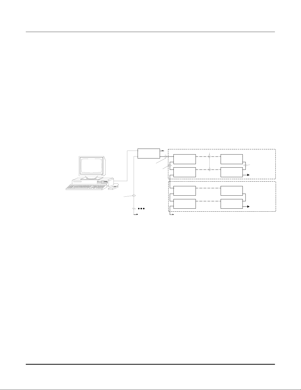
Figure 1 Hot-Standby EXB System with Network Manager PC
Figure 1 shows a typical Hot-Standby EXB system with a Network Management PC.
It shows hot-standby channels to two remote sites. Not shown on the diagram are CIB
modules at the remote sites or the MCN Remote Comparator Display (MCNRCD) PCs.
The figure shows a Network Management Router. These routers are used in large
systems that have multiple MCN networks. In these cases, the Network Management PC
sits at a higher tier than the MCNRCD PCs and manages all Hot-Standby EXB modules
that feed its MCNRCD PCs. In smaller systems with only one master central network,
the Network Management router is not needed.
Figure 1 shows Serial EXB Modules with two ports each. The system could contain a
mix of Serial and Analog (Telco) EXB modules, depending upon the WAN links
available to the remote sites. Analog (Telco) EXB Modules have only one port each. The
second port on Serial units may only be used at the Remote side.
1
68-11707-100
Page 6

Hot-Standby EXB / Network Manager
Software Manual System
CTI Products, Inc. Overview
Model Number EXB Type
S1-60603-xxx EXB-TELCO 1.25 Mbps Network
S1-60602-xxx EXB-TELCO 78 Kbps Network
S1-60656-xxx EXB-Serial 1.25 Mbps Network
S1-60655-xxx EXB-Serial 78 Kbps Network
Table 1 EXB Modules
Table 1 shows the various types of EXB modules that can be used in a system. The "xxx"
in the model number is the revision number. The revision must be 300 or above to be
used in a hot-standby system. The Hot-Standby function of these units must be enabled
with special programming provided by CTI Products, Inc. as part of a Custom Engineered
System. 78K EXB modules are typically used at the remote sites. 1.25 Mb units are
typically used at the central sites, although 78K devices could be used in some systems.
The EXB Network Management Software runs on a PC separate from the MCNRCD
PC(s). The software package includes a Network Interface card for the PC.
S1-61045 EXB Network Management Package
Includes:
S2-61005 EXB Network Management Software
90-11652 Network Interface 1.25 Mb PCI
S2-61044 Manual
S2-60617 MCN Adapter Screw Term to Dual RJ-45
If a system has multiple PC monitoring points, it can have an EXB Network Manager at
each PC location. Each Network Management PC can control only those EXBs that bring
data from remote sites to its own (Central) site.
For example, Table 2 shows a system with monitoring points at Site 1 and Site 2. A Yes
in the table indicates that the PC can monitor the appropriate "Remote" (CIB or Group)
EXBs. Notice that Site 1 cannot monitor the EXBs at its site that feed CIB data to Site 2,
and vice versa.
CIB Feeds
Site 1
Dispatch
CIBs
Site 2
Shop
CIBs
Site 3
Remote
CIBs
Site 4
Remote
CIBs
Site 1
Dispatch PC
Yes Yes Yes
Site 2
Shop PC
Yes Yes Yes
Table 2 Multiple Network Manager PCs
2
68-11707-100
Page 7

Hot-Standby EXB / Network Manager
CTI Products, Inc. Overview
Software Manual System
1.1 PC Requirements
Minimum PC requirements to run the EXB Network Management Software are:
IBM Compatible PC
•
Pentium III - 500 MHz processor or better
•
128 MB RAM
•
100 MB free disk space for program and support files
•
CD-ROM (preferable a CD-R/W drive)
•
3.5" floppy disk drive
•
SVGA adapter and monitor
•
Mouse
•
Sound Card & Speakers
•
Windows 2000 or XP Pro
•
Ethernet network card (or port)
•
1.2 Reference Documents
1. Monitoring and Control Network System Manual
Part Number S2-60425
2. MCN EXB Network Extender Manual
Part Number S2-60596
3. MCN Monitoring and Control Network Engineered System Installation Manual
Part Number S2-60650
4. Customer Specific System Diagrams and Configuration Documents
CA-xxxxx-xxx Drawings
KA-8xxxx-xxx Custom Configuration Disks
3
68-11707-100
Page 8

Hot-Standby EXB / Network Manager
CTI Products, Inc. EXB Operation
Software Manual Hot Standby
2. Hot-Standby EXB Operation
2.1 Definitions
EXB Channel Everything required to implement a
Hot-Standby EXB Link, including:
-Central Main EXB
-Central Standby EXB
-(2) Remote EXB
-Main & Standby WAN Lines
-Central MCN Tie Line
-Remote MCN Tie Line
Central Site The location of the MCNRCD PCs
and the EXB Network Manager PC.
This is the site receiving the data from the remote CIBs.
Central EXB One of the EXB modules at the central site
(where the MCNRCD PCs and the Network
Management PC are)
Central EXBs are sometimes referred to as "Network
EXBs" since they are tied to the MCN network
backbone at the MCNRCD location.
Main EXB This is the Central EXB that normally passes traffic.
Standby EXB This is the Central EXB that is normally in the Standby
mode. It only passes traffic when a fault is detected.
Remote Site This is the location of the CIB modules that are sending
their data through the EXB Channel.
Remote EXBs One of the EXB modules at the Remote Site. These
may be referred to as the "Remote Main" or "Remote
Standby" EXB to identify which WAN line it is
connected to.
They are also sometimes called "Group EXBs" or "CIB
EXBs" since they are associated with CIB modules in a
particular MCN group.
WAN Line This is the connection between the Central Site and the
Remote Site. There will be a Main Line and a Standby
Line. These lines may be analog (leased telephone
lines) or Serial Asynchronous (RS-232) lines,
depending upon what type of EXB modules are used.
4
68-11707-100
Page 9

Hot-Standby EXB / Network Manager
Software Manual Hot Standby
CTI Products, Inc. EXB Operation
Central MCN Tie Line This is the MCN network cabling between the Main
EXB and the Standby EXB. Although it is shown as a
single logical jumper in the program and on diagrams,
there may actually be a number of jumpers between the
Main and Standby EXBs, depending upon the exact
equipment mounting.
Remote MCN Tie Line This is the MCN Network Cabling between the two
remote EXB modules in a channel. Although it is
shown as a single logical jumper in the program and on
diagrams, there may actually be a number of jumpers
between the two EXBs, depending upon the exact
equipment mounting.
Control Neuron The processor in the EXB that controls the data flow.
2.2 Operation
The system normally passes data on the Main link. If a failure is detected, the
Standby half of the channel is enabled.
System testing proceeds as follows:
1. The Main EXB module continuously probes its Standby EXB over the WAN
lines.
2. The Standby EXB sends a Probe Acknowledge over the WAN lines.
3. When the Main EXB receives the Poll Acknowledge, it issues a Holdoff
command to the Standby EXB over the Central Tie Line.
4. If the Standby EXB receives the Holdoff command, it will keep its channel
switch turned off. It also sends a Holdoff Acknowledge to the Main EXB.
5. If the Standby EXB does not receive a Holdoff command within a fixed timer
period, it enables its channel switch, passing data to and from the Remote site.
The Hot-Standby EXBs can operate without intervention from the EXB Network
Management Software.
Each EXB in an EXB Channel has custom configured addresses so that the
Control Neuron in the Master and Slave EXBs know the address of each other.
These addresses are entered in the EXB Network Management Software
Configuration Program so that the EXB Network Management Software knows
the addresses of each EXB in a channel.
5
68-11707-100
Page 10
Hot-Standby EXB / Network Manager
Software Manual Hot Standby
CTI Products, Inc. EXB Operation
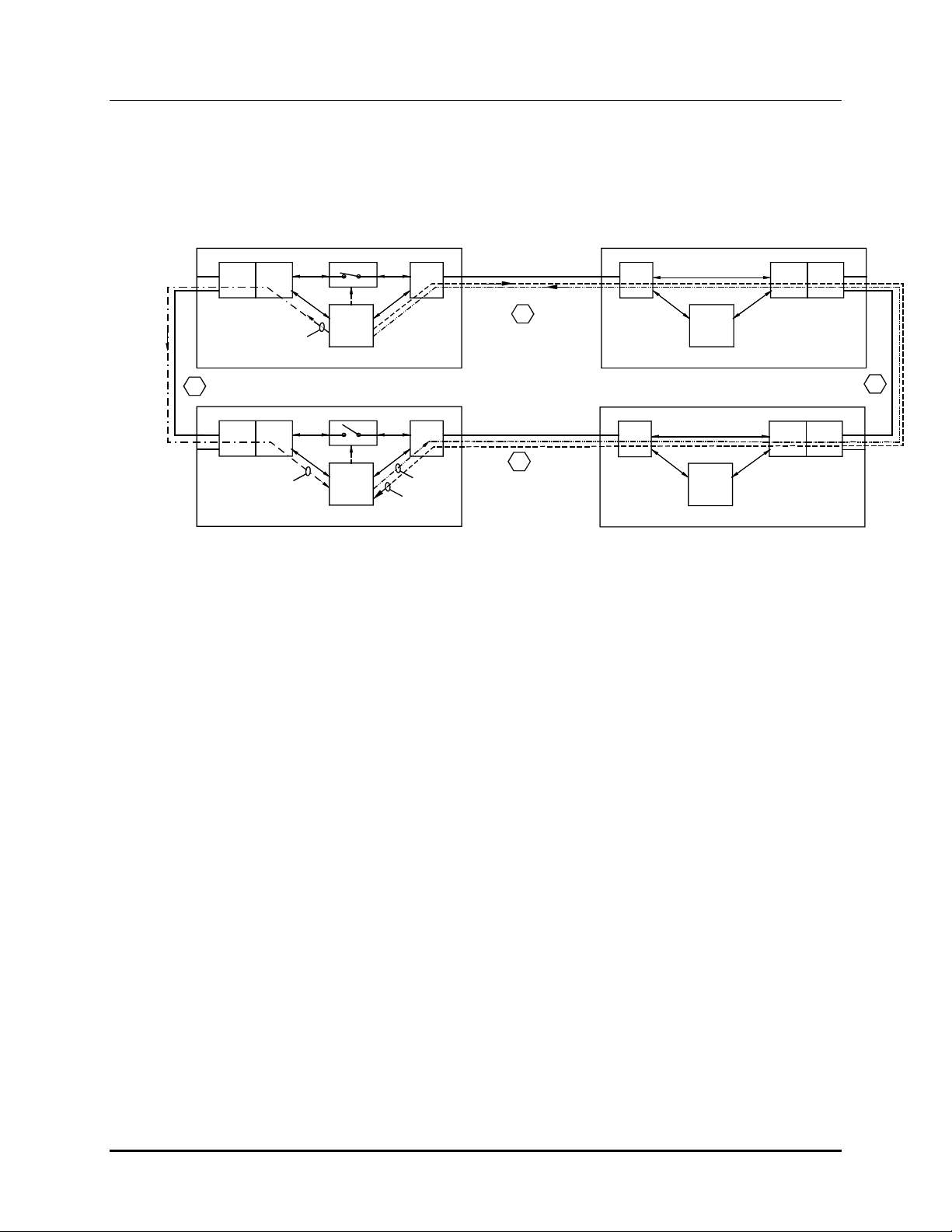
2.3 Normal Link Condition
In
Out
3. Holdoff Packet
Main
D
In
Out
3. Holdoff Packet
Standby
Central EXBs Remote EXBs
Router
BA
Router
BA
Switch
Control Neuron
4. Switch remains Open
Control Neuron
1. Probe Packet
Port 1
Port 1
2. Probe Ack
WAN Links
1. Probe Packet
2. Probe Ack
A
C
Hot Standby -- Normal Loop CA-80599-100
Port 1
Port 1
Control Neuron
Control Neuron
Figure 2 Normal Link Operation
In Normal Operation:
1. The Main EXB Control Neuron issues a Probe packet to the Standby EXB
Control Neuron
Router
A
Router
A
In
B
Out
B
In
B
Out
2. The Standby Control Neuron returns a Probe ACK.
3. When the Main EXB Control Neuron receives the Probe ACK, it issues a Holdoff
packet to the Standby EXB Control Neuron.
3a The Standby EXB Control Neuron will return a Holdoff ACK (not shown)
4. Since the Standby EXB Control Neuron received both a Probe and a Holdoff
packet, it keeps its switch open and does not pass normal MCN traffic to or from
the remote site.
6
68-11707-100
Page 11
Hot-Standby EXB / Network Manager
Software Manual Hot Standby
CTI Products, Inc. EXB Operation
2.4 Open Forward (Probe) Link Condition
In
Central EXBs Remote EXBs
Router
BA
Switch
WAN Links
A
X
Out
4. No Holdoff Packet
Main
D
Router
In
BA
Out
4. No Holdoff Packet
Standby
Control Neuron
5. Switch Closes
Control Neuron
Port 1
3. No Probe ACK Received
Port 1
Figure 3 Open Forward (Probe) Link
With an open Forward (Probe) Link Condition:
1. The Main EXB Control Neuron issues a Probe packet to the Standby EXB
Control Neuron
1. Probe Packet
2. Break in Line
C
Open Forward (Probe) Loop CB-80600-100
Port 1
Port 1
Control Neuron
Control Neuron
Router
A
Router
A
In
B
Out
B
In
B
Out
2. There is a break in the path. It is shown at point A, but it could occur at Point B
or C.
3. The Main EXB Control Neuron does not receive a Probe ACK.
4. The Main EXB Control Neuron does not issue a Holdoff packet to the Standby
EXB.
5. Since the Standby EXB Control Neuron does not receive a Probe or Holdoff
packet (timeout), it closes its switch and passes MCN packets back and forth
between the Central site and Remote Site on the bottom path.
6. If the break was at Point A (as shown), or the top Remote EXB was bad, all MCN
traffic would pass through the bottom path.
7. If break was at Point B, both EXBs would be passing data.
MCN traffic to/from the In port of the top Remote EXB would pass via the top
pair of EXBs. MCN traffic to/from the Out port of the bottom Remote EXB
would pass via the bottom pair of EXBs.
8. If the break was at Point C, the standby EXB would still close its switch, but there
would be no traffic over the bottom path. The Standby EXB would know that the
link was down because of its link layer diagnostics.
9. Since the Main EXB does not receive a Holdoff Acknowledge, it informs the
EXB Network Management Software of a problem.
7
68-11707-100
Page 12
Hot-Standby EXB / Network Manager
Software Manual Hot Standby
CTI Products, Inc. EXB Operation
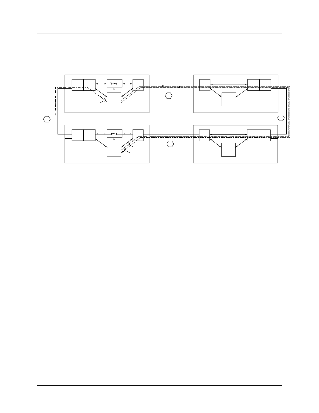
2.5 Open Reverse (Holdoff) Link Condition
Central EXBs Remote EXBs
Router
In
BA
Out
3. Holdoff Packet
Main
X
4. Break at D
Router
In
BA
Out
5. No Holdoff Packet
D
Standby
Switch
Control Neuron
6. Switch Closes
Control Neuron
Port 1
Port 1
2. Probe Ack
1. Probe Packet
WAN Links
1. Probe Packet
2. Probe Ack
A
C
Hot Standby -- Open Reverse (Holdoff) Link CC-80599-100
Port 1
Control Neuron
Port 1
Control Neuron
Router
A
Router
A
In
B
Out
B
In
B
Out
Figure 4 Open Reverse (Holdoff) Link
1. The Main EXB Control Neuron issues a Probe packet to the Standby EXB
Control Neuron
2. The Standby Control Neuron returns a Probe ACK.
3. When the Main EXB Control Neuron receives the Probe ACK, it issues a Holdoff
packet to the Standby EXB Control Neuron.
4. There is a break on the Central MCN Tie line.
5. The Holdoff Packet is not received.
6. Since the Standby EXB Control Neuron does not receive a Holdoff packet
(timeout), it closes its switch and passes MCN packets back and forth between the
Central site and Remote Site on the bottom path.
7. Both Central EXBs will have their switches closed.
The MCN traffic to and from the IN port of the Central Main (Top) EXB will pass
over the top link.
The MCN traffic to and from the OUT port of the Central Standby (Bottom) EXB
will pass over the bottom.
8. Since the Main EXB does not receive a Holdoff Acknowledge, it informs the
EXB Network Management Software of a problem.
8
68-11707-100
Page 13

Hot-Standby EXB / Network Manager
CTI Products, Inc. Installation
Software Manual Hardware
3. Hardware Installation
3.1 MCN Hardware (EXB Modules) Installation
Hardware must be installed in accordance with the following documents which
are listed from most system-specific to most generic. In the case of any
discrepancy, the documents first in the list shall take precedence.
1. Customer Specific System Diagrams and Configuration Documents
CA-xxxxx-xxx Drawings
KA-8xxxx-xxx Custom Configuration Disks
2. MCN Monitoring and Control Network
Engineered System Installation Manual
Part Number S2-60650
3. MCN EXB Network Extender Manual
Part Number S2-60596
4. Monitoring and Control Network System Manual
Part Number S2-60425
Since all EXB modules have custom addresses, they must be installed as per the
customer specific documents.
If a system is pre-configured at the factory, the EXB modules will be labeled
appropriately.
If a system is not pre-configured, the EXB modules must each be programmed
appropriately with the custom scripts provided in the Customer Configuration
Disk(s). See the instructions with the Customer Specific System Drawings.
When Serial EXB modules are used, be sure to set the Baud Rate switches on the
back of the units to the WAL Line data rate being used. 19.2K or higher is
recommended. Be sure to use Asynchronous Serial channels for the WAN line.
When Analog (Telco) EXB units are used, be sure to set the wireline 2W/4W ,TX
Level (-10 / -16 dBm), and Answer/Originate option switches as appropriate (see
Customer Specific information and the EXB manual.)
3.2 Serial EXB Dual Port Use
Serial EXBs have two serial ports. The following rules govern the use of those
ports:
1. Remote EXBs (CIB EXBs) can use 1 or 2 ports. They can feed
multiple MCNRCD display positions. If two EXB Network
Management Software PCs are running, both can see this remote EXB.
2. Central EXBs can use only 1 port.
9
68-11707-100
Page 14

Hot-Standby EXB / Network Manager
CTI Products, Inc. Installation
Software Manual Hardware
3.3 PC Network Interface Card Installation
Install the EXB Network Management Software first.
(See Section 4)
If you have completed the software driver installation, it is finally time to install
the Gesytec Easylon Network Interface card (CTI Part Number 90-11652.)
a.
b.
c.
d.
e.
f.
g.
h.
Turn off the PC and remove the power cord.
Open the PC case and locate an empty slot.
Remove the corresponding blank panel from the rear of the PC.
Insert the Network Interface card into the slot, ensuring that the
edge connectors are fully mated, and the slot in the rear panelmounting lug of the Network Interface card is aligned with the
threaded hole in the PC chassis.
Replace the screw to hold the card firmly in place.
Close the PC.
Reinsert the power cord and then restart the PC. A “New
Hardware Found” window will be displayed briefly when the
operating system recognizes the Network Interface card.
The S2-60617 MCN Adapter Screw Term to Dual RJ-45
has a pluggable screw terminal installed on it, but it fits only the
PCLTA module. The EXB Network Management Software
Network Interface uses a different terminal strip. Remove the
terminal strip from the adapter and attach the cable to the screw
terminal that ships with the Network Interface card.
i.
Connect the MCN network cable(s) to the adapter. If only one
cable is specified, connect a 1250 terminator to the second RJ-45
jack.
10
68-11707-100
Page 15

Hot-Standby EXB / Network Manager
CTI Products, Inc. Installation
Software Manual Software
4. Software Installation
This section describes the installation of the MCN EXB Network Management
Software in a PC.
If you are installing the software as an update to a previous version or re-installing
the software, you must remove the previous version first. Please refer to
Appendix A -- Re-Installing the EXB Network Management Program for
instructions.
To install the software:
1. Make sure you have Administrator privileges on the PC.
2. Close all running programs.
3. Insert the CD in the CD drive.
From the Start menu, select Run and type in:
d:\setup.exe
(where d is your CD-ROM drive letter).
4. Follow the instructions in the InstallShield install program.
5. The InstallShield program will install the program in a working directory.
The default working directory is:
c:\Program Files\CTI Products Inc\ExbNetManager.
6. After the files are copied, the PC must be re-started.
7. After you re-start the PC, turn it off again.
8. Install the Gesytec EasyLon Network Interface Card as described in section
3.3 of this manual.
9. Re-start the PC.
11
68-11707-100
Page 16

Hot-Standby EXB / Network Manager
Software Manual Software
CTI Products, Inc. Installation
10. Verify that the Gesytec Easylon Network Interface is installed correctly.
-Go to Control Panel / System Properties / Device Manager.
-Click on LON Adapters / Gesytec.
-Go to the Advanced Tab.
-Click on the Adapter Name.
-Be sure it is set for LPP1. If not, change it to read LPP1.
-Close the windows.
Figure 5 Network Interface Properties Window
11. If the custom files have been factory-generated for the EXB Network
Management Software, they will be on the Customer Specific Disk(s). Copy
the following file to the working directory:
MCNChannels.dat
12. If the custom files were not included, run the EXBNet Config program to
generate the channel configuration. Use the data furnished by CTI products,
Inc.
The InstallShield program will add shortcuts for the EXBNet Config program and
the EXB Network Manager programs to the CTI Products folder on the desktop.
12
68-11707-100
Page 17

Hot-Standby EXB / Network Manager
CTI Products, Inc. Program
Software Manual Configuration
5. EXBNet Config Configuration Program
This program allows you to enter or modify data for each EXB Channel in your
system. It also allows you to export or import that data to or from .CSV files. It
should only be used by system administrators.
EXB Network Management Software program to malfunction.
5.1 Informational Custom Data
This data will be displayed on the screen and on error reports. It is used to help
you diagnose system problems.
The User Defined data may be changed as required. Other data should contain at
least the data that is specified in the Customer Specific information package.
MCN Network (Numeric)
(Informational. Should match Network Name in Customer Specific package)
Radio Channel (User Defined)
(Informational. Identifies which radio channel traffic is being passed through
this EXB channel.)
Improper data can cause the
Remote MCN Group Number
(Informational. Should match Remote Group Number in Customer Specific
package)
Main EXB Name
(Informational. Should match Central Main EXB Name in Customer Specific
package and on the label for the Main EXB for this channel))
Main (WAN) Line Name (User Defined)
(Informational. Main Phone Line, Microwave, or T1 channel identifier)
Main Remote EXB Name
(Informational. Should match Main Remote EXB Name in Customer Specific
package and on the label for the Main Remote EXB for this channel))
Main Remote EXB Port Number
(Informational. Always port 1 for Analog (Telco) EXBs.
For Serial EXBs, this indicates which port is being used on this link.)
Standby EXB Name
(Informational. Should match Central Standby EXB Name in Customer
Specific package and on the label for the Standby EXB for this channel))
Standby (WAN) Line Name (User Defined)
(Informational. Standby Phone Line, Microwave, or T1 channel identifier)
Standby Remote EXB Name
(Informational. Should match Standby Remote EXB Name in Customer
Specific package and on the label for the Standby Remote EXB for this
channel))
13
68-11707-100
Page 18

Hot-Standby EXB / Network Manager
CTI Products, Inc. Program
Standby Remote EXB Port Number
(Informational. Always port 1 for Analog (Telco) EXBs.
For Serial EXBs, this indicates which port is being used on this link.)
Software Manual Configuration
5.2 Critical Custom Data
This data is the system-specific data for each of the EXB modules. It tells the
EXB Network Management Software the appropriate addresses for each EXB
module.
This data must be entered exactly as specified in the
Customer Specific Package shipped by CTI Products.
Main Near Router Subnet & Node (Hex)
Address for MCN Network side of internal router in Central Main EXB
Main Far Router Subnet & Node (Hex)
Address for WAN side of internal router in Central Main EXB
Main Control Subnet & Node (Hex)
Address for Control Neuron (Control processor) in Central Main EXB
Main Remote Near Router Subnet & Node (Hex)
Address for WAN side of internal router in Main Remote EXB
Main Remote Far Router Subnet & Node (Hex)
Address for MCN Network side of internal router in Main Remote EXB
Main Control Subnet & Node (Hex)
Address for Control Neuron (Control processor) in Main Remote EXB
Standby Near Router Subnet & Node (Hex)
Address for MCN Network side of internal router in Central Standby EXB
Standby Far Router Subnet & Node (Hex)
Address for WAN side of internal router in Central Standby EXB
Standby Control Subnet & Node (Hex)
Address for Control Neuron (Control processor) in Central Standby EXB
Standby Remote Near Router Subnet & Node (Hex)
Address for WAN side of internal router in Standby Remote EXB
Standby Remote Far Router Subnet & Node (Hex)
Address for MCN Network side of internal router in Standby Remote EXB
Standby Control Subnet & Node (Hex)
Address for Control Neuron (Control processor) in Standby Remote EXB
14
68-11707-100
Page 19

Hot-Standby EXB / Network Manager
CTI Products, Inc. Program
Note that "Near" and "Far" refer to the sides of the internal router that are closer or
further from the EXB Network Management Software PC.
Software Manual Configuration
5.3 Configuration Program Operation
When the program is started, it will come up in one of two states:
1. A Blank screen if MCNChannels.dat is missing or blank
2. A screen with channel information if MCNChannels.dat has valid data.
Figure 6 Typical Configuration Screen
5.3.1 Navigating in the Program
The program functions like a typical Windows program.
move between cells
To
see a portion of the database that is off the screen,
To
To access
Help).
To access the
along with the indicated shortcut.
menu functions
bottom buttons
, use the mouse or arrow keys
use the Scroll bar(s).
, use the mouse hit Alt-F (for File) or Alt-H (for
, click on them with a mouse or hit the Ctrl key
15
68-11707-100
Page 20

Hot-Standby EXB / Network Manager
CTI Products, Inc. Program
Software Manual Configuration
To change a
the top row. The cursor will change to a double arrow. Drag the column to
the desired width.
column width
5.3.2 Editing Data
To Edit data, move the cursor to the field and click. Enter data from the keyboard.
When you are finished in that field, hit Enter or any of the cursor arrows to move
to another field.
Some fields are limited to numeric or Hex values. If you type a non-numeric or
non-hex value, a warning window will pop up.
Figure 7 Input Error Window
5.3.3 Adding an EXB Channel
To add an EXB channel, hit the
channel will be added to the bottom of the list.
, move your mouse over a column separator into
Add Channel
button or type <Ctrl-A>. A blank
5.3.4 Deleting an EXB Channel
To delete an EXB channel, move the cursor to the channel you want to delete. Hit
the
Delete Channel
button or type <Ctrl-D>.
5.3.5 Saving the Database
To save the database, hit the
Only one custom configuration file is used in the EXB Network Management
Software, MCNChannels.dat. The configuration program saves to this file.
You must save the database before you exit.
The program does not prompt you to save changes.
When you Save a database, the EXB Network Management Software program
will use that database the next time is started.
Save Database
Warning
button or type <Ctrl-S>.
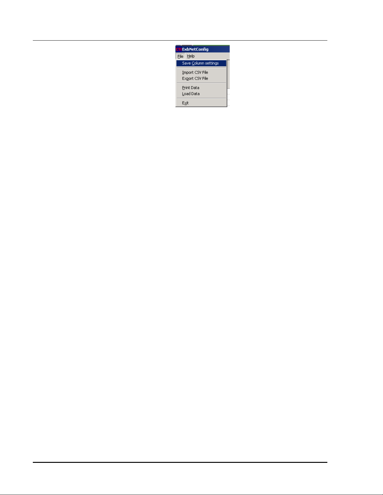
5.3.6 Saving Column Settings for the Configuration Program
To save the column settings used in the Configuration program, select the
Column Settings
option from the
File
menu:
Save
16
68-11707-100
Page 21
Hot-Standby EXB / Network Manager
Software Manual Configuration
CTI Products, Inc. Program
Figure 8 File / Save Column Settings
17
68-11707-100
Page 22

Hot-Standby EXB / Network Manager
Software Manual Configuration
CTI Products, Inc. Program
5.3.7 Exporting the Database
You can export a database to a Comma Separated Variables (.CSV) file for use
with a program such as Excel.
Another use for the Export feature is if you are making changes to your database
but don't want to use them right away. You can save the new version of the
database to a temporary CSV file and import it later and save it later to the main
database.
To Export a database, select the
Export CSV File
Figure 9 File / Export CSV File Menu
You will be prompted for a file name.
option from the
File
menu.
Figure 10 Export Window
Enter the file name and hit the
18
Save
button.
68-11707-100
Page 23

Hot-Standby EXB / Network Manager
Software Manual Configuration
CTI Products, Inc. Program
5.3.8 Importing a Database
You can import a database from a Comma Separated Variables (.CSV) file.
To Import a database, select the
Import CSV File
Figure 11 File / Import CSV File Menu
You will be prompted for a file name.
option from the
File
menu.
Figure 12 Import CSV Window
Select the appropriate file, and hit the
button. The database will appear on
Open
the screen. If you want to use this database, be sure to hit the Save Database
button on the bottom of the screen.
19
68-11707-100
Page 24

Hot-Standby EXB / Network Manager
CTI Products, Inc. Program
Software Manual Configuration
5.3.9 Printing Data
You can print the data to a printer. It is recommended that you use an 11 x 17"
sheet in landscape mode. (It may be better to export the data in CSV format and
print it from a spreadsheet.)
To Print the data, select the
Print Data
option from the
5.3.10 (Re) Loading Data
If you have made a mistake and want to re-load the data from the main data file
(MCNChannels.dat), select the
Figure 13 File / Load Data Menu
Load Data
5.3.11 Exiting the Configuration Program
To exit the program, select the
option from the
Exit
File
option from the
File
menu.
File
menu.
menu.
Figure 14 File / Exit Menu
Warning
If you have made changes that you want to keep,
you must save the database before you exit.
The program does not prompt you to save changes.
20
68-11707-100
Page 25

Hot-Standby EXB / Network Manager
CTI Products, Inc. Program Operation
Software Manual Network Manager
6. Network Manager Program Operation
The EXB Network Management Software program will:
1. Display the status of the Hot-Standby EXB system.
2. Log Errors to Disk and/or Printer
3. Perform (limited) diagnostics to help isolate problems.
6.1 Main Window
The main window opens with a list of all the EXB channels defined in the data
base.
Figure 15 -- EXB Network Management Software Main Window
The display is configured to display each EXB channel in a text grid similar to the
channel diagram as shown in Figure 2.
21
68-11707-100
Page 26

Hot-Standby EXB / Network Manager
CTI Products, Inc. Program Operation
Software Manual Network Manager
6.1.1 Resizing Window & Scroll Bars
The window may be re-sized as any standard Windows program by dragging one
of the window edges or corners.
If the window is too small for the entire system, scroll bar(s) will appear.
6.1.2 Resizing Columns
Columns may be re-sized to fit the data better. To change a
your mouse over a column separator into the top row. The cursor will change to a
double arrow. Drag the column to the desired width. If you want to save the
column widths, use the
File / Save Column Settings
command.
column width
, move
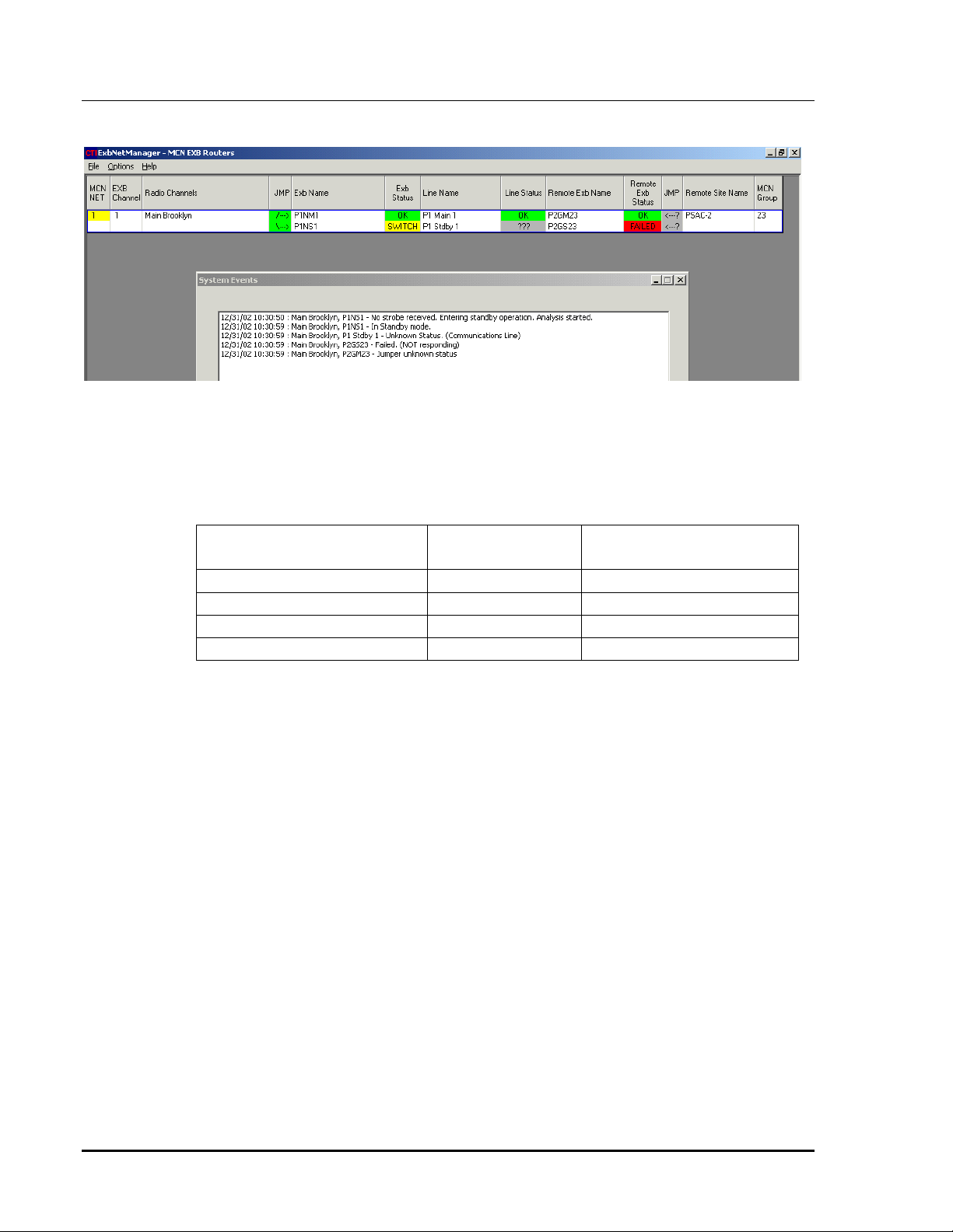
6.1.3 System Events Window
When the state of an EXB unit changes, a System Events window will appear with
information about the event.
Hitting the Minimize button will keep the current data. The next event will bring
up the window again with the new data added to the end of the original data.
Hitting the OK button will clear and close the window. The next event will bring
up the window with only the new event data.
22
68-11707-100
Page 27

Hot-Standby EXB / Network Manager
Software Manual Network Manager
CTI Products, Inc. Program Operation
6.1.4 Grid Data Definition
Each EXB channel is shown as two lines. The channels are separated from each
other by a heavy blue line. The top row for each channel is for the Main path, and
the bottom row is for the Standby path. (The status colors shown below are the
default colors as shipped with the software. If you change the colors all bets are
off.)
MCN Net
EXB Channel
Radio Channel
JMP (Left)
EXB Name (Left)
The MCN Network that is defined in the database for this
EXB Channel.
EXB Channel number defined in the database
Radio channel associated with this EXB channel as defined
in the database.
Shows the status of the Central MCN Tie lines.
Green /
\
Æ
Red X
ÆÆÆÆ
Gray ???
ÆÆÆÆ
There is a problem but the program
(Looks like a jumper)
Connection is OK
The connection is broken
doesn't have enough information to
determine the status of the jumper.
Remember that the MCN Tie line as shown here is a logical
connection. Physically, this tie line can be a series of
jumpers, depending upon the actual equipment racking.
Shows the Central EXB names as defined in the database.
The top name in a pair of rows is the Central Main EXB.
The bottom name is the Central Standby EXB.
EXB Status (Left)
Shows the status of the Central EXBs.
The top status in a pair of rows is for the Main EXB.
The bottom status is the Central Standby EXB.
Green OK
Functioning Properly
Main EXB = passing data
Standby EXB = not passing data
(switch off)
Red Failed
Gray ???
Program cannot talk to EXB
There is a problem but the program
doesn't have enough information to
determine the true status of the EXB
23
68-11707-100
Page 28

Hot-Standby EXB / Network Manager
Software Manual Network Manager
CTI Products, Inc. Program Operation
Line Name
Line Status
Remote EXB Name
Yellow Switch
(Standby EXB only)
The Standby EXB is not receiving a
Holdoff command and has turned its
network switch on.
WAN Line Name for the Main (top) or Standby (bottom)
EXB as defined in the database. This is typically a
telephone microwave or T1 line number which can be used
to troubleshoot the system.
Status of the WAN Line for the Main (top) or Standby
(bottom) EXB as determined by the program
Green OK
Red Error
Gray ???
Functioning Properly
Line bad
There is a problem but the program
doesn't have enough information to
determine the true status of the line
Shows the Remote EXB names as defined in the database.
The top name in a pair of rows is the Remote Main EXB.
The bottom name is the Remote Standby EXB.
Remote EXB Status
JMP (Right)
Remote Site Name
MCN Group
Shows the status of the Remote EXBs.
The top status is for the Remote Main EXB.
The bottom status is the Remote Standby EXB.
Green OK
Red Failed
Gray ???
Functioning Properly
Program cannot talk to EXB
There is a problem but the program
doesn't have enough information to
determine the true status of the EXB
Remote units do not have the "Switch" function.
Shows the status of the Remote MCN Tie lines.
Same status indications as the JMP (Left) column.
Shows the Remote Site Name as defined in the database.
There may be multiple EXB channels to a particular remote
site, serving various radio channels, depending upon the
network configuration.
MCN Group Number for the CIBs attached to this EXB
channel, as defined in the database.
24
68-11707-100
Page 29

Hot-Standby EXB / Network Manager
CTI Products, Inc. Program Operation
Software Manual Network Manager
6.2 File Menu
The File Menu on the Main Window has the following options:
Figure 16 Network Manager File Menu
Save Column Settings
Log Events to Disk
Log Events to Printer
Printer Setup
Exit
6.3 Printer Setup
The EXB Network Management Software program can send error events to a
printer. The
up its setup strings.
Saves the current column settings.
These settings will be used the next time the program is
re-started.
This check-box option turns on disk logging.
The logging file is
This check-box option turns on printer logging.
You must set up a printer with the
command.
Selects a printer to use and appropriate setup strings.
Exits the program.
File / Printer Setup
EventLog.txt
menu item allows you to select a printer and set
.
Printer Setup
Figure 17 Printer Setup Menu
25
68-11707-100
Page 30
Hot-Standby EXB / Network Manager
CTI Products, Inc. Program Operation
Software Manual Network Manager
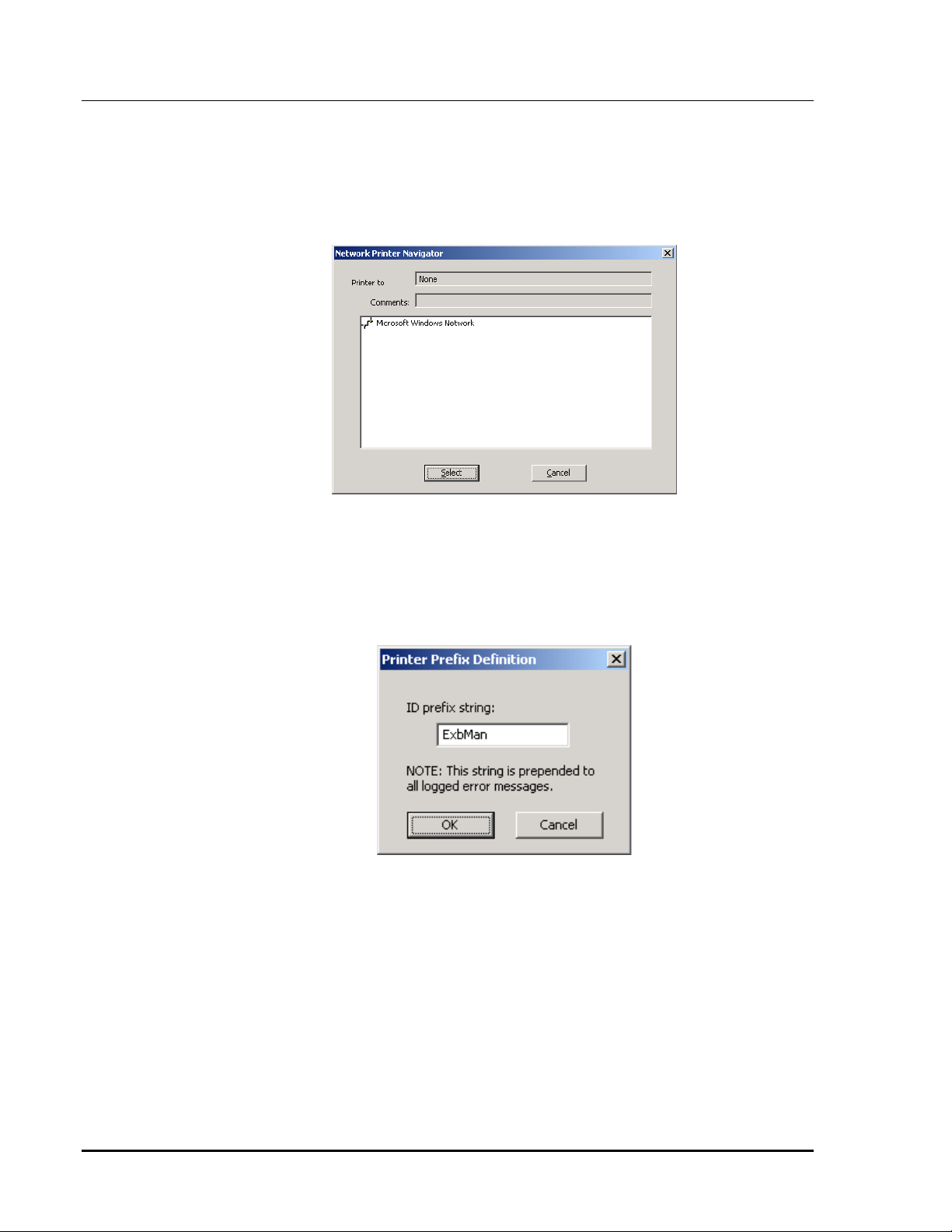
6.3.1 Select Printer
Select Printer
The
printer. Typically, dot-matrix line printers are used, since error events are only a
few lines long and do not generate a whole sheet of data.
dialog box allows you to select either a local or a network
Navigate to the desired printer and hit the
Figure 18 Selet Printer Dialog Box
6.3.2 Set Identification Prefix
If the program is using a shared printer, you may wish it to send an identification
prefix before each line of data. In this way, you can tell which PC each line of
data came from. Use the
Select
button.
Set Identification Prefix
dialog box for this purpose.
Figure 19 Set Identification Prefix Dialog Box
26
68-11707-100
Page 31
Hot-Standby EXB / Network Manager
CTI Products, Inc. Program Operation
Software Manual Network Manager
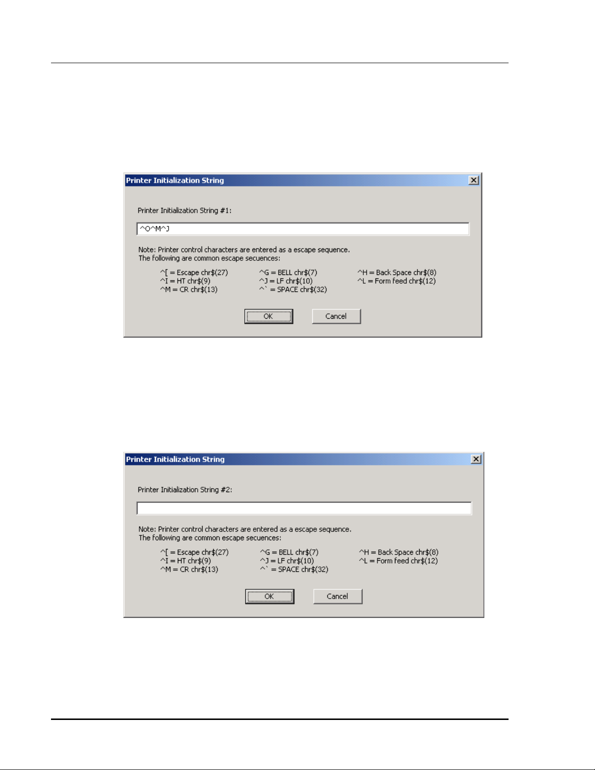
6.3.3 Set Initialization String 1
The program can send two initialization prefixes whenever it starts.
Initialization String 1 is typically used to put the printer into compressed print
mode.
Use the
String.
Set Initialization String 1
Figure 20 Set Initialization String 1 Dialog Box
6.3.4 Set Initialization String 2
Initialization String 2 is typically used to generate column headings when the
program starts.
Use the
String.
Set Initialization String 2
dialog box to enter the first Initialization
dialog box to enter the second Initialization
Figure 21 Set Initialization String 2 Dialog Box
27
68-11707-100
Page 32

Hot-Standby EXB / Network Manager
CTI Products, Inc. Program Operation
Software Manual Network Manager
6.4 Options Menu
From the
status conditions and enable or disable the
Options
menu, you can change the
Figure 22 EXB Network Manager Options Menu
Background Colors
Status Bar
.
for the various
6.4.1 Background Colors
Background Colors
The
the following status conditions:
Error
Caution
menu allows you to change the background colors of
Normal
Unknown
Processing
Figure 23 EXB Network Manager Background Colors Menu
Note that the colors for the status indications shown in this manual are based upon
the default color configuration that ships with the software.
28
68-11707-100
Page 33

Hot-Standby EXB / Network Manager
CTI Products, Inc. Program Operation
Selecting an item will bring up the Color Selection Dialog Box.
Figure 24 Color Selection Dialog Box
Software Manual Network Manager
6.4.2 Status Bar Check Box
This check box turns the Status Bar on the bottom of the screen On & Off.
6.5 Processing (Analysis) Status Indication
The program will scan each EXB channel to check its status. The EXB Channel
field will change color to indicate which channel the program is analyzing.
6.6 Manual Start Analysis
To force the program to analyze a particular channel, double-click anywhere in
that EXB channel row. The
Analysis
. The program will Queue up that channel for analysis next.
Start Analysis
window will appear. Click
on Start
Figure 25 Start Analysis Window
(The Wink option is not enabled since the user didn't click directly on an EXB
name, but rather on the channel number.)
29
68-11707-100
Page 34

Hot-Standby EXB / Network Manager
Software Manual Network Manager
CTI Products, Inc. Program Operation
6.7 EXB Wink Function
Since there can be many EXB modules in a system, it is helpful to be able to
verify which physical EXB module corresponds to the unit on the screen. The
program has a Wink EXB function that will help identify an EXB in the field.
When the Wink EXB function is activated, the PWR LED on the EXB module
will wink.
Figure 26 Start Analysis / Wink EXB Window
To Wink an EXB, double-click on the desired EXB name. The
Wink window will appear. Click on
Wink.
.
Start Analysis
(Since the EXB Name is in the channel row, the Start Analysis option is also
enabled.)
/
30
68-11707-100
Page 35

Hot-Standby EXB / Network Manager
CTI Products, Inc. Program Operation
Software Manual Network Manager
6.8 System Status Analysis & Example Screens
The EXB Network Management Software program tries to analyze the system to
the best of its ability. It presents its best guess as to what is wrong in the system.
When a Main EXB notices a change in state of its Standby EXB, it will notify the
program. The program will start an analysis on that EXB channel.
It will try to communicate to all EXB units first in the forward direction
(Clockwise -- the Probe direction as shown in Figure 3).
It will then try to communicate to all EXB units first in the reverse direction
(Counter-Clockwise -- the Holdoff direction as shown in Figure 3).
It can take about 5-10 seconds to analyze a failed EXB channel.
Based upon the responses, the program will then determine what the most likely
failure is. Do not take its recommendations as absolute truth. Sometimes there
are other failures that can result in the same display. The program is presenting
the most likely problem. Some alternate problems are shown in the following
status displays.
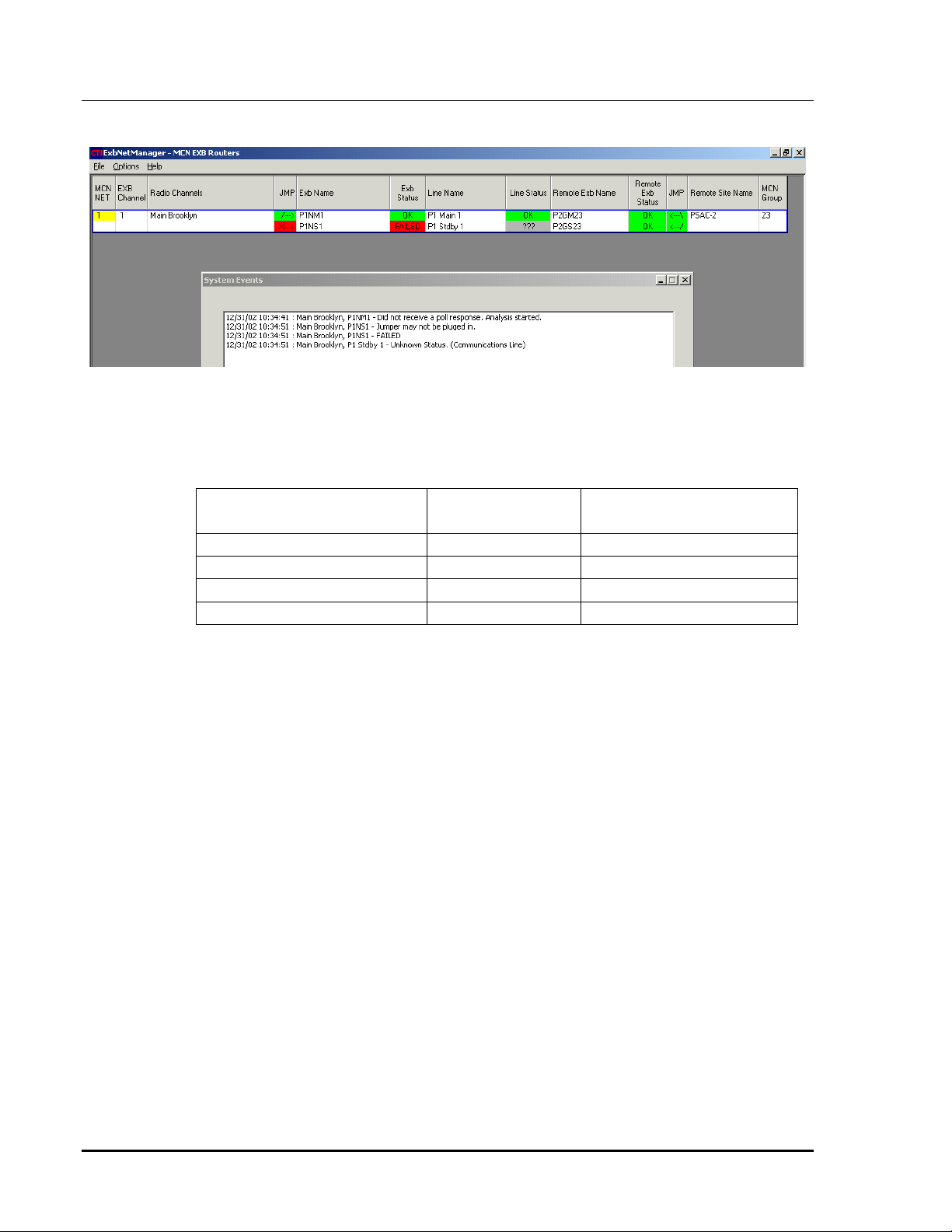
6.8.1 Normal Status
Figure 27 Normal Status
When everything is normal, all status fields are Green (or the Normal color you
have defined).
31
68-11707-100
Page 36

Hot-Standby EXB / Network Manager
Software Manual Network Manager
CTI Products, Inc. Program Operation
6.8.2 Main Network Disconnected:
Figure 28 Main Network Disconnected
When the EXB Network Management Software PC is disconcerted from the EXB
channel, it cannot see any of the EXB modules.
This could be a disconnected cable or a Network Management Router problem.
32
68-11707-100
Page 37

Hot-Standby EXB / Network Manager
Software Manual Network Manager
CTI Products, Inc. Program Operation
6.8.3 Main WAN Line Disconnected
Figure 29 Main WAN Line Disconnected
Since the loop is not complete, the Standby EXB turns on its network switch to
pass traffic over the Standby WAN line.
In this condition, the program can talk to the units as follows:
EXB Forward
(Clockwise)
Reverse
(Counter-Clockwise)
Main (Central) Yes No
Standby (Central) No Yes
Remote Standby No Yes
Remote Main No Yes
Based upon this, the program determines that the Main WAN Line is bad.
Other possible causes for this display could be:
1. A bad cable from one of the EXBs to the Main WAN line.
2. Bad Main Central or Main Remote EXB Module.
Possibly a bad modem in an Analog / Telco EXB unit
Possibly a bad serial port on a Serial EXB unit.
33
68-11707-100
Page 38

Hot-Standby EXB / Network Manager
Software Manual Network Manager
CTI Products, Inc. Program Operation
6.8.4 Remote Main EXB Failed
Figure 30 Remote Main EXB Failed
Since the loop is not complete, the Standby EXB turns on its network switch to
pass traffic over the Standby WAN line.
In this condition, the program can talk to the units as follows:
EXB Forward
(Clockwise)
Reverse
(Counter-Clockwise)
Main (Central) Yes No
Standby (Central) No Yes
Remote Standby No Yes
Remote Main No No
Based upon this, the program determines that the Remote Main EXB unit is bad.
Other possible causes for this display could be:
1. No power to the Remote Main EXB module.
2. A bad Main WAN line AND a bad Remote tie line.
(Highly unlikely that two failures have occurred.)
However, the program flags these lines as questionable since it cannot
determine that they are good.
34
68-11707-100
Page 39

Hot-Standby EXB / Network Manager
Software Manual Network Manager
CTI Products, Inc. Program Operation
6.8.5 Main (Central) EXB Failed
Figure 31 Main (Central) EXB Failed
Since the loop is not complete, the Standby EXB turns on its network switch to
pass traffic over the Standby WAN line.
In this condition, the program can talk to the units as follows:
EXB Forward
(Clockwise)
Reverse
(Counter-Clockwise)
Main (Central) No No
Standby (Central) No Yes
Remote Standby No Yes
Remote Main No Yes
Based upon this, the program determines that the Central Main EXB unit is bad.
Other possible causes for this display could be:
1. No power to the Central Main EXB module.
2. A bad Main WAN line AND a bad Central tie line.
(Highly unlikely that two failures have occurred.)
However, the program flags these lines as questionable since it cannot
determine that they are good.
35
68-11707-100
Page 40

Hot-Standby EXB / Network Manager
Software Manual Network Manager
CTI Products, Inc. Program Operation
6.8.6 Remote Tie Line Bad
Figure 32 Remote Tie Line Bad
Since the loop is not complete, the Standby EXB turns on its network switch to
pass traffic over the Standby WAN line.
In this condition, the program can talk to the units as follows:
EXB Forward
(Clockwise)
Reverse
(Counter-Clockwise)
Main (Central) Yes No
Remote Main Yes No
Standby (Central) No Yes
Remote Standby No Yes
Based upon this, the program determines that the Remote Tie Line is bad.
36
68-11707-100
Page 41
Hot-Standby EXB / Network Manager
Software Manual Network Manager
CTI Products, Inc. Program Operation
6.8.7 Remote Standby EXB Failed
Figure 33 Remote Standby EXB Failed
Since the loop is not complete, the Standby EXB turns on its network switch to
pass traffic over the Standby WAN line.
In this condition, the program can talk to the units as follows:
EXB Forward
(Clockwise)
Reverse
(Counter-Clockwise)
Main (Central) Yes No
Remote Main Yes No
Standby (Central) No Yes
Remote Standby No No
Based upon this, the program determines that the Remote Standby EXB unit is
bad.
Other possible causes for this display could be:
1. No power to the Remote Standby Main EXB module.
2. A bad Standby WAN line AND a bad Remote tie line.
(Highly unlikely that two failures have occurred.)
However, the program flags these lines as questionable since it cannot
determine that they are good.
37
68-11707-100
Page 42

Hot-Standby EXB / Network Manager
Software Manual Network Manager
CTI Products, Inc. Program Operation
6.8.8 Standby WAN Line Bad
Figure 34 Standby WAN Line Bad
Since the loop is not complete, the Standby EXB turns on its network switch to
pass traffic over the Standby WAN line.
In this condition, the program can talk to the units as follows:
EXB Forward
(Clockwise)
Reverse
(Counter-Clockwise)
Main (Central) Yes No
Remote Main Yes No
Remote Standby Yes No
Standby (Central) No Yes
Based upon this, the program determines that the Standby WAN Line is bad.
Other possible causes for this display could be:
1. A bad cable from one of the Standby EXBs to the Standby WAN line.
2. Bad Standby or Standby Remote EXB Module.
Possibly a bad modem in an Analog / Telco EXB unit
Possibly a bad serial port on a Serial EXB unit.
38
68-11707-100
Page 43
Hot-Standby EXB / Network Manager
Software Manual Network Manager
CTI Products, Inc. Program Operation
6.8.9 Standby (Central) EXB Failed
Figure 35 Standby (Central) EXB Failed
The program cannot talk to the Central Standby EXB unit.
In this condition, the program can talk to the units as follows:
EXB Forward
(Clockwise)
Reverse
(Counter-Clockwise)
Main (Central) Yes No
Remote Main Yes No
Remote Standby Yes No
Standby (Central) No No
Based upon this, the program determines that the Central Standby EXB unit is
bad.
Other possible causes for this display could be:
1. No power to the Central Standby EXB Unit
2. A bad cable Central Tie Line AND Standby WAN line
(Unlikely double failure)
3. A bad cable Central Tie Line AND Remote Standby EXB WAN problem
(Bad internal modem or RS-232 port)
(Unlikely double failure)
39
68-11707-100
Page 44

Hot-Standby EXB / Network Manager
Software Manual Network Manager
CTI Products, Inc. Program Operation
6.8.10 Central Tie Line Bad
Figure 36 Central Tie Line Bad
Since the loop is not complete, the Standby EXB turns on its network switch to
pass traffic over the Standby WAN line.
In this condition, the program can talk to the units as follows:
EXB Forward
(Clockwise)
Reverse
(Counter-Clockwise)
Main (Central) Yes No
Remote Main Yes No
Remote Standby Yes No
Standby (Central) Yes No
Based upon this, the program determines that the Central Tie Line to the Standby
EXB unit is bad.
Note that if the MCNRCD PCs at the central site are connected to the Standby
EXB, they may actually be receiving data via the Standby path.
Other possible causes for this display could be:
1. Bad MCN Network port on the Standby EXB unit.
40
68-11707-100
Page 45

Hot-Standby EXB / Network Manager
CTI Products, Inc. Re-Installing the Program
Software Manual Appendix A
7. Appendix A -- Re-Installing the
Management
InstallShield does not always properly install a newer version of the
Network Management Software
installing an update for the program , you must remove the old version of the
program first. Follow these instructions:
1. Close the
2. Remove the old version of the
3. Install the
Program
program over an old version. If you are
EXB Network Management
EXB Network Management
Start Æ Settings Æ Control Panel Æ Add/Remove Programs
-Select the
-Hit Change/Remove.
-Select Remove
-Hit Next.
Software Installation.
EXB Network Management
EXB Network Management
program.
program using the steps in Section 4,
EXB Network
EXB
program :
program.
41
68-11707-100
Page 46

Hot-Standby EXB / Network Manager
CTI Products, Inc. Customer Support
Software Manual Appendix B
8. Appendix B - Customer Support
If you need help in setting up your system, call one of our engineers at:
(513) 595-5900.
Ask to speak to a CTI Products, Inc. engineer.
Our hours are from 8:30 to 5:00 Eastern time.
42
68-11707-100
Page 47

68-11707-100
Page 48

68-11707-100
 Loading...