

Page 1

MCN Monitoring and Control Network
Comparator Display System
Comparator I/O Module
CIB
Hardware Reference Manual
S2-60426-135
Note:
Jumpers & switch settings vary depending upon the
type of comparators or voters used.
Be sure to verify jumper and switch settings before
connecting the units to your comparators or voters.
Be sure to set the rotary address switches to the
proper addresses before installing the system.
68-10854-135
Page 2

FCC Statement
This equipment has been tested and found to comply with the limits for a Class A digital device, pursuant to Part 15 of the FCC Rules. These limits are
designed to provide reasonable protection against harmful interference when the equipment is operated in a commercial environment. This equipment
generates, uses, and can radiate radio frequency energy and, if not installed and used in accordance with the instruction manual, may cause harmful
interference to radio communications. Operation of this equipment in a residential area is likely to cause harmful interference in which case the user will be
required to correct the interference at his own expense.
Warning: Changes or modifications to this unit not expressly approved by the party responsible for compliance could void the user’s authority to operate
the equipment.
DOC Statement
This Class A digital apparatus meets all requirements of the Canadian Interference-Causing Equipment Regulations.
Cet appareil numérique de la classe A respecte toutes les exigences du Règlement sur le matériel brouilleur du Canada.
Computer Software Copyrights
This manual describes products which include copyrighted CTI Products, Inc. computer programs in semiconductor memory. CTI Products, Inc. reserves
all rights for these programs, including the exclusive right to copy or reproduce the copyrighted computer programs in any form. No copyrighted computer
program contained in products described in this manual may be copied, reproduced, decompiled, disassembled, or reversed engineered in any manner
without express written permission of CTI Products, Inc. The purchase of products from CTI Products, Inc. shall not be deemed to grant either directly or
by implication, estoppel, or otherwise, any license under the copyrights, patents, or patent applications of CTI Products, Inc., except for the normal nonexclusive, royalty fee license to use that arises by operation of law in the sale of the product.
Information contained in this document is subject to change without notice and does not represent a commitment on the part of CTI Products, Inc.
No part of this manual may be reproduced or transmitted in any form or by any means, electronic or mechanical, including photocopying and recording, for
any purpose without the written permission of CTI Products, Inc.
Copyright 1995-1998 CTI Products, Inc. All rights reserved.
MCN is a trademark of CTI Products, Inc. Other trademarks referenced are properties of their respective owners.
68-10854-135
Page 3

CIB Hardware Reference
CTI Products, Inc.
Standard Limited Hardware Warranty
LIMITED WARRANTY.
of ONE (1) YEAR from date of shipment to original purchaser. Under this warranty, our obligation is limited to repairing or replacing any equipment
proved to be defective by our inspection within one year of sale to the original purchaser. This warranty shall not apply to equipment which has been
repaired outside our plant in any way, so as to, in the judgment of CTI Products, Inc. affect its stability or reliability, nor which has been operated in a
manner exceeding its specifications, nor which has been altered, defaced, or damaged by lightning.
Equipment manufactured by CTI Products, Inc. is warranted to be free from defects in material and workmanship for a period
CUSTOMER REMEDIES
the customer shall call CTI Products, Inc. to obtain a Return Authorization Number and return the product or module, shipping and insurance prepaid. CTI
Products, Inc., will then at its option, either repair or replace the product or module and return it, shipping prepaid, or refund the purchase price thereof.
On-site labor at the purchaser's location is not included in this warranty.
EQUIPMENT NOT MANUFACTURED BY CTI Products, Inc.
but is subject to the warranty provided by its manufacturer, a copy of which will be supplied to you upon specific written request.
NO OTHER WARRANTIES.
IN LIEU OF ANY AND ALL OTHER WARRANTIES EXPRESSED OR IMPLIED OR STATUTORY AS TO MERCHANTABILITY, FITNESS FOR
PURPOSE SOLD, DESCRIPTION, QUALITY, PRODUCTIVENESS OR ANY OTHER MATTER.
NO LIABILITY FOR CONSEQUENTIAL DAMAGES.
PRODUCTS, INC. OR ITS SUPPLIERS BE LIABLE FOR ANY DAMAGES WHATSOEVER (INCLUDING, WITHOUT LIMITATION,
SPECIAL, INCIDENTAL OR CONSEQUENTIAL DAMAGES OR FOR LOSS OF BUSINESS PROFITS, BUSINESS INTERRUPTION,
LOSS OF BUSINESS INFORMATION, OR OTHER PECUNIARY LOSS) ARISING OUT OF THE USE OF OR INABILITY TO USE CTI
PRODUCTS, INC. EQUIPMENT BY PURCHASER OR OTHER THIRD PARTY, WHETHER UNDER THEORY OF CONTRACT, TORT
(INCLUDING NEGLIGENCE), INDEMNITY, PRODUCT LIABILITY OR OTHERWISE , EVEN IF CTI PRODUCTS, INC. HAS BEE N
ADVISED OF THE POSSIBILITY OF SUCH DAMAGES OR LOSSES. IN NO EVENT SHALL CTI PRODUCTS, INC.’S, LIABILITY
EXCEED THE TOTAL AMOUNT PAID BY PURCHASER FOR THE EQUIPMENT GIVING RISE TO SUCH LIABILITY
. In the event of a defect, malfunction, or failure to conform to specifications established by the seller during the period shown,
Equipment not manufactured by CTI Products, Inc. is excluded from this warranty,
The foregoing constitutes the sole and exclusive remedy of the buyer and exclusive liability of CTI Products, Inc., AND IS
WITHOUT LIMITING THE FOREGOING, IN NO EVENT SHALL CTI
68-10854-135
i
Page 4

CIB Hardware Reference
CTI Products, Inc.
Manual Revisions:
S2-60426-100 Original Release
S2-60426-105 Minor revisions
S2-60426-110 Added description for Option Switch 3 (TIB Support) for CIBs version 105
and up.
S2-60426-115 Added description for Option Switch 4 (Force Vote Timeout) for CIBs version
110 and up.
Added instructions for JPS SNV-12 voters and Doug Hall 4RV/2 Voters.
Re-formatted wiring tables. & enhanced Troubleshooting section
S2-60426-120 Added description for Option Switch 4 (Force Vote Timeout) for CIBs version
110 and up.
Added Punch-Block Order J1 Pinout.
S2-60426-125 Changed Spectra-TAC jumpering (and default jumpering) for +5 V pull-up.
Added warning about removing and inserting Spectra-TAC SQM modules
under power.
Changed comparator-specific pinout to include both logical order and punch
block orders.
Added description of the Backplane Modification for Ericsson / GE voters.
S2-60426-130 Corrected JPS Pinout
S2-60426-135 Corrected Digitac switch settings on Connector Pinout sheets
CTI Products, Inc.
1211 W. Sharon Rd.
Cincinnati, OH 45240
If you have questions about the MCN comparator display system, call us at:
(513) 595-5900. (8:30 to 5:00 Eastern)
ii
68-10854-135
Page 5

CIB Hardware Reference
CTI Products, Inc.
TABLE OF CONTENTS
1. INTRODUCTION ..................................................................................................................1
1.1 R
EFERENCE DOCUMENTS
.................................................................................................... 1
2. SPECIFICATIONS ................................................................................................................2
3. THEORY OF OPERATION ................................................................................................. 4
3.1 C
3.2 C
3.3 S
YSTEM EXAMPLE
3.4 BI-
3.5 T
RANSMITTER STATUS MONITORING AND CONTROL
3.6 O
3.7 O
3.8 O
3.9 O
OMPARATOR STATUS
ONTROLLING THE COMPARATOR
DIRECTIONAL
PERATION WITH A SPECTRA
PERATION WITH A DIGITAC COMPARATOR
PERATION WITH A
PERATION WITH A DOUG HALL
........................................................................................................ 4
....................................................................................... 4
.............................................................................................................. 4
I/O S
IGNALS
............................................................................................. 5
.......................................................... 5
-TAC C
OMPARATOR
............................................................ 6
....................................................................... 6
JPS SNV-12 V
4RV/2 V
........................................................................... 7
OTER
................................................................ 7
OTER
4. OPTION SWITCHES & JUMPERS.................................................................................... 8
4.1 G
4.2 C
4.3 T
4.4 F
4.5 J
UMPER OPTIONS
& M
ROUP
OMPARATOR SELECTOR SWITCHES
RANSMITTER MONITORING
ORCE-VOTE TIMEOUT SWITCH
ODULE SWITCHES
............................................................................................ 8
(TIB) E
.......................................................................................... 9
.............................................................................................................. 10
................................................................................... 8
NABLE SWITCH
.......................................................... 9
5. CONNECTORS....................................................................................................................11
6. MOUNTING ......................................................................................................................... 15
7. COMPARATOR WIRING LISTS ..................................................................................... 17
7.1 M
7.2 M
7.3 M
OTOROLA
OTOROLA SPECTRA
OTOROLA DIGITAC COMPARATOR
7.4 M/A-C
OM
TAC C
/ E
RICSSON
OMPARATOR
TAC C
/ G.E. A
....................................................................................... 18
OMPARATOR
........................................................................ 20
................................................................................. 22
NALOG VOTER
................................................................. 24
7.4.1 Voter Modifications For Receiver Module Fail Monitoring..................................... 26
7.5 JPS SNV-12 V
......................................................................................................... 27
OTER
7.5.1 JPS Voter Modifications for Monitoring Voted Out using Channel Select In .......... 29
7.6 D
OUG HALL
4RV/2 V
............................................................................................... 30
OTER
8. MODULE ERROR CODES................................................................................................ 32
9. TROUBLESHOOTING....................................................................................................... 33
iii
68-10854-135
Page 6

CIB Hardware Reference
CTI Products, Inc.
iv
68-10854-135
Page 7
CIB Hardware Reference Introduction
CTI Products, Inc.
1. Introduction
The Comparator Interface Module (CIB) is a member of the Monitoring and
Control Network (MCN™) family of
Comparator I/O Modules
specifications, special installation, and configuration information are described in
this manual.
The CIB module connects a parallel I/O comparator to the MCN network. The
CIB is used with the comparator and a User Interface Module (such as a HIB or
IIB) and an operator station to create a comparator display system. The
comparator display system provides monitoring and control functions for your
communications system. Receiver states monitored by the CIB include VOTE,
RECEIVE, DISABLE and FAIL. Receiver functions that can be controlled
include FORCE VOTE and DISABLE. The following parallel I/O comparators
are supported by the CIB module:
Motorola TAC
•
Motorola Spectra TAC
•
Motorola Digitac
•
M/A-Com / Ericsson / G.E. Analog Voters
•
JPS SNV/12
•
Doug Hall Electronics 4RV/2
•
. Hardware
PRODUCTS, INC.
IN
OUTNETWORK
DC IN
9
9
8
8
A
A
7
7
B
B
6
6
5
4
3
C
C
5
4
D
D
E
E
3
F
F
2
2
1
1
0
0
ERR
PWR ACT
MODULEGROUP
9
8
A
7
B
6
C
5
4
D
E
3
F
2
1
0
ON
1234
OPTION
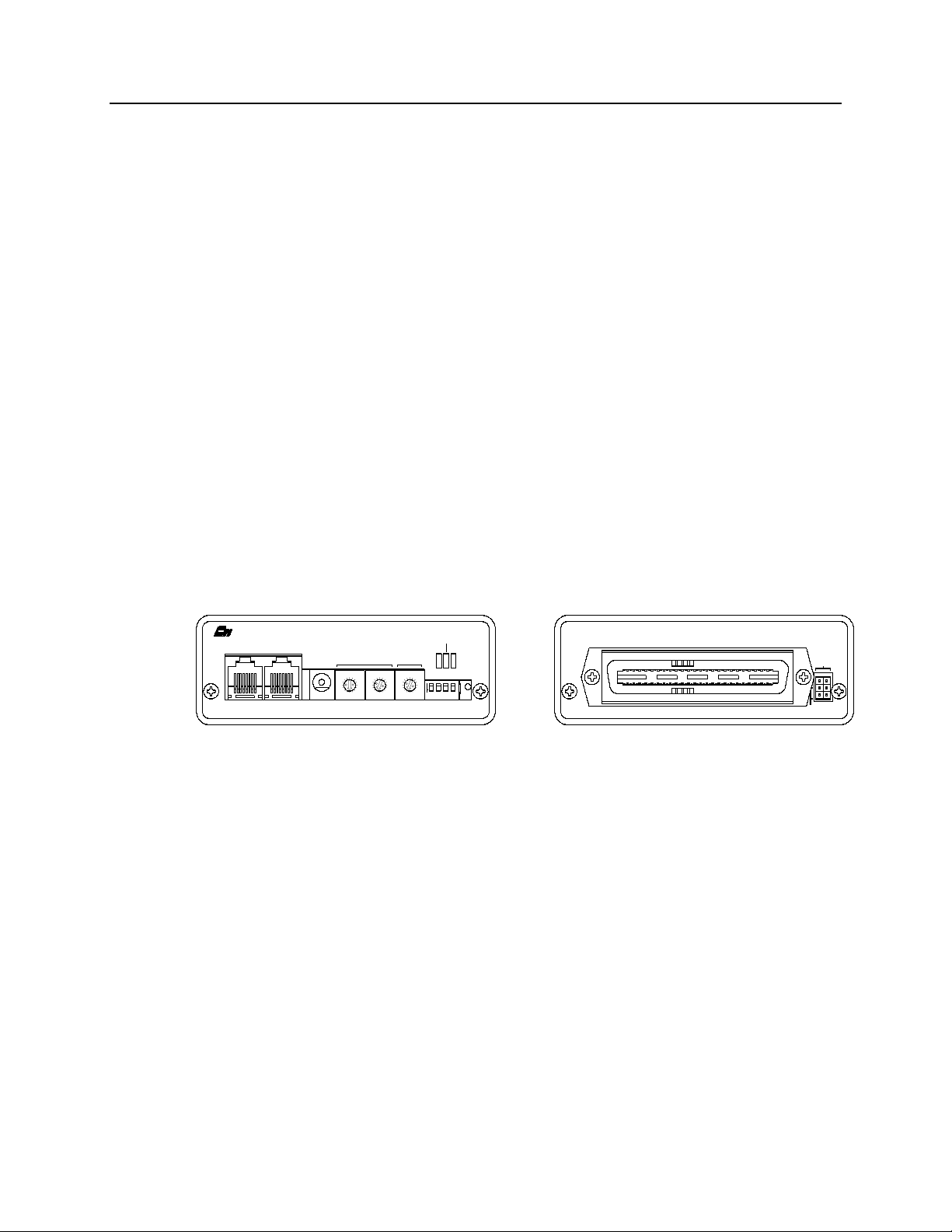
Figure 1 - CIB Front and Rear View
1.1 Reference Documents
1. Monitoring and Control Network System Manual
Part Number S2-60425
2. TSAM Interface Module (TIB) Hardware Reference Manual
Part Number S2-60469
RESET
E1 A
J1
E1 B
CA-80023-100
68-10854-135
1
Page 8
CIB Hardware Reference Specifications
CTI Products, Inc.
2. Specifications
Size 5.5” x 4.2” x 1.5”
(140 x 107 x 38 mm)
Weight 16 oz (455 gm)
Temperature 0 - 50 ºC
Humidity 10 - 95% non-condensing
Module Power 10 - 32 Vdc / 2 Watts max.
Number of Receivers Supported 8
Open Circuit Voltage (all I/O pins)
jumper E1B removed
jumper E1B installed
Inputs per Receiver
active low, pull-up to +5 or +15 Vdc
Input Voltage (Input and In/Out pins) -0.6 to 30 Vdc max
Input Current (Input and In/Out pins):
jumper E1B removed (Vin = 0 Vdc)
jumper E1B installed (Vin = 0 Vdc)
Outputs per Receiver (active low) Force Vote and Disable
Output Saturation Voltage (Outputs and
In/Out pins) with Iout = 100 mA
Output Pin Current (Outputs and In/Out
pins)
Maximum Power Dissipation 2 Watts
Input/Output Connection 50 pin Telco style
Network Connector (2) RJ-45 (1 in, 1 out)
Safety Approvals UL 1950
Emissions Compliance FCC Part 15, Class A
Susceptibility Compliance IEC 801-2
+15 Vdc nominal
+5 Vdc nominal
Vote, Receive, Disable and Fail
-720 µA max (source)
-270 µA max (source)
550 mV max.
150 mA max per pin (sink)
100 mA max per pin if all output are
ON
CSA 1950
EN 60950-1992
DOC Class A
EN55022
IEC 801-3
IEC 801-4
EN50082-1
Table 1 - Module Specifications
2
68-10854-135
Page 9
CIB Hardware Reference Specifications
CTI Products, Inc.
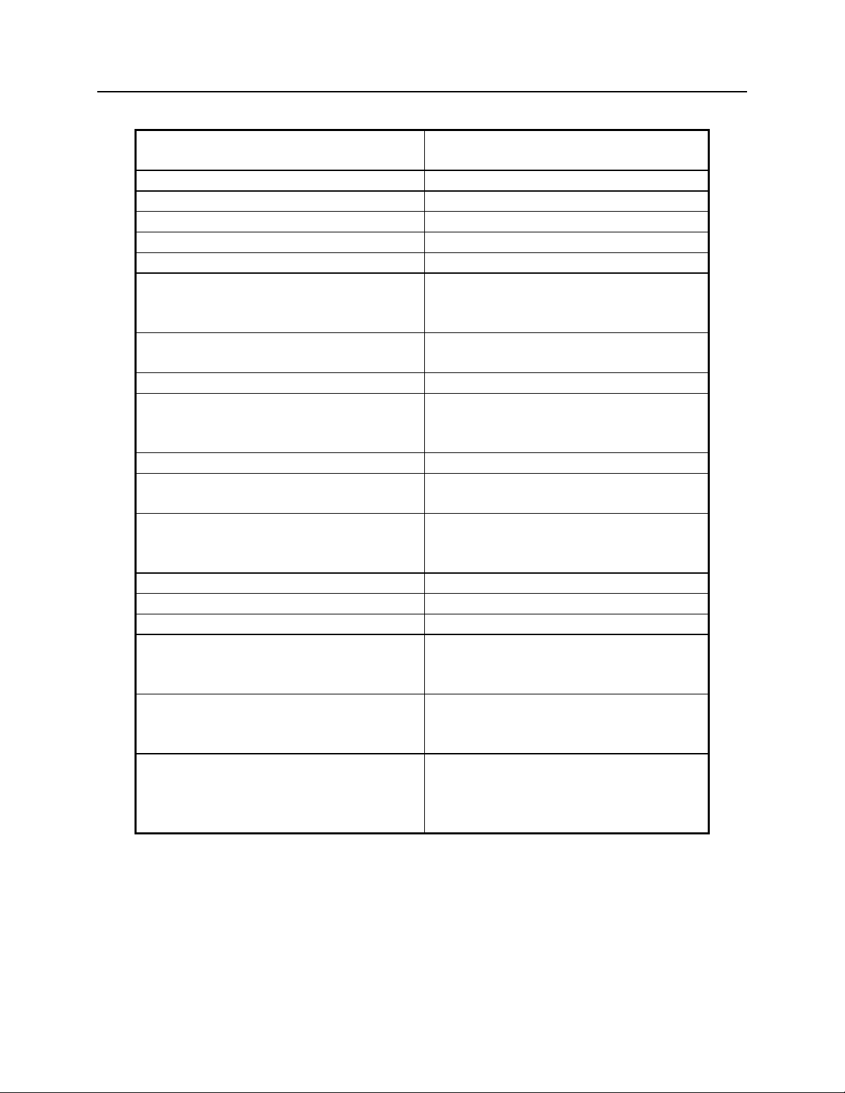
Figure 2 shows the equivalent circuits of the CIB I/O pins. The pull-up voltage
Vp by jumper E1B, located on the rear of the module.
Vp = 15 Vdc with jumper E1B out
•
Vp = 5.0 Vdc with jumper E1B in
•
HCMOS
IC
INPUT
+5V
+5V
150K
180K
INPUT
Vp
22K
0.01uF
Vp
22K
0.01uF
ESD
PROTECTION
ESD
PROTECTION
30V
TRANSORB
30V
TRANSORB
OUTPUT
Vp
22K
+5V
HCMOS
IC
INPUT
150K
0.01uF
INPUT/OUTPUT
Figure 2 - I/O Equivalent Circuit
3
ESD
PROTECTION
30V
TRANSORB
CA-80043-105
68-10854-135
Page 10
CIB Hardware Reference Theory of Operation
CTI Products, Inc.
3. Theory of Operation
This section describes the operation of the CIB module in an MCN comparator
display system.
3.1 Comparator Status
The CIB can accept VOTE, RECEIVE, DISABLE, and FAIL receiver status
indications from the comparator. Some comparators do not support all of these
status monitoring signals. Refer to section 7 for details about wiring the CIB to a
particular comparator. The CIB sends the status information to a User Interface
Module over the MCN network. User Interface Modules, such as the IIB (I/O
Interface Module) or HIB (Host Computer Interface Module) then display the
comparator status information on a console or PC.
3.2 Controlling the Comparator
When a User Interface Module sends FORCE VOTE or DISABLE commands, the
CIB translates the commands and activates the appropriate I/O lines of the
comparator.
The CIB updates the comparator with the latest control information whenever a
FORCE VOTE or DISABLE command is received from a User Interface Module.
3.3 System Example
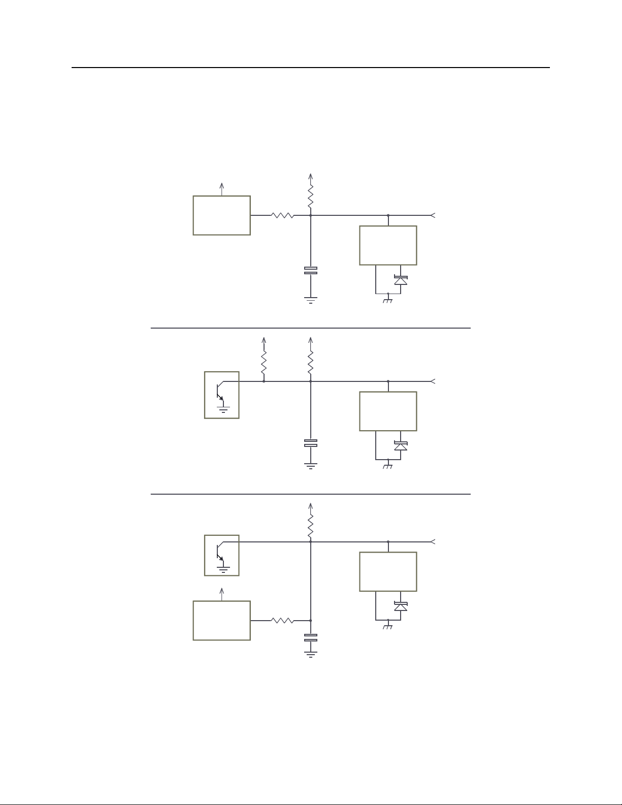
Figure 3 shows an example comparator display system using the CIB module.
OPERATOR
STATION
Figure 3 - CIB System Example
When the comparator detects that a receiver is active, it drives the RECEIVE
inputs to the CIB. If the receiver is also voted by the comparator, the comparator
drives the VOTE input as well. The CIB detects these inputs and sends receive
and vote messages to the User Interface Module. The User Interface Module then
indicates that the receiver is active and voted. If the User Interface Module is an
IIB, the IIB activates the VOTE and RX outputs for that receiver.
USER
INTERFACE
MODULE
MCN NETWORK
CIB
COMPARATOR
1
CA-80052-100
68-10854-135
4
Page 11

CIB Hardware Reference Theory of Operation
CTI Products, Inc.
If the comparator detects that a receiver has failed, then it drives the FAIL input to
the CIB. Again, the CIB detects this FAIL input and sends a message to the User
Interface Module so that the user can see that the receiver has failed.
From the operator station, the user can generate FORCE VOTE or DISABLE
commands for each receiver in the system. The User Interface Module detects
these commands and sends them to the CIB. The CIB then drives the appropriate
VOTE or DISABLE outputs to the comparator, telling it which receivers were
force voted or disabled.
3.4 Bi-directional I/O Signals
The CIB provides two input/output lines per receiver (VOTE and DISABLE) that
allow both monitoring and control of the signal (Figure 2 shows the equivalent
circuit for the input/output lines). If a receiver is disabled at the comparator, the
CIB will send a message to the User Interface Module so that the disabled
indication for the receiver can be shown at the operator station. Because the
comparator is now driving the input of the bi-directional DISABLE line, the
receiver cannot be re-enabled from the operator station. Pressing a disable button
on the operator station will have no affect on the receiver. If the disable button is
pressed multiple times, you could end up with the disable output latched on
(depending upon how many times the disable button is pressed). If this happens,
when the receiver is re-enabled at the comparator, the operator station will still
show the receiver being disabled when in fact the receiver is enabled. If you reenable a receiver at the comparator and the Disable indication remains on, reenable the receiver through the MCN system.
3.5 Transmitter Status Monitoring and Control
The MCN family includes an auxiliary module that allows monitoring and control
of transmitter sites. This module is called a TSAM Interface Module, or TIB, and
it interfaces between the CIB and CTI Product’s Transmitter Steering Audio
Matrix (TSAM) device (see reference 2). The CIB passes FORCE VOTE
information to the TIB to control or select the active transmitter. The TIB passes
transmitter information to the CIB so that the active transmitter can be displayed
with a User Interface Module that supports display of transmitter status, such as a
HIB with MCNRCD running on a PC.
The CIB will provide this transmitter monitoring and control only if its transmitter
monitoring enable switch, OPTION switch 3, is in the UP position. If this switch
is in the DOWN position, all transmitter monitoring and control is disabled.
The CIB and TIB communicate over the MCN network so no special wiring is
required between the modules.
5
68-10854-135
Page 12

CIB Hardware Reference Theory of Operation
CTI Products, Inc.
3.6 Operation With a Spectra-TAC Comparator
Some Motorola Spectra-TAC comparators with the "B" version Signal Quality
Module (SQM) can be damaged when a voltage greater than the comparator's
supply voltage is applied externally on the Disable input. (Motorola fixed this
problem in the "C" version SQM.) CIB modules shipped after January, 2003 are
shipped with E1B In, setting the input pull-up to +5 VDC.
Warning
Some "B" version SQM modules have a problem when they are inserted or
removed under power. Depending upon which pins connect first, the module may
be destroyed if there is an external connection to the Disable pin. The module
will try to power itself through the Disable pin and will destroy IC U3.
When inserting or removing the SQM from the comparator shelf, be sure to
first disable the module from the front panel switch on the SQM
assure that the Disable input is grounded. After the module is re-inserted, turn off
the Disable switch.
. This will
3.7 Operation With a Digitac Comparator
Installation Notes
A Digitac Comparator can be connected to a CIB module with a straight
•
through 50-pin cable. Jumper E1-A and E1 B must be out. See the CIB to
Digitac wiring chart. Be sure to set the Option Switches for Digitac
Comparator.
The switches and jumpers on the CIB module are difficult to reach after the
•
module is mounted to the comparator. Always set the switches and jumpers
for the CIB module before installing it on the back of the Digitac comparator.
Fail & Disable
The Motorola Digitac Comparator drives its Fail/Disable line low when:
A receiver input has failed (loss of status tone).
•
A receiver is disabled from the switch on the front panel of the comparator.
•
In either of these two cases, the MCNRCD software will display a “FAIL”
indication on the PC.
The MCNRCD software will display a “DISABLE” when the receiver site is
disabled from the PC, since the CIB is generating the Disable signal..
Coded Mode
The Digitac "Mode" (Coded) outputs appear on CIB "Fail" inputs. When you set
the CIB switches to Digitac mode, the CIB module ignores the Fail inputs. If the
switches are set improperly, you will see a "Fail" indication whenever the Digitac
receives a Coded transmission.
68-10854-135
6
Page 13

CIB Hardware Reference Theory of Operation
CTI Products, Inc.
3.8 Operation With a JPS SNV-12 Voter
The JPS SNV-12 voter has the following differences:
The front panel and RS-232 “DISABLE” signals are not brought to the rear
•
terminal block connector of the Voter modules.
The front panel and RS-232 “SELECT” signals are not brought to the rear
•
terminal block connector of the Voter modules.
Since these signals are not available to the CIB module, the MCNRCD software
will not display the front panel switch / RS-232 DISABLE and SELECT activity
for the SNV-12 voter card.
3.9 Operation With a Doug Hall 4RV/2 Voter
The DH 4RV-2 voter has opto-isolated inputs that allow the voter to work with
signals that go below ground (negative). These signals may be present when these
voters are used with positive ground equipment, such as microwaves. The CIB
module only functions properly with signal levels which are NOT below ground.
CAUTION
Do not operate a CIB module with any system that has signal levels
that go below ground level!
Damage to the CIB module can result and will void the warranty.
68-10854-135
7
Page 14

CIB Hardware Reference Option Switches
CTI Products, Inc.
4. Option Switches & Jumpers
Three sets of option switches are provided for module configuration. The module
must be power cycled or reset after these switches are set so that the options will
take effect. Table 2 describes the option switches and shows the factory defaults.
SWITCH DESCRIPTION DEFAULT
GROUP unit address setting (00-FE)
refer to the MCN System Manual
MODULE unit address setting (0-F)
refer to the MCN System Manual
OPTION
position 1
position 2 comparator selector 2 (see Table 3) DOWN
position 3 transmitter monitoring enable DOWN
position 4 force-vote timeout DOWN
comparator selector 1 (see Table 3) DOWN
Table 2 - CIB Option Switches
00
0
4.1 Group & Module Switches
The Group and Module selector switches are used to set the node address during
module installation. Refer to the Monitor and Control Network System Manual
for details about setting these switches.
4.2 Comparator Selector Switches
The comparator selector switches set the type of comparator the CIB is operating
with. Settings for these switches are shown in Table 3.
Comparator
Selector 1
SW 1
DOWN DOWN Spectra TAC
DOWN UP Digitac
UP DOWN TAC, G.E.,
UP UP other
Table 3 - Comparator Selector Switch Settings
If your specific comparator is not listed in Table 3, set both comparator selection
switches to the UP position for “other”. With this setting, the CIB will monitor
the VOTE, RECEIVE, DISABLE, and FAIL inputs from the comparator and pass
the status information to the display interface module. Also, the display interface
module can control the VOTE and DISABLE outputs of the CIB.
Comparator
Selector 2
SW 2
Comparator
Type
Selected
JPS SNV-12,
Doug Hall 4RV/2
68-10854-135
8
Page 15

CIB Hardware Reference Option Switches
CTI Products, Inc.
4.3 Transmitter Monitoring (TIB) Enable Switch
(CIB Versions 105 and greater)
The transmitter monitoring enable switch allows the CIB to operate with any
MCN family module that provides monitoring and control of transmitter steering,
such as the MCN TSAM Interface Module (TIB). Table 4 lists the functions and
positions of this switch. Refer to section 3.5 for more information about
transmitter status monitoring and control. If you enable the Transmitter
Monitoring feature, be sure to connect a TIB module which is properly addressed,
otherwise the CIB will have erratic operation.
Transmitter Monitoring
Switch SW3
UP Enabled
Down Disabled
Table 4 - Transmitter Monitoring Enable Switch
Transmitter Status
(TIB support)
4.4 Force-Vote Timeout Switch
(CIB Versions 110 and greater)
If you are using a dial-up connection to the MCN system and the modem
disconnects when you are force-voting a receiver, the CIB would not see the
“Release” message from the PC. This would force the system to continuously
vote the force-voted receiver.
The Force-Vote Timeout switch enables a 60-second timeout for all the ForceVote (Monitor) lines. This feature was added in CIB version 110. The 60-second
timeout is used to limit the time that a receiver may be force-voted. If you lose a
connection during a force-vote, the system will revert to normal in 60 seconds
maximum. It is recommended that this switch be UP to enable the timer in all
systems unless you need a continuous Force-Vote for longer than 60 seconds.
Force-Vote Timeout
Switch SW 4
DOWN Disabled
UP 60 Second Timeout
Table 5 - Force-Vote Timeout Switch Settings
Force-Vote Timeout
(No Timeout)
68-10854-135
9
Page 16

CIB Hardware Reference Option Switches
CTI Products, Inc.
4.5 Jumper Options
Figure 4 shows the configuration of the two jumper options available on the rear
of the CIB. These jumpers should be installed at system installation time with
power removed from the CIB.
E1 A
E1 B
CA-80024-100
Figure 4 - Jumper Options
Jumper E1A is located across the top 2 terminals of the 6 pin terminal block.
Jumper E1B is located across the left side middle and bottom terminals of the 6
pin terminal block. The remaining 2 terminals of the block are unused.
Jumper Function Default
E1A In to enable output MON 7.
Out to disable output MON 7. (For
Digitac only)
E1B In for inputs pulled up to +5 Vdc.
(Spectra-TAC w/ "B" SQMs)
Out for inputs pulled up to +15 Vdc.
Table 6 - Jumper Options Description
The MON7 line conflicts with a Digitac signal. Always remove E1A when using
the CIB with a Digitac comparator.
Some Spectra-TAC comparators with the "B" version Signal Quality Module
(SQM) can be damaged when 15V is applied externally on the Disable input. For
this reason, for CIB modules shipped after January, 2003 are shipped with E1B In,
setting the input pull-up to +5 VDC.
IN
IN
Remove the E1B jumper if your comparator requires +15 V pull-ups.
10
68-10854-135
Page 17

CIB Hardware Reference Connectors
CTI Products, Inc.
5. Connectors
The
NETWORK IN/OUT
CIB with other MCN modules. These ports carry both the network data signals as
well as DC power for power distribution with other modules. Table 7 gives the
pinout for these connectors. Figure 5 shows the location of pin 1 for each port.
PIN 1
ports on the front of the CIB are used to connect the
PRODUCTS, INC.
NETWORK
IN
OUT
DC IN
CA-80068-100
Figure 5 - Network IN/OUT Ports
Pin Function
1 DATA +
2 DATA 3+ POWER
4 No Connect
5 No Connect
6- POWER
7- POWER
8+ POWER
Table 7 - Network Connector Pinout
The
DC IN
distributed through the
NETWORK IN
port provides the primary power connection to the module. Power is
NETWORK OUT
connector to provide power to the
connector of the MCN unit it is connected to. Each power
supply can power up to four units total. See reference 1 for complete details of
connections to the network and DC IN connectors.
Connector J1 provides the discrete I/O for the receiver signals. Table 9 gives the
pinout for this connector. Table 8 describes the functions of the I/O signals.
11
68-10854-135
Page 18

CIB Hardware Reference Connectors
CTI Products, Inc.
Signal Direction Description
VOTE Input/Output Output activated to force vote a receiver.
Comparator grounds input to indicate a voted receiver.
RX Input Ground to indicate that a signal is being received.
DIS Input/Output Output activated to disable a receiver.
Ground input to indicate a disabled receiver.
FAIL Input Ground input to indicate a failed receiver.
MON Output Activated to force vote a receiver in the TAC and Ericsson /
G.E. comparators. Unused for all other comparators.
Table 8 - I/O Signal Descriptions
12
68-10854-135
Page 19

CIB Hardware Reference Connectors
CTI Products, Inc.
CIB Connector J1 Pinout in Logical Order
CIB J1 Function Direction Wire Color
21 Vote 1 Input/Output Blu/Vio
22 Rx 1 Input Org/Vio
20 Dis 1 Input/Output Slt/Yel
23 Fail 1 Input Grn/Vio
19 Mon 1 Output Brn/Yel
46 Vote 2 Input/Output Vio/Blu
47 Rx 2 Input Vio/Org
45 Dis 2 Input/Output Yel/Slt
48 Fail 2 Input Vio/Grn
44 Mon 2 Output Yel/Brn
15 Vote 3 Input/Output Slt/Blk
16 Rx 3 Input Blu/Yel
14 Dis 3 Input/Output Brn/Blk
17 Fail 3 Input Org/Yel
12 Mon 3 Output Org/Blk
40 Vote 4 Input/Output Blk/Slt
41 Rx 4 Input Yel/Blu
39 Dis 4 Input/Output Blk/Brn
42 Fail 4 Input Yel/Org
37 Mon 4 Output Blk/Org
9 Vote 5 Input/Output Brn/Red
10 Rx 5 Input Slt/Red
8 Dis 5 Input/Output Grn/Red
11 Fail 5 Input Blu/Blk
6 Mon 5 Output Blu/Red
34 Vote 6 Input/Output Red/Brn
35 Rx 6 Input Red/Slt
33 Dis 6 Input/Output Red/Grn
36 Fail 6 Input Blk/Blu
31 Mon 6 Output Red/Blu
3 Vote 7 Input/Output Grn/Wht
4 Rx 7 Input Brn/Wht
2 Dis 7 Input/Output Org/Wht
5 Fail 7 Input Slt/Wht
18 Mon 7 Output Grn/Yel
28 Vote 8 Input/Output Wht/Grn
29 Rx 8 Input Wht/Brn
27 Dis 8 Input/Output Wht/Org
30 Fail 8 Input Wht/Slt
26 Mon 8 Output Wht/Blu
1 Ground Blu/Wht
7 unused No Connect Org/Red
13 unused No Connect
24 unused No Connect
25 unused No Connect
32 unused No Connect
38 unused No Connect
43 unused No Connect
49 unused No Connect
50 unused No Connect
Table 9 - CIB Connector J1 Pinout in Logical Order
CIB Connector J1 Pinout in Punch-Block Order
13
68-10854-135
Page 20

CIB Hardware Reference Connectors
CTI Products, Inc.
CIB J1 Function Direction Wire Color
26 Mon 8 Output Wht/Blu
1 Ground Blu/Wht
27 Dis 8 Input/Output Wht/Org
2 Dis 7 Input/Output Org/Wht
28 Vote 8 Input/Output Wht/Grn
3 Vote 7 Input/Output Grn/Wht
29 Rx 8 Input Wht/Brn
4 Rx 7 Input Brn/Wht
30 Fail 8 Input Wht/Slt
5 Fail 7 Input Slt/Wht
31 Mon 6 Output Red/Blu
6 Mon 5 Output Blu/Red
32 unused No Connect
7 Unused No Connect Org/Red
33 Dis 6 Input/Output Red/Grn
8 Dis 5 Input/Output Grn/Red
34 Vote 6 Input/Output Red/Brn
9 Vote 5 Input/Output Brn/Red
35 Rx 6 Input Red/Slt
10 Rx 5 Input Slt/Red
36 Fail 6 Input Blk/Blu
11 Fail 5 Input Blu/Blk
37 Mon 4 Output Blk/Org
12 Mon 3 Output Org/Blk
38 unused No Connect
13 unused No Connect
39 Dis 4 Input/Output Blk/Brn
14 Dis 3 Input/Output Brn/Blk
40 Vote 4 Input/Output Blk/Slt
15 Vote 3 Input/Output Slt/Blk
41 Rx 4 Input Yel/Blu
16 Rx 3 Input Blu/Yel
42 Fail 4 Input Yel/Org
17 Fail 3 Input Org/Yel
43 unused No Connect
18 Mon 7 Output Grn/Yel
44 Mon 2 Output Yel/Brn
19 Mon 1 Output Brn/Yel
45 Dis 2 Input/Output Yel/Slt
20 Dis 1 Input/Output Slt/Yel
46 Vote 2 Input/Output Vio/Blu
21 Vote 1 Input/Output Blu/Vio
47 Rx 2 Input Vio/Org
22 Rx 1 Input Org/Vio
48 Fail 2 Input Vio/Grn
23 Fail 1 Input Grn/Vio
49 unused No Connect
24 unused No Connect
50 unused No Connect
25 unused No Connect
Table 10 - CIB Connector J1 Pinout in Punch Block Order
14
68-10854-135
Page 21

CIB Hardware Reference Mounting
CTI Products, Inc.
6. Mounting
Various mounting kits are available to mount the CIB module.
Mounting Kits
Rack Mount - 4 A size modules
1 Rack Unit (1.75") High
Rack Mount - 2 A size modules plus 1 B size module
1 Rack Unit (1.75") High
(Used to mount 2 CIBs and 1 EXB module.)
Wall Mount - 1 A size module S2-60444
Digitac Mounting Kit and Cable
Mounts on rear of Digitac comparator.
Includes "T" ribbon cable to connect to P805.
Refer the reference 1, section Mounting Options, for physical details about
mounting the CIB module.
S2-60435
S2-60443
S2-60437
CAUTION
Make sure that any mounting screws used to secure unit to a wall-mount bracket
or Digitac Bracket do not protrude into the unit’s enclosure more than 1/8 inches
from the bottom surface of the unit.
Using a larger screw that touches the PC board inside the unit may damage the
unit when it is powered. Doing so will void the unit’s warranty.
15
68-10854-135
Page 22

CIB Hardware Reference Mounting
CTI Products, Inc.
16
68-10854-135
Page 23

CIB Hardware Reference Comparator Wiring Lists
CTI Products, Inc.
7. Comparator Wiring Lists
This section includes wiring lists to help you connect a CIB module to a particular
comparator. If you are using a comparator not shown in this section, refer to
Table 9 for the pinout of connector J1 on the back of the CIB module.
NOTE
specified for jumpers E1A and E1B. Improper setting of these jumpers could
result in improper operation of your comparator display system.
Wiring lists are given for the following comparators:
The wiring lists tell you if the CIB J1 pin being connected is Input (I), Output (O)
or Input/Output (I/O). Refer to Figure 2 for a diagram of the CIB’s I/O circuitry.
Wiring lists are included for both Logical Order and Punch Block Order.
: When connecting the CIB to your comparator, please follow the settings
TAC page 18
•
Spectra TAC page 20
•
Digitac page 22
•
M/A-Com / Ericsson / G.E. Analog Voter page 24
•
JPS SNV-12 Voter page 27
•
Doug Hall 4RV/2 Voter page 30
•
17
68-10854-135
Page 24

CIB Hardware Reference Comparator Wiring Lists
CTI Products, Inc.
7.1 Motorola TAC Comparator
CIB
J1 I/O
21 I Blu/Vio Vote 1 16 Selected Chan
22 I Org/Vio Rx 1 5 Chan Receiving
20 I/O Slt/Yel Dis 1 18 Disable Input
23 I Grn/Vio Fail 1
19 O Brn/Yel Mon 1 17 Monitor Input
46 I Vio/Blu Vote 2 16 Selected Chan
47 I Vio/Org Rx 2 5 Chan Receiving
45 I/O Yel/Slt Dis 2 18 Disable Input
48 I Vio/Grn Fail 2
44 O Yel/Brn Mon 2 17 Monitor Input
15 I Slt/Blk Vote 3 16 Selected Chan
16 I Blu/Yel Rx 3 5 Chan Receiving
14 I/O Brn/Blk Dis 3 18 Disable Input
17 I Org/Yel Fail 3
12 O Org/Blk Mon 3 17 Monitor Input
40 I Blk/Slt Vote 4 16 Selected Chan
41 I Yel/Blu Rx 4 5 Chan Receiving
39 I/O Blk/Brn Dis 4 18 Disable Input
42 I Yel/Org Fail 4 --
37 O Blk/Org Mon 4 17 Monitor Input
9 I Brn/Red Vote 5 16 Selected Chan
10 I Slt/Red Rx 5 5 Chan Receiving
8 I/O Grn/Red Dis 5 18 Disable Input
11 I Blu/Blk Fail 5
6 O Blu/Red Mon 5 17 Monitor Input
34 I Red/Brn Vote 6 16 Selected Chan
35 I Red/Slt Rx 6 5 Chan Receiving
33 I/O Red/Grn Dis 6 18 Disable Input
36 I Blk/Blu Fail 6
31 O Red/Blu Mon 6 17 Monitor Input
3 I Grn/Wht Vote 7 16 Selected Chan
4 I Brn/Wht Rx 7 5 Chan Receiving
2 I/O Org/Wht Dis 7 18 Disable Input
5 I Slt/Wht Fail 7
18 O Grn/Yel Mon 7 17 Monitor Input
28 I Wht/Grn Vote 8 16 Selected Chan
29 I Wht/Brn Rx 8 5 Chan Receiving
27 I/O Wht/Org Dis 8 18 Disable Input
30 I Wht/Slt Fail 8
26 O Wht/Blu Mon 8 17 Monitor Input
1 Gnd Blu/Wht Ground 24 Ground
Wire
Color
RX Module
Function Pins TAC Signals Notes
Table 11 - CIB to TAC Wiring List - Logical Order
Jumpers: E1A IN E1B OUT
Option Switches: 1 UP 2 DOWN
18
68-10854-135
Page 25

CIB Hardware Reference Comparator Wiring Lists
CTI Products, Inc.
Motorola TAC Comparator
CIB
J1 I/O
26 O Wht/Blu Mon 8 17 Monitor Input
1 Gnd Blu/Wht Ground 24 Ground
27 I/O W ht/Org Dis 8 18 Disable Input
2 I/O Org/Wht Dis 7 18 Disable Input
28 I Wht/Grn Vote 8 16 Selected Chan
3 I Grn/Wht Vote 7 16 Selected Chan
29 I Wht/Brn Rx 8 5 Chan Receiving
4 I Brn/Wht Rx 7 5 Chan Receiving
30 I Wht/Slt Fail 8
5 I Slt/Wht Fail 7
31 O Red/Blu Mon 6 17 Monitor Input
6 O Blu/Red Mon 5 17 Monitor Input
32 Unused
7 Unused
33 I/O Red/Grn Dis 6 18 Disable Input
8 I/O Grn/Red Dis 5 18 Disable Input
34 I Red/Brn Vote 6 16 Selected Chan
9 I Brn/Red Vote 5 16 Selected Chan
35 I Red/Slt Rx 6 5 Chan Receiving
10 I Slt/Red Rx 5 5 Chan Receiving
36 I Blk/Blu Fail 6
11 I Blu/Blk Fail 5
37 O Blk/Org Mon 4 17 Monitor Input
12 O Org/Blk Mon 3 17 Monitor Input
38 Unused
13 Unused
39 I/O Blk/Brn Dis 4 18 Disable Input
14 I/O Brn/Blk Dis 3 18 Disable Input
40 I Blk/Slt Vote 4 16 Selected Chan
15 I Slt/Blk Vote 3 16 Selected Chan
41 I Yel/Blu Rx 4 5 Chan Receiving
16 I Blu/Yel Rx 3 5 Chan Receiving
42 I Yel/Org Fail 4 -17 I Org/Yel Fail 3
43 Unused
18 O Grn/Yel Mon 7 17 Monitor Input
44 O Yel/Brn Mon 2 17 Monitor Input
19 O Brn/Yel Mon 1 17 Monitor Input
45 I/O Yel/Slt Dis 2 18 Disable Input
20 I/O Slt/Yel Dis 1 18 Disable Input
46 I Vio/Blu Vote 2 16 Selected Chan
21 I Blu/Vio Vote 1 16 Selected Chan
47 I Vio/Org Rx 2 5 Chan Receiving
22 I Org/Vio Rx 1 5 Chan Receiving
48 I Vio/Grn Fail 2
23 I Grn/Vio Fail 1
49 Unused
24 Unused
50 Unused
25 Unused
Wire
Color
RX Module
Function Pins TAC Signals Notes
Table 12 - CIB to TAC Wiring List -Punch Block Order
Jumpers: E1A IN E1B OUT
Option Switches: 1 UP 2 DOWN
19
68-10854-135
Page 26

CIB Hardware Reference Comparator Wiring Lists
CTI Products, Inc.
7.2 Motorola Spectra TAC Comparator
CIB Wire Siq Qual Mod Spectra TAC
J1 I/O Color Function Pins Signal Notes
21 I/O Blu/Vio Vote/Mon 1 20 Vote Indicate
22 I Org/Vio Rx 1 11 Unsquelch Indicate
20 I/O Slt/Yel Dis 1 19 Module Disable
23 I Grn/Vio Fail 1 23 Failed Indicate
19 O Brn/Yel Mon 1
46 I/O Vio/Blu Vote/Mon 2 20 Vote Indicate
47 I Vio/Org Rx 2 11 Unsquelch Indicate
45 I/O Yel/Slt Dis 2 19 Module Disable
48 I Vio/Grn Fail 2 23 Failed Indicate
44 O Yel/Brn Mon 2
15 I/O Slt/Blk Vote/Mon 3 20 Vote Indicate
16 I Blu/Yel Rx 3 11 Unsquelch Indicate
14 I/O Brn/Blk Dis 3 19 Module Disable
17 I Org/Yel Fail 3 23 Failed Indicate
12 O Org/Blk Mon 3
40 I/O Blk/Slt Vote/Mon 4 20 Vote Indicate
41 I Yel/Blu Rx 4 11 Unsquelch Indicate
39 I/O Blk/Brn Dis 4 19 Module Disable
42 I Yel/Org Fail 4 23 Failed Indicate
37 O Blk/Org Mon 4
9 I/O Brn/Red Vote/Mon 5 20 Vote Indicate
10 I Slt/Red Rx 5 11 Unsquelch Indicate
8 I/O Grn/Red Dis 5 19 Module Disable
11 I Blu/Blk Fail 5 23 Failed Indicate
6 O Blu/Red Mon 5
34 I/O Red/Brn Vote/Mon 6 20 Vote Indicate
35 I Red/Slt Rx 6 11 Unsquelch Indicate
33 I/O Red/Grn Dis 6 19 Module Disable
36 I Blk/Blu Fail 6 23 Failed Indicate
31 O Red/Blu Mon 6
3 I/O Grn/Wht Vote/Mon 7 20 Vote Indicate
4 I Brn/Wht Rx 7 11 Unsquelch Indicate
2 I/O Org/Wht Dis 7 19 Module Disable
5 I Slt/Wht Fail 7 23 Failed Indicate
18 O Grn/Yel Mon 7
28 I/O Wht/Grn Vote/Mon 8 20 Vote Indicate
29 I Wht/Brn Rx 8 11 Unsquelch Indicate
27 I/O Wht/Org Dis 8 19 Module Disable
30 I Wht/Slt Fail 8 23 Failed Indicate
26 O Wht/Blu Mon 8
1 Gnd Blu/Wht Ground 1 Ground
Table 13 - CIB to Spectra-TAC Wiring List - Logical Order
Jumpers: E1A IN E1B IN
Option Switches: 1 DOWN 2 DOWN
20
68-10854-135
Page 27

CIB Hardware Reference Comparator Wiring Lists
CTI Products, Inc.
Motorola Spectra TAC Comparator
CIB Wire Siq Qual Mod Spectra TAC
J1 I/O Color Function Pins Signal Notes
26 O Wht/Blu Mon 8
1 Gnd Blu/Wht Ground 1 Ground
27 I/O Wht/Org Dis 8 19 Module Disable
2 I/O Org/Wht Dis 7 19 Module Disable
28 I/O Wht/Grn Vote/Mon 8 20 Vote Indicate
3 I/O Grn/Wht Vote/Mon 7 20 Vote Indicate
29 I Wht/Brn Rx 8 11 Unsquelch Indicate
4 I Brn/Wht Rx 7 11 Unsquelch Indicate
30 I Wht/Slt Fail 8 23 Failed Indicate
5 I Slt/Wht Fail 7 23 Failed Indicate
31 O Red/Blu Mon 6
6 O Blu/Red Mon 5
32 Unused
7 Unused
33 I/O Red/Grn Dis 6 19 Module Disable
8 I/O Grn/Red Dis 5 19 Module Disable
34 I/O Red/Brn Vote/Mon 6 20 Vote Indicate
9 I/O Brn/Red Vote/Mon 5 20 Vote Indicate
35 I Red/Slt Rx 6 11 Unsquelch Indicate
10 I Slt/Red Rx 5 11 Unsquelch Indicate
36 I Blk/Blu Fail 6 23 Failed Indicate
11 I Blu/Blk Fail 5 23 Failed Indicate
37 O Blk/Org Mon 4
12 O Org/Blk Mon 3
38 Unused
13 Unused
39 I/O Blk/Brn Dis 4 19 Module Disable
14 I/O Brn/Blk Dis 3 19 Module Disable
40 I/O Blk/Slt Vote/Mon 4 20 Vote Indicate
15 I/O Slt/Blk Vote/Mon 3 20 Vote Indicate
41 I Yel/Blu Rx 4 11 Unsquelch Indicate
16 I Blu/Yel Rx 3 11 Unsquelch Indicate
42 I Yel/Org Fail 4 23 Failed Indicate
17 I Org/Yel Fail 3 23 Failed Indicate
43 Unused
18 O Grn/Yel Mon 7
44 O Yel/Brn Mon 2
19 O Brn/Yel Mon 1
45 I/O Yel/Slt Dis 2 19 Module Disable
20 I/O Slt/Yel Dis 1 19 Module Disable
46 I/O Vio/Blu Vote/Mon 2 20 Vote Indicate
21 I/O Blu/Vio Vote/Mon 1 20 Vote Indicate
47 I Vio/Org Rx 2 11 Unsquelch Indicate
22 I Org/Vio Rx 1 11 Unsquelch Indicate
48 I Vio/Grn Fail 2 23 Failed Indicate
23 I Grn/Vio Fail 1 23 Failed Indicate
49 Unused
24 Unused
50 Unused
25 Unused
Table 14 - CIB to Spectra-TAC Wiring List - Punch Block Order
Jumpers: E1A IN E1B IN
Option Switches: 1 DOWN 2 DOWN
21
68-10854-135
Page 28

CIB Hardware Reference Comparator Wiring Lists
CTI Products, Inc.
7.3 Motorola Digitac Comparator
CIB
J1 I/O
21 I/O Blu/Vio Vote 1 21 Vote/Mon 1
22 I Org/Vio Rx 1 22 Active Chan 1
20 I/O Slt/Yel Dis 1 20 Fail/Disable 1
23 I Grn/Vio Fail 1 23 * Mode Chan 1
19 O Brn/Yel Mon 1 19 *
46 I Vio/Blu Vote 2 46 Vote/Mon 2
47 I Vio/Org Rx 2 47 Active Chan 2
45 I/O Yel/Slt Dis 2 45 Fail/Disable 2
48 I Vio/Grn Fail 2 48 * Mode Chan 2
44 O Yel/Brn Mon 2 44 *
15 I Slt/Blk Vote 3 15 Vote/Mon 3
16 I Blu/Yel Rx 3 16 Active Chan 3
14 I/O Brn/Blk Dis 3 14 Fail/Disable 3
17 I Org/Yel Fail 3 17 * Mode Chan 3
12 O Org/Blk Mon 3 12 *
40 I Blk/Slt Vote 4 40 Vote/Mon 4
41 I Yel/Blu Rx 4 41 Active Chan 4
39 I/O Blk/Brn Dis 4 39 Fail/Disable 4
42 I Yel/Org Fail 4 42 * Mode Chan 4
37 O Blk/Org Mon 4 37 *
9 I Brn/Red Vote 5 9 Vote/Mon 5
10 I Slt/Red Rx 5 10 Active Chan 5
8 I/O Grn/Red Dis 5 8 Fail/Disable 5
11 I Blu/Blk Fail 5 11 * Mode Chan 5
6 O Blu/Red Mon 5 6 *
34 I Red/Brn Vote 6 34 Vote/Mon 6
35 I Red/Slt Rx 6 35 Active Chan 6
33 I/O Red/Grn Dis 6 33 Fail/Disable 6
36 I Blk/Blu Fail 6 36 * Mode Chan 6
31 O Red/Blu Mon 6 31 *
3 I Grn/Wht Vote 7 3 Vote/Mon 7
4 I Brn/Wht Rx 7 4 Active Chan 7
2 I/O Org/Wht Dis 7 2 Fail/Disable 7
5 I Slt/Wht Fail 7 5 * Mode Chan 7
18 O Grn/Yel Mon 7 18 *
28 I Wht/Grn Vote 8 28 Vote/Mon 8
29 I Wht/Brn Rx 8 29 Active Chan 8
27 I/O Wht/Org Dis 8 27 Fail/Disable 8
30 I Wht/Slt Fail 8 30 * Mode Chan 8
26 O Wht/Blu Mon 8 26 *
1 Gnd Blu/Wht Ground 1 Ground
Wire
Color
P805 Pins Digitac
Function Signals Notes
E1-A must be removed to isolate this signal.
Table 15 - CIB to Digitac Wiring List - Logical Order
Jumpers: E1A OUT E1B OUT
Option Switches: 1 DOWN 2 UP
* These pins are not used by the CIB when configured for the Digitac comparator and will not
conflict with Digitac operation when connected to P805 with a 50 pin straight through cable
68-10854-135
22
Page 29

CIB Hardware Reference Comparator Wiring Lists
CTI Products, Inc.
Motorola Digitac Comparator
CIB
J1 I/O
26 O Wht/Blu Mon 8 26 *
1 Gnd Blu/Wht Ground 1 Ground
27 I/O Wht/Org Dis 8 27 Fail/Disable 8
2 I/O Org/Wht Dis 7 2 Fail/Disable 7
28 I Wht/Grn Vote 8 28 Vote/Mon 8
3 I Grn/Wht Vote 7 3 Vote/Mon 7
29 I Wht/Brn Rx 8 29 Active Chan 8
4 I Brn/Wht Rx 7 4 Active Chan 7
30 I Wht/Slt Fail 8 30 * Mode Chan 8
5 I Slt/Wht Fail 7 5 * Mode Chan 7
31 O Red/Blu Mon 6 31 *
6 O Blu/Red Mon 5 6 *
32 Unused
7 Unused
33 I/O Red/Grn Dis 6 33 Fail/Disable 6
8 I/O Grn/Red Dis 5 8 Fail/Disable 5
34 I Red/Brn Vote 6 34 Vote/Mon 6
9 I Brn/Red Vote 5 9 Vote/Mon 5
35 I Red/Slt Rx 6 35 Active Chan 6
10 I Slt/Red Rx 5 10 Active Chan 5
36 I Blk/Blu Fail 6 36 * Mode Chan 6
11 I Blu/Blk Fail 5 11 * Mode Chan 5
37 O Blk/Org Mon 4 37 *
12 O Org/Blk Mon 3 12 *
38 Unused
13 Unused
39 I/O Blk/Brn Dis 4 39 Fail/Disable 4
14 I/O Brn/Blk Dis 3 14 Fail/Disable 3
40 I Blk/Slt Vote 4 40 Vote/Mon 4
15 I Slt/Blk Vote 3 15 Vote/Mon 3
41 I Yel/Blu Rx 4 41 Active Chan 4
16 I Blu/Yel Rx 3 16 Active Chan 3
42 I Yel/Org Fail 4 42 * Mode Chan 4
17 I Org/Yel Fail 3 17 * Mode Chan 3
43 Unused
18 O Grn/Yel Mon 7 18 *
44 O Yel/Brn Mon 2 44 *
19 O Brn/Yel Mon 1 19 *
45 I/O Yel/Slt Dis 2 45 Fail/Disable 2
20 I/O Slt/Yel Dis 1 20 Fail/Disable 1
46 I Vio/Blu Vote 2 46 Vote/Mon 2
21 I/O Blu/Vio Vote 1 21 Vote/Mon 1
47 I Vio/Org Rx 2 47 Active Chan 2
22 I Org/Vio Rx 1 22 Active Chan 1
48 I Vio/Grn Fail 2 48 * Mode Chan 2
23 I Grn/Vio Fail 1 23 * Mode Chan 1
49 Unused
24 Unused
50 Unused
25 Unused
Wire
Color
P805 Pins Digitac
Function Signals Notes
E1-A must be removed to isolate this signal
Table 16 - CIB to Digitac Wiring List - Punch Block Order
Jumpers: E1A OUT E1B OUT
Option Switches: 1 DOWN 2 UP
* These pins are not used by the CIB when configured for the Digitac comparator and will not
conflict with Digitac operation when connected to P805 with a 50 pin straight through cable
68-10854-135
23
Page 30

CIB Hardware Reference Comparator Wiring Lists
CTI Products, Inc.
7.4 M/A-Com / Ericsson / G.E. Analog Voter
Wire
P1 I/O
21 I Blu/Vio Vote 1 TB ___ Pin 4 SELECT
22 I Org/Vio Rx 1 TB ___ Pin 6 UNSQ
20 I/O Slt/Yel Dis 1 TB ___ Pin 1 REJ SW
23 I Grn/Vio Fail 1 RX Mod Pin 19 * FAIL *
19 O Brn/Yel Mon 1 TB ___ Pin 2 SEL SW
46 I Vio/Blu Vote 2 TB ___ Pin 4 SELECT
47 I Vio/Org Rx 2 TB ___ Pin 6 UNSQ
45 I/O Yel/Slt Dis 2 TB ___ Pin 1 REJ SW
48 I Vio/Grn Fail 2 RX Mod Pin 19 * FAIL *
44 O Yel/Brn Mon 2 TB ___ Pin 2 SEL SW
15 I Slt/Blk Vote 3 TB ___ Pin 4 SELECT
16 I Blu/Yel Rx 3 TB ___ Pin 6 UNSQ
14 I/O Brn/Blk Dis 3 TB ___ Pin 1 REJ SW
17 I Org/Yel Fail 3 RX Mod Pin 19 * FAIL *
12 O Org/Blk Mon 3 TB ___ Pin 2 SEL SW
40 I Blk/Slt Vote 4 TB ___ Pin 4 SELECT
41 I Yel/Blu Rx 4 TB ___ Pin 6 UNSQ
39 I/O Blk/Brn Dis 4 TB ___ Pin 1 REJ SW
42 I Yel/Org Fail 4 RX Mod Pin 19 * FAIL *
37 O Blk/Org Mon 4 TB ___ Pin 2 SEL SW
9 I Brn/Red Vote 5 TB ___ Pin 4 SELECT
10 I Slt/Red Rx 5 TB ___ Pin 6 UNSQ
8 I/O Grn/Red Dis 5 TB ___ Pin 1 REJ SW
11 I Blu/Blk Fail 5 RX Mod Pin 19 * FAIL *
6 O Blu/Red Mon 5 TB ___ Pin 2 SEL SW
34 I Red/Brn Vote 6 TB ___ Pin 4 SELECT
35 I Red/Slt Rx 6 TB ___ Pin 6 UNSQ
33 I/O Red/Grn Dis 6 TB ___ Pin 1 REJ SW
36 I Blk/Blu Fail 6 RX Mod Pin 19 * FAIL *
31 O Red/Blu Mon 6 TB ___ Pin 2 SEL SW
3 I Grn/Wht Vote 7 TB ___ Pin 4 SELECT
4 I Brn/Wht Rx 7 TB ___ Pin 6 UNSQ
2 I/O Org/Wht Dis 7 TB ___ Pin 1 REJ SW
5 I Slt/Wht Fail 7 RX Mod Pin 19 * FAIL *
18 O Grn/Yel Mon 7 TB ___ Pin 2 SEL SW
28 I Wht/Grn Vote 8 TB ___ Pin 4 SELECT
29 I Wht/Brn Rx 8 TB ___ Pin 6 UNSQ
27 I/O Wht/Org Dis 8 TB ___ Pin 1 REJ SW
30 I W ht/Slt Fail 8 RX Mod Pin 19 * FAIL *
26 O Wht/Blu Mon 8 TB ___ Pin 2 SEL SW
1 Gnd Blu/Wht Ground RX Mod Pin F/6 GRD
Color
Function RX Mod Pins Name Notes
TB1-TB6 or GE Sig.
Table 17 - CIB to M/A-Com / Ericsson / G.E. Analog Voter - Logical Order
Jumpers: E1A IN E1B OUT
Option Switches: 1 UP 2 DOWN
* See section 7.4.1 for a description of the receiver module modifications needed to
monitor the fail signal.
68-10854-135
24
Page 31

CIB Hardware Reference Comparator Wiring Lists
CTI Products, Inc.
M/A-Com / Ericsson / G.E. Analog Voter
Wire
P1 I/O
26 O Wht/Blu Mon 8 TB ___ Pin 2 SEL SW
1 Gnd Blu/Wht Ground RX Mod Pin F/6 GRD
27 I/O Wht/Org Dis 8 TB ___ Pin 1 REJ SW
2 I/O Org/Wht Dis 7 TB ___ Pin 1 REJ SW
28 I Wht/Grn Vote 8 TB ___ Pin 4 SELECT
3 I Grn/Wht Vote 7 TB ___ Pin 4 SELECT
29 I Wht/Brn Rx 8 TB ___ Pin 6 UNSQ
4 I Brn/Wht Rx 7 TB ___ Pin 6 UNSQ
30 I W ht/Slt Fail 8 RX Mod Pin 19 * FAIL *
5 I Slt/Wht Fail 7 RX Mod Pin 19 * FAIL *
31 O Red/Blu Mon 6 TB ___ Pin 2 SEL SW
6 O Blu/Red Mon 5 TB ___ Pin 2 SEL SW
32 Unused
7 Unused
33 I/O Red/Grn Dis 6 TB ___ Pin 1 REJ SW
8 I/O Grn/Red Dis 5 TB ___ Pin 1 REJ SW
34 I Red/Brn Vote 6 TB ___ Pin 4 SELECT
9 I Brn/Red Vote 5 TB ___ Pin 4 SELECT
35 I Red/Slt Rx 6 TB ___ Pin 6 UNSQ
10 I Slt/Red Rx 5 TB ___ Pin 6 UNSQ
36 I Blk/Blu Fail 6 RX Mod Pin 19 * FAIL *
11 I Blu/Blk Fail 5 RX Mod Pin 19 * FAIL *
37 O Blk/Org Mon 4 TB ___ Pin 2 SEL SW
12 O Org/Blk Mon 3 TB ___ Pin 2 SEL SW
38 Unused
13 Unused
39 I/O Blk/Brn Dis 4 TB ___ Pin 1 REJ SW
14 I/O Brn/Blk Dis 3 TB ___ Pin 1 REJ SW
40 I Blk/Slt Vote 4 TB ___ Pin 4 SELECT
15 I Slt/Blk Vote 3 TB ___ Pin 4 SELECT
41 I Yel/Blu Rx 4 TB ___ Pin 6 UNSQ
16 I Blu/Yel Rx 3 TB ___ Pin 6 UNSQ
42 I Yel/Org Fail 4 RX Mod Pin 19 * FAIL *
17 I Org/Yel Fail 3 RX Mod Pin 19 * FAIL *
43 Unused
18 O Grn/Yel Mon 7 TB ___ Pin 2 SEL SW
44 O Yel/Brn Mon 2 TB ___ Pin 2 SEL SW
19 O Brn/Yel Mon 1 TB ___ Pin 2 SEL SW
45 I/O Yel/Slt Dis 2 TB ___ Pin 1 REJ SW
20 I/O Slt/Yel Dis 1 TB ___ Pin 1 REJ SW
46 I Vio/Blu Vote 2 TB ___ Pin 4 SELECT
21 I Blu/Vio Vote 1 TB ___ Pin 4 SELECT
47 I Vio/Org Rx 2 TB ___ Pin 6 UNSQ
22 I Org/Vio Rx 1 TB ___ Pin 6 UNSQ
48 I Vio/Grn Fail 2 RX Mod Pin 19 * FAIL *
23 I Grn/Vio Fail 1 RX Mod Pin 19 * FAIL *
49 Unused
24 Unused
50 Unused
25 Unused
Color
Function RX Mod Pins Name Notes
TB1-TB6 or GE Sig.
Table 18 - CIB to M/A-Com / Ericsson / G.E. Analog Voter - Punch Block Order
Jumpers: E1A IN E1B OUT
Option Switches: 1 UP 2 DOWN
* See next section for description of modifications needed to monitor the fail signal.
68-10854-135
25
Page 32

CIB Hardware Reference Comparator Wiring Lists
CTI Products, Inc.
7.4.1
Voter Modifications For Receiver Module Fail Monitoring
There is no isolated Fail signal brought out on the G.E. receiver module. The Fail
signal on all modules are bussed together to provide a single Fail signal on the
voter backplane. A field modification is required to bring out an isolated Fail line
for each of the receiver modules. There are two ways to modify the voter to
provide the isolated Fail signals: the Backplane modification and the Receiver
Module modification.
7.4.1.1
7.4.1.2
Backplane Modification
The backplane modification is the easiest modification. It will work with either
the old or new style receiver mosules. If you do not have a need for a common
Fail output, you can cut the trace that ties together all the Fail/Alarm outputs on
the receiver modules.
To do this, use a Dremel Tool or an Exacto knife to cut the trace on the backplane
between pins 5/E on all the receiver modules. Connect the Fail line from the CIIB
to pin 5/E on each module by soldering it to the backplane
Receiver Module Modification
If you do need a common Fail/Alarm line, and you want to display the Fail
indication through the CIB module, you will have to modify each receiver
module. The S3-60355 GE Receiver Module Fail Line Kit includes a diode and
wires that are used to bring out the individual Fail line. Install one modification
kit for each receiver module.
Modification for Old Style Receiver Modules
The old receiver modules (19D413994G1) are transistorized and don’t have ICs.
Add a modification kit on each receiver module. Connect the black wire
(cathode) to the collector of Q40. Connect the red wire (anode) to pin 19 of the
edge connector. This may be done on the solder side of the board. Please note
that the wires on the diodes in the modification kit are furnished long because the
kit is intended for use with 2 types of modules. Cut each of the wires to the
proper length for a neat installation.
Modification for New Style Receiver Modules
The new receiver modules (19D903175G1) use ICs. Add a modification kit on
each receiver module. Connect the black wire (cathode) to the cathode of DS1
(collector of Q7). Connect the red wire (anode) to pin 19 of the edge connector.
This may be done on the solder side of the board. Please note that the wires on
the diodes in the modification kit are furnished long because the kit is intended for
use with 2 types of modules. Cut each of the wires to the proper length for a neat
installation.
68-10854-135
26
Page 33

CIB Hardware Reference Comparator Wiring Lists
CTI Products, Inc.
7.5 JPS SNV-12 Voter
CIB Wire Site/Voter Voter Module Voter Module
J1 I/O Color Function Module Terminals Signal Notes
21 I Blu/Vio Vote 1 1 / TB1 15 Voted Out
22 I Org/Vio Rx 1 1 / TB1 16 Unsquelch Out
20 O Slt/Yel Dis 1 1 / TB1 12 Disable In
23 I Grn/Vio Fail 1 1 / TB1 17 Fault Out
19 O Brn/Yel Mon 1 1 / TB1 11 Select In
46 I Vio/Blu Vote 2 2 / TB2 15 Voted Out
47 I Vio/Org Rx 2 2 / TB2 16 Unsquelch Out
45 O Yel/Slt Dis 2 2 / TB2 12 Disable In
48 I Vio/Grn Fail 2 2 / TB2 17 Fault Out
44 O Yel/Brn Mon 2 2 / TB2 11 Select In
15 I Slt/Blk Vote 3 3 / TB3 15 Voted Out
16 I Blu/Yel Rx 3 3 / TB3 16 Unsquelch Out
14 O Brn/Blk Dis 3 3 / TB3 12 Disable In
17 I Org/Yel Fail 3 3 / TB3 17 Fault Out
12 O Org/Blk Mon 3 3 / TB3 11 Select In
40 I Blk/Slt Vote 4 4 / TB4 15 Voted Out
41 I Yel/Blu Rx 4 4 / TB4 16 Unsquelch Out
39 O Blk/Brn Dis 4 4 / TB4 12 Disable In
42 I Yel/Org Fail 4 4 / TB4 17 Fault Out
37 O Blk/Org Mon 4 4 / TB4 11 Select In
9 I Brn/Red Vote 5 5 / TB5 15 Voted Out
10 I Slt/Red Rx 5 5 / TB5 16 Unsquelch Out
8 O Grn/Red Dis 5 5 / TB5 12 Disable In
11 I Blu/Blk Fail 5 5 / TB5 17 Fault Out
6 O Blu/Red Mon 5 5 / TB5 11 Select In
34 I Red/Brn Vote 6 6 / TB6 15 Voted Out
35 I Red/Slt Rx 6 6 / TB6 16 Unsquelch Out
33 O Red/Grn Dis 6 6 / TB6 12 Disable In
36 I Blk/Blu Fail 6 6 / TB6 17 Fault Out
31 O Red/Blu Mon 6 6 / TB6 11 Select In
3 I Grn/Wht Vote 7 7 / TB7 15 Voted Out
4 I Brn/Wht Rx 7 7 / TB7 16 Unsquelch Out
2 O Org/Wht Dis 7 7 / TB7 12 Disable In
5 I Slt/Wht Fail 7 7 / TB7 17 Fault Out
18 O Grn/Yel Mon 7 7 / TB7 11 Select In
28 I Wht/Grn Vote 8 8 / TB8 15 Voted Out
29 I Wht/Brn Rx 8 8 / TB8 16 Unsquelch Out
27 O Wht/Org Dis 8 8 / TB8 12 Disable In
30 I Wht/Slt Fail 8 8 / TB8 17 Fault Out
26 O Wht/Blu Mon 8 8 / TB8 11 Select In
1 Gnd Blu/Wht Ground Any 20 Ground
Table 19 - CIB to JPS SNV-12 Voter Wiring List - Logical Order
Jumpers: E1A IN E1B OUT
Option Switches: 1 UP 2 DOWN
27
68-10854-135
Page 34

CIB Hardware Reference Comparator Wiring Lists
CTI Products, Inc.
JPS SNV-12 Voter
CIB Wire Site/Voter Voter Module Voter Module
J1 I/O Color Function Module Terminals Signal Notes
26 O Wht/Blu Mon 8 8 / TB 8 11 Select In
1 Gnd Blu/Wht Ground Any 20 Ground
27 O Wht/Org Dis 8 8 / TB 8 12 Disable In
2 O Org/Wht Dis 7 7 / TB 7 12 Disable In
28 I Wht/Grn Vote 8 8 / TB 8 15 Voted Out Site Voter Module 8 (TB 8)
3 I Grn/Wht Vote 7 7 / TB 7 15 Voted Out Site Voter Module 7 (TB 7)
29 I Wht/Brn Rx 8 8 / TB 8 16 Unsquelch Out
4 I Brn/Wht Rx 7 7 / TB 7 16 Unsquelch Out
30 I Wht/Slt Fail 8 8 / TB 8 17 Fault Out
5 I Slt/Wht Fail 7 7 / TB 7 17 Fault Out
31 O Red/Blu Mon 6 6 / TB 6 11 Select In
6 O Blu/Red Mon 5 5 / TB 5 11 Select In
32 Unused
7 Unused
33 O Red/Grn Dis 6 6 / TB 6 12 Disable In
8 O Grn/Red Dis 5 5 / TB 5 12 Disable In
34 I Red/Brn Vote 6 6 / TB 6 15 Voted Out Site Voter Module 6 (TB 6)
9 I Brn/Red Vote 5 5 / TB 5 15 Voted Out Site Voter Module 5 (TB 5)
35 I Red/Slt Rx 6 6 / TB 6 16 Unsquelch Out
10 I Slt/Red Rx 5 5 / TB 5 16 Unsquelch Out
36 I Blk/Blu Fail 6 6 / TB 6 17 Fault Out
11 I Blu/Blk Fail 5 5 / TB 5 17 Fault Out
37 O Blk/Org Mon 4 4 / TB 4 11 Select In
12 O Org/Blk Mon 3 3 / TB 3 11 Select In
38 Unused
13 Unused
39 O Blk/Brn Dis 4 4 / TB 4 12 Disable In
14 O Brn/Blk Dis 3 3 / TB 3 12 Disable In
40 I Blk/Slt Vote 4 4 / TB 4 15 Voted Out Site Voter Module 4 (TB 4)
15 I Slt/Blk Vote 3 3 / TB 3 15 Voted Out Site Voter Module 3 (TB 3)
41 I Yel/Blu Rx 4 4 / TB 4 16 Unsquelch Out
16 I Blu/Yel Rx 3 3 / TB 3 16 Unsquelch Out
42 I Yel/Org Fail 4 4 / TB 4 17 Fault Out
17 I Org/Yel Fail 3 3 / TB 3 17 Fault Out
43 Unused
18 O Grn/Yel Mon 7 7 / TB 7 11 Select In
44 O Yel/Brn Mon 2 2 / TB 2 11 Select In
19 O Brn/Yel Mon 1 1 / TB 1 11 Select In
45 O Yel/Slt Dis 2 2 / TB 2 12 Disable In
20 O Slt/Yel Dis 1 1 / TB 1 12 Disable In
46 I Vio/Blu Vote 2 2 / TB 2 15 Voted Out Site Voter Module 2 (TB 2)
21 I Blu/Vio Vote 1 1 / TB 1 15 Voted Out Site Voter Module 1 (TB 1)
47 I Vio/Org Rx 2 2 / TB 2 16 Unsquelch Out
22 I Org/Vio Rx 1 1 / TB 1 16 Unsquelch Out
48 I Vio/Grn Fail 2 2 / TB 2 17 Fault Out
23 I Grn/Vio Fail 1 1 / TB 1 17 Fault Out
49 Unused
24 Unused
50 Unused
25 Unused
Table 20 - CIB to JPS SNV-12 Voter Wiring List - Punch Block Order
Jumpers: E1A IN E1B OUT
Option Switches: 1 UP 2 DOWN
28
68-10854-135
Page 35

CIB Hardware Reference Comparator Wiring Lists
CTI Products, Inc.
7.5.1
JPS Voter Modifications for Monitoring Voted Out using Channel Select In
The JPS SNV-12 Voters with firmware version 1.08 or lower do not pull the Vote
Out line to ground when a receiver channel is selected externally through the
Select In lines (terminal 11). the Voted Out line goes low only when the SNV-12
votes the Receiver through the standard voting process. Votes are not indicated
due to a force select input.
To get a “VOTE” indication when force-voting (force selecting) a receiver site,
simply connect a standard diode (type 1N914 or similar) to the SNV-12 voter
module as shown in Table 21. This modification will allow the CIB module to
monitor the Voted Out signal when a receiver site is selected externally via the
Select In terminal. Do a modification for each voter module used with a CIB.
SNV-12 Pin Function DIODE
11 SELECT CATHODE
15 VOTED OUT ANODE
Table 21 - Diode Connection for Force-Vote Monitoring on JPS SNV-12
29
68-10854-135
Page 36

CIB Hardware Reference Comparator Wiring Lists
CTI Products, Inc.
7.6 Doug Hall 4RV/2 Voter
CIB Wire 4RV/2 Voter
Module
J1 I/O Color Function Edge Pins Signal Notes
21 I Blu/Vio Voted 1 Module 1 Pin 18 Voted Out A 4RV/2 #1
22 I Org/Vio Rx 1 Module 1 Pin V COR A
20 I/O Slt/Yel Dis 1 Module 1 Pin X Disable A
23 I Grn/Vio Fail 1
19 O Brn/Yel Mon 1 Module 1 Pin 8 Select A
46 I Vio/Blu Voted 2 Module 1 Pin 17 Voted Out B 4RV/2 #1
47 I Vio/Org Rx 2 Module 1 Pin U COR B
45 I/O Yel/Slt Dis 2 Module 1 Pin W Disable B
48 I Vio/Grn Fail 2
44 O Yel/Brn Mon 2 Module 1 Pin 7 Select B
15 I Slt/Blk Voted 3 Module 1 Pin 20 Voted Out C 4RV/2 #1
16 I Blu/Yel Rx 3 Module 1 Pin 16 COR C
14 I/O Brn/Blk Dis 3 Module 1 Pin S Disable C
17 I Org/Yel Fail 3
12 O Org/Blk Mon 3 Module 1 Pin 13 Select C
40 I Blk/Slt Voted 4 Module 1 Pin 19 Voted Out D 4RV/2 #1
41 I Yel/Blu Rx 4 Module 1 Pin 15 COR D
39 I/O Blk/Brn Dis 4 Module 1 Pin T Disable D
42 I Yel/Org Fail 4
37 O Blk/Org Mon 4 Module 1 Pin 14 Select D
9 I Brn/Red Voted 5 Module 2 Pin 18 Voted Out A 4RV/2 #2
10 I Slt/Red Rx 5 Module 2 Pin V COR A
8 I/O Grn/Red Dis 5 Module 2 Pin X Disable A
11 I Blu/Blk Fail 5
6 O Blu/Red Mon 5 Module 2 Pin 8 Select A
34 I Red/Brn Voted 6 Module 2 Pin 17 Voted Out B 4RV/2 #2
35 I Red/Slt Rx 6 Module 2 Pin U COR B
33 I/O Red/Grn Dis 6 Module 2 Pin W Disable B
36 I Blk/Blu Fail 6
31 O Red/Blu Mon 6 Module 2 Pin 7 Select B
3 I Grn/Wht Voted 7 Module 2 Pin 20 Voted Out C 4RV/2 #2
4 I Brn/Wht Rx 7 Module 2 Pin 16 COR C
2 I/O Org/Wht Dis 7 Module 2 Pin S Disable C
5 I Slt/Wht Fail 7
18 O Grn/Yel Mon 7 Module 2 Pin 13 Select C
28 I Wht/Grn Voted 8 Module 2 Pin 19 Voted Out D 4RV/2 #2
29 I Wht/Brn Rx 8 Module 2 Pin 15 COR D
27 I/O Wht/Org Dis 8 Module 2 Pin T Disable D
30 I Wht/Slt Fail 8
26 O Wht/Blu Mon 8 Module 2 Pin 14 Select D
1 Gnd Blu/Wht Ground 22 Ground
4RV/2
Table 22 - CIB to Doug Hall 4RV/2 Voter Wiring List - Logical Order
Jumpers: E1A IN E1B OUT
Option Switches: 1 UP 2 DOWN
30
68-10854-135
Page 37

CIB Hardware Reference Comparator Wiring Lists
CTI Products, Inc.
Doug Hall 4RV/2 Voter
CIB Wire 4RV/2 Voter
Module
J1 I/O Color Function Edge Pins Signal Notes
26 O Wht/Blu Mon 8 Module 2 Pin 14 Select D
1 Gnd Blu/Wht Ground Module 1 Pin 22 Ground
27 I/O Wht/Org Dis 8 Module 2 Pin T Disable D
2 I/O Org/Wht Dis 7 Module 2 Pin S Disable C
28 I Wht/Grn Voted 8 Module 2 Pin 19 Voted Out D 4RV/2 #2
3 I Grn/Wht Voted 7 Module 2 Pin 20 Voted Out C 4RV/2 #2
29 I Wht/Brn Rx 8 Module 2 Pin 15 COR D
4 I Brn/Wht Rx 7 Module 2 Pin 16 COR C
30 I Wht/Slt Fail 8
5 I Slt/Wht Fail 7
31 O Red/Blu Mon 6 Module 2 Pin 7 Select B
6 O Blu/Red Mon 5 Module 2 Pin 8 Select A
32 Unused
7 Unused
33 I/O Red/Grn Dis 6 Module 2 Pin W Disable B
8 I/O Grn/Red Dis 5 Module 2 Pin X Disable A
34 I Red/Brn Voted 6 Module 2 Pin 17 Voted Out B 4RV/2 #2
9 I Brn/Red Voted 5 Module 2 Pin 18 Voted Out A 4RV/2 #2
35 I Red/Slt Rx 6 Module 2 Pin U COR B
10 I Slt/Red Rx 5 Module 2 Pin V COR A
36 I Blk/Blu Fail 6
11 I Blu/Blk Fail 5
37 O Blk/Org Mon 4 Module 1 Pin 14 Select D
12 O Org/Blk Mon 3 Module 1 Pin 13 Select C
38 Unused
13 Unused
39 I/O Blk/Brn Dis 4 Module 1 Pin T Disable D
14 I/O Brn/Blk Dis 3 Module 1 Pin S Disable C
40 I Blk/Slt Voted 4 Module 1 Pin 19 Voted Out D 4RV/2 #1
15 I Slt/Blk Voted 3 Module 1 Pin 20 Voted Out C 4RV/2 #1
41 I Yel/Blu Rx 4 Module 1 Pin 15 COR D
16 I Blu/Yel Rx 3 Module 1 Pin 16 COR C
42 I Yel/Org Fail 4
17 I Org/Yel Fail 3
43 Unused
18 O Grn/Yel Mon 7 Module 2 Pin 13 Select C
44 O Yel/Brn Mon 2 Module 1 Pin 7 Select B
19 O Brn/Yel Mon 1 Module 1 Pin 8 Select A
45 I/O Yel/Slt Dis 2 Module 1 Pin W Disable B
20 I/O Slt/Yel Dis 1 Module 1 Pin X Disable A
46 I Vio/Blu Voted 2 Module 1 Pin 17 Voted Out B 4RV/2 #1
21 I Blu/Vio Voted 1 Module 1 Pin 18 Voted Out A 4RV/2 #1
47 I Vio/Org Rx 2 Module 1 Pin U COR B
22 I Org/Vio Rx 1 Module 1 Pin V COR A
48 I Vio/Grn Fail 2
23 I Grn/Vio Fail 1
49 Unused
24 Unused
50 Unused
25 Unused
4RV/2
Table 23 - CIB to Doug Hall 4RV/2 Voter Wiring List - Punch Block Order
Jumpers: E1A IN E1B OUT
Option Switches: 1 UP 2 DOWN
31
68-10854-135
Page 38

CIB Hardware Reference Module Error Codes
CTI Products, Inc.
8. Module Error Codes
This section lists all CIB specific module error codes that can be displayed by a
user interface (such as a PC’s display running MCNRCD).
Error Code Description
80 The CIB is setup for transmitter monitoring and control
(OPTION switch 3 is UP) but the CIB is not communicating
with the TIB module.
Verify that the TIB is connected to the MCN network and that it
is properly configured to operate with this CIB.
32
68-10854-135
Page 39

CIB Hardware Reference Troubleshooting
CTI Products, Inc.
9. Troubleshooting
This table is a list of troubleshooting tips specific to the CIB module. For
additional troubleshooting tips, refer to the troubleshooting section found in the
Monitoring and Control Network System Manual, reference 1.
Due to the high percentage of surface-mount components, the CIB is treated as a
field replaceable unit. If any system problems are the result of a malfunctioning
CIB unit, the entire unit must be replaced and returned for repair.
PROBLEM CAUSE
Transmitter steering
information is not displayed
on the user interface
OR
The active transmitter cannot
be selected from the user
interface
CIB Indication is Erratic CIB is set for Transmitter Indication and a TIB unit is not
Data from CIB changes,
when comparator lines are
static
Verify that the CIB’s OPTION switch 3 is in the UP position to
enable transmitter status monitoring and control. If not, set the
switch UP and reset the CIB.
Refer to the TIB module hardware reference manual to verify
that the TIB is setup correctly.
connected.
Either connect a TIB unit (and address it for the CIB address and
its own address) or switch the CIB’s Option 3 Switch DOWN
and reset the CIB.
For instance, one CIB may say a receiver is Voted, while the
other says it is Disabled. You will see the indication change
between Voted and Disabled.
You probably have multiple CIBs programmed for the same
Group/Module address. Reset the CIB addresses and reset the
appropriate CIBs.
The ACT LED on the CIB is
off
Fail or Error indication on
PC when Digitac comparator
votes in Coded mode
This is a normal condition if there is no HIB or IIB accessing the
CIB at any given time.
Improper settings on Option Switches.
Re-set switches for Digitac: SW 1 Down SW 2 Up
and reset the CIB module. See Section 3.7, Operation With a
Digitac Comparator for more details.
68-10854-135
33
Page 40

 Loading...