

Page 1

MCN Monitoring and Control Network
Comparator Display System
CommandSTAR Lite Host Interface Module
CHIB
Hardware Reference Manual
S2-60994-100
NOTE: This module must be configured before being installed in your system.
Refer to section 4 for configuration and section 8 for addressing.
68-11662-100
Page 2

FCC Statement
This equipment has been tested and found to comply with the limits for a Class A digital device, pursuant to Part 15 of the FCC Rules. These
limits are designed to provide reasonable protection against harmful interference when the equipment is operated in a commercial environment.
This equipment generates, uses, and can radiate radio frequency energy and, if not installed and used in accordance with the instruction manual,
may cause harmful interference to radio communications. Operation of this equipment in a residential area is likely to cause harmful
interference in which case the user will be required to correct the interference at his own expense.
Warning: Changes or modifications to this unit not expressly approved by the party responsible for compliance could void the user’s authority to
operate the equipment.
DOC Statement
This Class A digital apparatus meets all requirements of the Canadian Interference-Causing Equipment Regulations.
Cet appareil numérique de la classe A respecte toutes les exigences du Règlement sur le matériel brouilleur du Canada.
Computer Software Copyrights
This manual describes products that include copyrighted CTI Products, Inc. computer programs in semiconductor memory. CTI Products, Inc.
reserves all rights for these programs, including the exclusive right to copy or reproduce the copyrighted computer programs in any form. No
copyrighted computer program contained in products described in this manual may be copied, reproduced, decompiled, disassembled, or
reversed engineered in any manner without express written permission of CTI Products, Inc. The purchase of products from CTI Products, Inc.
shall not be deemed to grant either directly or by implication, estoppel, or otherwise, any license under the copyrights, patents, or patent
applications of CTI Products, Inc., except for the normal non-exclusive, royalty fee license to use that arises by operation of law in the sale of the
product.
Information contained in this document is subject to change without notice and does not represent a commitment on the part of CTI Products,
Inc.
No part of this manual may be reproduced or transmitted in any form or by any means, electronic or mechanical, including photocopying and
recording, for any purpose without the written permission of CTI Products, Inc.
Copyright 1995-2002, CTI Products, Inc. All rights reserved.
MCN, CHIB, CIB, and AIB are trademark of CTI Products, Inc.
Astrotac and CommandSTAR Lite are trademarks of Motorola.
Other trademarks referenced are properties of their respective owners.
68-11662-100
Page 3

CHIB Hardware Reference
CTI Products, Inc.
Standard Limited Hardware Warranty
LIMITED WARRANTY.
for a period of ONE (1) YEAR from date of shipment to original purchaser. Under this warranty, our obligation is limited to repairing or
replacing any equipment proved to be defective by our inspection within one year of sale to the original purchaser. This warranty shall not apply
to equipment which has been repaired outside our plant in any way, so as to, in the judgment of CTI Products, Inc. affect its stability or
reliability, nor which has been operated in a manner exceeding its specifications, nor which has been altered, defaced, or damaged by lightning.
Equipment manufactured by CTI Products, Inc. is warranted to be free from defects in material and workmanship
CUSTOMER REMEDIES
period shown, the customer shall call CTI Products, Inc. to obtain a Return Authorization Number and return the product or module, shipping
and insurance prepaid. CTI Products, Inc., will then at its option, either repair or replace the product or module and return it, shipping prepaid,
or refund the purchase price thereof. On-site labor at the purchaser's location is not included in this warranty.
EQUIPMENT NOT MANUFACTURED BY CTI Products, Inc.
warranty, but is subject to the warranty provided by its manufacturer, a copy of which will be supplied to you upon specific written request.
NO OTHER WARRANTIES.
Inc., AND IS IN LIEU OF ANY AND ALL OTHER WARRANTIES EXPRESSED OR IMPLIED OR STATUTORY AS TO
MERCHANTABILITY, FITNESS FOR PURPOSE SOLD, DESCRIPTION, QUALITY, PRODUCTIVENESS OR ANY OTHER MATTER.
NO LIABILITY FOR CONSEQUENTIAL DAMAGES.
PRODUCTS, INC. OR ITS SUPPLIERS BE LIABLE FOR ANY DAMAGES WHATSOEVER (INCLUDING, WITHOUT LIMITATION,
SPECIAL, INCIDENTAL OR CONSEQUENTIAL DAMAGES OR FOR LOSS OF BUSINESS PROFITS, BUSINESS INTERRUPTION,
LOSS OF BUSINESS INFORMATION, OR OTHER PECUNIARY LOSS) ARISING OUT OF THE USE OF OR INABILITY TO USE CTI
PRODUCTS, INC. EQUIPMENT BY PURCHASER OR OTHER THIRD PARTY, WHETHER UNDER THEORY OF CONTRACT, TORT
(INCLUDING NEGLIGENCE), INDEMNITY, PRODUCT LIABILITY OR OTHERWISE, EVEN IF C TI PR ODUCTS, INC. HAS BEEN
ADVISED OF THE POSSIBILITY OF SUCH DAMAGES OR LOSSES. IN NO EVENT SHALL CTI PRODUCTS, INC.’S, LIABILITY
EXCEED THE TOTAL AMOUNT PAID BY PURCHASER FOR THE EQUIPMENT GIVING RISE TO SUCH LIABILITY.
. In the event of a defect, malfunction, or failure to conform to specifications established by the seller during the
Equipment not manufactured by CTI Products, Inc. is excluded from this
The foregoing constitutes the sole and exclusive remedy of the buyer and exclusive liability of CTI Products,
WITHOUT LIMITING THE FOREGOING, IN NO EVENT SHALL CTI
CTI Products, Inc.
1211 W. Sharon Rd.
Cincinnati, OH 45240
If you have questions about the MCN comparator display system, call us at:
(513) 595-5900. (8:30 to 5:00 Eastern)
i
68-11662-100
Page 4

CHIB Hardware Reference
CTI Products, Inc.
1. INTRODUCTION ..................................................................................................................1
1.1 R
1.2 M
EFERENCE DOCUMENTS
ODEL NUMBER
................................................................................................................. 1
.................................................................................................... 1
2. THEORY OF OPERATION ................................................................................................. 2
2.1 S
2.2 C
2.3 V
2.4 C
TATUS INDICATIONS
OMPARATOR CONTROLS
OTE HOLD FEATURE
ONSOLE
LED B
.......................................................................................................... 2
................................................................................................... 3
......................................................................................................... 3
LANK FEATURE
........................................................................................ 3
3. SPECIFICATIONS ................................................................................................................4
4. OPTION SWITCHES ............................................................................................................ 5
4.1 F
4.2 R
RONT PANEL SWITCHES
EAR PANEL SWITCHES
.................................................................................................... 5
...................................................................................................... 6
5. CONNECTORS...................................................................................................................... 7
6. LEDS........................................................................................................................................ 8
7. CONSOLE INTERCONNECTION ..................................................................................... 9
7.1 RS-232 C
ONNECTIONS WITH EXTERNAL CONVERTER
........................................................ 9
8. MCN ADDRESSING WITH CHIB MODULES............................................................... 10
8.1 AIB
8.2 CHIB A
8.3 MCN S
CIB A
OR
DDRESS SETTING (GROUP
YSTEM EXPANSION
DDRESSING
................................................................................................ 10
& M
ODULE SWITCHES
) .............................................. 10
............................................................................................... 11
9. CONSOLE CONFIGURATION / MAPPING................................................................... 12
10. REMOTE OPERATION.................................................................................................. 14
11. MOUNTING ...................................................................................................................... 15
12. TROUBLESHOOTING ................................................................................................... 16
Manual Revisions
Revision Date Description
100 10/12/2002 Initial Release
68-11662-100
ii
Page 5

CHIB Hardware Reference Introduction
CTI Products, Inc.
1. Introduction
The CommandSTAR Lite Host Interface Module (CHIB) is a member of the
Monitoring and Control Network (MCN™) family of User Interface Modules.
Hardware specifications and configuration information are described in this
manual.
The CHIB module connects to a CommandSTAR Lite Console. The CHIB
module is used with the MCN RCD software and a Comparator I/O Module (such
as a CIB or AIB) to create a comparator display system on the CommandSTAR
Lite console. For status display, the CHIB module maps the Vote, Receive,
Disable, and Fail indications to the console LEDs. For control, the CHIB maps
the Force Vote and Disable buttons on the console to the corresponding function
on the Comparator I/O Module (AIB or CIB).
PRODUCTS, INC.
IN
OUTNETWORK
DC IN
Net Act / Rst
Power
OPTION A
RESET
ON
3
1
2
45678
Vote Hold 1 2 4 8 16 32 x x
Cons Link
SVC
Figure 1 - CHIB Front and Rear View
1.1 Reference Documents
1. Monitoring and Control Network Comparator Display
System Manual
Part Number S2-60425
2. AIB Hardware Reference Manual
Part Number S2-60399
3. CIB Hardware Reference Manual
Part Number S2-60426
1.2 Model Number
HOST
5
SER
MODE
1234
6789
ON
1
2
MODULEGROUP
OPTION B
ON
1234
CA-80586-100
Model Number Description
S2-60950-100 CHIB Module with RS-232 Interface
Requires external RS-232 to RS-485 converter
1
68-11662-100
Page 6

CHIB Hardware Reference Theory of Operation
CTI Products, Inc.
2. Theory of Operation
The CHIB module does not provide any direct monitoring or control functions.
Its purpose is to bridge the MCN network to the CommandSTAR Lite console.
The CHIB module emulates a series of I/O modules on the CommandSTAR Lite's
I/O communications bus. Since the console's I/O bus is RS-485, an RS-232 to
RS-485 converter is required between the CHIB and the console.
The CHIB supports multiple baud rates from 9600 baud up to 115.2K baud,
selectable from the rear panel.
The CHIB module can communicate with only one Comparator I/O module (CIB
or AIB). It is limited to the following number of receivers:
CHIB module operating with AIB Module: 14 Receivers
CHIB module operating with CIB Module: 8 Receivers
RS-485
Transition Cable
I/O Cable
CommandSTAR Lite
Console
CVT*
Serial Cable
CHIB
* CVT is RS-485 to RS-232 Converter.
Figure 2 Typical System
RS-232
MCN Network
(May use EXB Modules
to extend the network.)
AIB
RS-232
Serial Cable
Astrotac
Comparator
2.1 Status Indications
The CHIB maps the Voted, Receiving, Disabled and Failed indications from the
comparator to LEDs on the CommandSTAR Lite console.
68-11662-100
2
Page 7

CHIB Hardware Reference Theory of Operation
CTI Products, Inc.
The comparator generates the status signals. They are passed through the AIB or
CIB module, through the MCN network, through the CHIB, the 485 converter,
and into the console.
2.2 Comparator Controls
The CHIB maps buttons on the console to the Force Vote and Disable controls on
the comparator. The CHIB forwards the messages on to the AIB or CIB, which
then pass the signals or messages to the comparators.
The CHIB module does not provide direct feedback to the console operator on its
own. Control feedback (the Voted or Disabled LED) comes from the comparator
as described in Status Indications, above.
2.3 Vote Hold Feature
The Vote Hold feature allows an extended Vote Indication on the console. This
provides the operator an indication of which site the last call came from. When
all Vote signals go inactive, the CHIB will hold the last voted indication ON for
the period of time specified on the Vote Hold Time switches.
If a new site votes during the Hold Time, the CHIB will display the new site, and
will re-start the hold Time at the end of that transmission.
Vote Hold times are switch selectable from 0 (off) to 63 seconds, in increments of
1 second.
2.4 Console LED Blank Feature
If the CHIB looses communications with the AIB or CIB for a period of about 20
seconds, it will turn off all console LEDs that are mapped to it. This indicates that
communications is lost. It will set the console LEDs to their proper state when
communications with the AIB or CIB is reestablished.
68-11662-100
3
Page 8

CHIB Hardware Reference Specifications
CTI Products, Inc.
3. Specifications
Size 5.5” x 4.2” x 1.5” (140 x 107 x 38 mm)
Weight 16 oz (455 gm)
Temperature 0 - 50 ºC
Humidity 10 - 95% non-condensing
Module Power 10 - 32 VDC / 2 Watts max.
Serial Connector 9 pin D-SUB, female
Serial Interface RS-232C
Baud Rate 9600, 14.4K, 19.2K, 38.4K, 57.6K, 115.2K
Network Connector (2) RJ-45 (1 in, 1 out)
Network Protocol MCN
Connects to: 1 AIB or 1 CIB (at address 00:0)
Safety Approvals UL 1950
CSA 1950
EN 60950-1992
Emissions Compliance FCC Part 15, Class A
DOC Class A
EN55022
Susceptibility Compliance IEC 801-2
IEC 801-3
IEC 801-4
EN50082-1
Table 1 - Module Specifications
68-11662-100
4
Page 9

CHIB Hardware Reference Option Switches
CTI Products, Inc.
4. Option Switches
Five sets of option switches are provided for module configuration.
4.1 Front Panel Switches
The front panel switch functions are shown below:
SWITCH MODULE DESCRIPTION DEFAULT
OPTION A
position 1 Vote Hold Time 1 Sec UP
position 2 Vote Hold Time 2 Sec UP
position 3 Vote Hold Time 4 Sec UP
position 4 Vote Hold Time 8 Sec UP
position 5 Vote Hold Time 16 Sec DOWN
position 6 Vote Hold Time 32 Sec DOWN
position 7 Not Connected DOWN
position 8 Not Connected DOWN
Table 2 - CHIB Front Panel Option A Switches
The Vote Hold Time is the sum of all the Active (Up) Vote Hold Time switches.
Default is 15 seconds. Setting all switches Down will disable Vote Hold.
The Vote Hold Time switches are read in real-time and will take effect on the next
active Vote signal.
68-11662-100
5
Page 10

CHIB Hardware Reference Option Switches
CTI Products, Inc.
4.2 Rear Panel Switches
The rear panel switches are read by the CHIB only upon reset. The module must
be power cycled or reset after these switches are set so that the options will take
effect.
SWITCH MODULE DESCRIPTION DEFAULT
SER MODE
position 1
Reserved
Nust be Up
position 2 Reserved
Must be Up
GROUP
Hex Rotary
MODULE
Hex Rotary
unit address setting
refer to text
unit address setting
refer to text
Derived from Serial
Number -- See Text
Derived from Serial
Number -- See Text
OPTION B
position 1 baud rate select 0 (see Table 4) DOWN
position 2 baud rate select 1 (see Table 4) UP
position 3 baud rate select 2 (see Table 4) UP
position 4 Reserved DOWN
UP
UP
Table 3 - CHIB Rear Panel Option Switches
The Group and Module selector switches are used to set the unit address during
module installation. See the Address Setting section of this manual for more
information about setting these switches.
Baud Rate Option B
SW 1
baud rate select 0
Option B
SW 2
baud rate select 1
Option B
SW 3
baud rate select 2
9600 bps UP UP DOWN
14.4 kbps DOWN DOWN DOWN
19.2 kbps DOWN DOWN UP
38.4 kbps UP DOWN UP
57.6 kbps ** DOWN UP UP
115.2 kbps UP UP UP
Table 4 - Baud Rate Selector Switches
** Factory Default
68-11662-100
6
Page 11

CHIB Hardware Reference Connectors
CTI Products, Inc.
5. Connectors
The NETWORK IN/OUT ports on the front of the CHIB are used to connect the
CHIB with other MCN modules. These ports carry both the network data signals
and the DC power for power distribution with other modules. Table 5 gives the
pinout for these connectors. Figure 3 shows the location of pin 1 for each port.
PRODUCTS, INC.
IN
PIN 1
NETWORK
OUT
DC IN
CA-80068-100
Figure 3 - Network IN/OUT Ports
Pin Function
1 DATA +
2 DATA 3+ POWER
4 No Connect
5 No Connect
6- POWER
7- POWER
8+ POWER
Table 5 - Network Connector Pinout
The DC IN port provides the primary power connection to the module. Power is
distributed through the NETWORK OUT connector to provide power to the
NETWORK IN connector of the MCN unit it is connected to. Each power
supply can power up to four units total. See reference 1 for complete details of
connections to the network and DC IN connectors.
68-11662-100
7
Page 12

CHIB Hardware Reference LEDs
CTI Products, Inc.
6. LEDs
PRODUCTS, INC.
IN
NETWORK
OUT
DC IN
RESET
Vote Hold 1 2 4 8 16 32 x x
Net Act / Rst
Power
OPTION A
ON
1
2
45678
3
Cons Link
SVC
There are 3 front-panel LEDs:
Power LED (Green)
Lit when proper power is applied.
Blinks if the voltage is low.
Network Activity / Reset (Red)
This LED is active upon reset. It also blinks when traffic is received from the
AIB/CIB and when messages (button presses) are received from the console.
Console Link (Yellow)
This LED blinks rapidly during the first communications with the console, as the
console and CHIB module are synchronizing. It then stays on as long as the
console link is okay. If the link to the console drops, this LED goes out.
68-11662-100
8
Page 13

CHIB Hardware Reference Console Connections
CTI Products, Inc.
7. Console Interconnection
7.1 RS-232 Connections with External Converter
The CommandSTAR Lite console requires an RS-485 converter between the CHI
module and the console. The following tables show the cabling that is required
when using the CHIB module in RS-232 mode. The pinouts are based upon the
following converter:
• B&B 485CSP-2 RS-232 to RS-485 Converter
CHIB HOST
Connector DE9-
female
Signal Name
DCD 1
RXD 2
TXD 3
DTR 4
Ground 5 -- 7 Ground
DSR 6
RTS 7
CTS 8
RI 9
Chassis Gnd shell -- shell FG
Table 6 - RS-232 Connections CHIB to Converter Cable S2-60445
B&B
Converter
Signal
TDA (-) 1
TDB (+) 2
RDA (-) 3
RDB (+) 4
Gnd 5 -- 5 5 7 Ground
Serial
Cable
DE9-male
Dir.
Å
Æ
Å
Å
Æ
Å
Æ
Å
RS485 Transition Cable CS Lite I/O Cable
B&B
Screw
Term. Dir. DB-25 P DB-25 S HD-15P
Æ
Æ
Å
Å
15 15 13 RX-
338RX+
14 14 15 TX-
2 2 10 TX+
Serial
Cable
DB25-male
8DCD
2TCD
3RXD
6DSR
20 DTR
5CTS
4RTS
22 RI
B&B 485CSP-2 RS-
485 Converter
Signal
Command
STAR Lite
Signals
Table 7 - RS-485 Connections B&B Converter to CommandSTAR Lite
Console
68-11662-100
9
Page 14
CHIB Hardware Reference Addressing
CTI Products, Inc.
8. MCN Addressing with CHIB Modules
Like any other module in the MCN family, the CHIB module must have a unique
address on the network.
8.1 AIB or CIB Addressing
Version 100 of the CHIB module uses a fixed address for its companion AIB or
CIB module. It always looks for that module at Group 00 : Module 0.
The AIB or CIB Module that is used with the CHIB module must be
addressed at:
Group 00 Module 0.
8.2 CHIB Address Setting (Group & Module Switches)
The CHIB module is a User Interface module in the MCN system. The MCN
System Manual and System Planner suggest that all User Interface modules be
assigned to addresses starting at Group 80. This recommendation is only for
convenience of planning your address map. The only real limitation on a CHIB
address is that it must be unique. Therefore, in a system with just an AIB (or CIB)
and a number of CHIB modules, the AIB or CIB would be addressed at 00:0 and
the CHIBs would all be set to different addresses.
Some remote applications require multiple consoles to connect to a remote AIB or
CIB using EXB modules. To ensure unique CHIB addressing in these
applications, we ship the CHIB modules pre-addressed. The addresses are unique,
and are based upon the CHIB serial number. The addresses are printed on the
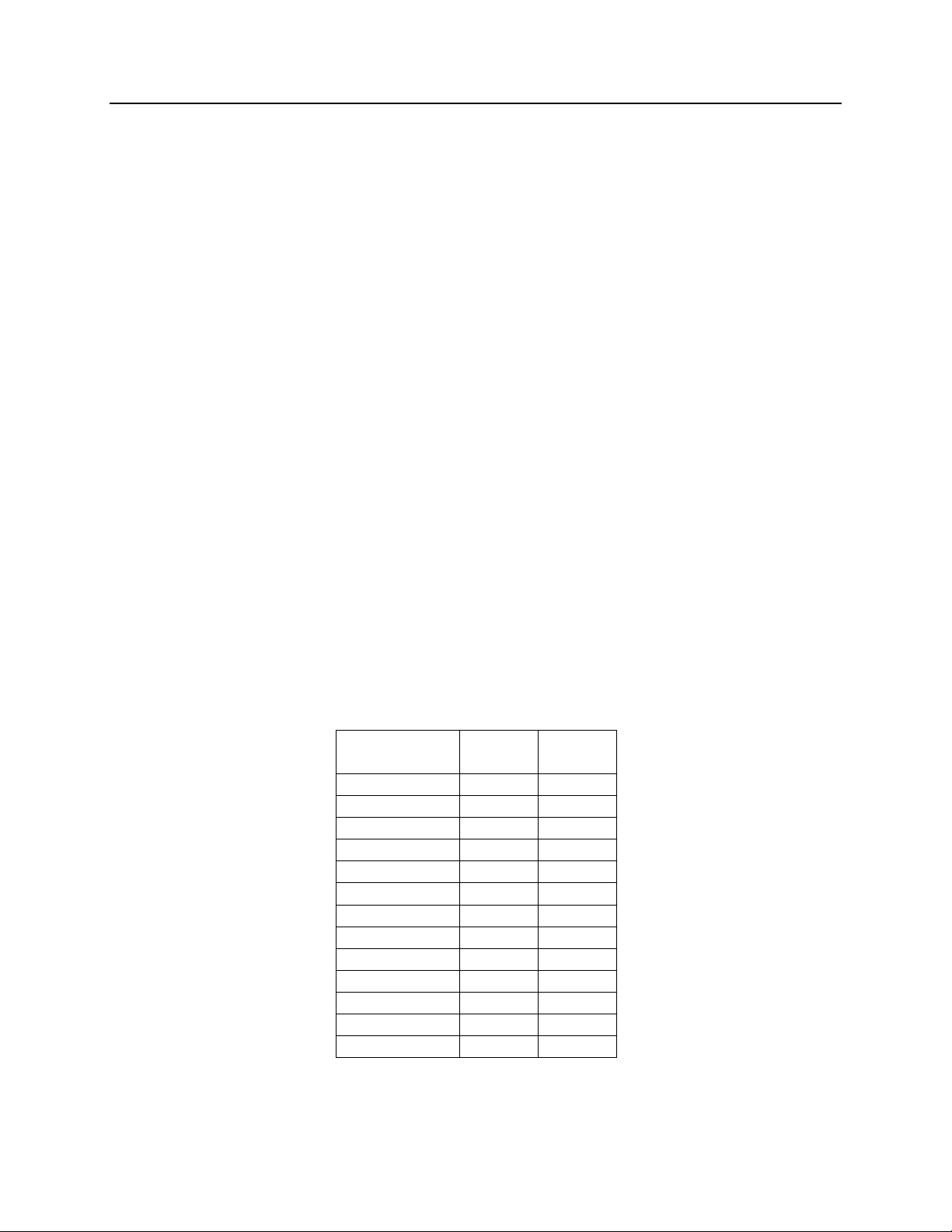
Serial Number tag. The addresses start at Group:Module 00:1 and are
incremented sequentially as shown:
Serial
Number
1001 01 1
1002 01 2
1003 01 3
………
1009 01 9
1010 01 A
1011 01 B
1012 01 C
1013 01 D
1014 01 E
1015 01 F
1016 02 0
1017 02 1
If these addresses conflict with your system's address map, simply change the
CHIB addresses.
Group Module
10
68-11662-100
Page 15

CHIB Hardware Reference Addressing
CTI Products, Inc.
8.3 MCN System Expansion
The CHIB module and its companion AIB/CIB module can reside on an MCN
network with other devices, as long as all MCN units have unique addresses and
the AIB/CIB is addressed at 00:0. It is subject to the same limitations of a
maximum of 20 CIB/AIB/IOB modules and a maximum of 64 modules total on
one physical network.
Multiple CHIB modules can reside on the same MCN network. All CHIBs will
talk to the same AIB or CIB, and all will give the users parallel status and control
functions. One operator can disable a site and an operator at a different console
can re-enable the site later.
A CHIB can talk with only one AIB or CIB module. Since CHIB version 100
looks for the AIB or CIB at a fixed address, they cannot be set to talk to other
AIBs or CIBs that are on the network.
Other CIBs and AIBs can reside on the MCN network, along with PCs using HIBs
or PCLTA modules. The PCs can access all the AIB or CIB modules (including
the one that the CHIB talks to).
11
68-11662-100
Page 16

CHIB Hardware Reference Console Configuration / Mapping
g
g
CTI Products, Inc.
9. Console Configuration / Mapping
The CHIB module emulates 5 CommandSTAR Lite I/O boxes. The receiver
status and control signals are mapped to the I/O Box points as shown below.
Typical programming in CSDM Lite is shown in the rightmost two columns. Use
I/O Type H. LEDs are programmed in pairs.
Pro
I/O Box
Rx Signal Button/LED Address Relay ID Opto ID Output Input
1 Disable Button 30H 0 1
1 Force Vote Button 30H 1 2
1 Disabled LED 30H 0 1
1 Receive LED 30H 1 1
1 Failed LED 30H 2 2
1 Voted LED 30H 3 2
2 Disable Button 30H 2 3
2 Force Vote Button 30H 3 4
2 Disabled LED 30H 4 3
2 Receive LED 30H 5 3
2 Failed LED 30H 6 4
2 Voted LED 30H 7 4
3 Disable Button 30H 4 5
3 Force Vote Button 30H 5 6
3 Disabled LED 30H 8 5
3 Receive LED 30H 9 5
3 Failed LED 30H 10 6
3 Voted LED 30H 11 6
4 Disable Button 31H 0 7
4 Force Vote Button 31H 1 8
4 Disabled LED 31H 0 7
4 Receive LED 31H 1 7
4 Failed LED 31H 2 8
4 Voted LED 31H 3 8
5 Disable Button 31H 2 9
5 Force Vote Button 31H 3 10
5 Disabled LED 31H 4 9
5 Receive LED 31H 5 9
5 Failed LED 31H 6 10
5 Voted LED 31H 7 10
6 Disable Button 31H 4 11
6 Force Vote Button 31H 5 12
6 Disabled LED 31H 8 11
6 Receive LED 31H 9 11
6 Failed LED 31H 10 12
6 Voted LED 31H 11 12
7 Disable Button 32H 0 13
7 Force Vote Button 32H 1 14
7 Disabled LED 32H 0 13
7 Receive LED 32H 1 13
7 Failed LED 32H 2 14
7 Voted LED 32H 3 14
rammin
68-11662-100
12
Page 17

CHIB Hardware Reference Console Configuration / Mapping
g
g
CTI Products, Inc.
I/O Box Pro
Rx Signal Button/LED Address Relay ID Opto ID Output Input
8 Disable Button 32H 2 15
8 Force Vote Button 32H 3 16
8 Disabled LED 32H 4 15
8 Receive LED 32H 5 15
8 Failed LED 32H 6 16
8 Voted LED 32H 7 16
9 Disable Button 32H 4 17
9 Force Vote Button 32H 5 18
9 Disabled LED 32H 8 17
9 Receive LED 32H 9 17
9 Failed LED 32H 10 18
9 Voted LED 32H 11 18
10 Disable Button 33H 0 19
10 Force Vote Button 33H 1 20
10 Disabled LED 33H 0 19
10 Receive LED 33H 1 19
10 Failed LED 33H 2 20
10 Voted LED 33H 3 20
11 Disable Button 33H 2 21
11 Force Vote Button 33H 3 22
11 Disabled LED 33H 4 21
11 Receive LED 33H 5 21
11 Failed LED 33H 6 22
11 Voted LED 33H 7 22
12 Disable Button 33H 4 23
12 Force Vote Button 33H 5 24
12 Disabled LED 33H 8 23
12 Receive LED 33H 9 23
12 Failed LED 33H 10 24
12 Voted LED 33H 11 24
13 Disable Button 34H 0 25
13 Force Vote Button 34H 1 26
13 Disabled LED 34H 0 25
13 Receive LED 34H 1 25
13 Failed LED 34H 2 26
13 Voted LED 34H 3 26
14 Disable Button 34H 2 27
14 Force Vote Button 34H 3 28
14 Disabled LED 34H 4 27
14 Receive LED 34H 5 27
14 Failed LED 34H 6 28
14 Voted LED 34H 7 28
15 Disable Button 34H 4 29
15 Force Vote Button 34H 5 30
15 Disabled LED 34H 8 29
15 Receive LED 34H 9 29
15 Failed LED 34H 10 30
15 Voted LED 34H 11 30
rammin
68-11662-100
13
Page 18

CHIB Hardware Reference Remote Operation
CTI Products, Inc.
10. Remote Operation
Because of the protocol between the CommandSTAR Lite console and the CHIB
module, modem connection between the CHIB and the console is not supported.
The CHIB must always be connected locally to the console (within the appropriate
RS-485 or RS-232 distance limits).
If display and control of a remote comparator is required, this can be done with
standard MCN EXB Network Extender Modules. These modules are available in
the following versions:
Model Description
S2-60602 MCN EXB Module with Internal 2W/4W Leased Line Modem
Certified for US, Canada, and UK operation.
Can also be used on private leased lines that are not subject to
PTT approval requirements.
S2-60655 MCN EXB-SER Module with (2) RS-232 ports
For use with external modems or digital channel banks.
The EXB modules would be inserted in the MCN network between the CHIB and
the AIB or CIB.
14
68-11662-100
Page 19

CHIB Hardware Reference Mounting
CTI Products, Inc.
11. Mounting
Please refer to reference 1,
module.
Make sure that any mounting screws used to secure unit to a bracket do not
protrude into the unit’s enclosure more than 1/8 inches from the bottom surface of
the unit.
Using a larger screw that touches the PC board inside the unit may damage the
unit when it is powered. Doing so will void the unit’s warranty.
Mounting Options,
CAUTION
for details of mounting the CHIB
15
68-11662-100
Page 20

CHIB Hardware Reference Troubleshooting
CTI Products, Inc.
12. Troubleshooting
This table is a list of troubleshooting tips specific to the CHIB module. For
additional troubleshooting tips, refer to the troubleshooting section found in the
Monitoring and Control Network System Manual
Due to the high percentage of surface-mount components, the CHIB is treated as a
field replaceable unit. If any system problems are the result of a malfunctioning
HIB unit, the entire unit must be replaced and returned for repair.
PROBLEM CAUSE
, reference 1.
Green Power LED
Off
Green Power LED
Blinking
Net Act /Reset LED
is on solid
CONSOLE Link
(Yellow) LED Off
No Input DC Voltage.
Check power supply and/or input network connection
Input DC Voltage is too low (<10 VDC)
Check power supply and/or input network connection
Bad CHIB module
CHIB and Console are not communicating.
Possible Problems:
1. CHIB Baud Rate Switches
2. Console I/O Cable and/or RS-485 Transition Cable
3. RS485 Converter and/or power supply
4. RS-232 Cable from CHIB to RS485 converter
5. Bad CHIB
6. Bad Console
You can use the LEDs on the RS485 converter to help you
troubleshoot this problem.
You should see the console polling the CHIB on LED DS2.
You should see the CHIB respond on LED DS1.
No Status Updates,
Force Votes or
Disables
This could be anywhere in the system.
1. Check the power LEDs on all equipment.
2. On the CHIB module: Is the Console Link LED on?
If not, see the section
3. Is the ACT LED on the AIB/CIB on?
If not, see the section
4. Verify Address settings on CHIB and AIB/CIB
5. If using an AIB:
Bad AIB Switch Settings
16
"Console Link (Yellow) LED off."
" ACT LED on CIB or AIB is off."
68-11662-100
Page 21

CHIB Hardware Reference Troubleshooting
CTI Products, Inc.
PROBLEM CAUSE
Bad AIB to Astrotac cable
Bad Astrotac
5. If using a CIB
Bad connections to the comparator
Bad CIB
6. Bad console I/O programming, firmware, or module
Status Updates Okay
but no Force-Votes
or Disables
ACT LED on CIB or
AIB is off
Since status updates are okay, the links between the console and
CHIB are okay. Also, the link between the AIB or CIB and the
CHIB is okay (at least in the AIB/CIB to CHIB direction).
(Remember that switch presses must go through the entire system
and than back to the console before the LED comes on.)
Possible problems:
1. Check to see if the ACT LED on CIB or AIB is off.
- Disconnect all other possible CHIBs, HIBs, and IIBs from
the AIB or CIB. (If any of these devices is accessing the AIB
or CIB, the ACT LED will be on.)
- If the ACT LED on the CIB or AIB is off, see the section
labeled:
"If ACT LED on CIB or AIB is off"
.
2. If using a CIB:
Bad wiring to comparator
Improper option switch setting on CIB
Bad CIB
3 If using an AIB:
Bad AIB or Astrotac comparator
CHIB is not talking to the CIB or AIB.
Possible Problems:
1. Check MCN Network Connections
Net Act /Reset LED
blinks
2. Bad Address on AIB or CIB module
(These
must
be set to 00:0.)
3. Bad address on CHIB module
cannot
(It
be set to 00:0.)
4. There may be a duplicate address on a module in the system
5. If using EXB-Serial units, possible data transmission problem
from CHIB side to AIB/CIB side.
6. Bad EXB units
7. Bad CHIB, AIB, or CIB modules
This is a normal condition. This LED will blink when the CHIB
sees updates from the AIB/CIB or when the console sends button
68-11662-100
17
Page 22

CHIB Hardware Reference Troubleshooting
CTI Products, Inc.
PROBLEM CAUSE
presses.
If you disconnect both the network and the serial cable from the
CHIB, you should see a flash on this LED once every 4-5
seconds. If you see a different pattern than this with both the
cables disconnected, the CHIB is bad.
18
68-11662-100
 Loading...