

Page 1
MCN Monitoring and Control Network
Comparator Display System
Channel Control Unit
CCU
Hardware Reference Manual
S2-61085-105
Note:
Jumpers & switch settings vary
depending upon the system.
Be sure to verify jumper and switch settings
before installation
Be sure to set the rotary address switches to the
proper addresses before installing the system.
68-11843-105
Page 2

FCC Statement
This equipment has been tested and found to comply with the limits for a Class A digital device, pursuant to Part 15 of the FCC Rules. These limits are
designed to provide reasonable protection against harmful interference when the equipment is operated in a commercial environment. This equipment
generates, uses, and can radiate radio frequency energy and, if not installed and used in accordance with the instruction manual, may cause harmful
interference to radio communications. Operation of this equipment in a residential area is likely to cause harmful interference in which case the user will be
required to correct the interference at his own expense.
Warning: Changes or modifications to this unit not expressly approved by the party responsible for compliance could void the user’s authority to operate
the equipment.
DOC Statement
This Class A digital apparatus meets all requirements of the Canadian Interference-Causing Equipment Regulations.
Cet appareil numérique de la classe A respecte toutes les exigences du Règlement sur le matériel brouilleur du Canada.
This manual describes products which include copyrighted CTI Products, Inc. computer programs in semiconductor memory. CTI Products, Inc. reserves
all rights for these programs, including the exclusive right to copy or reproduce the copyrighted computer programs in any form. No copyrighted computer
program contained in products described in this manual may be copied, reproduced, decompiled, disassembled, or reversed engineered in any manner
without express written permission of CTI Products, Inc. The purchase of products from CTI Products, Inc. shall not be deemed to grant either directly or
by implication, estoppel, or otherwise, any license under the copyrights, patents, or patent applications of CTI Products, Inc., except for the normal nonexclusive, royalty fee license to use that arises by operation of law in the sale of the product.
Information contained in this document is subject to change without notice and does not represent a commitment on the part of CTI Products, Inc.
Computer Software Copyrights
No part of this manual may be reproduced or transmitted in any form or by any means, electronic or mechanical, including photocopying and recording, for
any purpose without the written permission of CTI Products, Inc.
Copyright 1995-2005 CTI Products, Inc. All rights reserved.
MCN, CIB, CCU and MCNRCD are trademarks of CTI Products, Inc. Other trademarks referenced are properties of their respective owners.
68-11843-105
Page 3

CCU Hardware Reference
CTI Products, Inc.
Standard Limited Hardware Warranty
LIMITED WARRANTY. Equipment manufactured by CTI Products, Inc. is warranted to be free from defects in material and workmanship for a period
of ONE (1) YEAR from date of shipment to original purchaser. Under this warranty, our obligation is limited to repairing or replacing any equipment
proved to be defective by our inspection within one year of sale to the original purchaser. This warranty shall not apply to equipment which has been
repaired outside our plant in any way, so as to, in the judgment of CTI Products, Inc. affect its stability or reliability, nor which has been operated in a
manner exceeding its specifications, nor which has been altered, defaced, or damaged by lightning.
CUSTOMER REMEDIES. In the event of a defect, malfunction, or failure to conform to specifications established by the seller during the period shown,
the customer shall call CTI Products, Inc. to obtain a Return Authorization Number and return the product or module, shipping and insurance prepaid. CTI
Products, Inc., will then at its option, either repair or replace the product or module and return it, shipping prepaid, or refund the purchase price thereof.
On-site labor at the purchaser's location is not included in this warranty.
EQUIPMENT NOT MANUFACTURED BY CTI Products, Inc. Equipment not manufactured by CTI Products, Inc. is excluded from this warranty,
but is subject to the warranty provided by its manufacturer, a copy of which will be supplied to you upon specific written request.
NO OTHER WARRANTIES. The foregoing constitutes the sole and exclusive remedy of the buyer and exclusive liability of CTI Products, Inc., AND IS
IN LIEU OF ANY AND ALL OTHER WARRANTIES EXPRESSED OR IMPLIED OR STATUTORY AS TO MERCHANTABILITY, FITNESS FOR
PURPOSE SOLD, DESCRIPTION, QUALITY, PRODUCTIVENESS OR ANY OTHER MATTER.
NO LIABILITY FOR CONSEQUENTIAL DAMAGES. WITHOUT LIMITING THE FOREGOING, IN NO EVENT SHALL CTI
PRODUCTS, INC. OR ITS SUPPLIERS BE LIABLE FOR ANY DAMAGES WHATSOEVER (INCLUDING, WITHOUT LIMITATION,
SPECIAL, INCIDENTAL OR CONSEQUENTIAL DAMAGES OR FOR LOSS OF BUSINESS PROFITS, BUSINESS INTERRUPTION,
LOSS OF BUSINESS INFORMATION, OR OTHER PECUNIARY LOSS) ARISING OUT OF THE USE OF OR INABILITY TO USE CTI
PRODUCTS, INC. EQUIPMENT BY PURCHASER OR OTHER THIRD PARTY, WHETHER UNDER THEORY OF CONTRACT, TORT
(INCLUDING NEGLIGENCE), INDEMNITY, PRODUCT LIABILITY OR OTHERWISE, EVEN IF CTI PRODUCTS, INC. HAS BEEN
ADVISED OF THE POSSIBILITY OF SUCH DAMAGES OR LOSSES. IN NO EVENT SHALL CTI PRODUCTS, INC.’S, LIABILITY
EXCEED THE TOTAL AMOUNT PAID BY PURCHASER FOR THE EQUIPMENT GIVING RISE TO SUCH LIABILITY
68-11843-105
i
Page 4

CCU Hardware Reference
Phone: (513) 595
-5900. (8:30 to 5:00 Eastern)
CTI Products, Inc.
Manual Revisions:
S2-61085-100 Original Release for CCU Version 100 (with two toggle inputs).
S2-61085-105 Covers CCU Version 105 (with three sets of toggle inputs).
68-11843-105
CTI Products, Inc.
1211 W. Sharon Rd.
Cincinnati, OH 45240
ii
Page 5

CCU Hardware Reference
CTI Products, Inc.
TABLE OF CONTENTS
1. INTRODUCTION................................................................................................................1
1.1 R
EFERENCE DOCUMENTS
........................................................................................................1
2. SPECIFICATIONS..............................................................................................................2
3. THEORY OF OPERATION ..............................................................................................4
3.1 T
3.2 S
3.3 S
OGGLE SECTION OVERVIEW
ECTION 1 - MAIN / STANDBY BASE SELECTION
ECTION 2 - REPEATER CONTROL
..................................................................................................4
...........................................................................................6
.....................................................................5
3.3.1 Forced Repeater Disable ................................................................................................6
3.4 S
3.5 S
3.6 S
ECTION 3 – COMPARATOR
ECTION 4 – RX NORMAL /
ECTION 5 – TX NORMAL /
A/B S
ECS S
ECS S
ELECT
.................................................................................7
ELECT
ELECT
................................................................................7
................................................................................8
3.6.1 Slaved TX Select..............................................................................................................8
3.7 S
ECTION 6 –
TSAM F
ORCE SELECT OUTPUT
..........................................................................8
4. OPTION SWITCHES & JUMPERS.................................................................................9
4.1 G
4.2 O
4.3 J
ROUP & MODULE SWITCHES
PTION SWITCHES
UMPER OPTIONS
..................................................................................................................9
..................................................................................................................10
................................................................................................9
5. CONNECTORS.................................................................................................................11
6. MOUNTING.......................................................................................................................14
7. OPERATION IN AN MCN NETWORK........................................................................15
8. TROUBLESHOOTING....................................................................................................16
68-11843-105
iii
Page 6

CCU Hardware Reference
CTI Products, Inc.
68-11843-105
iv
Page 7
CCU Hardware Reference Introduction
CTI Products, Inc.
1. Introduction
The CCU Channel Control Units are used to control functions in a Land Mobile
Radio System such as:
Main / Standby Base
Repeat On/Off
Comparator A / Comparator B
Receive: Normal / Emergency Control Station (ECS)
Transmit: Normal / ECS
The CCU allows three independent consoles to control the above functions. It
allows each console to toggle the functions and provides feedback to the consoles
to indicate the state of each function. If one console fails, the others may continue
to control the system functions.
The CCU provides status indication of each function on the MCN (Monitoring
and Control Network), similar to a CIB module. It also allows the functions to be
toggled from a PC running the MCN Remote Comparator Display (MCNRCD)
software.
The CCU is a CIB Comparator Interface Module with special firmware.
ERR
IN NETWORK OUT
DC IN
8
9
8
9
7
7
A
6
B
6
5
C
5
4
D
4
3
E
3
2
F
2
0
1
0
1
PWR ACT
MODULEGROUP
8
9
7
A
A
B
6
B
C
5
C
D
4
D
E
3
E
F
2
F
0
1
123 4
ON
RESET
OPTION
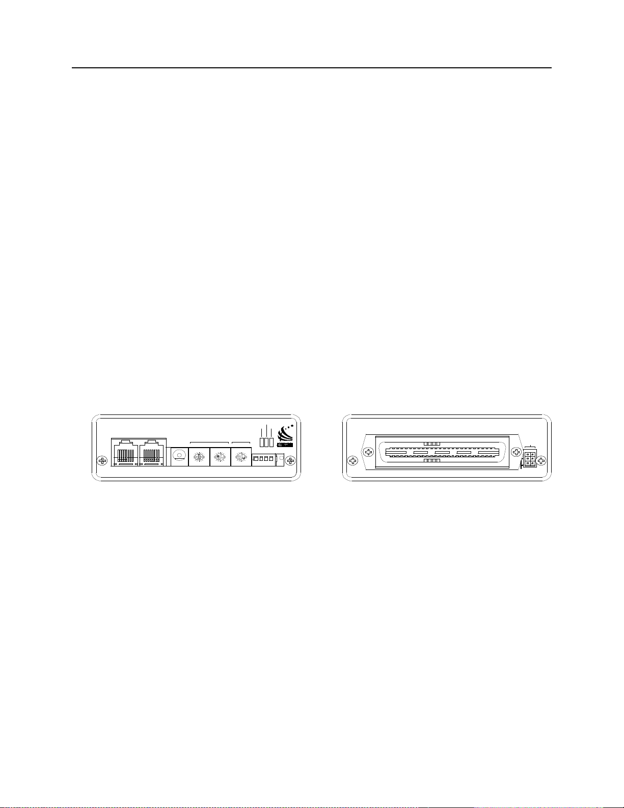
Figure 1 - CCU Front and Rear View
1.1 Reference Documents
1. Monitoring and Control Network System Manual
Part Number S2-60425
E1 A
J1
E1 B
CA-80023-105
68-11843-105
1
Page 8
CCU Hardware Reference Specifications
CTI Products, Inc.
2. Specifications
Size 5.5” x 4.2” x 1.5”
(140 x 107 x 38 mm)
Weight 16 oz (455 gm)
Temperature 0 - 50 ºC
Humidity 10 - 95% non-condensing
Module Power 10 - 32 Vdc / 2 Watts max.
Number of Sections Supported 5 Toggle Sections
1 TSAM Force Select Section
Open Circuit Voltage (all I/O pins)
jumper E1B removed
jumper E1B installed
Inputs per Toggle Section
active low, pull-up to +5 or +15 Vdc
Input Voltage (Input and In/Out pins) -0.6 to 30 Vdc max
Input Current (Input and In/Out pins):
jumper E1B removed (Vin = 0 Vdc)
jumper E1B installed (Vin = 0 Vdc)
Outputs per Toggle Section (active low) (4): Normal 1, Normal 2
Outputs per TSAM Force Select Section (1) Force Select
Output Saturation Voltage (Outputs and
In/Out pins) with Iout = 100 mA
Output Pin Current (Outputs and In/Out
pins)
Maximum Power Dissipation 2 Watts
Input/Output Connection 50 pin Telco style
Network Connector (2) RJ-45 (1 in, 1 out)
Safety Approvals UL 1950
Emissions Compliance FCC Part 15, Class A
Susceptibility Compliance IEC 801-2
+15 Vdc nominal
+5 Vdc nominal
(3), Toggle 1, Toggle 2, & Toggle 3
-720 µA max (source)
-270 µA max (source)
Inverted 1, Inverted 2
(See circuit description for specific
Output names)
550 mV max.
100 mA max per pin (sink)
Each output can drive (1) relay on an
RYB-8 board.
CSA 1950
EN 60950-1992
DOC Class A
EN55022
IEC 801-3
IEC 801-4
EN50082-1
Table 1 - Module Specifications
68-11843-105
2
Page 9

CCU Hardware Reference Specifications
CTI Products, Inc.
Figure 2 shows the equivalent circuits of the CCU I/O pins. The pull-up voltage
Vp is controlled by jumper E1B, located on the rear of the module.
• Vp = 15 Vdc with jumper E1B out (Default setting)
• Vp = 5.0 Vdc with jumper E1B in
+5V
HCMOS
IC
INPUT
+5V
180K
150K
Vp
22K
INPUT
Vp
22K
0.01uF
0.01uF
ESD
PROTECTION
ESD
PROTECTION
30V
TRANSORB
30V
TRANSORB
OUTPUT
Vp
22K
ESD
PROTECTION
+5V
30V
HCMOS
IC
INPUT
150K
0.01uF
INPUT/OUTPUT
TRANSORB
CA-80043-105
Figure 2 - I/O Equivalent Circuit
68-11843-105
3
Page 10

CCU Hardware Reference Theory of Operation
CTI Products, Inc.
3. Theory of Operation
The CCU contains 5 similar toggle sections:
Main / Standby Base Select
Repeat On/Off
Comparator A / Comparator B Select
Receive: Normal / Emergency Control Station (ECS) Select
Transmit: Normal / ECS Select
Each section is essentially a Toggle Flip-Flop with multiple inputs and outputs.
Depending upon the Option Switch setting, the 5 sections can operate
independently, or there may be some interaction between sections.
There is a sixth section that provides a Force Select output for a TSAM unit.
3.1 Toggle Section Overview
Each of the toggle sections has (3) toggle inputs, (2) "Normal" outputs and (2)
"Inverted" outputs. Normal and inverted outputs are available to drive the console
inputs to allow flexibility in implementation. In most sections, one of the Inverted
outputs will be used as feedback to the console, since it is active in the "abnormal"
condition (Such as Standby, Repeat Disable, ECS, etc.).
Refer to Figure 3 – Main / Standby Base Section Logic for details of a typical
toggle section.
The Toggle inputs are active low. The Flip-Flop will toggle when either input
makes a high to low transition (after a debounce time).
The debounce is followed by a one-shot, and only the leading edge (high to low)
transition is seen from the console. Thus a stuck Toggle output from the console
will not prevent the other console from toggling the function in the CCU.
Outputs are active low. The Normal outputs are active on power-up
Typically, the #1 outputs drive the system control units and the #2 outputs provide
feedback to the consoles.
Status bits provide feedback to PCs on the MCN network. Depending upon the
Display Table used for the particular function, the state of the output(s) and / or
the input(s) can be seen.
Control bits provide input from PCs on the MCN network. Depending upon the
Display Table used for the particular function, the operator may either toggle the
function or explicitly Set or Reset the function.
68-11843-105
4
Page 11

CCU Hardware Reference Theory of Operation
CTI Products, Inc.
3.2 Section 1 - Main / Standby Base Selection
The following logic diagram of the Main / Standby Base Select section shows the
basic section logic.
Main/Stby Base Toggle 1
(CIB Rx 1)
22
Main/Stby Base Toggle 2
(CIB Vote 1)
21
Main/Stby Base Toggle 3
(CIB Dis 7)
2
Ctl Bit 2 Main Base Force On
Stat Bit 1 Main/Stby Base Toggle 1
Debounce One-Shot
Stat Bit 3 Main/Stby Base Toggle 2
Debounce One-Shot
Stat Bit 21 Main/Stby Tgl 3
Debounce
CtlI Bit 1 Main/Stby Toggle 1
Ctl Bit 3 Main/Stby Toggle 2
Ctl Bit 4 Stby Base Force On
One-Shot
System Reset
CA-80877-105 CCU Version 105 Logic Section 1
S (Async)
T
CK +
R (Async)
Q
Q
Figure 3 – Main / Standby Base Section Logic
There are three external inputs:
• /Main/Standby Toggle 1 (from Console 1)
• /Main/Standby Toggle 2 (from Console 2)
• /Main/Standby Toggle 3 (from Console 3)
There are four logic outputs:
• /Main Base Select 1 (Normal) to TSAM TXS1
• /Main Base Select 2 (Normal)
• /Standby Base Select 1 (Inverted) To TSAM TXS2
• /Standby Base Select 2 (Inverted) To Console Input
Stat Bit 2 Main Base Select
2
1
4
21
Stat Bit 4 Stby Base Select
20
19
23
31
/Main Base Select
(CIB Dis 1)
/Main Base Select 2
(CIB Mon 1)
/Stby Base Select
(CIB Fail 1)
/Standby Base Select 2
(CIB Mon 6)
68-11843-105
5
Page 12

CCU Hardware Reference Theory of Operation
CTI Products, Inc.
3.3 Section 2 - Repeater Control
The Repeater Control Section has a similar Toggle function as the Main/Standby
function.
There are three external inputs:
• /Repeat Toggle 1 (from Console 1)
• /Repeat Toggle 2 (from Console 2)
• /Repeat Toggle 3 (from Console 3)
There are four logic outputs:
• /Repeat On 1 (Normal)
• /Repeat On 2 (Normal)
• /Repeat Off 1 (Inverted) To Comparator Repeat Disable Input
• /Repeat Off 2 (Inverted) To Console Input
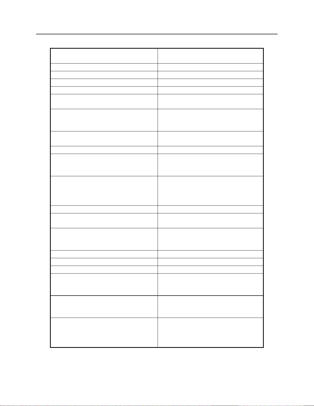
3.3.1 Forced Repeater Disable
The Repeater Control Section can be set up to automatically disable repeat
operation if the Transmit or Receive ECS Station is selected.
Option
Switch Up
2 Forced Repeat Disable when
RX ECS is selected
3 Forced Repeat Disable when
TX ECS is selected
Down
No Forced Repeat Disable on
RX ECS
No Forced Repeat Disable on
TX ECS
Table 2 – Forced Repeat Disable Switches
If the Forced Repeat Disable option is enabled and you set the TX & RX
Norm/ECS selection back to Normal, the Repeat will remain disabled until the
operator re-enables the repeat from the PC or by toggling one of the Repeat Tgl
lines.
68-11843-105
6
Page 13

CCU Hardware Reference Theory of Operation
CTI Products, Inc.
3.4 Section 3 – Comparator A/B Select
The Comparator A/B Select section has a similar Toggle function as the
Main/Standby function.
There are three external inputs:
• /Comp Toggle 1 (from Console 1)
• /Comp Toggle 2 (from Console 2)
• /Comp Toggle 3 (from Console 3)
There are four logic outputs:
• /Comp A Select 1 (Normal)
• /Comp A Select 2 (Normal)
• /Comp B Select 1 (Inverted) To Comp B Select Relay
• /Comp B Select 2 (Inverted) To Console Input
Note that each output can drive only (1) RYB-8 relay. If you need to control
multiple relays (for TX Audio, Rx Audio & COR), you will have to use one relay
to buffer the coils for the other relays.
3.5 Section 4 – RX Normal / ECS Select
The Rx Normal / ECS Select section has a similar Toggle function as the
Main/Standby function.
There are three external inputs:
• /Rx Toggle 1 (from Console 1)
• /Rx Toggle 2 (from Console 2)
• /Rx Toggle 3 (from Console 3)
There are four logic outputs:
• /Rx Normal Select 1 (Normal)
• /Rx Normal Select 2 (Normal)
• /Rx ECS Select 1 (Inverted) To RX ECS Select Relay
• /Rx ECS Select 2 (Inverted) To Console Input
The RX ECS select can be used to disable the comparator repeat function. See
details in Section 2 - Repeater Control.
68-11843-105
7
Page 14

CCU Hardware Reference Theory of Operation
CTI Products, Inc.
3.6 Section 5 – TX Normal / ECS Select
The Tx Normal / ECS Select section has a similar Toggle function as the
Main/Standby function.
There are three external inputs:
• /Tx Toggle 1 (from Console 1)
• /Tx Toggle 2 (from Console 2)
• /Tx Toggle 3 (from Console 3)
There are four logic outputs:
• /Tx Normal Select 1 (Normal)
• /Tx Normal Select 2 (Normal)
• /Tx ECS Select 1 (Inverted) To TX ECS Select Relay
• /Tx ECS Select 2 (Inverted) To Console Input
The TX ECS select can be used to disable the comparator repeat function. See
details in Section 2 - Repeater Control.
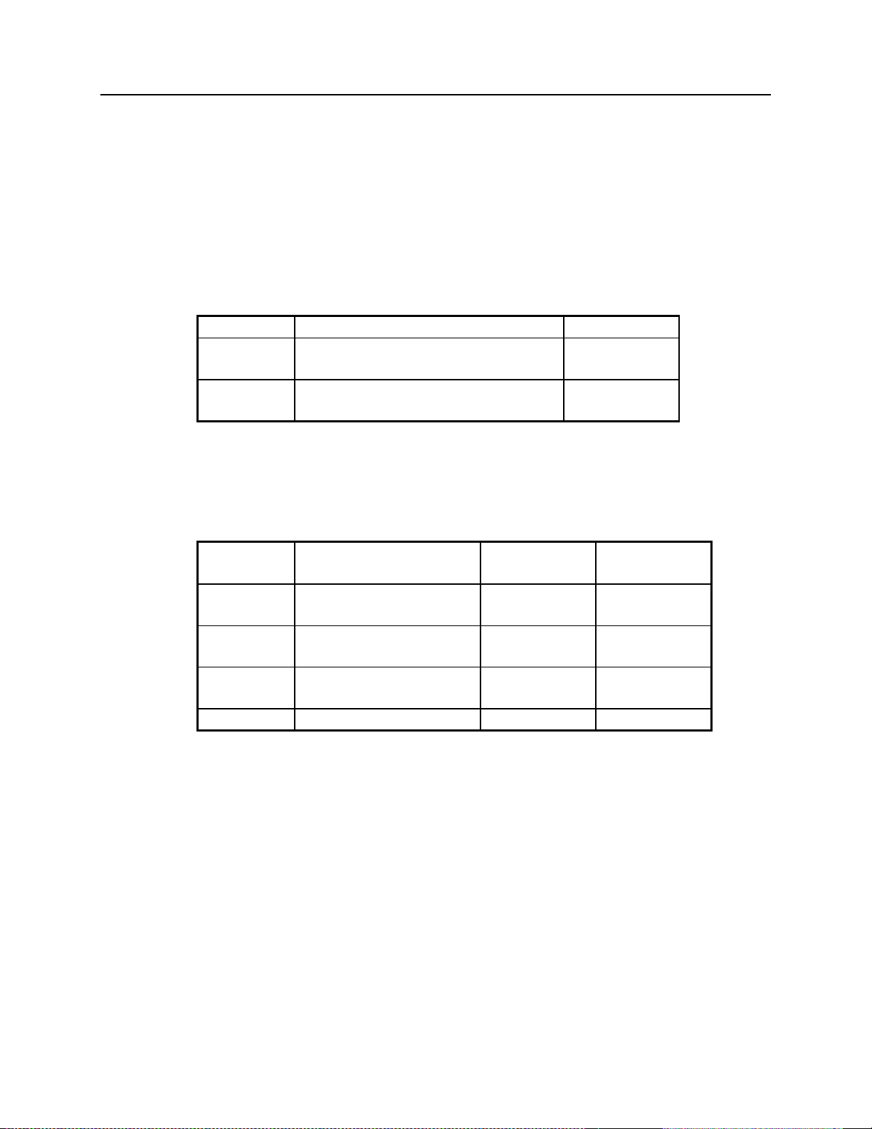
3.6.1 Slaved TX Select
The TX Normal / ECS Select section can be forced to be controlled by Section 4 Rx Normal / ECS Select as shown below:
Option
Switch Up
1 Slave Mode:
TX Normal / ECS Select
controlled by the
Rx Normal / ECS Section
Down
Independent Mode:
TX Normal / ECS Select
operates independently from the
Rx Normal / ECS Section
Table 3 – Slaved TX Select
If the Slaved mode is used, the Toggle inputs to the TX section are not connected.
3.7 Section 6 – TSAM Force Select Output
When one of the Toggle sections (typically the TX Main/Standby) is used to
control the TX Select (TXS1 & TXS2) inputs on the TSAM Transmitter Steering
Unit, the TSAM requires an additional Force Select input. Section 6 provides a
square wave output with a period of about 1 Hz. This ensures that the TSAM's
outputs will switch within 1 second of the output change in the CCU.
The Force Select output is not fed back to the MCNRCD network, since it would
only add a lot of unnecessary channel traffic.
68-11843-105
8
Page 15
CCU Hardware Reference Switches & Jumpers
CTI Products, Inc.
4. Option Switches & Jumpers
Three sets of option switches are provided for module configuration. The module
must be power cycled or reset after these switches are set so that the options will
take effect.
4.1 Group & Module Switches
The Group and Module selector switches are used to set the node address during
module installation. Refer to the Monitor and Control Network System Manual
for details about setting these switches.
SWITCH DESCRIPTION DEFAULT
GROUP unit address setting (00-FE)
refer to the MCN System Manual
MODULE unit address setting (0-F)
refer to the MCN System Manual
Table 4 – Group & Module Switches
00
0
4.2 Option Switches
The Option switches control special functions of the CCU.
OPTION
SWITCH
1 TX Normal / ECS Slave
2 Force Repeat Disable
3 Force Repeat Disable
4 not used
DESCRIPTION Up Down
when Rx ECS selected
when Tx ECS selected
Table 5 - Option Switches
Slaved to RX Independent
Mode
Forced Normal
Forced Normal
68-11843-105
9
Page 16

CCU Hardware Reference Switches & Jumpers
CTI Products, Inc.
4.3 Jumper Options
Figure 4 shows the configuration of the two jumper options available on the rear
of the CCU. These jumpers should be installed at system installation time with
power removed from the CCU.
E1 A
E1 B
CA-80024-100
Figure 4 - Jumper Options
Jumper E1A is located across the top 2 terminals of the 6 pin terminal block.
Jumper E1B is located across the left side middle and bottom terminals of the 6
pin terminal block. The remaining 2 terminals of the block are unused.
Jumper Function Default
E1A In to enable output TX ECS Select 2.
IN
E1B In for inputs pulled up to +5 Vdc.
OUT
Out for inputs pulled up to +15 Vdc.
Table 6 - Jumper Options Description
68-11843-105
10
Page 17

CCU Hardware Reference Connectors
CTI Products, Inc.
5. Connectors
The NETWORK IN/OUT ports on the front of the CCU are used to connect the
CCU with other MCN modules. These ports carry both the network data signals
as well as DC power for power distribution with other modules. Table 7 gives the
pinout for these connectors. Figure 5 shows the location of pin 1 for each port.
PRODUCTS, INC.
IN
PIN 1
NETWORK
OUT
DC IN
CA-80068-100
Figure 5 - Network IN/OUT Ports
Pin Function
1 DATA +
2 DATA 3 + POWER
4 No Connect
5 No Connect
6 - POWER
7 - POWER
8 + POWER
Table 7 - Network Connector Pinout
The DC IN port provides the primary power connection to the module. Power is
distributed through the NETWORK OUT connector to provide power to the
NETWORK IN connector of the MCN unit it is connected to. Each power
supply can power up to four units total. See reference 1 for complete details of
connections to the network and DC IN connectors.
Connector J1 provides the discrete I/O signals. The following tables show the
pinouts in Logical and Punch-Block order. Since this module uses CIB hardware,
the old CIB functions and Hardware Pin I/O types are listed for all pins.
68-11843-105
11
Page 18

CCU Hardware Reference Connectors
CTI Products, Inc.
Table 8 - CCU Connector J1 Pinout in Logical Order
HW
CCU
Pin
CIB
J1
I/O
Funct.
22 I Rx 1 1 In Main/Stby Tgl 1 CEB 1 Main/Stby Tgl
21 I/O Vote 1 1 In Main/Stby Tgl 2 CEB 2 Main/Stby Tgl
2 I/O Dis 7 1 In Main/Stby Tgl 3 CEB 3 Main/Stby Tgl
20 I/O Dis 1 1 Out Main Sel Active TSAM /TXS1 Pin 11
19 O Mon 1 1 Out Main Sel 2 Active
23 I/O Fail 1 1 Out Stby Sel TSAM /TXS2 Pin 37
31 O Mon 6 1 Out Standby Sel 2 CEB Input Stby Indication
47 I Rx 2 2 In Repeat Tgl 1 CEB 1 Repeat Tgl
46 I/O Vote 2 2 In Repeat Tgl 2 CEB 2 Repeat Tgl
28 I/O Vote 8 2 In Repeat Tgl 3 CEB 3 Repeat Tgl
45 I/O Dis 2 2 Out Repeat On Active
44 O Mon 2 2 Out Repeat On 2
48 I/O Fail 2 2 Out Repeat Off Comparator Rpt Disable
33 I/O Dis 6 2 Out Repeat Off 2 CEB Input Rpt Off Indication
16 I Rx 3 3 In Comp A/B Tgl 1 CEB 1 Comp A/B Tgl
15 I/O Vote 3 3 In Comp A/B Tgl 2 CEB 2 Comp A/B Tgl
3 I/O Vote 7 3 In Comp A/B Tgl 3 CEB 3 Comp A/B Tgl
14 I/O Dis 3 3 Out Comp A Sel Active
12 O Mon 3 3 Out Comp A Sel 2
17 I/O Fail 3 3 Out Comp B Sel Comp Ry Comp B Ry Ctrl
34 I/O Vote 6 3 Out Comp B Sel 2 CEB Input Comp B Indication
41 I Rx 4 4 In Rx Norm/ECS Tgl 1 CEB 1 Rx Norm/ECS Tgl
40 I/O Vote 4 4 In Rx Norm/ECS Tgl 2 CEB 2 Rx Norm/ECS Tgl
29 I RX8 4 In Rx Norm/ECS Tgl 3 CEB 3 Rx Norm/ECS Tgl
39 I/O Dis 4 4 Out Comp Rx Sel Active
37 O Mon 4 4 Out Comp Rx Sel 2 Active
42 I/O Fail 4 4 Out ECS Rx Sel Rx Source Ry ECS RX RY Ctrl
36 I/O Fail 6 4 Out ECS Rx Sel 2 CEB Input ECS Rx Indication
10 I Rx 5 5 In Tx Norm/ECS Tgl 1 CEB 1 Tx Norm/ECS Tgl
9 I/O Vote 5 5 In Tx Norm/ECS Tgl 2 CEB 2 Tx Norm/ECS Tgl
4 I Rx 7 5 In Tx Norm/ECS Tgl 3 CEB 3 Tx Norm/ECS Tgl
8 I/O Dis 5 5 Out Norm TX Sel Active TX
6 O Mon 5 5 Out Norm TX Sel 2 Active CEB Input
11 I/O Fail 5 5 Out ECS TX Sel Tx Ry ECS TX RY Ctrl
18 O Mon 7 5 Out ECS Tx Sel 2 CEB Input ECS Tx Indication
26 O Mon 8 6 Out Force Sel Toggles TSAM /ForceSel Pin 28
35 I Rx 6
5 I/O Fail 7
27 I/O Dis 8
30 I/O Fail 8
1 Gnd Ground Ground System All Grounds
CCU
Sect.
CCU
I/O CCU I/O Function Default Connects To: Function
68-11843-105
12
Page 19

CCU Hardware Reference Connectors
CTI Products, Inc.
Table 9 - CCU Connector J1 Pinout in Punch Block Order
CCU
HW
CIB
J1
I/O
Funct.
26 O Mon 8 6 Out Force Sel Toggles TSAM /ForceSel Pin 28
1 Gnd Ground Ground System All Grounds
27 I/O Dis 8
2 I/O Dis 7 1 In Main/Stby Tgl 3 CEB 3 Main/Stby Tgl
28 I/O Vote 8 2 In Repeat Tgl 3 CEB 3 Repeat Tgl 3
3 I/O Vote 7 3 In Comp A/B Tgl 3 CEB 3 Comp A/B Tgl 3
29 I Rx 8 4 In Rx Norm/ECS Tgl 3 CEB 3 Rx Norm/ECS Tgl
4 I Rx 7 5 In Tx Norm/ECS Tgl 3 CEB 3 Tx Norm/ECS Tgl
30 I/O Fail 8
5 I/O Fail 7
31 O Mon 6 1 Out Standby Sel 2 CEB Input Stby Indication
6 O Mon 5 5 Out Norm TX Sel 2 Active CEB Input
32 unused
7 unused
33 I/O Dis 6 2 Out Repeat Off 2 CEB Input Rpt Off Indication
8 I/O Dis 5 5 Out Norm TX Sel Active TX
34 I/O Vote 6 3 Out Comp B Sel 2 CEB Input Comp B Indication
9 I/O Vote 5 5 In Tx Norm/ECS Tgl 2 CEB 2 Tx Norm/ECS Tgl
35 I Rx 6
10 I Rx 5 5 In Tx Norm/ECS Tgl 1 CEB 1 Tx Norm/ECS Tgl
36 I/O Fail 6 4 Out ECS Rx Sel 2 CEB Input ECS Rx Indication
11 I/O Fail 5 5 Out ECS TX Sel Tx Ry ECS TX RY Ctrl
37 O Mon 4 4 Out Comp Rx Sel 2 Active
12 O Mon 3 3 Out Comp A Sel 2
38 unused
13 unused
39 I/O Dis 4 4 Out Comp Rx Sel Active
14 I/O Dis 3 3 Out Comp A Sel Active
40 I/O Vote 4 4 In Rx Norm/ECS Tgl 2 CEB 2 Rx Norm/ECS Tgl
15 I/O Vote 3 3 In Comp A/B Tgl 2 CEB 2 Comp A/B Tgl
41 I Rx 4 4 In Rx Norm/ECS Tgl 1 CEB 1 Rx Norm/ECS Tgl
16 I Rx 3 3 In Comp A/B Tgl 1 CEB 1 Comp A/B Tgl
42 I/O Fail 4 4 Out ECS Rx Sel Rx Source Ry ECS RX RY Ctrl
17 I/O Fail 3 3 Out Comp B Sel Comp Ry Comp B Ry Ctrl
43 unused
18 O Mon 7 5 Out ECS Tx Sel 2 CEB Input ECS Tx Indication
44 O Mon 2 2 Out Repeat On 2
19 O Mon 1 1 Out Main Sel 2 Active
45 I/O Dis 2 2 Out Repeat On Active
20 I/O Dis 1 1 Out Main Sel Active TSAM /TXS1 Pin 11
46 I/O Vote 2 2 In Repeat Tgl 2 CEB 2 Repeat Tgl
21 I/O Vote 1 1 In Main/Stby Tgl 2 CEB 2 Main/Stby Tgl
47 I Rx 2 2 In Repeat Tgl 1 CEB 1 Repeat Tgl
22 I Rx 1 1 In Main/Stby Tgl 1 CEB 1 Main/Stby Tgl
48 I/O Fail 2 2 Out Repeat Off Comparator Rpt Disable
23 I/O Fail 1 1 Out Stby Sel TSAM /TXS2 Pin 37
49 unused
24 unused
50 unused
25 unused
CCU
Sect.
CCU
I/O CCU I/O Function Default
Connects
To: Function
68-11843-105
13
Page 20

CCU Hardware Reference Mounting
CTI Products, Inc.
6. Mounting
Various mounting kits are available to mount the CCU module.
Mounting Kits
Rack Mount - 4 A size modules
1 Rack Unit (1.75") High
Rack Mount - 2 A size modules plus 1 B size module
1 Rack Unit (1.75") High
(Used to mount 2 CCUs and 1 EXB module.)
Refer the reference 1, section Mounting Options, for physical details about
mounting the CCU module.
S2-60435
S2-60443
68-11843-105
14
Page 21

CCU Hardware Reference Troubleshooting
CTI Products, Inc.
7. Operation in an MCN Network
The CCU can be seen in an MCN network as a CIB unit or as a CCU unit. If the
MCNRCD software is configured to see it as a CIB unit, only the first 5 (toggle)
sections will be active as Function Blocks.
For each function block (section) of the CCU, you will have to select an
appropriate Display Table to use. Standard CCU Display Tables are:
Section Type Display Table Typical Display
1 Main/Standby Base CCU Base Main / Stby
2 Repeater On/.Off CCU Rptr On / Off
3 Comparator A/B CCU Comparator Comp A / Comp B
4 RX Norm/ECS CCU ECS Norm / ECS
5 TX Norm/ECS CCU ECS Norm / ECS
Table 10 – MCNRCD CCU Display Tables
Each of these Display Tables allow the user to toggle the function with the left or
right mouse function. These tables may be customized if desired. See the
MCNRCD Software Manual for details. The bit values for display and mouse
functions are shown below.
Table
3 2 1 0
Display Toggle 1 In Q (Norm) Toggle 2 In /Q (Inverted)
Mouse Toggle 1 Force Set Toggle 2 Force Reset
Bit
Table 11 –CCU Display Table & Mouse Bit Functions
The Toggle 1 In and Toggle 2 In reflect the state of the Tgl 1 & Tgl 2 inputs for
the particular section of the CCU being monitored. They will normally be "Don't
Care" bits in dispatch displays. They can be displayed (in a special bit-wise
display table) for use by a technician to verify that the Toggle signals from the
consoles are being seen at the CCU.
Normally the Toggle mouse actions will be used. The Force Set and Force Reset
functions are available to explicitly set and reset the functions. They are provided
to allow a special CCU device descriptor to be made for the MCNRCD software.
The Display Table entries for the CCU can be configured to generate logging or
alarms if desired.
68-11843-105
15
Page 22

CCU Hardware Reference Troubleshooting
CTI Products, Inc.
8. Troubleshooting
This table is a list of troubleshooting tips specific to the CCU module. For
additional troubleshooting tips, refer to the troubleshooting section found in the
Monitoring and Control Network System Manual, reference 1.
Due to the high percentage of surface-mount components, the CCU is treated as a
field replaceable unit. If any system problems are the result of a malfunctioning
CCU unit, the entire unit must be replaced and returned for repair.
PROBLEM CAUSE
Signals do not toggle Verify that the appropriate inputs are going to ground. If you are
using relay contacts to drive the Toggle inputs, be sure the
common side of the relay contacts are grounded and connected to
Pin 1 of the CCU.
TX ECS doesn't change when
TX ECS Toggle inputs are
changed
Can't enable the Repeater
from the PC or with the Rpt
Toggle inputs.
TSAM not switching audio
outputs
Data from CCU changes,
when I/O lines are static
The ACT LED on the CCU is
off
You may have TX ECS slaved to RX ECS. Check Option
Switch 1.
You may have Force Repeat enabled. (Switches 2 & 3). If so,
when the Rx ECS Select or the TX ECS Select is active, you will
not be able to turn the Repeat On until the RX and/or TX ECS is
turned off.
Be sure that /TXS1, /TXS2, /Force Sel, and Ground are
connected to the TSAM and are acting properly..
You probably have multiple CCUs programmed for the same
Group/Module address. Reset the addresses and reset the
appropriate CCUs.
For instance, one CCU may have Comparator A selected and
another may have Comparator B selected. You will see the
indication change between Comp A & Comp B.
This is a normal condition if there is no PC accessing the CCU at
any given time.
68-11843-105
16
Page 23

CCU Hardware Reference Troubleshooting
CTI Products, Inc.
The standard CIB-T Switch & LED Test Board may be used to test the functionality of the CCU
module. Switch and LED assignments appear below.
M/S 2
M/S 1
TxNrm1TxNrm2
ECSTxT2 ECSTxT1
1
26
Mn1Mn2 Sb1
TxECS1
5
30
RPT1 RPT2
CmpB2
10
35
Sb2
15
40
RpOn1RpOn2 RpOff1
RxECS2
RpOff2
20
25
45
50
CmpA1CmpA2 CmpB1
CMPT1
CMPT2
TxECS2
ECSTxT3
M/S 3
CMPT3
P1
ECSRxT2
RPT3
TB1
+ +
ECSRxT3
+
C1
FrcSel
- -
RxNrm1RxNrm2 RxECS1
ECSRxT1
J1
J2
CA-80704-110CIB-T Labeling for CCU Testing
Signal names were shortened to fit them on the labels:
Main/Stby Tgl 1 M/S1 Rx Norm/ECS Tgl 1 ECSRxT1
Main/Stby Tgl 2 M/S2 Rx Norm/ECS Tgl 2 ECSRxT2
Main/Stby Tgl 3 M/S3 Rx Norm/ECS Tgl 3 ECSRxT3
Main Sel Mn1 Comp Rx Sel RxNrm1
Main Sel 2 Mn2 Comp Rx Sel 2 RxNrm2
Stby Sel Sb 1 ECS Rx Sel RxECS1
Standby Sel 2 Sb 2 ECS Rx Sel 2 RxECS2
Repeat Tgl 1 RPT1 Tx Norm/ECS Tgl 1 ECSTxT1
Repeat Tgl 2 RPT2 Tx Norm/ECS Tgl 2 ECSTxT2
Repeat Tgl 2 RPT3 Tx Norm/ECS Tgl 3
ECSTxT3
2
Repeat On RpOn1 Norm TX Sel TxNrm1
Repeat On 2 RpOn2 Norm TX Sel 2 TxNrm2
Repeat Off RpOff1 ECS TX Sel TxECS1
Repeat Off 2 RpOff2 ECS Tx Sel 2 TxECS2
Comp A/B Tgl 1 CMPT1 Force Sel FrcSel
Comp A/B Tgl 2 CMPT2
Comp A/B Tgl 3 CMPT3
Comp A Sel CmpA1
Comp A Sel 2 CmpA2
Comp B Sel CmpB1
Comp B Sel 2 CmpB2
68-11843-105
17
Page 24

 Loading...