

Page 1
MCN Monitoring and Control Network
Comparator Display System
ASTRO-TAC™ Comparator Interface
Module
AIB
Hardware Reference Manual
S2-60399-115
NOTE: This module must be configured before being installed in your system. Refer to section 4 for
information about the module configuration.
68-10842-115
Page 2

FCC Statement
This equipment has been tested and found to comply with the limits for a Class A digital device, pursuant to Part 15 of the FCC Rules. These
limits are designed to provide reasonable protection against harmful interference when the equipment is operated in a commercial environment.
This equipment generates, uses, and can radiate radio frequency energy and, if not installed and used in accordance with the instruction manual,
may cause harmful interference to radio communications. Operation of this equipment in a residential area is likely to cause harmful
interference in which case the user will be required to correct the interference at his own expense.
Warning: Changes or modifications to this unit not expressly approved by the party responsible for compliance could void the user’s authority to
operate the equipment.
DOC Statement
This Class A digital apparatus meets all requirements of the Canadian Interference-Causing Equipment Regulations.
Cet appareil numérique de la classe A respecte toutes les exigences du Règlement sur le matériel brouilleur du Canada.
Computer Software Copyrights
This manual describes products which include copyrighted CTI Products, Inc. computer programs in semiconductor memory. CTI Products, Inc.
reserves all rights for these programs, including the exclusive right to copy or reproduce the copyrighted computer programs in any form. No
copyrighted computer program contained in products described in this manual may be copied, reproduced, decompiled, disassembled, or
reversed engineered in any manner without express written permission of CTI Products, Inc. The purchase of products from CTI Products, Inc.
shall not be deemed to grant either directly or by implication, estoppel, or otherwise, any license under the copyrights, patents, or patent
applications of CTI Products, Inc., except for the normal non-exclusive, royalty fee license to use that arises by operation of law in the sale of the
product.
Information contained in this document is subject to change without notice and does not represent a commitment on the part of CTI Products,
Inc.
No part of this manual may be reproduced or transmitted in any form or by any means, electronic or mechanical, including photocopying and
recording, for any purpose without the written permission of CTI Products, Inc.
Copyright 1995, 1996, CTI Products, Inc. All rights reserved.
MCN is a trademark of CTI Products, Inc. ASTRO-TAC is a trademark of Motorola, Inc. Other trademarks referenced are properties of their
respective owners.
68-10842-115
Page 3

AIB Hardware Reference
CTI Products, Inc.
Standard Limited Hardware Warranty
LIMITED WARRANTY.
for a period of ONE (1) YEAR from date of shipment to original purchaser. Under this warranty, our obligation is limited to repairing or
replacing any equipment proved to be defective by our inspection within one year of sale to the original purchaser. This warranty shall not apply
to equipment which has been repaired outside our plant in any way, so as to, in the judgment of CTI Products, Inc. affect its stability or
reliability, nor which has been operated in a manner exceeding its specifications, nor which has been altered, defaced, or damaged by lightning.
Equipment manufactured by CTI Products, Inc. is warranted to be free from defects in material and workmanship
CUSTOMER REMEDIES
period shown, the customer shall call CTI Products, Inc. to obtain a Return Authorization Number and return the product or module, shipping
and insurance prepaid. CTI Products, Inc., will then at its option, either repair or replace the product or module and return it, shipping prepaid,
or refund the purchase price thereof. On-site labor at the purchaser's location is not included in this warranty.
EQUIPMENT NOT MANUFACTURED BY CTI Products, Inc.
warranty, but is subject to the warranty provided by its manufacturer, a copy of which will be supplied to you upon specific written request.
NO OTHER WARRANTIES.
Inc., AND IS IN LIEU OF ANY AND ALL OTHER WARRANTIES EXPRESSED OR IMPLIED OR STATUTORY AS TO
MERCHANTABILITY, FITNESS FOR PURPOSE SOLD, DESCRIPTION, QUALITY, PRODUCTIVENESS OR ANY OTHER MATTER.
NO LIABILITY FOR CONSEQUENTIAL DAMAGES.
PRODUCTS, INC. OR ITS SUPPLIERS BE LIABLE FOR ANY DAMAGES WHATSOEVER (INCLUDING, WITHOUT LIMITATION,
SPECIAL, INCIDENTAL OR CONSEQUENTIAL DAMAGES OR FOR LOSS OF BUSINESS PROFITS, BUSINESS INTERRUPTION,
LOSS OF BUSINESS INFORMATION, OR OTHER PECUNIARY LOSS) ARISING OUT OF THE USE OF OR INABILITY TO USE CTI
PRODUCTS, INC. EQUIPMENT BY PURCHASER OR OTHER THIRD PARTY, WHETHER UNDER THEORY OF CONTRACT, TORT
(INCLUDING NEGLIGENCE), INDEMNITY, PRODUCT LIABILITY OR OTHERWISE, EVEN IF C TI PR ODUCTS, INC. HAS BEEN
ADVISED OF THE POSSIBILITY OF SUCH DAMAGES OR LOSSES. IN NO EVENT SHALL CTI PRODUCTS, INC.’S, LIABILITY
EXCEED THE TOTAL AMOUNT PAID BY PURCHASER FOR THE EQUIPMENT GIVING RISE TO SUCH LIABILITY.
. In the event of a defect, malfunction, or failure to conform to specifications established by the seller during the
Equipment not manufactured by CTI Products, Inc. is excluded from this
The foregoing constitutes the sole and exclusive remedy of the buyer and exclusive liability of CTI Products,
WITHOUT LIMITING THE FOREGOING, IN NO EVENT SHALL CTI
68-10842-115
i
Page 4

AIB Hardware Reference
CTI Products, Inc.
CTI Products, Inc.
1211 W. Sharon Rd.
Cincinnati, OH 45240
If you have questions about the MCN comparator display system, call us at:
(513) 595-5900. (8:30 to 5:00 Eastern)
68-10842-115
ii
Page 5

AIB Hardware Reference
CTI Products, Inc.
1. INTRODUCTION..................................................................................................................... 1
1.1 R
EFERENCE DOCUMENTS
........................................................................................................... 1
2. THEORY OF OPERATION.................................................................................................... 2
2.1 C
OMPARATOR STATUS
2.2 C
ONTROLLING THE COMPARATOR
2.3 L
OSS OF COMMUNICATIONS
2.4 S
YSTEM EXAMPLE
............................................................................................................... 2
.............................................................................................. 2
....................................................................................................... 3
...................................................................................................................... 4
3. SPECIFICATIONS................................................................................................................... 5
4. OPTION SWITCHES............................................................................................................... 6
5. CONNECTORS......................................................................................................................... 8
6. MOUNTING ............................................................................................................................ 10
7. SETTING GROUP/MODULE SWITCHES ........................................................................ 10
8. SPECIAL FEATURES ........................................................................................................... 11
8.1 L
INK FAILURE REPORTING
....................................................................................................... 11
9. TROUBLESHOOTING ......................................................................................................... 12
iii
68-10842-115
Page 6
AIB Hardware Reference Introduction
CTI Products, Inc.
1. Introduction
The ASTRO-TAC™ Comparator Interface Module (AIB) is a member of the
Monitoring and Control Network (MCN™) family of Comparator I/O Modules.
Hardware specifications, special installation, and configuration information are
described in this manual.
The AIB module connects a Motorola ASTRO-TAC™ (VSELP signaling) or
ASTRO-TAC™ 3000 (APCO Project 25 IMBE signaling) Comparator to the
MCN network. An AIB is used with an MCN User Interface Module, Motorola’s
ASTRO-TAC™ or ASTRO-TAC™ 3000 Comparator and a user interface device,
such as a console or PC, to create a comparator display system. The comparator
display system provides monitoring and control functions for your
communications system. Receiver states monitored by the AIB include VOTE,
RECEIVE, DISABLE and FAIL. Receiver functions that can be controlled
include FORCE VOTE and DISABLE.
PRODUCTS, INC.
IN
OUTNETWORK
DC IN
RESET SVC
PWR
OPTION A
ON
12345678
ERR
ACT
HOST
5
SER
1234
MODE
8
7
6
5
4
6789
3
2
1
ON
12
MODULEGROUP
8
9
A
B
C
D
E
F
0
8
9
9
A
A
7
7
B
B
6
6
C
5
4
3
C
5
4
D
D
E
E
3
F
F
2
2
1
1
0
0
ON
CA-80022-100
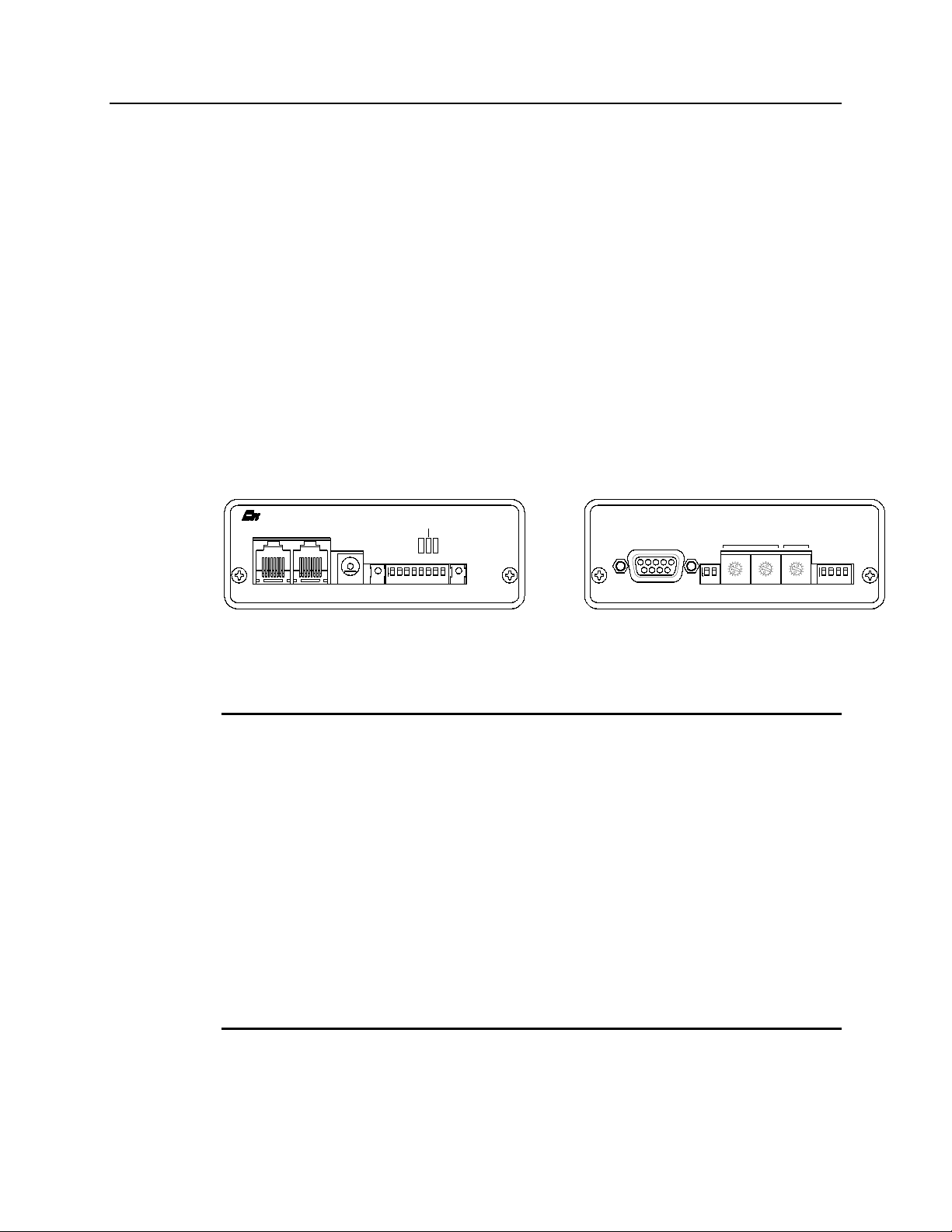
Figure 1 - AIB Front and Rear View
This manual applies only to AIB modules with model number S2-60331-nnn,
where ‘nnn’ is the number 110 or greater (this is the module’s version number).
This model number can be found on the rear panel of the module.
If the module’s version number is greater than 110, there may be additional
features supported by the module that are not covered in this manual. Refer to the
AIB module backward compatibility cross reference sheet supplied with this
manual to find out if the module has features not discussed in this manual.
New features added to version 110 include the following:
• support for the ASTRO-TAC™ 3000
OPTION B
1234
For the remainder of this manual, all references to the ASTRO-TAC™
Comparator include the ASTRO-TAC™ 3000 as well, unless stated otherwise.
1.1 Reference Documents
1. Monitoring and Control Network Comparator Display System Manual
Part Number S2-60425
68-10842-115
1
Page 7

AIB Hardware Reference Theory of Operation
CTI Products, Inc.
2. Theory of Operation
This section describes the operation of the AIB module in an MCN comparator
display system.
The AIB module must be configured for the comparator it is operating with, either
an ASTRO-TAC™ or an ASTRO-TAC™ 3000 Comparator. Section 4 describes
the ASTRO-TAC™ select option switch used for this configuration
When used with an ASTRO-TAC™ 3000 Comparator, the AIB provides
monitoring and control for up to 64 receivers. The AIB divides the receivers into
eight banks for compatibility with the MCN network. The defined receiver banks
are
• bank 0 supports receivers 1 through 8
• bank 1 supports receivers 9 through 16
• bank 2 supports receivers 17 through 24
• bank 3 supports receivers 25 through 32
• bank 4 supports receivers 33 through 40
• bank 5 supports receivers 41 through 48
• bank 6 supports receivers 49 through 56
• bank 7 supports receivers 57 through 64
When used with an ASTRO-TAC™ Comparator, the AIB provides monitoring
and control for up to 13 receivers, dividing the receivers into two banks (banks 0
and 1).
When installing a system, make sure that the User Interface Module is configured
for the correct bank for the receivers being monitored and controlled by the User
Interface Module. Refer to the hardware reference manual of the User Interface
Module for details about bank configuration.
2.1 Comparator Status
The AIB accepts VOTE, RECEIVE, DISABLE, and FAIL receiver status
messages from the ASTRO-TAC™ Comparator and sends them to a User
Interface Module over the MCN network. User Interface Modules, such as the IIB
(I/O Interface Module) or HIB (Host Computer Interface Module) then display the
comparator status information on a console or PC.
2.2 Controlling the Comparator
When a User Interface Module sends FORCE VOTE or DISABLE commands, the
AIB translates the commands for the ASTRO-TAC™ Comparator and sends them
to the comparator.
68-10842-115
2
Page 8

AIB Hardware Reference Theory of Operation
CTI Products, Inc.
The AIB updates the ASTRO-TAC™ Comparator with the latest control
information every second and whenever a FORCE VOTE or DISABLE command
is received from a User Interface Module.
2.3 Loss of Communications
In the unlikely event that the MCN network link between the AIB and all of its
User Interface Modules is broken (the AIB is no longer communicating with any
User Interface Module, therefore its ACT LED will turn off), the AIB will send a
message to the ASTRO-TAC™ Comparator clearing any active FORCE VOTES.
Active DISABLE inputs from the User Interface Module(s) are not changed if
MCN network communications is lost.
68-10842-115
3
Page 9
AIB Hardware Reference Theory of Operation
CTI Products, Inc.
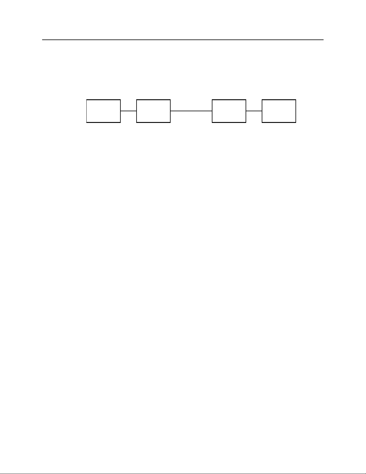
2.4 System Example
Figure 2 shows an example comparator display system using the AIB module and
ASTRO-TAC™ Comparator.
OPERATOR
STATION
USER
INTERFACE
MODULE
MCN NETWORK
AIB
ASTROTAC
COMPARATOR
CA-80040-100
Figure 2 - AIB System Example
When the ASTRO-TAC™ Comparator detects that a receiver is active, it sends a
RECEIVE command followed by a VOTE command (if that receiver becomes
voted). The AIB processes these commands and sends them to the User Interface
Module. The User Interface Module then indicates that the receiver is active and
voted. If the User Interface Module is an IIB, the IIB activates the VOTE and RX
outputs for that receiver’s status display.
If the comparator detects that a receiver has failed, then it will send a FAIL
command to the AIB. Again, the AIB sends this FAIL command to the User
Interface Module so that the user can see that the receiver has failed.
One issue to note, however, is that if Motorola’s RSS (Radio Service Software) is
used to disable a receiver, the comparator does not send the DISABLE
information to the AIB. The MCN comparator display system will not show that
receiver as being disabled, even though it truly is disabled in the comparator.
From the operator station, the user can generate FORCE VOTE or DISABLE
commands for each receiver in the system. The User Interface Module detects
these commands and sends them to the AIB. The AIB then sends a command to
the ASTRO-TAC™ Comparator, telling it which receivers were force voted or
disabled.
In this example, if the User Interface Module is an IIB, the IIB has to be
configured for bank 0 to operate with receivers 1 through 8 of the ASTRO-TAC™
Comparator or configured for bank 1 to operate with receiver 9 through 13. If the
User Interface Module is a HIB with the MCN Remote Comparator Display
software running on a PC, only bank 0 (receivers 1 through 8) can be monitored
and controlled. Refer to the hardware reference manual of the User Interface
Module for details about bank configuration.
68-10842-115
4
Page 10

AIB Hardware Reference Specifications
CTI Products, Inc.
3. Specifications
Size 5.5” x 4.2” x 1.5” (140 x 107 x 38 mm)
Weight 16 oz (455 gm)
Temperature 0 - 50 ºC
Humidity 10 - 95% non-condensing
Module Power 10 - 32 Vdc / 2 Watts max.
Number of Receivers Supported 13 when configured for ASTRO-TAC™ mode
64 when configured for ASTRO-TAC™ 3000 mode
Comparator Connector 9 pin D-SUB, female
Network Connector (2) RJ-45 (1 in, 1 out)
Safety Approvals UL 1950
CSA 1950
EN 60950-1992
Emissions Compliance FCC Part 15, Class A
DOC Class A
EN55022
Susceptibility Compliance IEC 801-2
IEC 801-3
IEC 801-4
EN50082-1
ASTRO-TAC™ Comparator
Firmware Version 1.7 or later
ASTRO-TAC™ 3000 Comparator
Firmware Version Any version is compatible with the AIB module.
Table 1 - Module Specifications
5
68-10842-115
Page 11
AIB Hardware Reference Option Switches
CTI Products, Inc.
4. Option Switches
Five sets of option switches are provided for module configuration. The module
must be power cycled or reset after these switches are set so that the options will
take effect. Table 2 describes the option switches and shows the factory defaults.
SWITCH MODULE DESCRIPTION DEFAULT
GROUP unit address setting
(refer to the MCN System Manual)
MODULE unit address setting
(refer to the MCN System Manual)
OPTION A
position 1 not used
position 2 not used UP
position 3 not used UP
position 4 not used UP
position 5 not used UP
position 6 not used UP
position 7 not used UP
position 8 ASTRO-TAC™ select DOWN
OPTION B
position 1 not used
position 2 not used UP
position 3 synchronous clock selection, see Table 4 UP
position 4 synchronous clock selection, see Table 5 UP
SER MODE
position 1 synchronous clock selection, see Table 4
position 2 synchronous clock selection, see Table 5 DOWN
00
0
UP
UP
DOWN
Table 2 - AIB Option Switches
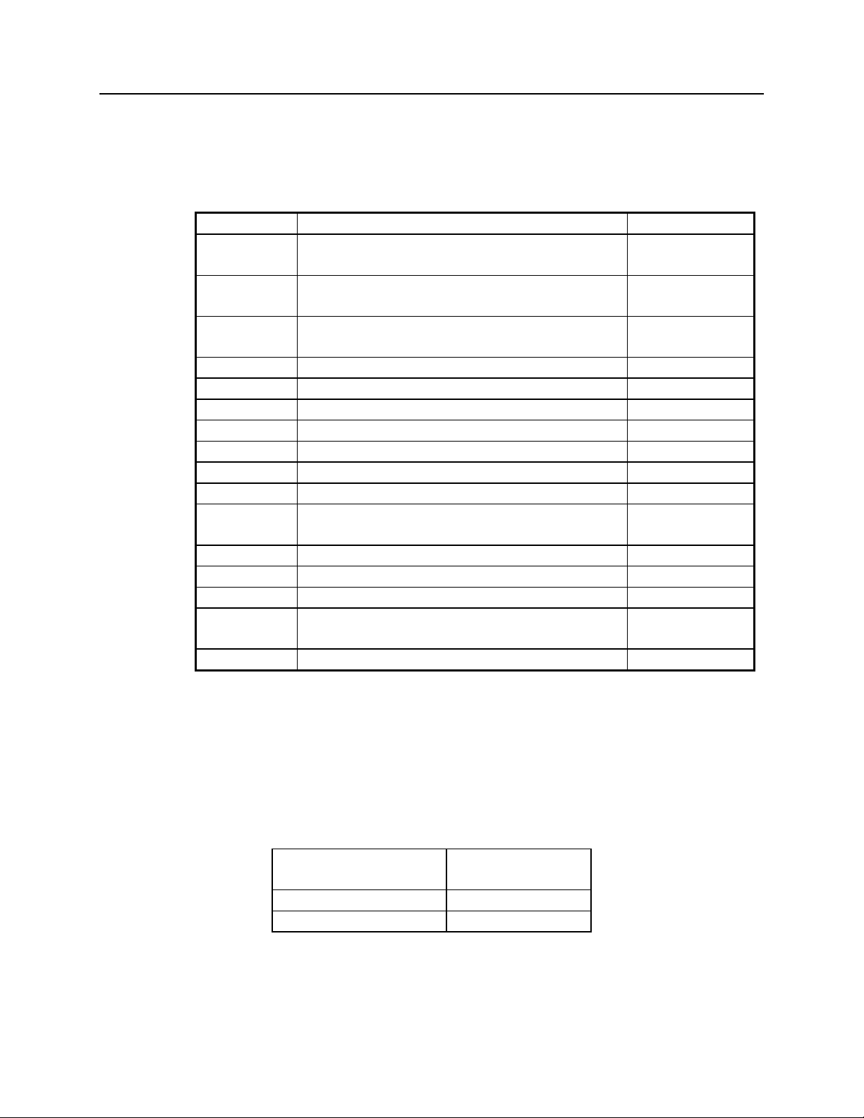
Table 3 shows the setting for the ASTRO-TAC™ select switch. This switch
configures the AIB to operate with either the ASTRO-TAC™ comparator
(supporting up to 13 receivers) or the ASTRO-TAC™ 3000 comparator
(supporting up to 64 receivers). If this switch is not set properly, the AIB will not
communicate with the comparator.
Option A Switch
Comparator Type
ASTRO-TAC™ 3000 DOWN
ASTRO-TAC™ UP
Table 3 - ASTRO-TAC Select Switch
Table 4 and Table 5 show the configurations for the synchronous clock selection
switches found on the rear of the module. The default positions (internal TX
6
position 8
68-10842-115
Page 12

AIB Hardware Reference Option Switches
CTI Products, Inc.
Clock and RX Clock) are used for direct connection between the AIB and
ASTRO-TAC™ Comparator.
TX Clock Source
SER MODE
position 1
OPTION B
position 3
Internal (default) DOWN UP
External UP DOWN
Table 4 - Transmit Clock Selection
RX Clock Source
SER MODE
position 2
OPTION B
position 4
Internal (default) DOWN UP
External UP DOWN
Table 5 - Receive Clock Selection
68-10842-115
7
Page 13

AIB Hardware Reference Connectors
CTI Products, Inc.
5. Connectors
The NETWORK IN/OUT ports on the front of the AIB are used to connect the
AIB with other MCN modules. These ports carry both the network data signals
and the DC power for power distribution with other modules. Table 6 gives the
pinout for these connectors. Figure 3 shows the location of pin 1 for each port.
PRODUCTS, INC.
IN
PIN 1
OUTNETWORK
DC IN
CA-80068-100
Figure 3 - Network IN/OUT Ports
Pin Function
1 DATA +
2 DATA 3+ POWER
4 No Connect
5 No Connect
6- POWER
7- POWER
8+ POWER
Table 6 - Network Connector Pinout
The DC IN port provides the primary power connection to the module. Power is
distributed through the NETWORK OUT connector to provide power to the
NETWORK IN connector of the MCN unit it is connected to. Each power
supply can power up to four units total. See reference 1 for complete details of
connections to the network and DC IN connectors.
68-10842-115
8
Page 14

AIB Hardware Reference Connectors
CTI Products, Inc.
AIB HOST
Connector
DE9-female
Signal Name
Cable
Connector
DE9-male Direction
Cable Connector
DB25-male
ASTRO-TAC™
Comparator
J15
DB25-female
Signal Name
RXD 2 < 2 TxD3
TXD 3 > 3 RxD3
CTS 7 < 4 RTS3
RTS 8 > 5 CTS3
DTR 1 > 6, 8 DSR3, DCD3
Ground 5 7 Signal Ground
RCLK 9 > 15 TCLK3
TCLK 6 > 17 RCLK3
DCD 4 < 20 DTR3
Chassis Gnd shell 1 Shield Gnd
Table 7 - AIB <--> Comparator Communication Cable
The HOST connector (9 pin D-SUB female) on the rear of the AIB is used to
connect the module to connector J15 (25 pin D-SUB female) on the back of the
ASTRO-TAC™ Comparator. This port is a synchronous RS-232 port operating
at 9600 baud. Table 7 gives the pinout of the AIB to ASTRO-TAC™ Comparator
communications cable.
This cable is available as an accessory to the AIB. The part number for ordering
this cable is S2-60440.
68-10842-115
9
Page 15

AIB Hardware Reference Mounting
CTI Products, Inc.
6. Mounting
Please refer to reference 1,
module.
Make sure that any mounting screws used to secure unit to a bracket do not
protrude into the unit’s enclosure more than 1/8 inches from the bottom surface of
the unit.
Using a larger screw that touches the pc board inside the unit may damage the unit
when it is powered. Doing so will void the unit’s warranty.
Mounting Options,
CAUTION
for details of mounting the AIB
7. Setting Group/Module Switches
Please refer to the MCN System Manual, reference 1,
for details about the Group and Module switches on the AIB module.
Setting the Unit Address,
10
68-10842-115
Page 16

AIB Hardware Reference Special Features
CTI Products, Inc.
8. Special Features
The AIB module was designed with specific features/functions that help make the
system easier to use and maintain.
8.1 Link Failure Reporting
During normal operation, the AIB and the ASTRO-TAC™ Comparator
communicate by exchanging data and status information. If the communications
between the two devices stop (the comparator is turned off or the communications
cable is removed), the AIB will generate a special message onto the MCN
network, telling all User Interface Modules assigned to that AIB that the
comparator communication link has failed.
Some User Interface Modules have the ability to report this link failure. How this
link failure is shown depends on the type of User Interface Module being used.
Refer to the User Interface Module’s hardware reference manual to find out if it
supports this link failure reporting.
11
68-10842-115
Page 17

AIB Hardware Reference Troubleshooting
CTI Products, Inc.
9. Troubleshooting
This table is a list of troubleshooting tips specific to the AIB module. For
additional troubleshooting tips, refer to the troubleshooting section found in the
Monitoring and Control Network System Manual
Due to the high percentage of surface-mount components the AIB is treated as a
field replaceable unit. If any system problems are the result of a malfunctioning
AIB unit, the entire unit must be replaced and returned for repair.
PROBLEM CAUSE
, reference 1.
User Interface
Module is not
showing a disabled
receiver when the
receiver is disabled
at the ASTROTAC™ Comparator
User Interface
Module reports a
link fail error for the
AIB
This is normal. If Motorola’s RSS (Radio Service Software) is
used to disable a receiver, the ASTRO-TAC™ Comparator does
not send that information to the AIB. The MCN comparator
display system will not show that receiver as being disabled, even
though it truly is disabled in the comparator.
Verify that the AIB is properly connected to the comparator.
Verify that the AIB’s OPTION A, switch 8 is set for the proper
comparator type. If not, change the switch and reset the AIB.
12
68-10842-115
Page 18

AIB Hardware Reference Troubleshooting
CTI Products, Inc.
PROBLEM CAUSE
User interface is not
showing correct
status
OR
Operator cannot
FORCE VOTE or
DISABLE the
receivers
Verify that the AIB’s OPTION A, switch 8 is set for the proper
comparator type. If not, change the switch and reset the AIB.
Connect the cable between the AIB and the ASTRO-TAC™
Comparator.
TX and RX Clocks
Using an oscilloscope or breakout box, verify that a 9600 KHz
signal (50% duty cycle) is present on the ASTRO-TAC™
Comparator J15 connector, pins 15 (Tx Clk) and 17 (Rx Clk) (± 3
to ± 12 Vdc swing). If not, verify that the AIB OPTION B
switches 3 and 4 are in the UP position and the AIB SER MODE
switches 1 and 2 are in the DOWN position. If the switches are
correct, verify the continuity of the cable:
DE9 pin 9 to DB25 pin 15
DE9 pin 6 to DB25 pin 17
If the cable is ok, the AIB is not functioning properly. Replace
the AIB.
AIB to ASTRO-TAC™ Comparator Data
Verify that every 1 to 5 seconds, a short burst of data occurs on
the ASTRO-TAC™ Comparator J15 connector, pin 3, RXD (± 3
to ± 12 Vdc swing). If not, verify the continuity of the cable:
DE9 pin 3 to DB25 pin 3
If the wire is ok, the AIB is not functioning properly. Replace
the AIB.
ASTRO-TAC™ Comparator to AIB Data
Verify that at least every few seconds, a short burst of data occurs
on the AIB HOST connector, pin 2, RXD (± 3 to ± 12 Vdc
swing). If not, verify the continuity of the cable:
DE9 pin 2 to DB25 pin 2
If the wire is ok, the ASTRO-TAC™ Comparator is not
functioning properly. Repair the ASTRO-TAC™ Comparator.
Control Signals
Verify that AIB HOST connector pins 4 (DCD) and 7 (CTS) are
active (+6 to +12 Vdc). If not, verify the continuity of the cable:
DE9 pin 4 to DB25 pin 20
DE9 pin 7 to DB25 pin 4
68-10842-115
If the wires are ok, the ASTRO-TAC™ Comparator is not
13
functioning properly.
Page 19

AIB Hardware Reference Troubleshooting
CTI Products, Inc.
14
68-10842-115
 Loading...