

Page 1
OPERATING INSTRUCTIONS
AND PARTS MANUAL
WARNING
ATENCION
ATTENTION
4275 N.W. PACIFIC RIM BLVD. ■ CAMAS, WA 98607 ■ USA
For technical assistance or the Dealer nearest you, call (360) 833-1600
Page 2

2
Page 3

CONTENTS
Introduction ................................................................................................................................... 4
Important Safety Information .........................................................................................................4
General Operating Techniques ......................................................................................................4
Alignment Tool, #95-0728030 ........................................................................................................5
Exploded View .............................................................................................................................. 6
Parts List, Exploded View ............................................................................................................. 7
Troubleshooting ............................................................................................................................ 8
Nozzle Chart .................................................................................................................................8
Warranty ....................................................................................................................................... 9
Spanish.................................................................................................................................. 10-12
3
Model Number ______________________________
Serial Number ______________________________
Date of Purchase ____________________________
The model and serial numbers will be found on a decal attached to
the Cyclone. You should record both serial number and date of purchase and keep in a safe place for future reference.
Cyclone System Manual • Form #96-619 • Revised 10/01
Page 4
4
CYCLONE SYSTEM
OPERATOR’S MANUAL
INTRODUCTION
The Cyclone is designed to attach to a pressure washer
which rotates two high pressure nozzles in the Cyclone.
The nozzles produce spray as well as determine the size
of the swath when cleaning surfaces such as parking
lots, driveways and sidewalks.
Owner/User Responsibility:
The owner and/or user must have an understanding of the
manufacturer’s operating instructions and warnings before
using this Cyclone. Warning information should be emphasized and understood. If the operator is not fluent in English, the manufacturer’s instructions and warnings shall
be read to and discussed with the operator in the operator’s
native language by the purchaser/owner, making sure that
the operator comprehends its contents.
Owner and/or user must study and maintain for future
reference the manufacturers’ instructions.
This manual should be considered a permanent
part of the machine and should remain with it if
machine is resold.
When ordering parts, please specify model and
serial number.
IMPORTANT SAFETY
INFORMATION
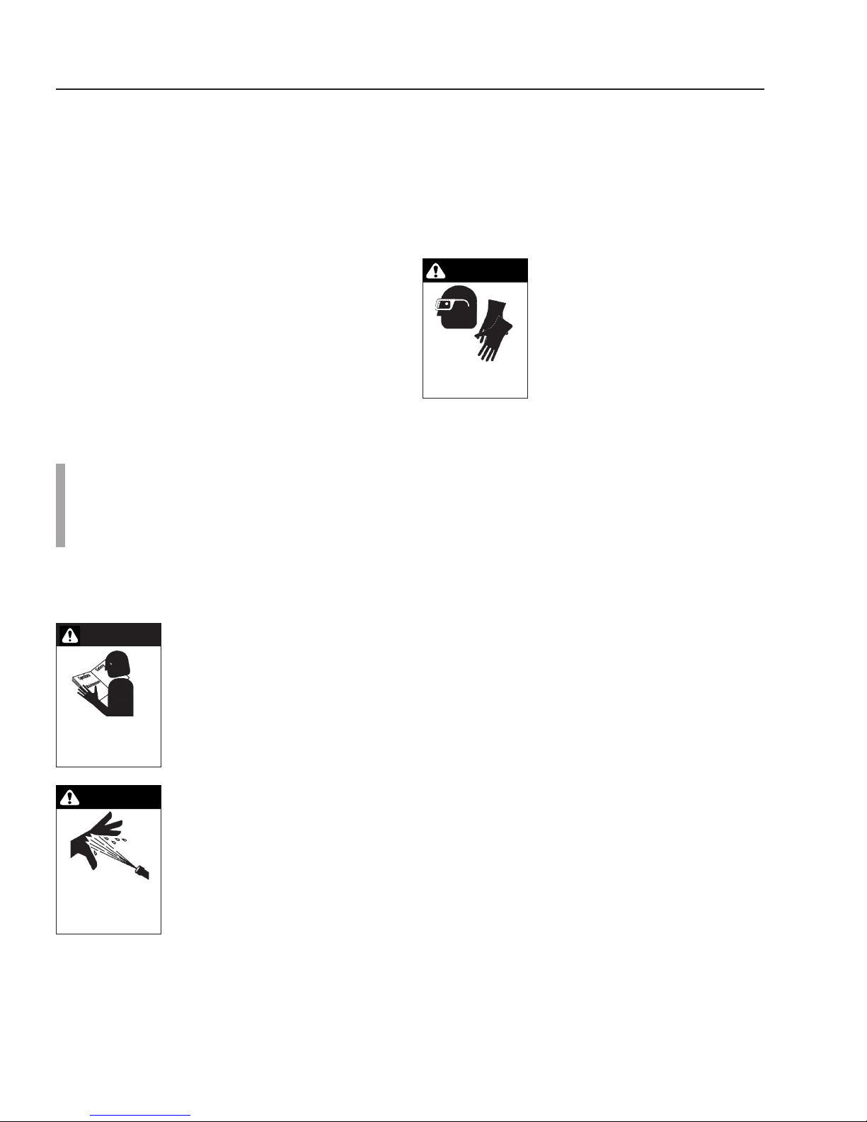
CAUTION
READ OPERATOR’S
MANUAL
THOROUGHLY
PRIOR TO USE
WARNING
HIGH PRESSURE
STREAM CAN
PIERCE SKIN
AND TISSUE
stream at people or animals or severe injury or death
will result.
3. Never make adjustments on machine while it is in
operation.
4. Eye safety devices and foot protection must be worn
when using this equipment.
CAUTION: To reduce the risk of injury, read operating instructions
carefully before using.
1. Read the owner’s manual thoroughly. Failure to follow instructions could cause malfunction
of the machine and result in
death, serious bodily injury and/
or property damage.
WARNING: High pressure stream of
fluid that equipment can produce
can pierce skin and its underlying
tissues, leading to serious injury.
2. High pressure developed by
these machines will cause personal injury or equipment damage. Use caution when operating. Do not direct discharge
5. The best insurance against an accident is precaution and knowledge of the machine.
6. Never expose any parts of the body, such as feet or
fingers, to the underside of base when spray arms
are rotating. Never tilt or attempt to work on underside of base while pressure washer is running or
spray arms are rotating.
WARNING
WARNING: High pressure spray
can cause paint chips or other particles to become airborne and fly
at high speeds.
7. Safety clothing and protective
USE PROTECTIVE
CLOTHING WHEN
OPERATING.
9. We will not be liable for any alterations made to our
standard machines, or the application of any components not purchased from us.
10. Pressure must NOT exceed 4,000 PSI. Temperature must NOT exceed 200°F. Flow rate must NOT
exceed 6 GPM.
11. To protect from freezing, squeeze the trigger lever
after you turn off the pressure washer and have disconnected the high pressure hose from the Cyclone.
This will allow water to drain through the nozzles.
eye covering must be worn.
8. The Cyclone comes equipped
with two #3 nozzles in the rotating swivel. Check your machine nozzle size before using.
GENERAL OPERATING
TECHNIQUES
1. Disconnect pressure washer spray gun from high pressure hose. These items are not included, but are provided with the soon to be attached pressure washer.
2. Attach the female nipple, supplied with the Cyclone,
to the pressure washer high pressure hose.
NOTE: We recommend using no mar hose to
prevent black marks from appearing on the cleaning surface.
3. Couple pressure washer high pressure hose to Cyclone.
4. Inspect your pressure washer nozzle size. The Cyclone surface cleaner comes with two #3 nozzles. If
your pressure washer requires a nozzle larger than
a #6, consult with your local dealer.
NOTE: For ideal cleaning, the Cyclone must be
attached to a minimum 4 gpm at 3,000 psi pressure washer.
5. Turn on water supply and start pressure washer.
6. Pull the trigger for water to start cleaning surface.
NOTE: Never stop moving the Cyclone while trigger is engaged and surface is being sprayed or
damage to surface could occur.
Page 5
CYCLONE SYSTEM
15°
20°
OPERATOR’S MANUAL
5
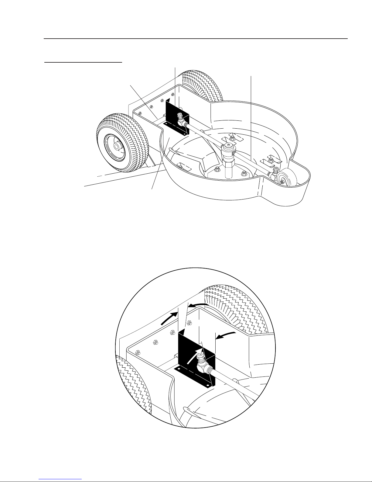
ALIGNMENT TOOL
Alignment
Tool
95-0728030
Axle
Plastic Body
STEP 1: Disconnect water to Cyclone, then turn
entire machine over to allow access to
nozzle jets.
Nozzle Arm
STEP 2: Place base of alignment tool flat against
bottom of Cyclone plastic body. Press end
of tool (opposite of desired angle) against
axle, then rotate nozzle arm to alignment
tool as shown.
STEP 3: Use either the 20° or the 15° end of tool, adjust nozzle to align with angled
surface of tool. NOTE: 20° is the factory setting. Nozzles can be set at 15° if a
slower rotational speed is desired.
Page 6

6
CYCLONE SYSTEM
EXPLODED VIEW
OPERATOR’S MANUAL
24
16
21
41
1
31
W
ARNING
ATENCION
ATTEN
TION
27
36
32
35
21
2
17
21
16
22
20
26
28
10
7
8
5
34
39
38
25
4
15
9
37
23
33
3
14
30
40
18
21
13
19
29
12
21
6
11
18
11
29
12
Page 7

CYCLONE SYSTEM
EXPLODED VIEW
PARTS LIST
OPERATOR’S MANUAL
7
ITEM PART NO. DESCRIPTION QTY
1 2-00260 Elbow, 1/4", Male Pipe 1
2 2-01080 Cap, Black Vinyl 4
3 2-011049 Base, Polyethylene, Red 1
4 2-0003 Nipple, 1/4" Close Sch 80 Steel 1
5 2-1104 Connector, 1/4" Anchor 1
6 2-11055 Swivel, Rotary Union URF400 1
7 2-11059 Swivel, 1/4" High Pressure 1
8 2-2003 Coupler, 3/8" Male Brass 1
9 2-4006 Guard, Splash 1
10 2-99071 Filter, High Pressure 1
2-990710 ▲ Screen, High Press Filter S/S 1
2-990711 ▲ Gasket, Nylon 1
11 4-0111320 Wand, 8" Rotary 2
12 4-01803015 Nozzle Only, SA, 1/8",
MEG-1503 2
13 4-0303 Wheel & Tire Assy, 4" w/Tube 2
14 4-031509 Wheel, Caster 3 Grey 1
15 81-21007L Valve, Acuator, Assy 1
16 90-10182 Bolt, 3/8" x 1-3/4", HH NC
Stainless 5
17 90-1042 Screw, 1/4" x 2" Carriage, ZN 4
18 90-20021 Nut, 3/8" Stainless, ESNA NC 8
19 90-20041 Collar, 5/8" Bore Shaft 3010 4
20 90-20054 Nut, Wing 1/4-20 ZN 4
21 90-40021 Washer, 3/8", SAE,
Stainless Steel 13
22 90-40089 Washer, Split-Lock 1/4" ZN 4
ITEM PART NO. DESCRIPTION QTY
23 95-0728018 Axle, 5/8" x 18.5", Stainless 1
24 95-0728022 Handle, Trigger Bar 1
25 95-0728023 Adapter, Valve, Trigger Bar 1
26 95-0728026 Handle, Lower Assy 2
27 95-0728027 Handle, Upper Assy 1
28 95-0728029 Plate, Backup, Splash Guard 1
29 2-10410 Elbow, 1/4" x 1/8", Brass,
90 Degree 2
30 95-0728025 Nipple, Bulkhead, 1/2" x 4-1/2",
304 SS, SCH. 40 1
31 4-02021234 Hose, 3/8" x 34" Pressure,
1/2" FJIC x 1/4" FNPT 1
32 2-00602 Elbow, 1/2" JIC x 1/2" FEM
90 DGR 1
33 90-020 Nut, 10/32" NF ST ST KEP 4
34 90-10141 Screw, 10/32" x 1/2" SHCS SS 4
35 90-10162 Bolt, 3/8" x 1" HH/NC, 316 SS 3
36 2-00301 Elbow, Street, 1/4" x 3/8", Steel 1
37 90-50035 Pin, Roll M2.5" x 24 mm
5395A277 1
38 90-1700 Screw, 8/32" x 1/4" SS,
SOL SET 1
39 90-50168 Hook, 10/24" x 2" 1
90-20044 ▲ Nut, 10/24" HEX, Whiz Loc
M/S Zinc 2
40 10-020310 Label, Warning 2
10-08014 ▲ Label, Made in USA 1
41 11-0477 Label, Cyclone 1
▲ Not Shown
Page 8

8
CYCLONE SYSTEM
OPERATOR’S MANUAL
TROUBLESHOOTING
MELBORPESUACELBISSOPNOITULOS
RELPUOCKCIUQ
gniR-OnroW.)1210-2#traP(gniR-OecalpeR
SKAEL
REHSAWERUSSERP
SELCYCREDAOLNU
YLBMESSAELZZON
dezisgnorwroretliferusserphgiH
rehsawerusserpdehcattarofselzzon
.eziselzzonkcehC
yltcerrocnidelgnaeraselzzoN.selzzontsujdaeR :ETON elgnaeroM
WOLSOOTGNINNIPS
.)s(elzzon,retliftuonaelcdnaevomeR
.°03tuobaotelgnA.noitatorretsafsnaem
TSAFOOTRO
GNINNIPSSELZZON
WOLSOOT
GNINAELCTON
ECAFRUS
bojrofllamsootrehsaw
dehcattarofemulovretawhguonetoN
selzzonetatorotrehsawerusserp
erusserpro,gnorwelgnaelzzoN
.rehsawerusserpregral
.rehsawerusserpmpgregraladeeN
othcattaroelgnaelzzonegnahC
NOZZLE CHART
Correct nozzle size is important for optimum cleaning efficiency. The Cyclone is shipped with two #3, 15° nozzles in rotary swivel. Review
correct nozzle size for your pressure washer. See chart below for correct nozzle size. To obtain the correct nozzle size in the rotary swivel, divide
the minimum nozzle size for the pressure by two. Round this figure up to the nearest half nozzle size. These are the 1/8" nozzles only (two
needed) for the rotary swivel on the Cyclone.
elzzoN
eziS
2430.02.23.05.17.77.08.98.0.11.12.14.16.17.19.10.2
3240.03.74.57.70.161.152.143.15.16.18.11.24.26.28.20.3
4250.04.36.00.104.106.107.108.10.22.25.28.21.35.38.30.4
5.4550.54.17.01.105.107.109.100.22.24.28.20.36.39.33.40.5
5750.05.97.03.108.109.101.202.25.28.21.36.30.44.47.40.5
5.560.55.78.04.109.101.203.205.28.234.38.34.48.42.55.5
6260.06.59.05.101.203.205.207.20.32.37.32.48.42.57.50.6
5.6460.56.00.107.103.205.207.209.23.36.30.46.42.57.50.6
7760.07.01.108.105.207.209.201.35.38.33.40.56.5
5.770.57.02.109.107.209.202.304.38.31.46.43.50.6
8270.08.03.100.208.201.304.306.30.44.40.56.5
5.8470.58.03.102.200.303.306.308.33.46.43.50.6
9670.09.04.103.202.305.308.300.45.40.55.5
5.9870.59.05.104.204.307.300.403.48.42358.5
0180.00.106.105.205.309.302.405.40.54.5
21780.02.109.100.302.406.400.504.50.6
51490.05.104.208.303.508.5
02901.00.202.300.5
03141.00.307.4
04651.00.4
ecifirO
04
.maid
).ni(
001
052
005
006
007
008
0001
0021
0051
0002
0052
0003
ISP
ISP
ISP
ISP
ISP
ISP
ISP
ISP
ISP
ISP
ISP
ISP
ISP
0053
ISP
0004
ISP
Page 9

CYCLONE SYSTEM
OPERATOR’S MANUAL
9
Cyclone System
WARRANTY
LIMITED MINIMUM 90 DAY WARRANTY
We warrant to the original consumer that each new part and accessory sold by C-Tech will be free from manufacturing defects
in materials or workmanship in normal service for the duration specified by the original component manufacturer with a 90 day
minimum from date of purchase, provided it is installed properly and the equipment is maintained in accordance with C-Tech's
instructions and manuals. Components manufactured by C-Tech, such as frames and handles, have a one year warranty from
date of purchase.
Our obligation under this warranty is expressly limited as to the replacement or repair, at our option, at C-Tech, Camas,
Washington 98607, or at a service facility designated by us, for such part or parts as inspection shall disclose to have been
defective.
EXCLUSIONS:
This warranty does not apply to defects caused by casualty or unreasonable use, including faulty repairs by others and
failure to provide reasonable and necessary maintenance.
THE FOLLOWING ITEMS ARE NOT COVERED BY THIS WARRANTY:
WE SHALL NOT BE LIABLE FOR SPECIAL, INDIRECT, INCIDENTAL, OR CONSEQUENTIAL DAMAGES OF ANY KIND,
including but not limited to labor costs or transportation charges in connection with the replacement or repair of defective parts.
ANY IMPLIED OR STATUTORY WARRANTIES, INCLUDING WARRANTY OF MERCHANTABILITY OR FITNESS FOR A
PARTICULAR PURPOSE, ARE EXPRESSLY LIMITED TO THE DURATION OF THIS WRITTEN WARRANTY. We make no
other express warranty, nor is anyone authorized to make any on our behalf.
Some states do not allow limitations on how long an implied warranty lasts or the exclusion or limitation of incidental or
consequential damages, so the above limitation or exclusion may not apply to you.
This warranty gives you specific legal rights and you may also have other rights which vary from state to state.
TO OBTAIN WARRANTY SERVICE:
Purchaser must bring the accessory parts to an authorized C-Tech Dealership. For the dealership nearest you write:
C-Tech, 4275 NW Pacific Rim Blvd, Camas, WA 98607.
Page 10

10
SYSTEME DE CHORRO DE AGUA
MANUAL DEL OPERADOR
INTRODUCCION
El Sistema de Cyclone de agua está diseñado para
adaptarse a una lavadora de presión haciendo rotar dos
boquillas de alta presión para producir el rociado y así
mismo determinar el tamaño del ancho de corte cuando
se limpian superficies de playas de estacionamiento,
pistas de acceso y veredas.
Responsabilidad del Dueño/Usuario
El dueño/usuario debe entender las instrucciones de
operación y las advertencias del fabricante antes de usar
el Sistema de Chorro de agua. La información de
advertencia debe ser enfatizada y entendida. Si el
operador no habla inglés, las instrucciones y
advertencias del fabricante deberán ser leídas y
discutidas en la lengua nativa del operador por el
comprador/dueño, asegurándose que el operador
entienda su contenido.
El dueño y/o usuario deben estudiar y mantener las
instrucciones del fabricante para futuras referencias.
Este manual deberá ser considerado como una
parte de la máquina y debe permanecer así en
caso que se revenda la unidad.
Cuando ordene repuestos, por favor especificar
el modelo y el número de serie.
SEGURIDAD DE LA MAQUINA
ADVERTENCIA
instrucciones puede causar unoperación defectuosa
e inadecua- da de la unidad y puede provocar la
muerte, causar heridas serias
y/o daños a la propiedad.
ADVERTENCIA
al equipo. Sea precavido al operar. No descargar el
flujo directamente en personas o animales ya que
puede causar heridas graves o la muerte.
ADVERTENCIA: Para reducir el
riesgo de accidentes, leer
cuidadosamente las instrucciones
de operación antes de usar la
unidad.
1. Leer cuidadosamente el
manual deldel operador. El
incumplimiento de las
ADVERTENCIA: El flujo de líquido
de alta presión del equipo puede
producir perforaciones en los
tejidos de la piel, causando heridas
graves.
2. La alta presión desarrollada por
estas unidades causará
accidentes personales o daños
3. Nunca hacer ajustes a la máquina mientras esté
operando.
4. Deben usarse accesorios de seguridad para los ojos
y protección de los pies cuando se use este equipo.
5. El mejor seguro contra un accidente es la precaución
y el conocimiento de la máquina.
6. Nunca diriga la varilla del chorro de agua a cualquier
parte de su cuerpo o alguna persona a 10 pies de
distancia ya que podría producir heridas graves.
ADVERTENCIA
8. El ensamble del Sistema de chorro de agua viene
equipado con una boquilla #6 en la pistola de
apagado y dos boquillas #3 en la placa giratoria.
Revise la boquilla de su equipo antes de usarlo.
9. No seremos responsable por cualquier cambio
hecho a nuestras unidades estándar o la aplicación
de cualquier otro componente no comprado de
nosotros.
10. La presió n NO debe exceder 4,000 PSI. La
temperatura NO debe exceder 200°F.
11. Para protegerla del congelamiento, apriete la
palanca del disparador después de apagar la
máquina para lavado a presión y después de haber
desconectado el tubo flexible de alta presión de
Cyclone. Esto permitirá que el agua desagüe a
través de los tubos flexibles.
ADVERTENCIA: El chorro de alta
presión puede ocasionar que trozos
de pintura y otras partículas vuelen
por los aires a altas velocidades.
7. Debe usarse ropa de seguridad
y protección para los ojos.
TECNICAS GENERALES
DE OPERACION
1. Desconectar la pistola de alta presión de la
manguera de alta presión. Estos artículos no se
incluyen, pero serán provistos cuando se requieran
acoplar a la lavadora de presión.
2. Conectar la boquilla hembra, incluída con la
lavadora, a la manguera de agua de alta presión.
NOTA: Recomendamos no usar manguera tipo
mar para prevenir que aparezcan marcas negras
en la superficie que se está limpiando.
3. Acoplar la manguera de alta presión de la lavadora
al Sistema de chorro de agua.
Page 11

SYSTEMA DE CHORRO DE AGUA
4. Inspeccionar el tamaño de la boquilla de la lavadora
de presión. El Sistema de chorro de agua viene con
dos boquillas #3. Si su lavador de presión requiere
una boquilla más grande que la #6, consulte con su
vendedor local.
NOTA: Para un lavado ideal, el Sistema de chorro
de agua debe adaptarse a un lavador de un mínimo
de 4 gpm y 3,000 psi de presión.
5. Prender el suministro de agua y arrancar la lavadora
de presión.
NOTA: Siempre es importante probar en una área
pequeña para la correcta regulación de la altura
necesaria de tal manera que la superficie a ser
limpiada no sea dañada.
6. Tirar del gatillo para que el agua empiece a limpiar
la superficie.
NOTA: Nunca deje de mover el Sistema de chorro
de agua mientras el gatillo está accionado y la
superficie está siendo limpiada o podrían ocurrir
daños en la superficie.
MANUAL DEL OPERADOR
11
Page 12

12
15°
20°
SYSTEME DE CHORRO DE AGUA
HERRAMIENTA DE ALINEAMIENTO
95-0728030
Herramienta de Ajuste
Eje
Carrocería Plástica
MANUAL DEL OPERADOR
Brazo de la
Tobera
PASO 1: Desconecte el agua de Cyclone, luego gire
la máquina completa para permitir el acceso
a las toberas de chorro.
PASO 2: Coloque la base de la herramienta de ajuste
plana contra la parte inferior de la carrocería
plástica de Cyclone. Presione el extremo de
la herramienta (opuesto al ángulo deseado)
contra el eje y luego gire el brazo de la tobera
hacia la herramienta de ajuste tal como se
muestra.
PASO 3: Utilizando el extremo de la herramienta en 20° o en 15°, ajuste la tobera para alinearla
con la superficie en ángulo de la herramienta. NOTA: 20° es ajuste de fábrica. Las
toberas se pueden fijar en 15° si desea una velocidad de rotación más despacio.
Page 13

Page 14

4275 N.W. Pacific Rim Blvd. • Camas, WA 98607 • (360) 833-1600
Form #97-6138 • Revised 10/01 • Printed in U.S.A.
 Loading...