

A GUIDE TO
Quantec
Approved Document No: DNSQ100101 Rev 6 • Page 1 of 16
a d d r e s s a b l e c a l l s y s t e m

WHAT IS QUANTEC? .......................................................................................................... 3
Overview .......................................................................................................................................... 3
Why have an addressable call system? .......................................................................................... 3
About this guide ............................................................................................................................. 3
SYSTEM OPERATION ......................................................................................................... 4
Standard calls .................................................................................................................................. 4
Call accept ........................................................................................................................................ 4
Staff presence .................................................................................................................................. 4
Call follower sounders (optional) .................................................................................................. 4
Reset ................................................................................................................................................. 4
Help required/assistance calls ........................................................................................................ 4
Emergency calls ............................................................................................................................... 4
Infrared staff attack calls (optional) ........................................................................................... 4/5
Day/Night mode .............................................................................................................................. 5
Automatic divert ............................................................................................................................. 5
Manual divert .................................................................................................................................. 5
Datalogging ..................................................................................................................................... 5
Paging .............................................................................................................................................. 5
NETWORK DEVICES ........................................................................................................... 6
Call points ........................................................................................................................................ 6
Monitoring points ........................................................................................................................... 6
Displays ............................................................................................................................................ 7
Infrared ceiling receivers ................................................................................................................ 7
Radio receivers ................................................................................................................................ 7
RF integrity transmitters ................................................................................................................. 7
Addressable overdoor lights/addressable sounders ..................................................................... 8
Quantec controller .......................................................................................................................... 8
ANCILLARY DEVICES ........................................................................................................ 9
Slave overdoor lights ...................................................................................................................... 9
Ceiling pulls ..................................................................................................................................... 9
Slave call points ............................................................................................................................... 9
Tail call buttons ..............................................................................................................
................. 9
Hand/foot operated pneumatic pads ............................................................................................ 9
Portable movement detectors .....................................................................................................10
Dual-action infrared/radio transmitters ...................................................................................... 10
Configurator for dual-action infrared/radio transmitters ......................................................... 10
PLANNING AN INSTALLATION ........................................................................................ 11
PLANNING THE WIRING .................................................................................................. 12
Example wiring overview ............................................................................................................. 13
DEVICE DIMENSIONS ...................................................................................................... 14
FURTHER INFORMATION ................................................................................................. 15
INDEX
Approved Document No: DNSQ100101 Rev 6 • Page 2 of 16

Quantec represents one of the biggest breakthroughs in call communication equipment for
many years. It is a powerful yet easy to use addressable call system that puts the needs of its
users (patients and staff) and the installer well and truly first.
The way the system operates can be tailored to suit a building’s exact requirements with
different day, night and call divert arrangements easily accommodated and, if required,
simply changed at a later date.
This flexibility, coupled with many other advanced features such as four different call levels
(plus an optional infrared staff attack facility), built-in datalogging and
full monitoring of all
network devices, makes Quantec the obvious choice for nursing homes, hospitals, health
centres, leisure centres, prisons, government buildings and many other private and public
sector establishments.
WHY HAVE AN ADDRESSABLE CALL SYSTEM?
As the type of establishments listed above have become larger and more specialised, demand
has increased for call systems that operate in more sophisticated ways, i.e. different urgencies of
calls, calls shown in different places at different times, sounders operating as quietly as possible,
etc. These requirements can vary greatly and although it is possible to meet some of these
demands with the careful planning of conventional call systems, conditions change and
there is often some special request which cannot be easily accommodated once installation
is complete.
The main advantage of addressable call systems over conventional systems is that they can
be installed with very little planning and displays can be fitted virtually anywhere to suit the
application. However, whilst simplifying things for the installer, some addressable systems
still fail to satisfy the varied needs of the user. This is because they are essentially ‘dumb’
systems, i.e. call points send notification of a call onto the wiring, displays pick the information up and the message is shown everywhere.
Quantec is different. It is much more sophisticated than basic addressable systems but at
the same time very easy for staff to use. Quantec’s call points send notification of a call to
the ‘Quantec Controller’ which passes the call only to pre-selected displays. What’s more,
should these arrangements need changing due to new working practices or alterations to
the building’s layout, they can be with the minimum of fuss.
In order to achieve this level of flexibility and allow the use of ordinary unscreened cable,
Quantec utilises a unique data protocol which works down just two wires (power and data).
This allows considerable cost savings on installation and means Quantec can be retrofitted
to the wiring of many existing conventional call systems. The protocol allows up to 256
addressable devices (displays, call points, infrared ceiling receivers, etc) to be connected to a
system together with virtually any number of ‘slave’ ancillary devices such as ceiling pulls
and overdoor lights.
ABOUT THIS GUIDE
This guide provides a detailed overview of how the Quantec Addressable Call System works.
It describes in simple terms the various Quantec devices that are available and provides
straightforward advice on how to plan and wire an installation. Further information, if
required, can be obtained from your distributor.
WHAT IS QUANTEC?
Approved Document No: DNSQ100101 Rev 6 • Page 3 of 16
SYSTEM OPERATION
CALL
RESET
Q
Q
A
V
V
Approved Document No: DNSQ100101 Rev 6 • Page 4 of 16
STANDARD CALLS
To trigger a call, the user presses the ‘CALL’ button on a wall-mounted
call point, pulls the cord of a ceiling pull unit or operates the remote
button of a tail call lead. This causes the call point’s confidence light to
pulse red slowly. Outside the room, sounders pulse slowly, overdoor lights
(if fitted) pulse red slowly and all relevant displays show the exact location
of the calling room.
CALL ACCEPT
When a call is shown on several displays at the same time,
several staff may respond simultaneously. To help prevent this
happening, a member of staff can accept the call at a display
by pressing its ‘A’ button. This will remove the call from all
displays (but for safety reasons the call will return if it is not dealt
with quickly).
STAFF PRESENCE
When the member of staff arrives, the call point’s ‘RESET’ button is pressed to cancel the
call and to put the call point into Staff Presence mode. This causes the call point’s confidence light to pulse green slowly. Outside the room overdoor lights (if fitted) pulse green
slowly and all relevant displays show the location of the room where staff are present.
CALL FOLLOWER SOUNDERS (optional)
If fitted, low level sounders will sound at all call points in Staff Presence mode when the
system is in NIGHT mode and a call occurs elsewhere. This helps reduce sound levels by
quietly informing staff that other calls are waiting, prompting them to visit a display.
RESET
As the member of staff leaves the room the call point’s ‘RESET’ button is pressed again to take
it out of Staff Presence mode and returning it to normal. If preferred, magnetic reset call
points can be used with magnetic reset keys (see CALL POINTS, page 6, for further details).
HELP REQUIRED (ASSISTANCE) CALLS
If assistance is required (but it is not an emergency), pressing the call point’s ‘CALL’ button
whilst it is in Standard Call or Staff Presence mode makes a Help Required call. This causes
the call point’s confidence light to pulse red more urgently than when a Standard call is
made. Outside the room, sounders pulse more urgently, overdoor lights (if fitted) pulse red
and a Help Required message appears on all relevant displays together with the location of
the room where assistance is required. Note: repeated operation of a tail call button or
ceiling pull will not initiate a Help Required call.
EMERGENCY CALLS
In an emergency, pressing the call point’s ‘CALL’ and ‘RESET’ buttons together makes an Emergency
call regardless of the previous state of the call point (unless in attack mode, see below). This
causes the call point’s confidence light to flash red and green. Outside the room, sounders pulse
rapidly, overdoor lights (if fitted) flash red and green and an emergency message appears on all
relevant displays together with the location of the calling room.
INFRARED STAFF ATTACK CALLS (optional)
To help combat the threat of verbal and physical abuse against
members of staff, Quantec has an optional infrared staff attack
facility which helps protect staff against disturbed patients,
intruders and/or aggressive visitors. It works as follows:-

Designated staff carry an infrared transmitter which they attach to their uniforms. When an
attack takes place, they activate the transmitter by pressing one of its buttons or releasing
its retained pull clip to fill the area with infrared signals (QT412RXA transmitters only).
These signals are received by a special infrared call point or ceiling receiver which instantly
informs Quantec that an attack is taking place. An urgent, piercing alarm is sounded
throughout the building (as programmed) and the exact location of the attack is indicated
at all relevant displays, thus prompting the quick response of security staff.
For security reasons Attack calls can only be reset by entering a special code at the
Quantec Controller or a Display with controls.
In addition to Attack calls, Quantec’s infrared call points and ceiling receivers can generate other
levels of call too. The type of call generated depends on the type of transmitter(s) and receiver(s) used
(see pages 6, 7 and 10 for further details on infrared call points, ceiling receivers and transmitters).
All QT412 range transmitters have the ability to send radio as well as infrared calls. To
generate a radio call, at least one Quantec radio receiver is required (see page 7 for details).
Radio receivers are ideal for picking up calls in outside areas such as car parks and loading
bays where infrared transmission is not practical.
DAY/NIGHT MODE
Night mode can be manually selected by the user or, if preferred, the commissioning
engineer can allocate times at which the system will automatically enter and exit night
mode. When in night mode, all calls are shown on all displays but only selected displays
sound. This allows for lower staffing levels and reduced sound levels. Night mode can be
backed up by the use of optional CALL FOLLOWER SOUNDERS in call points (see page 4).
AUTOMATIC DIVERT
If a call remains unanswered for a preset time (1-8 mins), to ensure it does not remain
unattended indefinitely, the system can be set up to automatically divert it to other areas.
MANUAL DIVERT
If a member of staff leaves one area they can divert calls to another area via the controls on
a display.
DATALOGGING
Quantec’s built-in datalogger can record the date, time, type and location of every call and
reset for output to an 80 column serial printer. Quantec Printer Kits (part no. QT600P) are
available and include a printer, interface lead and connection socket. All kits are tested and
calibrated with Quantec prior to despatch.
PAGING (optional)
Due to problems of misuse (pagers being dropped in the sluice, etc), we recommend the use of
CALL FOLLOWER SOUNDERS and a larger number of displays as a reliable, practical alternative
to paging. However, when paging must be used, the following options are available:
Tone Only Paging: a basic paging facility designed to indicate that a call has been raised.
No priority is given to the level of incoming call, i.e. if a standard call is flagged before an
emergency call, the pager will not show the emergency call until the standard call clears.
Standard calls beep once and the number 1 is shown, Help Required calls beep twice and
the number 2 is shown, Emergency and Attack calls beep three times and the number 3 is
shown. To determine the exact location of a call, staff must visit a display.
Alphanumeric Radio Paging: this option allows call information from the Controller to be
broadcast globally to alphanumeric pagers via a radio transmitter. It is possible to select
which type of call(s) are transmitted to the pagers (i.e. emergency calls only) but different
levels of calls
cannot be prioritised. For example, if a standard call is triggered followed by
an emergency call, the emergency call will not be displayed until the standard call has been
accepted. (This is not the case at displays where different types of calls are still prioritised).
Approved Document No: DNSQ100101 Rev 6 • Page 5 of 16

Quantec’s network devices are small, discreet and designed to blend into any sort of decor.
Up to 256 network devices can be used per system, each containing a non-volatile memory to
store its unique address identification number. Network devices consist of Call Points, Displays,
Monitoring Points, Infrared Ceiling Receivers, Radio Receivers and Addressable Overdoor
Lights. They do not include ancillary devices such as Slave Overdoor Lights or Ceiling Pulls.
CALL POINTS
Quantec’s call points have two buttons, a red/green confidence light and
(depending on the version purchased) a remote socket for connecting
ancillary devices such as tail call leads and pressure pads. The type of call
point used will depend on the type of operation (button or magnetic
reset) and the system features you wish to take advantage of. For example,
if you wish to utilise Quantec’s Call Follower Sounder option, call points
with sounders should be used. Likewise, if you want to make calls with
infrared transmitters, call points with infrared receivers should be used.
Note: infrared coverage may not be required in all rooms and infrared ceiling receivers are
also available.
QT602 Range Call Points (include remote sockets)
QT602 .................. Quantec call point, button reset
QT602S ................. Quantec call point, button reset with sounder
QT602R ................ Quantec call point, button reset with I/R receiver
QT602RS .............. Quantec call point, button reset with sounder & I/R receiver
QT602M ............... Quantec call point, magnetic reset
QT602SM ............. Quantec call point, magnetic reset with sounder
QT602RM ............. Quantec call point, magnetic reset with I/R receiver
QT602RSM ........... Quantec call point, magnetic reset with sounder & I/R receiver
QT609 Range Call Points (do not include remote sockets)
QT609 .................. Quantec call point, button reset
QT609S ................. Quantec call point, button reset with sounder
QT609R ................ Quantec call point, button reset with I/R receiver
QT609RS .............. Quantec call point, button reset with sounder & I/R receiver
QT609M ............... Quantec call point, magnetic reset
QT609SM ............. Quantec call point, magnetic reset with sounder
QT609RM ............. Quantec call point, magnetic reset with I/R receiver
QT609RSM ........... Quantec call point, magnetic reset with sounder & I/R receiver
Magnetic Reset Keys
NC803M/10 .......... Pack of 10 magnetic reset keys
NC803M/50 .......... Pack of 50 magnetic reset keys
MONITORING POINTS
Monitoring points have one button, a red/green confidence
light and an isolation keyswitch to prevent operation when a door
is to be left open. If required, fire exits, doorbells, telephones, drug
cupboards, etc, can be connected so that operating them makes a
standard or emergency call. Door contacts are not supplied.
QT604 .................. Quantec Monitoring Point, button reset
QT604M ............... Quantec Monitoring Point, magnetic reset
NETWORK DEVICES
CALL
RESET
Q
RESET
ON
ISOLATED
Q
Approved Document No: DNSQ100101 Rev 6 • Page 6 of 16

Q
A
V
V
Approved Document No: DNSQ100101 Rev 6 • Page 7 of 16
DISPLAYS
Quantec’s displays scroll automatically and only show the calls
which are the most urgent plus a message saying how many calls
are waiting on that part of the system. Therefore, if there are
no calls, the displays will show the time, then Staff Presence calls,
Standard calls, Help Required calls, Emergency calls & Attack calls.
They have an A (accept) button, plus buttons to control divert
and other features. Displays with no controls are also available.
QT608C ................ Quantec Corridor Display, with controls
QT608CD ............. Quantec Corridor Display, no controls
INFRARED CEILING RECEIVERS
Infrared ceiling receivers are designed for use with Quantec’s wide range of
infrared transmitters (see page 10). They are usually located in bedrooms,
corridors, common rooms and any other internal area that requires infrared
coverage. Slave infrared ceiling receivers are also available (up to three per
master infrared ceiling receiver or infrared call point) to improve coverage in
‘L’ shaped rooms, etc. Dependent on the type of transmitter(s) used, master
ceiling receivers allow standard and/or attack calls to be made (both levels of
call can be reset by entering a special code at the Quantec Controller or a corridor display). The
type of calls that can be made from a slave ceiling receiver will depend on whether they are
connected to a master ceiling receiver (standard and attack calls only) or an infrared call point
(standard, help required, emergency and/or attack calls).
QT302RX .............. Master Infrared Ceiling Receiver
QT302RXS ............Slave Infrared Ceiling Receiver
QT302RT .............. Test Infrared Ceiling Receiver
RADIO RECEIVERS
Radio receivers are designed for use with Quantec’s QT412 range of
dual action infrared/radio transmitters (see page 10). Dependent on
the transmitter(s) used, they allow standard and/or attack calls to be made
from external areas such as car parks, loading bays, etc.,
(both levels of call can
be reset by entering a special code at the Quantec Controller or a corridor display)
. Receivers
must be mounted internally - typically in a building’s roofspace - where they can provide RF
coverage of typically 60m (dependent on conditions/location). An optional RF extension aerial is
available for outdoor use and we recommend this for sites where the receiver is located close to
large metallic objects or thick structural walls. In some cases external aerials can increase a
receiver’s RF coverage to typically 90m. For areas such as large car parks, it is not uncommon for
multiple radio receivers to be used (for example, on adjacent walls) to ensure sufficient coverage.
For sites with multiple, separately-managed areas, different radio receivers can be set up to respond
to calls from certain transmitters only. This is done via an RF grouping facility whereby a receiver
in, say, RF group 3, will only respond to transmitters assigned to the same RF group. The default
setting for all radio receivers and transmitters is RF group 1 (of 16)
.
To help ensure the integrity of Quantec radio receivers, we recommend at
least one monitored RF Integrity Transmitter is used with every radio
receiver. Supplied on a single gang plate, they work by sending a periodic
test transmission to the radio receiver. If the receiver fails to receive the test
signal, it sends a fault message to the Quantec Controller to advise that
something is wrong.
QT422RX .............. Quantec Radio Receiver
QT422RXEX ......... External Extension Aerial for Quantec Radio Receiver
QT421 .................. RF Integrity Transmitter
Q
RF Integrity Transmitter

ADDRESSABLE OVERDOOR LIGHTS & ADDRESSABLE SOUNDERS
Addressable overdoor lights are designed to act as area
indicators or to provide ‘follow me’ lights at the ends of
corridors, etc. They have built-in sounders and are
similar in appearance to standard overdoor lights.
Because they are addressable, they can be instructed to
light when certain groups of call points are calling.
Addressable sounders can be used to increase sound
levels in long corridors, outside communal areas, etc.
QT606A ................ Quantec Addressable Overdoor Light
QT688 .................. Quantec Addressable Sounder
QUANTEC CONTROLLER
The Quantec Controller supplies power to
and controls the Quantec system. It
constantly monitors all network devices
and indicates the exact ID number of any
faulty devices. Connections are provided
at the controller for all network wiring,
optional stand-by batteries and various
system ancillaries including printing,
paging and programming equipment. It is
supplied in a 410 x 250 x 80mm metal back
box and can be flush or semi-flush
mounted using the AFP385 mounting bezel.
Programming is usually carried out via a laptop PC running Quantec’s upload/download PC
software (part no. QT707). The buttons on the controller’s front can also be used for programming
but as this is very time consuming we recommend it for updating existing site data only.
In addition to the controller’s library of 45 pre-set place names, up to 40 custom place
names (of up to 11 characters) can be programmed into the Controller for assigning to
network devices. The library of 45 pre-set names consists of the following:-
Annex; Area; Bathroom; Bedroom; Conservatory; Corridor; Dining room; Disabled WC; Display;
Door; Doorbell; Drugs Cab; Entrance; ESMI Unit; Exit; Fire exit; Flat; Floor; Gents WC; Hairdresser; Kitchen; Ladies WC; Laundry; Lift; Lounge; Meeting RM; OD Light; Phone; Quiet Room;
Reception; Room; Shower; Sluice; Special; Staff Room; Toilet; Treat Room; TV Room; Ward; Zone
Up to four alphanumeric characters can be tagged onto the end of all pre-set and custom
place names, a typical example being: “DISABLED WC EW01”.
The Controller’s 40x2 character display is effectively split into two parts, the left side
showing the time, date and call information; the right side continually showing the overall
status of the system and providing notification of any faults.
To assist the engineer at system setup and during routine maintenance, a wide range of
installation and fault finding functions are also provided at the Controller. These are
described in greater detail in the Quantec Programming Manual
(doc. no. DNU6012001)
QT601-2 ............... Quantec Controller
AFP385 ................. Bezel for QT601-2 Quantec Controller
QT707 .................. Quantec Programming Kit (incl. upload/download software & lead)
QT600P ................ Quantec Printer Kit (incl.pre-tested printer, wall socket and lead)
DP874QA ............. 400m Alphanumeric paging transmitter (incl. transmitter,wall socket & lead)
DP877QA ............. 32 character alphanumeric display pager, group A.
Please refer to our Quantec price list for additional alphanumeric paging equipment such as
extension aerials, mounting brackets and low loss cable.
V
Quantec
V
V
A
1
2
3
E
Controller
✓
✕
Approved Document No: DNSQ100101 Rev 6 • Page 8 of 16

SLAVE OVERDOOR LIGHTS
Slave overdoor lights comprise two red and two green ultra-bright LEDs
inside a triangular diffuser. They offer low current consumption and
connect to call points via four cores (Two cores are the same as the two
network wires so connection to the network can be made at the
overdoor light or the call point).
QT606 .................. Quantec Overdoor Light
CEILING PULLS
Ceiling pulls have a red confidence light and a 3m cord with
two open-sided triangular pulls specially designed for ease of
use by the infirm. Four knockouts are provided for 16mm square
mini trunking and the backplate fits BESA centres. They
are generally reset at a call point to which they connect via
three cores.
QT607 .................. Quantec Ceiling Pull
SLAVE CALL POINTS
Slave call points are functionally the same as ceiling pulls and as such must
be used in conjunction with a master call point. Comprising a call button,
remote socket and confidence light, they are designed for use in areas
such as double bedrooms where more than one call button may be
required. All calls must be reset at the master.
QT602D ................ Quantec Slave Call Point
TAIL CALL BUTTONS
Tail call buttons consist of a pear-shaped push, a lead and a plug
that connects it to a call point’s remote socket. A call is made by
pressing the button or by pulling the plug out. Tail call leads are
available in a variety of different lengths (as indicated below) to
suit different applications.
NC805C/6 ............. 1.8m (6ft) tail call button with right angle plug
NC805C/14 ........... 4.2m (14ft) tail call button with right angle plug
NC805D ................ 1.2-3.6m (4-12ft) tail call button with coiled lead
HAND/FOOT OPERATED PNEUMATIC PADS
Ideal for patients who find it difficult to press buttons,
Quantec’s hand/foot operated pneumatic pad must be
used in conjunction with the NC805AS air switch.
Applying pressure to the pad operates the air switch
which, when connected to a call point’s remote socket,
triggers a call.
NC805P ................ Hand/Foot Operated Pneumatic Pad
NC805AS ..............Remote Air Switch, for use with NC805P
ANCILLARY DEVICES
CALL
Q
Approved Document No: DNSQ100101 Rev 6 • Page 9 of 16

PORTABLE MOVEMENT DETECTORS
A simple to operate adjustable weight sensor which sits under the
leg of a bed and connects to a call point’s remote socket via a
jack plug. A call is triggered when the bed is vacated, thus
alerting staff to the prospect of a wandering patient.
NC805MD ............ Portable Movement Detector
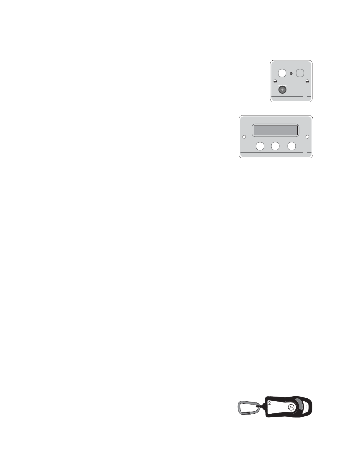
DUAL-ACTION INFRARED/RADIO TRANSMITTERS
Quantec’s new QT412 range of rechargeable dual-action
infrared/radio transmitters have a typical infrared
transmitting range of 10m (line of sight) and a typical
radio transmitting range of around 60m.
Each transmitter has two infrared emitters (one on each side to maximise performance), two
buttons (A & B) and a retained ‘pull clip’. Depending on its configuration, pressing a
transmitter’s buttons or activating its ‘pull clip’ will generate a standard, help required,
emergency or staff attack call on a compatible Quantec infrared and/or radio receiver.
Housed in a tough plastic enclosure, each transmitter provides battery low indication as
standard and can be recharged fully in approximately 14 hours using the QT424/1 single way
charging unit. A ten way charging unit, the QT424/10, is also available for sites with multiple
transmitters.
Two pre-configured transmitters are available, the QT412RXA push for attack/pull for attack
transmitter and the QT412RXCA push for call/pull for attack transmitter. If a different
transmitter configuration is required, the QT423 configurator (described below) will allow an
engineer to reprogram any of the above transmitters to suit the operational requirements of
an individual site.
QT412RXA ........... Dual action infrared/radio transmitter
(configured for push for attack/pull for attack)
QT412RXCA .........Dual action infrared/radio transmitter
(configured for push for call/pull for attack)
QT424/1 ............... Single way battery charging unit for QT412 range transmitters
QT424/10 ............. Ten way battery charging unit for QT412 range transmitters
CONFIGURATOR FOR QT412 RANGE DUAL-ACTION TRANSMITTERS
The QT423 configurator allows the operation of any QT412 range transmitter
to be tailored to suit the requirements of a specific site. In particular it allows
authorised engineers to :-
• Assign the level of call that will be triggered when the transmitter’s A button is pressed.
• Assign the level of call that will be triggered when the transmitter’s B button is pressed.
• Assign the level of call that will be triggered when the transmitter’s ‘pull clip’ is activated.
• Set the transmitter’s A & B buttons so they only trigger a call when both are pressed simultaneously.
• Turn the transmitter’s on-board ‘confidence’ beeper on or off.
• Turn the transmitter’s radio action off.
• Set the transmitter’s transmission time to run continuously or to automatically switch off after a
pre-determined time .
• Assign the transmitter an RF group ID address (1 to 16) to match the setup of any Quantec radio
receivers on the system - see RADIO RECEIVERS, page 7, for further details.
• Change the transmitter’s mode of infrared transmission to ‘pulsed’ to suit older Quantec systems.
Each configurator comes with a programming CD (Windows 2000/XP compatible), a USB
connection lead (to connect the configurator to a PC) and a lead for connecting the
configurator to a QT412 range transmitter for programming.
QT423 .................. Quantec Configurator
Approved Document No: DNSQ100101 Rev 6 • Page 10 of 16
Configurator
USB
Device

Although Quantec far exceeds the minimum requirements of all agencies, rules regarding
installation may vary depending on the area of the country. If there is any doubt, please
check with the relevant authorities/building management.
The Quantec Controller can be located anywhere on the network although it is usually
installed centrally to reduce wiring runs or in the manager/matron’s office. When not being
used for programming, it operates in exactly the same way as a display.
Displays should be located strategically around the premises where they can be readily seen by
staff, in areas such as junctions in corridors, staff rooms, etc.
In nursing home/hospital type applications, Call Points should be sited next to each bed
(preferably above bedhead height to avoid damage to them when the bed is moved) and in
lounges, dining rooms and other communal areas. In other applications such as leisure centres,
prisons, etc, they should be installed as advised by the client.
Ceiling Pulls should be fitted in each bathroom and WC.
Slave Overdoor Lights (if required) are normally installed outside rooms.
If area indication or ‘follow me’ lights are required, Addressable Overdoor Lights should be
positioned at the ends of corridors, above fire doors, etc.
Monitoring Points should be fitted close to fire exits, drug cupboards or alongside any other
area/device which needs to be monitored.
Infrared Ceiling Receivers/Call Points should be positioned in all areas which require infrared
coverage. The number and type of devices used will vary depending on the application. Note
that master infrared ceiling receivers can generate standard and/or attack calls only whereas
infrared call points can generate standard, help required, emergency and/or attack calls. Slave
ceiling receivers will generate the same levels of call as the master device they are connected to.
When deciding on the position of
Infrared Ceiling Receivers
, take into account the 10 metres
line-of-sight transmitting range of infrared transmitters. Use slave receivers in large open
areas, long corridors or ‘L’ shaped rooms where one master is unable to provide sufficient
coverage. Where possible, position master receivers in central positions and look at the
relevant sight lines. If any area of the room is out of sight of the receiver or is over 7 metres
away from it, boost coverage with slave rece
ivers. If in doubt, use slaves (up to three slaves
can be used per master).
As Infrared Call Points are designed to be wall-mounted, pay particular attention to their
height as furniture or ornaments added to the room at a later date could obstruct them. As
with master infrared ceiling receivers, up to three slave receivers can be connected to one
master infrared call point.
Note that different types of lighting and wallcovering can affect the range of infrared
transmissions and rooms with excessively dark walls may require more infrared receivers than
rooms with reflective walls. Avoid placing receivers in direct sunlight. (Remember, when
surveying rooms that the sun’s position changes and a room that is in the shade in the
morning may not be in the shade in the afternoon). Watch out for corridors with lots of
windows, conservatories and rooms with skylights - you may have to increase the number of
receivers used to compensate for this. Also, avoid placing receivers too close to fluorescent
lights and spot lights and be careful not to position them too close to smoke detectors,
lampshades or PA speakers as these may obstruct any signals transmitted.
Radio Receivers should be mounted internally - typically in a building’s roofspace - close to
the area that requires RF coverage. Typical coverage (dependent on conditions) is around
60m per receiver, boostable to 90m if an external RF aerial is used. See Radio Receivers,
page 7, for more detailed information.
PLANNING AN INSTALLATION
Approved Document No: DNSQ100101 Rev 6 • Page 11 of 16

Quantec can be compared to an analogue addressable fire alarm system where the integrity
of the wiring is of paramount importance. However, with Quantec, a ‘star’ rather than a
‘loop’ wiring scheme is used.
In order to allow the use of ordinary unscreened cables and reduce the risk of volt drop, the
only method of wiring Quantec we recommend involves the use of ‘network splitters’ (QT603).
Network splitters have six fused ‘limbs’ for the wiring of individual sections of the system
and they provide a convenient way of wiring, testing and protecting the system. In
addition to simplifying the wiring and reducing volt drop, their fault and power LEDs also
help find installation faults.
Each splitter has one input and one output network connection (both unfused) and six
'limb' outputs that are fused. The unfused connections are for the connection of the
network ‘Spine’ which should normally be wired in at least 1mm
2
cable (e.g. T&E). No other
networked devices should be connected to the spine except network splitters. The fused
outputs i.e.‘Limbs’ are for the connection of individual circuits containing networked
devices. These should be wired in four or six core security cable. In excess of 60 addressable
devices can be connected to each network splitter. Consequently four splitters are capable
of accommodating an entire system. However, for larger systems and for convenience it is
likely that more will be used.
As network devices are ‘soft addressed’ after installation no consideration need be made as
to how different network devices will interact with each other. Within rooms, however,
ancillary devices must be connected to a call point and it is simplest to loop in and out of
slave overdoor lights (if fitted). If slave overdoor lights are not fitted, loop in and out of
call points. The diagrams below show how this should be done in nursing home-type
applications, but the same applies to other buildings too.
PLANNING THE WIRING
SLAVE
OVERDOOR
LIGHT
CALL
POINT
CEILING
PULL
CALL
POINT
CEILING
PULL
DEVICE WIRING
WHEN SLAVE
OVERDOOR LIGHTS
ARE USED
DEVICE WIRING
WHEN SLAVE
OVERDOOR LIGHTS
ARE NOT USED
2
2
4
4
4
2
2
FROM SPLITTER
FROM SPLITTER
Comprehensive details on how to wire Quantec appear in our Quantec Wiring Instructions
(doc. no. DNUQ171717)
. Please ensure your contractor obtains a copy and reads it carefully before
work commences. Pre-Commissioning Instructions are also available (doc. no.
DNUQ1818PRE)
.
Approved Document No: DNSQ100101 Rev 6 • Page 12 of 16

Approved Document No: DNSQ100101 Rev 6 • Page 13 of 16
EXAMPLE WIRING OVERVIEW
QT601-2
QT606
QT604
door
contacts
QT422RX
QT421QT608C
QT609
QT603
to next
QT603
QT603 QT606QT602QT602
QT602 QT602D
QT608C
QT608C
Max. 3 x QT602Ds
per master call point,
ceiling receiver or
monitoring point
Max. 3 x QT607s
per master call point
QT606A
Max. 32 x
QT606As
per system
QT606 QT602 QT607 QT607
QT302RXQT302RXS
SPINE
100m = 1.0mm2 twin and earth
150m = 1.5mm
2
twin and earth
250m = 2.5mm
2
twin and earth
LIMB
40m = 4 core stranded alarm cable
60m = 8 core stranded alarm cable
Max. 3 x
QT302RXs
per master
ceiling
receiver
A maximum of 10 network
devices can be connected to
each of the QT603s 6 outputs
240V a.c.
QT600P Printer Kit
(wall socket, lead & pre-tested printer)
QT600S Wall socket
QT601-2 Quantec controller
QT602 Master call point (with remote)
QT603 Network splitter
QT604 Monitoring point
QT609 Master call point (no remote)
QT606 Slave overdoor light
QT606A Addressable overdoor light
QT606
QT607 Ceiling pull
QT608C Display
QT302RX Master ceiling receiver
QT302RXS Slave ceiling receiver
QT421 Radio ‘heartbeat’ plate
QT422RX Radio receiver
QT412RXA Dual action transmitter
Other devices are available
DP874QA Radio Paging Transmitter
(wall socket, lead & transmitter)
Programming
PC

Width Height Depth
Call points/monitoring points 87mm 87mm 35mm
Infrared ceiling receivers 87mm 87mm 35mm
Overdoor lights (addressable and slave) 87mm 87mm 60mm
RF integrity transmitter plate 87mm 87mm 25mm
Displays/network splitters 146mm 87mm 35mm
Ceiling pulls 93
Ømm - 27mm
Infrared transmitters (main body) 45mm 115mm 25mm
Portable movement detectors 100mm 48mm 187mm
Pressure pads 93
Ømm - 22mm
Quantec controller (back box) 410mm 250mm 80mm
Quantec controller (lid) 439mm 274mm 7mm
Radio receivers 271mm 155mm 170mm
All single gang devices (87mm x 87mm) mount on 25mm single gang UK back boxes.
All double gang devices (146mm x 87mm) mount on 35mm double gang UK back boxes.
Quantec Controllers are designed to be surface mounted or, alternatively, semi-flush
mounted using the AFP385 bezel.
Radio receivers are designed to be surface mounted.
Ceiling pulls have four knockouts for 16mm square mini trunking and their backplate fits
BESA centres.
All quoted dimensions are approximate.
DEVICE DIMENSIONS
Approved Document No: DNSQ100101 Rev 6 • Page 14 of 16

Approved Document No: DNSQ100101 Rev 6 • Page 15 of 16
Want to know more? Why not enquire about our free Quantec training courses?
Intended primarily for those working in engineering and sales, these intensive courses are
designed to offer an in-depth understanding of the installation, maintenance and
commissioning of the Quantec addressable call system.
Held regularly at the manufacturer’s headquarters in the north west of England, each
course lasts approximately four to five hours.
Please note that off-site training sessions can also be arranged for qualifying customers
(minimum 6 delegates). Please contact your distributor for details.
FURTHER INFORMATION

Approved Document No: DNSQ100101 Rev 6 • Page 16 of 16
C-TEC, Stephens Way, Wigan WN3 6PH. United Kingdom.
© 1996-2005. Approved Document No: DNSQ100101 Rev 6. We reserve the right to alter product specifications
at our discretion and without prior notice. Errors and omissions excepted. This guide has been carefully
checked prior to publication. However, no responsibility can be accepted by the Manufacturer or Distributor(s)
of the Quantec system for any inaccuracies or for any misinterpretation of an instruction or guidance note.
UK Sales: Tel: 01942 322744
Fax: 01942 829867
E-Mail: sales@c-tec.co.uk
European Sales: Tel: +44 1942 322744
Fax: +44 1942 829867
E-Mail: eu.exports@c-tec.co.uk
Export Sales: Tel: +44 161 257 2541
Fax: +44 161 225 8817
E-Mail: xportsales@xportsales.com
Website: www.c-tec.co.uk
 Loading...