

Page 1

USER MANUAL
SVP Express
An Intelligent Surveillance System
CTC Uni
on Technologies Co.,
Ltd
.
Page 2

Page 3

1
LEGAL
The information in this publication has been carefully checked and is believed to be entirely
accurate at the time of publication. CTC Union Technologies assumes no responsibility , however,
for possible errors or omissions, or for any consequences resulting from the use of the
information contained herein. CTC Union Technologies reserves the right to make changes in its
products or product specifications with the intent to improve function or design at any time and
without notice and is not required to update this documentation to reflect such changes.
CTC Union Technologies makes no warranty, representation, or guarantee regarding the
suitability of its products for any particular purpose, nor does CTC Union assume any liability
arising out of the application or use of any product and specifically disclaims any and all liability,
including without limitation any consequential or incidental damages.
CTC Union products are not designed, intended, or authorized for use in systems or applications
intended to support or sustain life, or for any other application in which the failure of the product
could create a situation where personal injury or death may occur. Should the Buyer purchase or
use a CTC Union product for any such unintended or unauthorized application, the Buyer shall
indemnify and hold CTC Union Technologies and its officers, employees, subsidiaries, affiliates,
and distributors harmless against all claims, costs, damages, expenses, and reasonable attorney
fees arising out of, either directly or indirectly, any claim of personal injury or death that may be
associated with such unintended or unauthorized use, even if such claim alleges that CTC Union
Technologies was negligent regarding the design or manufacture of said product.
TRADEMARKS
Microsoft is a registered trademark of Microsoft Corp.
HyperTerminal™ is a registered trademark of Hilgraeve Inc.
User Manual
Version 1.0 Oct 2007 First Release
This manual supports the following:
SVP-Express
This document is the first official release manual. Please check CTC Union's website for any
updated manual or contact us by E-mail at [email protected]. Please address any comments for
improving this manual or to point out omissions or errors to [email protected]. Thank you.
CTC Union maintains a support web site (support.ctcu.com) where you may obtain the latest
manual, quick installation guide, and operational firmware. Membership to this web site is free,
however, you must be a registered member in order to access any software updates.
CTC Union Technologies Co., Ltd.
2008 Copyright, All rights reserved.
Page 4

2
BEFORE USING THIS PRODUCT
This CTC Union product has been designed with safety in mind. However, if not used properly,
electrical products can cause fires which may lead to serious bodily injury. To avoid such
accidents, be sure to heed the following.
Legal Caution:
Video and audio surveillance may be forbidden by laws that vary from country to country. Please
check the laws in your local region before using this product for surveillance purposes.
Heed the safety precautions
Be sure to follow the general safety precautions and the “Operation Notice.”
In case of a breakdown
In case of system breakdown, discontinue use and contact your authorized CTC Union dealer.
In case of abnormal operation
• If the unit emits smoke or an unusual smell,
• If water or other foreign objects enter the cabinet, or
• If you drop the unit or damage the cabinet:
1 Disconnect the cable and the connecting cables.
2 Contact your authorized CTC Union dealer or the store where you purchased the product.
Operation Notice - Operating or storage location
Avoid operating or storing this unit in the following locations:
• Extremely hot or cold places (Operating temperature: 0 °C to +50 °C [32 °F to 122°F])
• Exposed to direct sunlight for a long time, or close to heating equipment (e.g., near heaters)
• Close to sources of strong magnetism
• Close to sources of powerful electromagnetic radiation, such as radios or TV transmitters
• Locations subject to strong vibration or shock
Ventilation
To prevent heat buildup, do not block air circulation around the device.
Transportation
When transporting the unit, repack it in its original packaging or in materials of equal quality.
Cleaning
• Use a soft, dry cloth to clean the external surfaces of the device. Stubborn stains can be
removed using a soft cloth dampened with a small quantity of detergent solution, then wipe dry.
• Do not use volatile solvents such as alcohol, benzene or thinners as they may damage the
surface.
Page 5

Contents
A. Getting Started 1
A.1. Main Function 1
A.2. System Requirement 1
A.2.1. Client-Server System Structure 1
B. Running the Installation Wizard 3
B.1. SVP Express Server version – Installing 3
B.2. SVP Express Client version – Installing 7
B.3. Firewall Configuration 7
C. Control Program 7
C.1. Automatically starts upon system boot up 7
C.2. Shutting Down the Control Program 8
C.3. Start the Control program manually 8
D. Admin Program 9
D.1. Running the Admin Program 9
D.2. Admin Interface Overview 10
D.3. System Management Overview 10
D.3.1. Email Setting 11
D.3.2. Holiday Setting 12
D.3.3. DNS Setting 12
D.3.4. Storage 13
D.3.5. System Alarm 15
D.3.6. Rotation 16
D.3.7. Motion Rectangle 16
D.4. User Group 17
D.4.1. User 17
D.4.2. Group 19
D.5. Area and eMap management 21
D.5.1. Add Area 23
D.5.2. Remove SubArea 23
D.5.3. Rename the Area 23
D.5.4. Remove Area 24
D.5.5. Upload eMap 24
D.5.6. Refresh eMap 24
D.5.7. Resize eMap Icon 25
D.5.8. Device Management (Network Camera, Video Server Controller) 25
D.5.8.1. Network Camera 26
Page 6

D.5.8.1.1. Network Camera Button Overview 26
D.5.8.1.2. Network Camera Setting Overview 27
D.5.8.1.3. Remove Network Camera 34
D.5.8.1.4. HW Password 34
D.5.8.1.5. Sensor (Digital Input) 35
D.5.8.1.6. Relay (Digital Output) 36
D.5.8.2. Video Server 37
D.5.8.3. Tools in Menu Bar of eMap interface 38
E. Monitor Program 39
E.1. Running Monitor Program 39
E.2. Monitor Program Interface 40
E.3. Video Display Area 40
E.4. Camera Selection 41
E.5. Display Selection 41
E.5. Local Video Setting 41
E.5.1. Local Record 41
E.5.2. Local Play 42
E.5.3. Local Folder 43
E.5.4. Snapshot 43
E.5.5. Resolution switch while Single camera (CIF/4CIF) 43
E.6. PT Control Interface 43
E.7. System Setting 44
E.7.1. Relay Setting/Cancel Alarm 44
E.7.2. Server Query 45
E.7.3. Alarm On/Off 45
E.7.4. Alarm Query 46
E.7.5. Exit 46
E.8. Alarm eMap 46
E.9. Alarm Notification Log 47
Page 7
Page 1
A. Getting Started
For a better understanding, please read this manual before operate the SVP Express system.
A.1. Main Function
SVP Express includes the following programs:
1. Control: This program manages video recording, input/output events and alarm triggering; it is
running as a background program of SVP Express comes with PC boot up. For detail please
refer to Section C.
2. Admin: This program allows you to configure the system of SVP Express and setup the device
which connected to system, for detail, please refer to Section D.
3. Monitor: This program allows you to view live video and query recorded file and alarm log, for
detail please refer to Section E.
4. Web Monitor: This program allows you to online monitor live video thru IE from client PC, for
detail please refer to Section F.
A.2. System Requirement
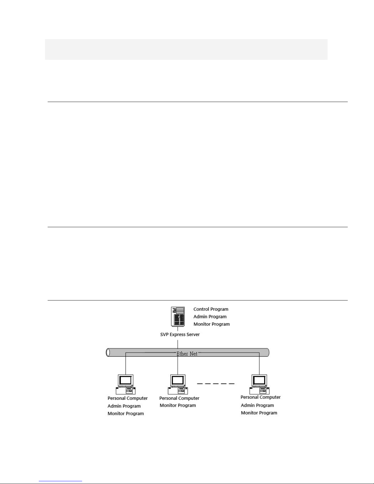
SVP Express is consisted of SERVER version and CLIENT version. SERVER version limits
one installation, license key are required whenever adding devices for central management.
SERVER version includes Admin, Monitor, Control and Web Monitor programs. The CLIENT
version is designed for monitoring purpose, and the Admin program is an option while installation
(for detail please refer to Section B. Running the Installation Wizard).
A.2.1. Client-Server System Structure
Page 8

Page 2
z System Requirement- SERVER version
CPU
P-4 3.0G
RAM
1G
Operating System
Windows XP Professional SP2
Network
10/100 Mbps Fast Ethernet
Display Card
1024 x 768 (XVGA) or above
z System Requirement- CLIENT version
CPU
P-4 1.2G
RAM
256 MB or above
Operating System
Windows XP Professional SP2
Network
10/100 Mbps Fast Ethernet
Display Card
1024 x 768 (XVGA) or above
z Networking Suggestion
SVP Express is optimized for small-scale project, simple LAN or simple WAN environment.
Place the system behind firewall or IP sharing device to efficiently protect this system from
hackers’ attack.
Page 9
Page 3
B. Running the Installation Wizard
B.1. SVP Express Server version – Installing
【Step 1】Please insert SVP Express CD into CD-ROM drive. Go to SVP
Express\Server directory to execute Setup.exe.
【Step 2】Select language
The Installation Wizard will select the language of your operation system intelligently.
SVP Express supports three languages:Traditional Chinese, Simplified Chinese,
English
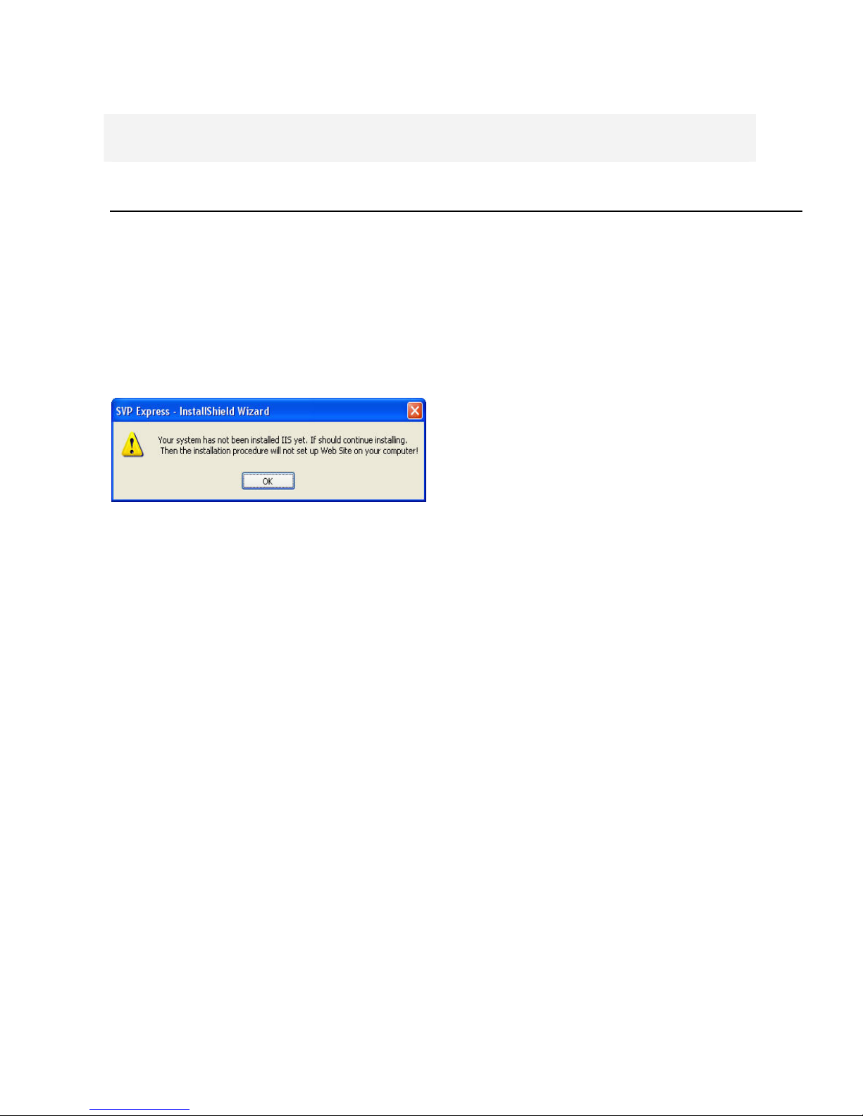
【Step 3】The Installshield Wizard will
check if IIS is installed at your system. If
not, you can continue installing SVP
Express, but you will not be able to use
the WEB monitoring feature without IIS.
To Install IIS, do the following,
1. Click “Start”.
2. Go to Control Panel Æ
Add/Remove Program
3. Click Add/Remove Windows
Component
4. Check Internet Information Services
(IIS)
5. Click “Next”.
6. Click “Finish”.
During the installation process, you may
need Microsoft Windows Operating
System CD.
Page 10
Page 4
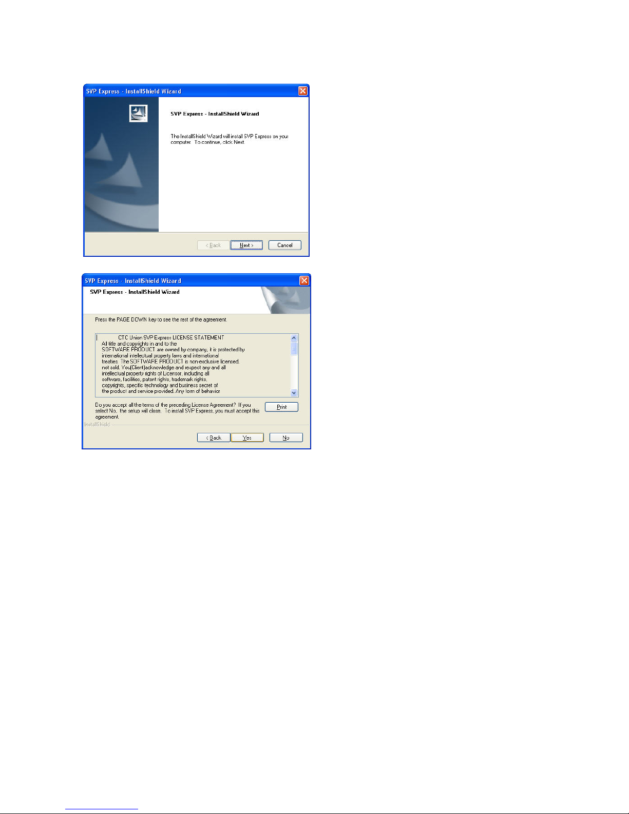
【Step 4】Click “Next” to begin the
installation process.
【Step 5】Please read the License
Statement and select “Yes” to accept
and continue.
Page 11
Page 5
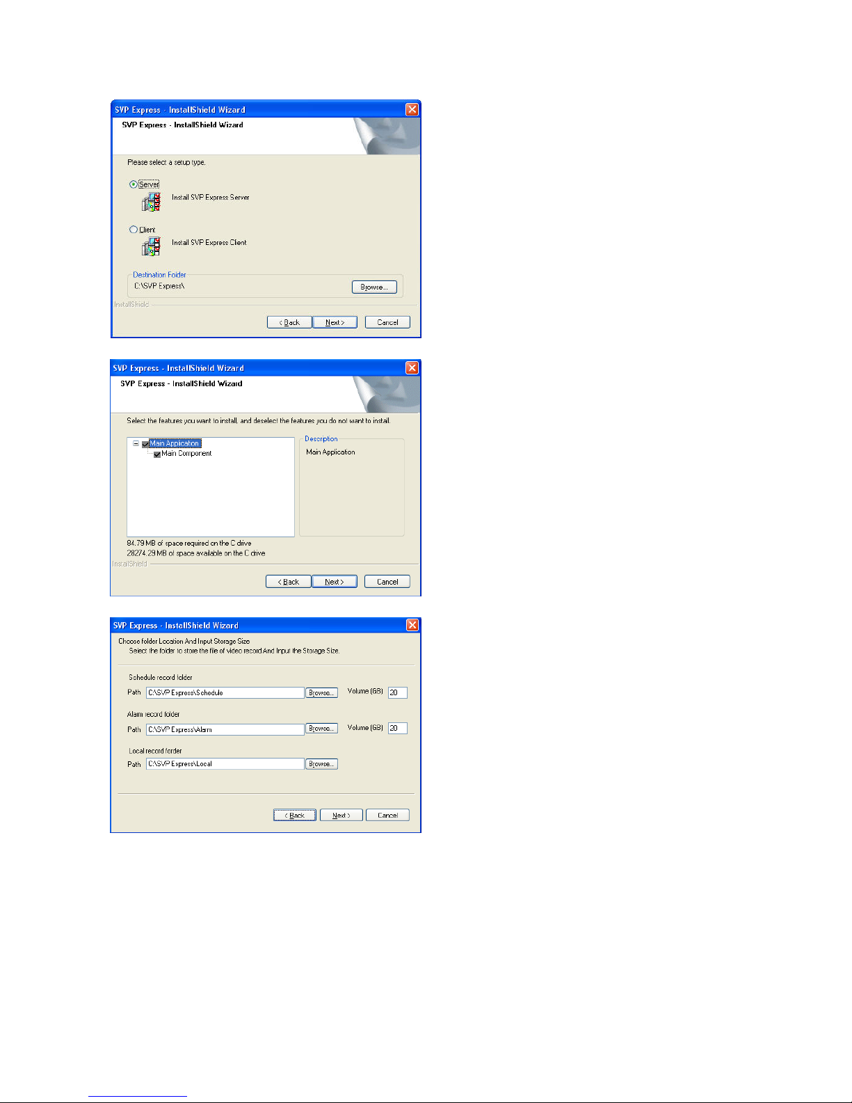
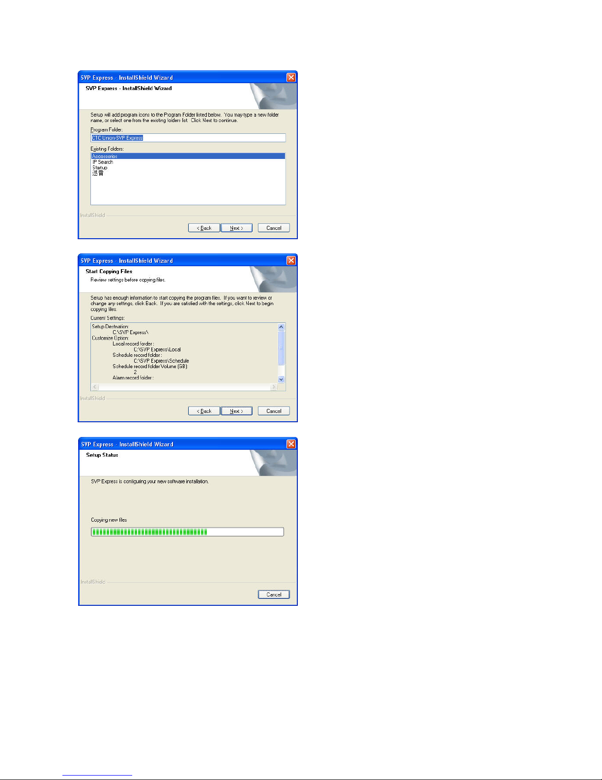
【Step 6】
【Step 7】
【Step 8】
Page 12
Page 6
【Step9】
【Step10】
【Step11】
Page 13
Page 7
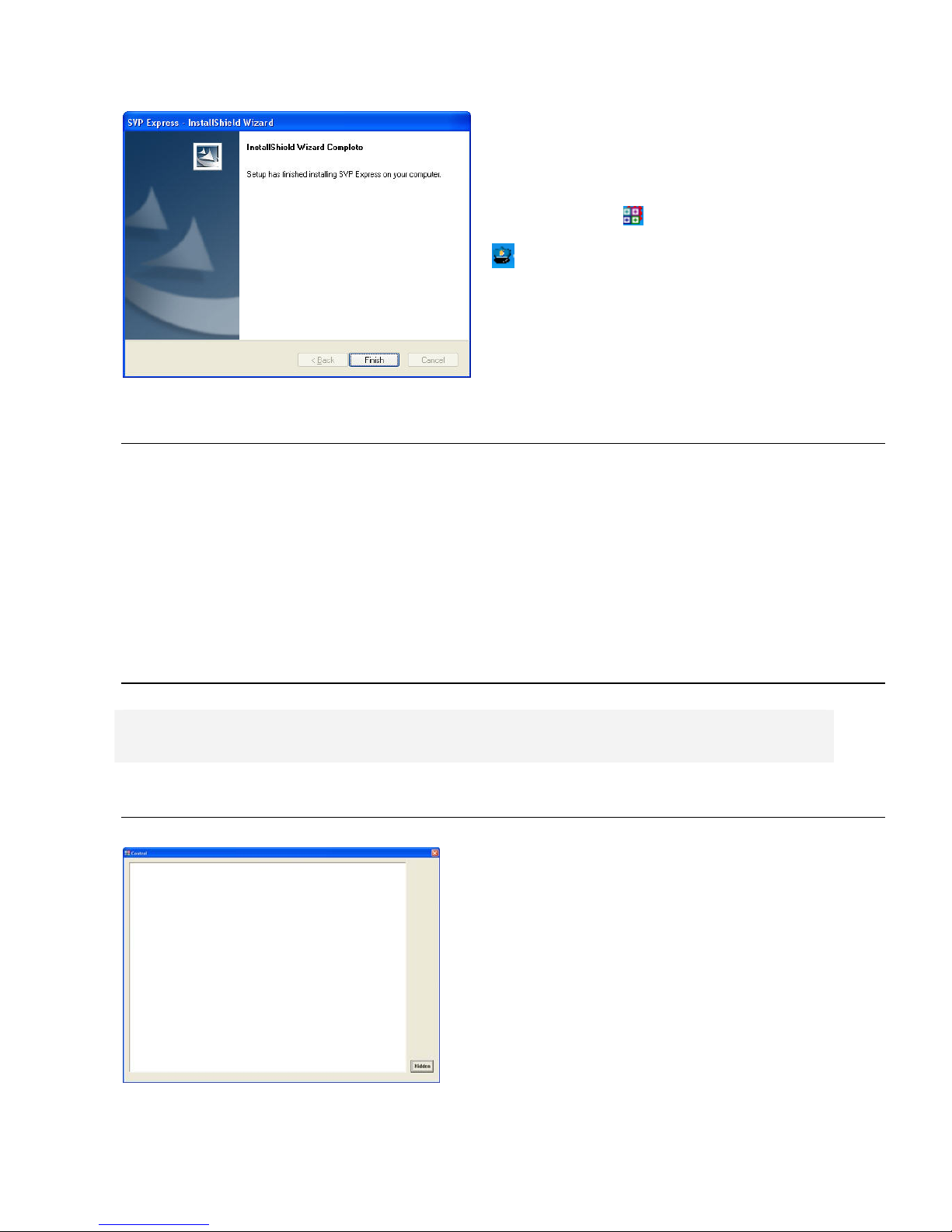
【Step 12】Installshield Wizard
Complete; click “Finish” to complete the
setup. The system should start SVP
Express in 1 to 3 minutes, and the icon
of UARGControl ( ) and WatchDog
( ) appear in task bar of screen’s
lower-right corner.
【Note】If in real case, this does not
happen, please restart your computer.
B.2. SVP Express Client version – Installing
Please insert SVP Express CD into CD-ROM drive. Go to SVP Express\Client directory to execute
Setup.exe.
【Note】
(1) You may freely install Client version to whichever computer you want.
(2) The rest steps are same as installing Server version.
B.3. Firewall Configuration
C. Control Program
C.1. Automatically starts upon system boot up
Only one instance of SVP Express Server’s
control program can be running at a time. The
computer with the running control program will
become a SVP Express Server. After
installation, the program can be found in the
windows start menu at Start Æ Programs Æ
SVP Express Æ Control. The Control program
will hide itself automatically after start up and be
displayed as an icon in the system tray.
Page 14
Page 8
C.2. Shutting Down the Control Program
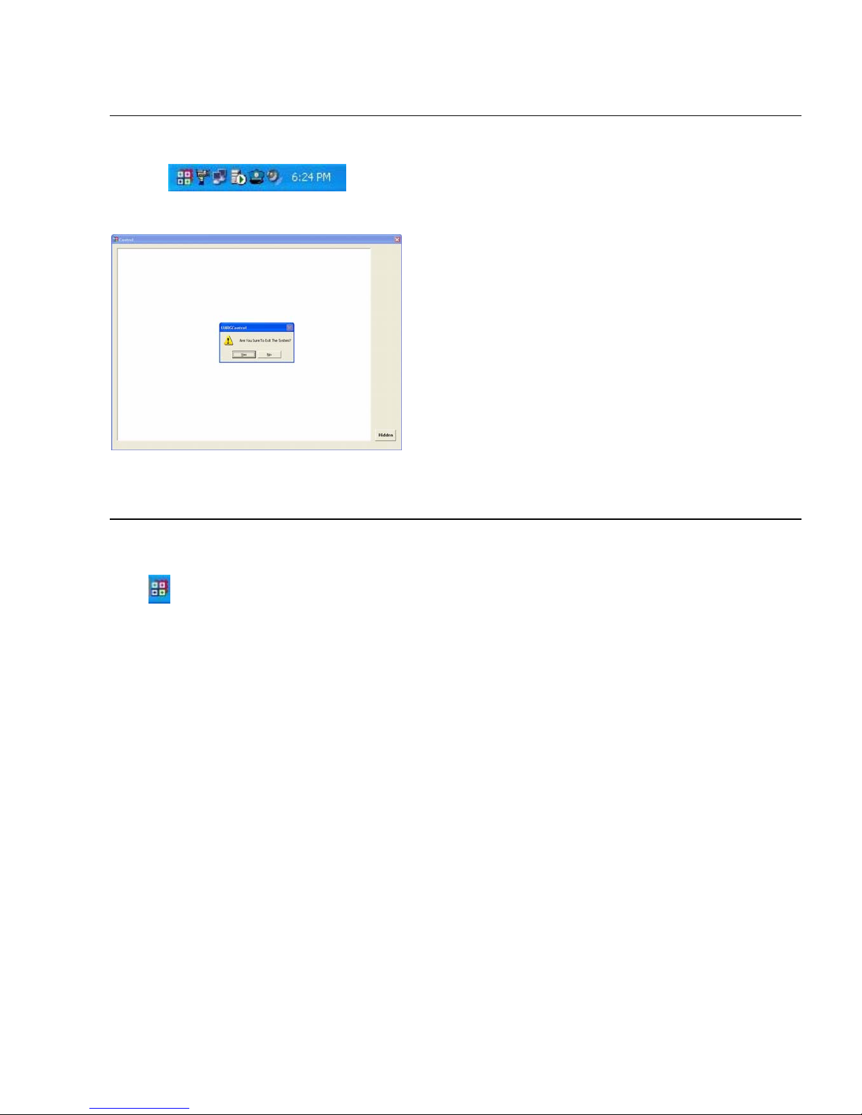
【Step 1】Find the Control Program icon in the
system tray, and double-click it. The Control
Program window will appear.
【Step 2】Click the [X] button in the upper right
corner.
You will be asked with a dialog “Are you sure
you to exit the system?”
Click “Yes” to exit the program.
C.3. Start the Control program manually
Navigate to Start Æ ProgramÆ SVP Express Æ Control. This will start the control program and its
icon will appear in the system tray.
Page 15
Page 9
D. Admin Program
D.1. Running the Admin Program
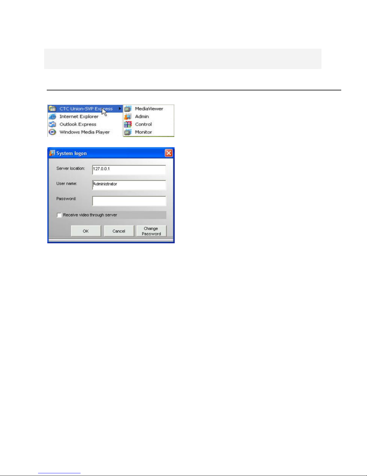
【Step1.】Select Start \All Programs \CTC
Union-SVP Express \Admin.exe
【Step2】 System Log on window.
z Server Location: “127.0.0.1” is the
default for local server. If you want to
access server from client, then please
enter the IP of server to this text box.
z User name: If this is the first time you
logon, use Administrator as default user
name and leave the password blank,
then click “OK” to log into the system.
z Receive video through server: If you
want to remote control SVP Express
server from client which is not within
intranet, then check this box.
【Note】 Password: The default password of
Administrator is blank. It is recommended
that you change password for security
management, please go to User Group
section to change the password.
Page 16
Page 10
D.2. Admin Interface Overview
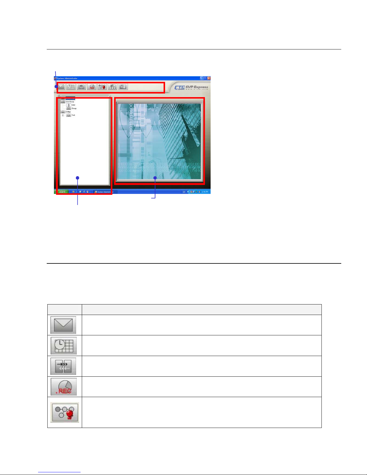
The System Admin screen is
divided into three areas:
z The Menu Bar area
z The System Setup area
z The eMap Interface area
If your system does not
display the screen properly,
please check if your display
resolution is at least 1024 x
768, and that the font size is
Windows system default.
SVP Express does not
support font sizes larger than
the Windows system default
one.
[Note] The buttons that appear in the Menu Bar depend on which administration function you are
using. For example, when you click the User Group icon in System Setup area, the Menu Bar
buttons will show related function accordingly. Details will be explained in the following sections.
D.3. System Management Overview
Select SystemAdm icon in System Setup Area, you will see the button in Menu Bar change
accordingly.
Button Use To
E-Mail Setting: Specify the email outgoing server for sending security alert.
Holiday Setting: Specify the calendar holidays for schedule setting which is
not included in weekly routine.
DNS Setting: Specify the Domain Name your computer registered for DNS
service.
Storage: Specify the path and storage for recorded file respectively.
System Alarm: Set alarm actions respond to the selected system alarm.
System Setup eMap Interface
Menu Bar
Page 17
Page 11
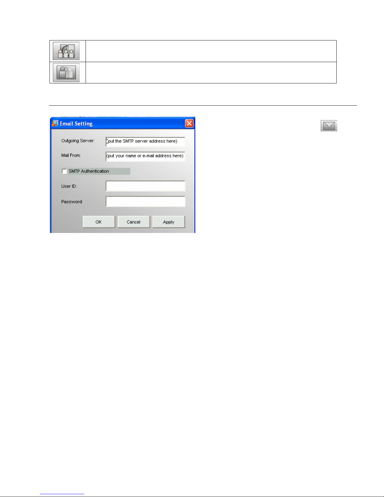
Rotation: Set the interval for image rotation in Monitor split screen.
Motion Rectangle: Set the square size of motion detection.
D.3.1. Email Setting
【Step1】By selecting E-Mail button( )
from the Menu Bar.
【Step2】You can specify the email server
that will be used when sending security alerts
via email.
【Step3】To authenticate on the mail server,
check SMPT Authentication and enter your
user name and password on the mail server.
z Outgoing Server: Enter the mail server which could forward your mail to receiver. Some
company mail server set the policy of exchanging email within company only. We suggest
you use the mail server of the receiver.
z Mail From: It is an email address display in the sending column.
Page 18
Page 12
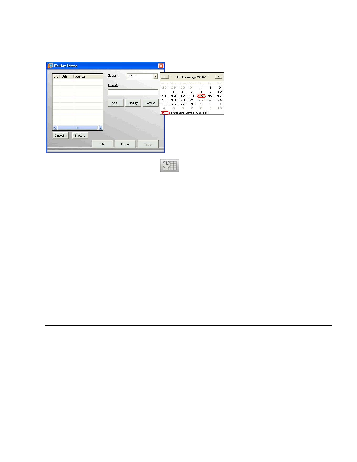
D.3.2. Holiday Setting
【Step1】By selecting Holiday button from Menu Bar. You may specify any
calendar holidays except weekend that may affect the security system settings.
【Note】User could enable alarm service full day during these holidays if you check
“Holiday” box in Section D.5.8.1.2. Network Camera Setting – Image Alarm.
z Export: If you have installed multi sites with SVP Express server they might
require the same holiday setting, you can set on one server first, and use the
“Export” function to save holiday setting.
z Import: You may update the holiday setting to another SVP Express server, by
copying the file to that server and use “Import” to update holiday setting
accordingly.
z Add: Input a description in the Remark field and click “Add” to add the date to the
list box at left.
z Modify: You can select a holiday from the list and use “Modify” to edit it
z Remove: Click “Remove” to remove it from the list.
D.3.3. DNS Setting
It is designed for the DNS resolution between SVP Express server and IP device. Your video IP
device will connect server via IP address of server if you did not enable DNS Resolution. But your
IP device will connect server via Domain Name which your server registered, so that alarm action
could be executed.
Page 19
Page 13
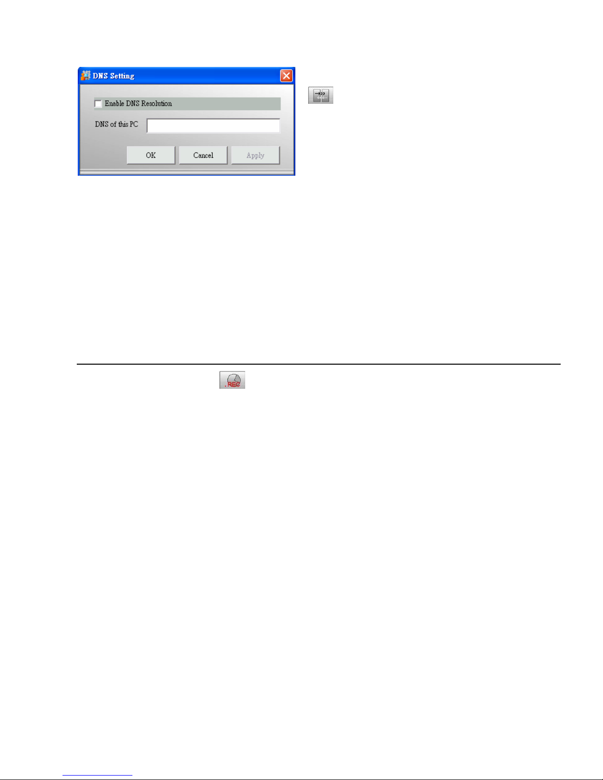
【Step1】By selecting DNS Setting button
from the Menu Bar, you may specify
the Domain Name Server.
【Step2】If your computer gets IP from
DHCP service or its IP changes periodically
due to the policy of your network
administrator, please check “Enable DNS
resolution”, so any alert message could be
delivered to SVP Express from camera no
matter what IP your server is assigned.
Enter the Domain Name your computer
registered to “DNS of this PC” field.
【Note】Please request a DNS for SVP
Express from your MIS.
D.3.4. Storage
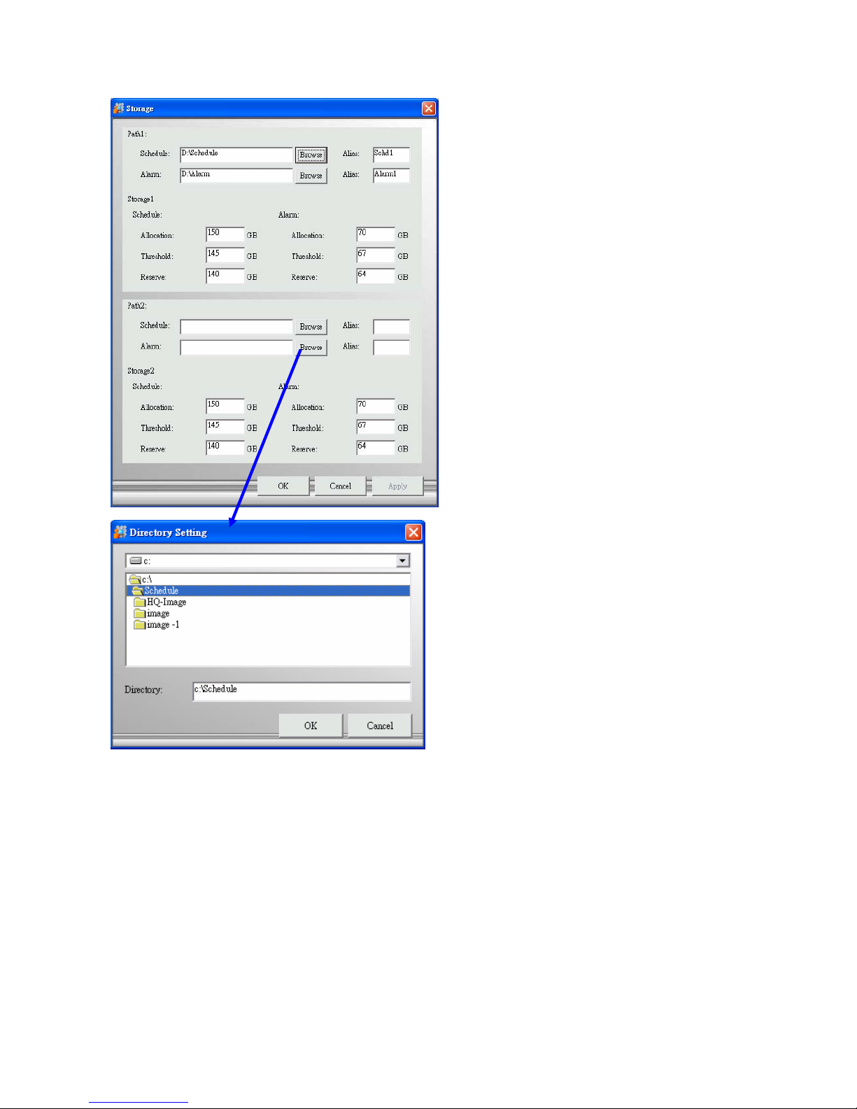
By selecting Storage button from the Menu Bar, you may configure the storage and
recycling rule. There is two different areas, namely area 1 (include path1 and storage1) and area 2
(include path2 and storage2):
Area 1: is assigned the disk to store recorded data.
Area 2: is assigned for the backup purpose, it is an optional service.
Page 20
Page 14
Path1 and Path2
Assigned the disk to store recorded
data of Schedule and Alarm.
(Alias: suggest to give an alias for the
path, so that path could be easily
differentiated)
Storage1 and Storage2
Set the maximum disk space for
recording image.
Allocation: The storage allocation
should be no less than 2 GB.
Threshold: When the image data
exceeds 90% of allocation, SVP
Express will trigger a warning
message to related parties. Threshold
no less than 1.8 GB.
Reservation: SVP Express will
overwrite historical data when it
reaches 80% of allocation.
Reservation no less than 1.6 GB.
Browse: You may change the default
path.
z Directory: please do not choice
the directory which has install the
operation system. (Generally C:\
is designated to windows
operation system is installation)
z Folder: double click the folder
which you want to save recorded
file, the folder name will display in
the “Directory” field, click “OK” to
save the setting and folder name
will be created by system.
【Note】
Recording video over a long period of time will consume large amounts of disk space.
Make sure that you have at least 2GB disk space available if you want to use recording
function.
Path 2 is assigned for the backup purpose, it is an optional service. If this is configured,
identical recording information will be written to both path 1 and path 2.
Page 21
Page 15
D.3.5. System Alarm
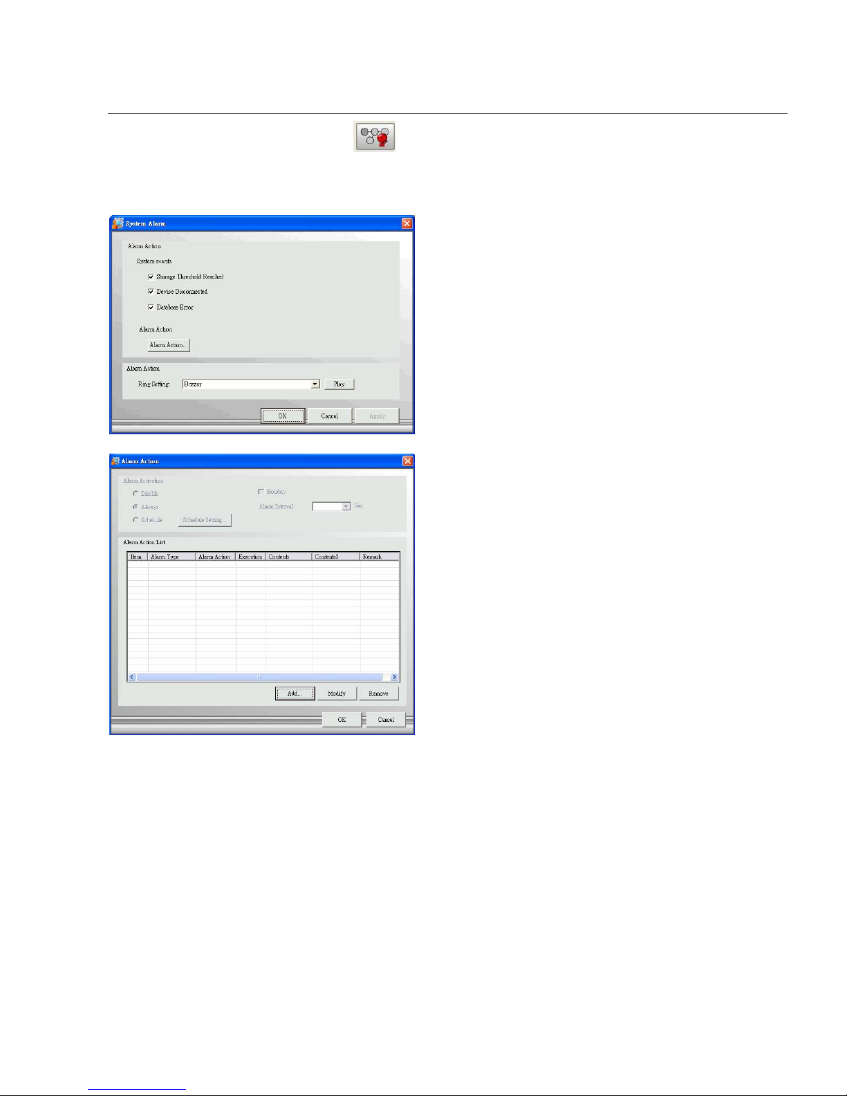
By selecting System Alarm button from the Menu Bar, you can turn on system diagnosis
and alarm action.
Alarm Action from three system
events:
1. Free space is running short.
2. Device Disconnects.
3. Failed to save recording data
Alarm Ring Setting: there are 4
sounds effect to be selected.
Any system event will trigger alarm
action, please refers to Section
D.5.8.1.2. Network Camera Setting –
Alarm Action for detail.
Page 22
Page 16
D.3.6. Rotation
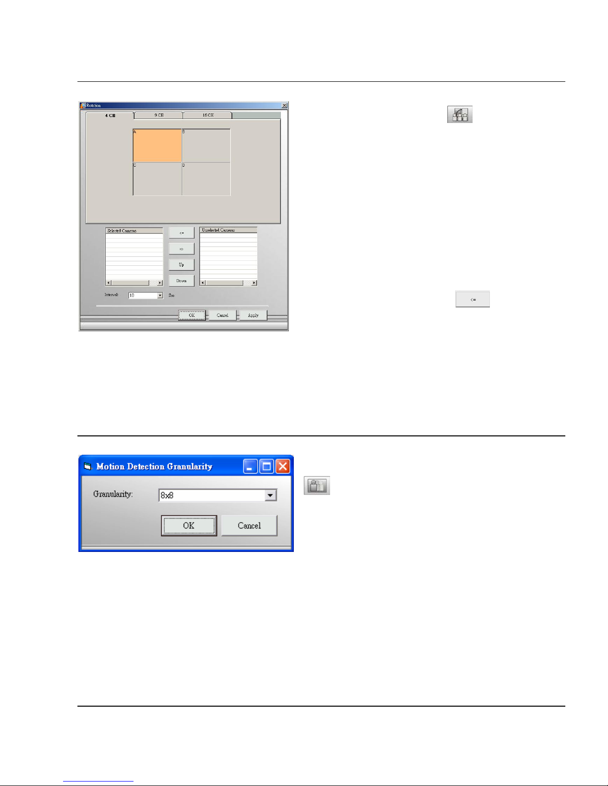
By selecting Rotation button from the
Menu Bar, you can set the camera to
assigned split screen and rotation interval.
【Step 1】Select the Tab of split screen,
4CH, 9CH and 16CH.
【Step 2】 Assign camera to split screen:
Take 16-splitscreen as example: select Tab of
16CH, and select the split-ed screen (remark
the selection by changing color to orange) to
move camera from “Unselected Column” to
“Selected Column” by clicking
button.
【Step 3】Set Rotation Sequence.
You can adjust camera sequence by clicking
up/down button and also set the rotation
frequency by selected interval.
D.3.7. Motion Rectangle
By selecting Motion Rectangle button
from the Menu Bar, you can set the
square size of detected area.
Page 23
Page 17
D.4. User Group
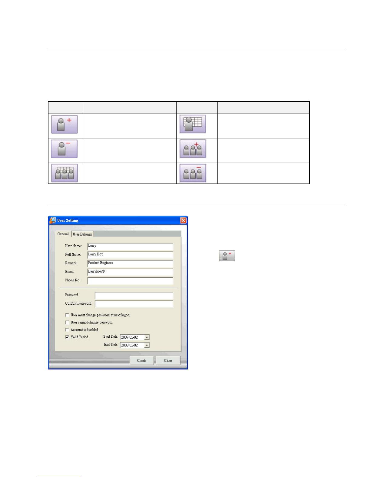
The User Group functions in System Setup area is for managing user privileges. Default user
“Administrator” is created with full privileges during installation. You may add users to the system
and differentiate their privilege by designating them to different groups.
Button Use To Button Use To
Add User
User Setting
Remove User
Add Group
Group Setting
Remove Group
D.4.1. User
Add User
【Step 1】Select User icon in the System
Setup area, then click the New User
button in the Menu Bar.
【Step2】Enter user information in the
“General” Tab.
【Note】For security concern, it is
recommended to assign Password and
tick the box for password changing and
validation.
Page 24
Page 18
User Belongs
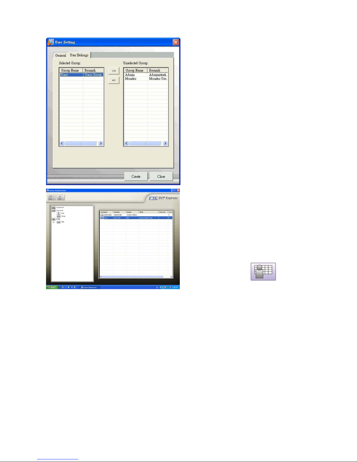
【Step3】Designating a User to a Group
Select the “User Belongs” tab to
designate a user to a group.
Select the group name and move it
between “Selected group” and
“Unselected group”. Click “OK” to
continue.
After setting both general information and
user belongs, click “Create” to save the
setting.
User Setting (Modify)
【Step1】Select User Setting
Select User icon in the right, the User
Table display in the E-Map Interface area,
when select any user icon from the User
Table, the User Setting Button will display
in the Menu Bar accordingly. Then click
the Edit User button
in the
Menu Bar.
【Step2】Modifying user Information
You may change the information by
modifying the general information or user
belongs of that user.
Page 25

Page 19
D.4.2. Group
z Admin Group is the user group that has the
full privilege to the Admin and Monitor
programs. The user of “Administrator”,
system default and belong to “Admin
Group”, can add users and assign users to
whatever user group.
z Monitor Group is the group for general
users that has the full privilege to the
Monitor program.
z User Group is the group for viewing
monitor program only.
Add Group
【Step1】 Select the User icon in the System
Setup area, then click Add User Group button
in the Menu Bar to add the user
group’ s data.
【Step2】 Give a name to the new group and
group the selected users here in one step.
Page 26
Page 20
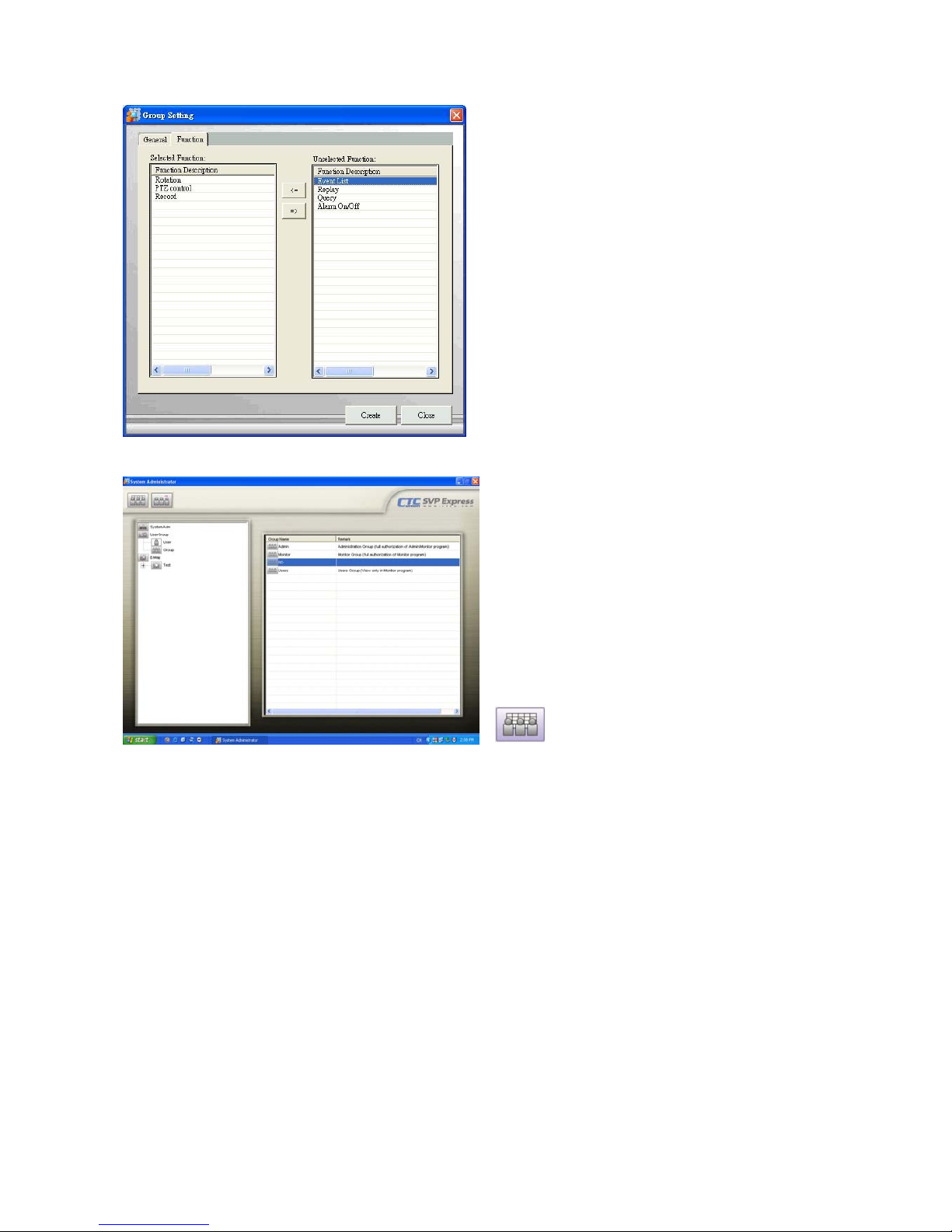
【Step3】 Select the “Function” tab to
designate function to a group.
Select the function list and move them from
“Unselected function” to “Selected function”.
Click “OK” to continue.
【Step4】 After setting both T ab of “General”
and “Function”, click “Create” to save the
setting.
Modify Group
【Step1】Select User Group
Select User Group icon in the System Setup
area, the User Group Table display in the
right area, when select the icon from the
User Group Table, the User Group Setting
Button will display in the Menu Bar
accordingly. Then click the Edit User button
in the Menu Bar.
【Step2】Modify User group Information.
You may change the information by
modifying the general information or function
of that user group.
Page 27
Page 21
D.5. Area and eMap management
Area refers to the geography and device scope of SVP Express. Area is a prerequisite of any
device setting (device includes: video server, Network Camera, camera image, relay or sensor),
SVP Express provides multi-areas to meet user different requirement.
eMap refers to (1) a hierarchical tree-structured management tool in System Setup area (2)
background of the area, it could be a picture or a map (3) an interface which combines eMap
background and device icon, eMap visually presents the devices in your security system.
To configure a new system, select eMap icon in the System Setup to bring up the Area button in
the Menu Bar. Select the newly created area under the eMap branch and use the corresponding
menu options to add a Network Camera or Video Server to your system or to upload a background
picture to the eMap Interface.
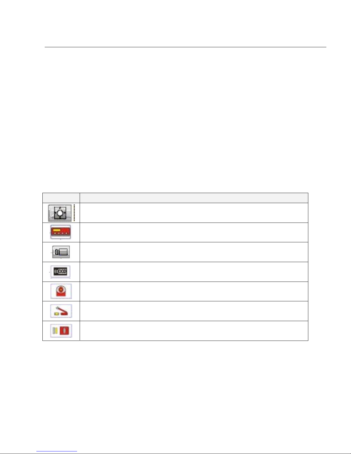
Icon Overview
Icon Representing
Area icon: The first level of the eMap hierarchy, the place to add a device.
Video Server:Depending on the device model. There may be an image, a
sensor, or a relay under this object.
Network Camera:Depending on the device model. There may be an image, a
sensor, or a relay under this object
Image icon: The image component of a camera.
PTZ icon: The image component of a PTZ Dome camera.
Relay icon: The image component of a Relay setting.
Sensor icon: The image component of a Sensor setting.
Page 28
Page 22
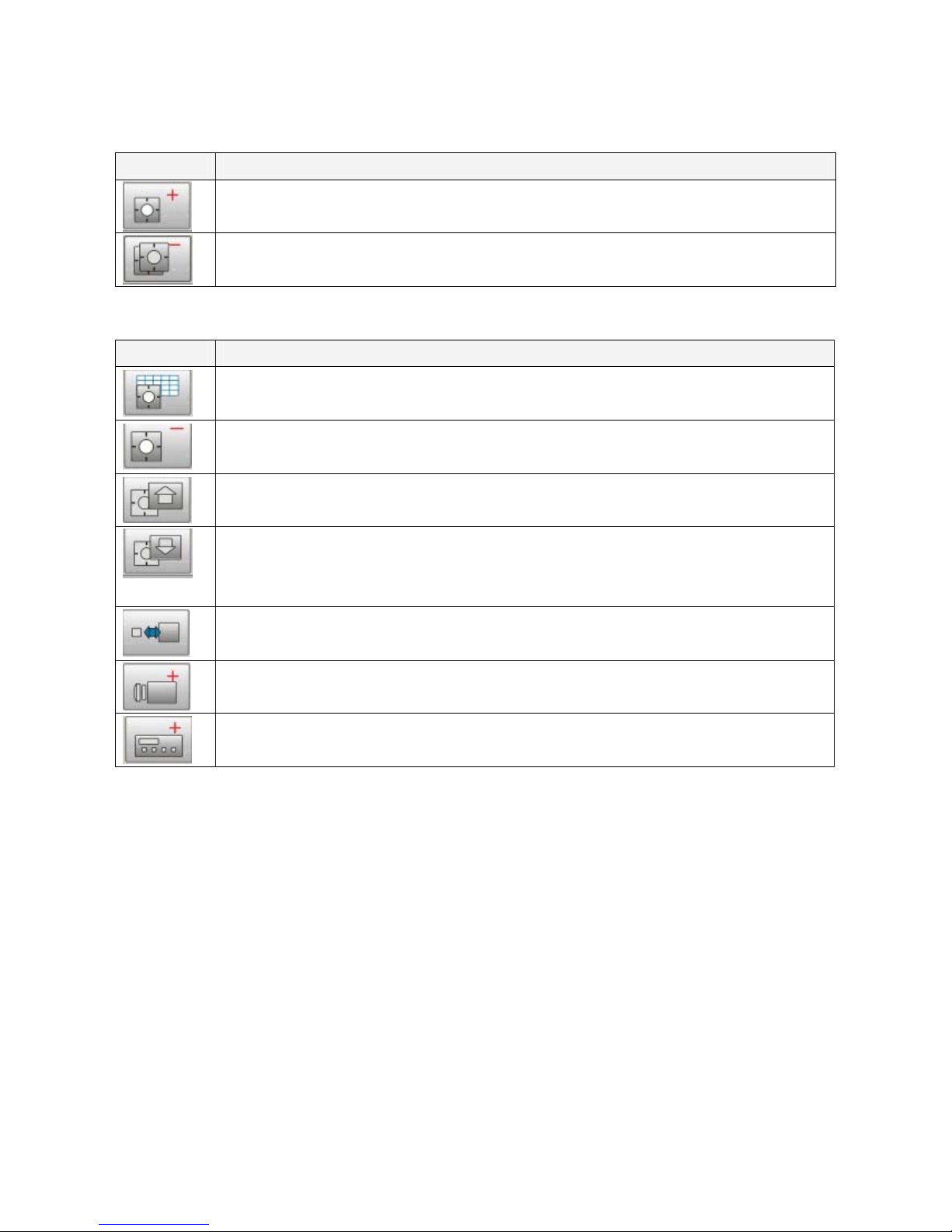
Button Overview
When you select eMap icon, Menu Bar will display the following functions:
Button Use to
Add Area: This button allows you to add a new area under eMap branch.
Remove Subarea: This button allows you to remove all areas and devices
that are under the eMap branch.
When you select the Area icon, Menu Bar will display the following functions:
Button Use to
Rename the Area: This button allows you to edit a name of a selected area.
Remove Area: This button allows you to remove a selected area and all
devices in that area.
Upload eMap: This button allows you to upload a blueprint or map to a
selected area.
Refresh eMap: This button allows you to refresh a blueprint or map from your
PC to get updated in case a new eMap was uploaded from server or another
client access.
Resize eMap icon: This button allows you to change the ratio of the device
icons to display on the eMap interface.
Add Network Camera: This button allows you to add a new IP Cam, Speed
Dome and Fix Dome to the area.
Add Video Server: This button allows you to add a new video server to the
area.
Page 29
Page 23
D.5.1. Add Area
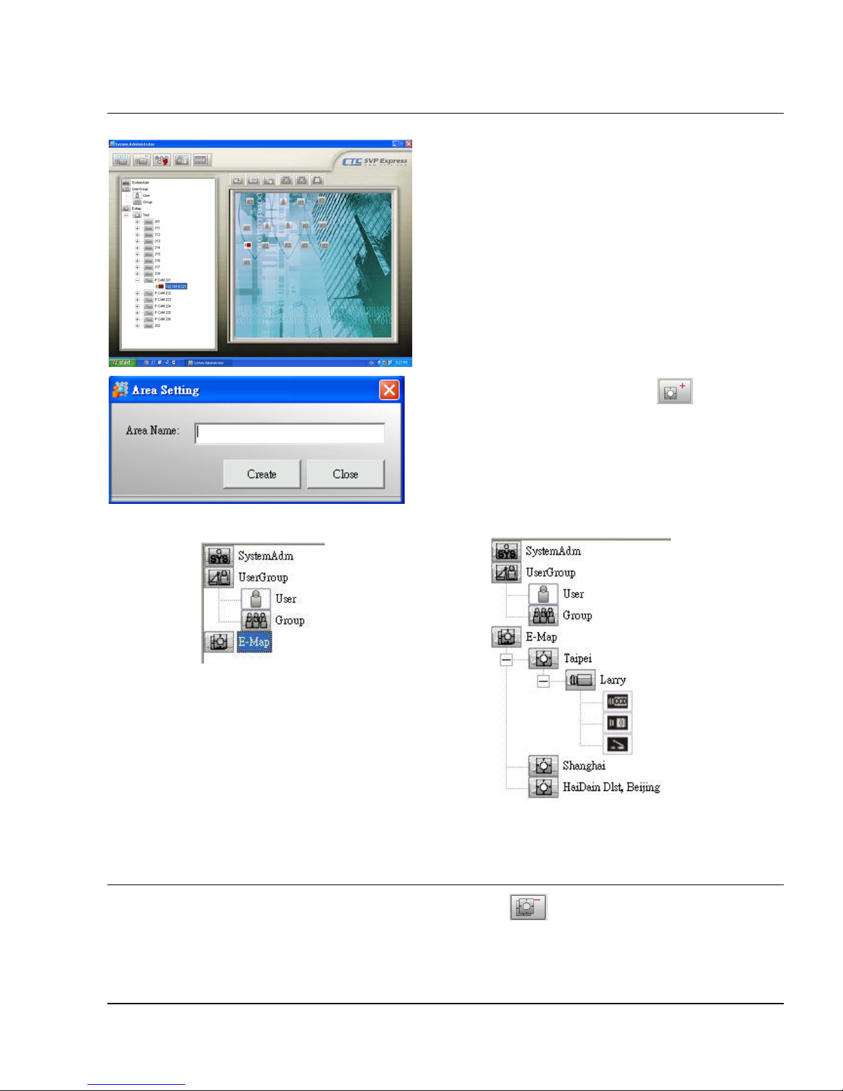
【Step1】Select eMap icon from the System
Setup.
【Step2】Click Add Area button from
the Menu Bar. An Area Setting window will
pop up. Enter the name to the “Area Name”
textbox.
【Step3】Click “Create” to save setting, a newly created area demonstrate as following:
Before Add Area
After Add Area
D.5.2. Remove SubArea
Select eMap icon, then click the Remove All Areas button . A warning message pops up
confirming if you want to remove all areas and devices under area. Click “OK” to confirm.
D.5.3. Rename the Area
Page 30
Page 24
Select Area icon, then click the Rename Area button . You can modify this area name.
D.5.4. Remove Area
Select Area icon, then click the Remove Area button . A warning message pops up to get
your confirmation. Click “OK” to confirm.
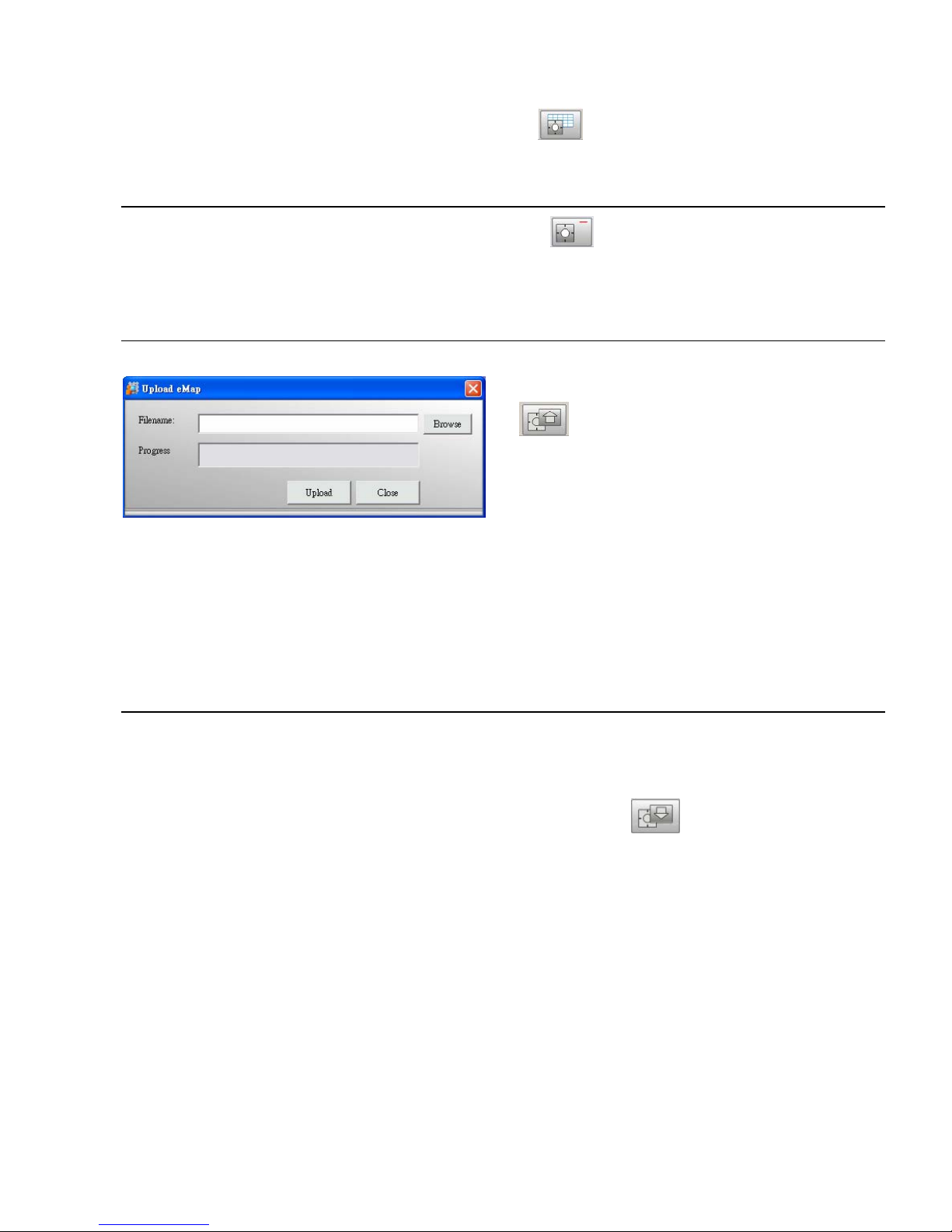
D.5.5. Upload eMap
【Step1】Select Upload eMap button
in the Menu Bar. An Upload eMap
window will pop up.
【Step2】Click “Browse” to navigate the
image file representing the area that you
wish to secure, and then click “Upload”
button.
【Note】Image files can be in the format of *.jpg, *.gif, *.bmp, *.wmf, *.emf, *.ico.
D.5.6. Refresh eMap
For the system performance, all the admin setting are kept by cache, so if the server eMap is
changed from the client PC, then the others PC, no matter server nor client is, need to refresh the
eMap background manually by clicking the Refresh eMap button
.
Page 31
Page 25
D.5.7. Resize eMap Icon
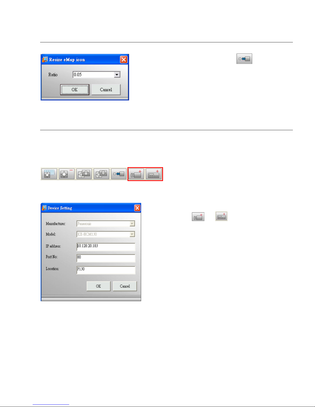
【Step1】 Select Device Ratio button in
the Menu Bar. A Resize eMap icon window pops
up.
【Step2】Select the ratio of device and click “OK”,
the icon display in eMap interface will change it’s
ratio accordingly.
D.5.8. Device Management (Network Camera, Video Server Controller)
New device should be added and configured in SVP Express Admin program. The following
section will explain the details of network camera and video server. The supported H/W
manufactures and models for each device can be found in the SVP Express Hardware Support list.
Adding Device (Network Camera / Video Server controller)
Add Device
【Step1】Click or button from
the Menu Bar to bring up the Device Setting
window. Type information to textbox as
following:
Manufacturer: Device manufacturer.
Model: Device model.
IP address: IP address from your chosen
device you wish to connect to.
Port No: The default port number is 80,
which can be edited to match with camera
web configuration.
Location: The naming of newly added
device.
Page 32
Page 26
【Step2】After device is added, please
process the Image Setting (refer to Section
D.5.8.1.2. Network Camera Setting – Image
Setting).
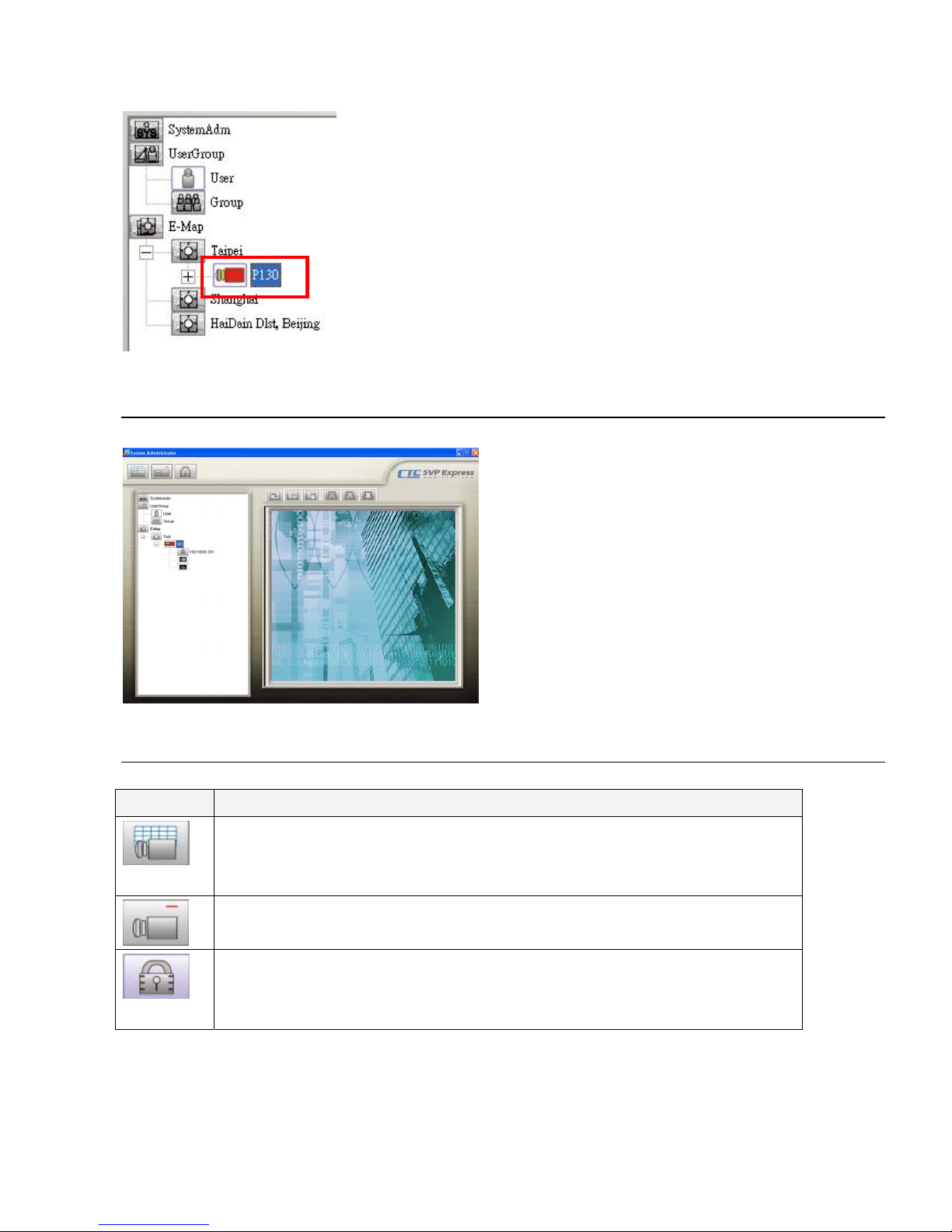
【Note】In the left example, the Network
Camera now appears under Area icon - the
device tree of System Setup area, and of
cameras (images) icon appear under the
camera tree.
D.5.8.1. Network Camera
Select Network Camera icon
When select Network Camera icon in
System Setup area, the buttons display in
Menu Bar as left bar.
D.5.8.1.1. Network Camera Button Overview
Button Use To
Network Camera Setting: to configure IP/ Port Number associated to a
selected device, it displays the information set in Add Network Camera
button for further modify
Remove Network Camera: to remove the configuration of a selected
Network Camera including the image under it.
HW Password: to change the User Name or Password of selected
Network Camera from SVP Express or to sync with the direct change in
device.
Page 33
Page 27
D.5.8.1.2. Network Camera Setting Overview
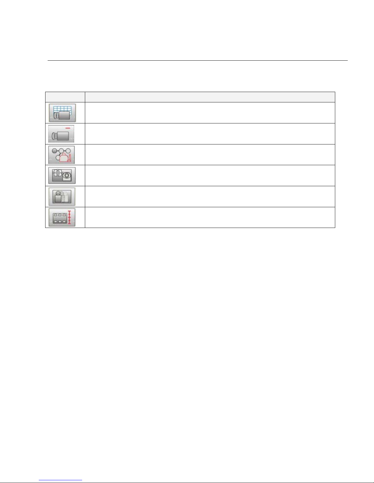
When select Camera Image icon in System Setup area, the buttons display in Menu Bar as
following:
Button Use To
Image Setting: to configure frame per second of recording and activate
schedule recording for that camera image.
Remove Image: to remove all the configuration of a selected camera image.
Image Alarm: to set alarm action when alarm is detected on selected camera
image.
Preset Setting: to set preset point under preset setting.
Motion Detection: to specify area for detecting motion.
Image Quality: to configure the contrast, hue, brightness and resolution of
camera image.
Image Setting
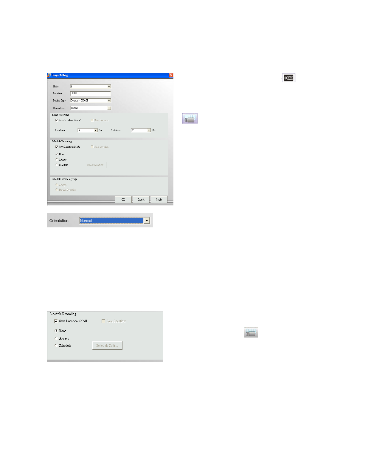
All the setting item defined as following:
z Nodes: the number of camera nodes of Network Camera and video server could be varied
base on what models is selected.
z Location: to differentiate the device image source. Please give a meaningful description that
identifies the installed location.
z Device Type: here are two options of device type which are the Speed Dome or General-CCD.
Speed Dome should only support the models which are on the list, but General-CCD has no
model limitation. You can freely connect to whatever General-CCD as you like. (Currently we
support General-CCD only.)
z Orientation: Normal or Inverted to get image up-side down.
z Alarm Recording: you may define the “frame per second” and the seconds of “pre-alarm”
and “post-alarm” of alarm recording.
z Save Location Alarm1: here display the alias of recorded path. For detail, please refer to
Section D.3.5. Storage.
z Schedule Recording: you may define the “frame per second” (only for MJPEG camera) and
recording schedule.
z Save Location Schd1: here display the alias of recorded path. For detail, please refer to
Section D.3.5. Storage.
Page 34
Page 28
z Recording Type: Schedule recording could be activated by clicking to select “Always” or
“Schedule”, and check Recording Type of “Motion Detection” to significantly reduce the
storage of schedule recording.
【Step1】Select the Image icon of
a Network Camera in the System Setup
area, and click Image Setting button
from the Menu Bar to bring up the
Image setting window.
【Step2】Click “Create” to save the
setting.
Set Orientation
Click on the right of Image Rotation drop
list to support different camera mounting
methods. Here are “Normal” and
“Inverted” for your option.
【Note】
(1) Monitor program requires restarting
to activate the new setting.
(2) This configuration requires 20 sec at
least to reconnect camera.
Schedule Recording
【Step1】Select the Image icon and click
Image Setting button to bring up the
Image setting window.
【Step2】Select “Recording Type”
Check the Schedule in Recording Type
first, and you will find that the Schedule
Setting button is enabled.
Page 35
Page 29
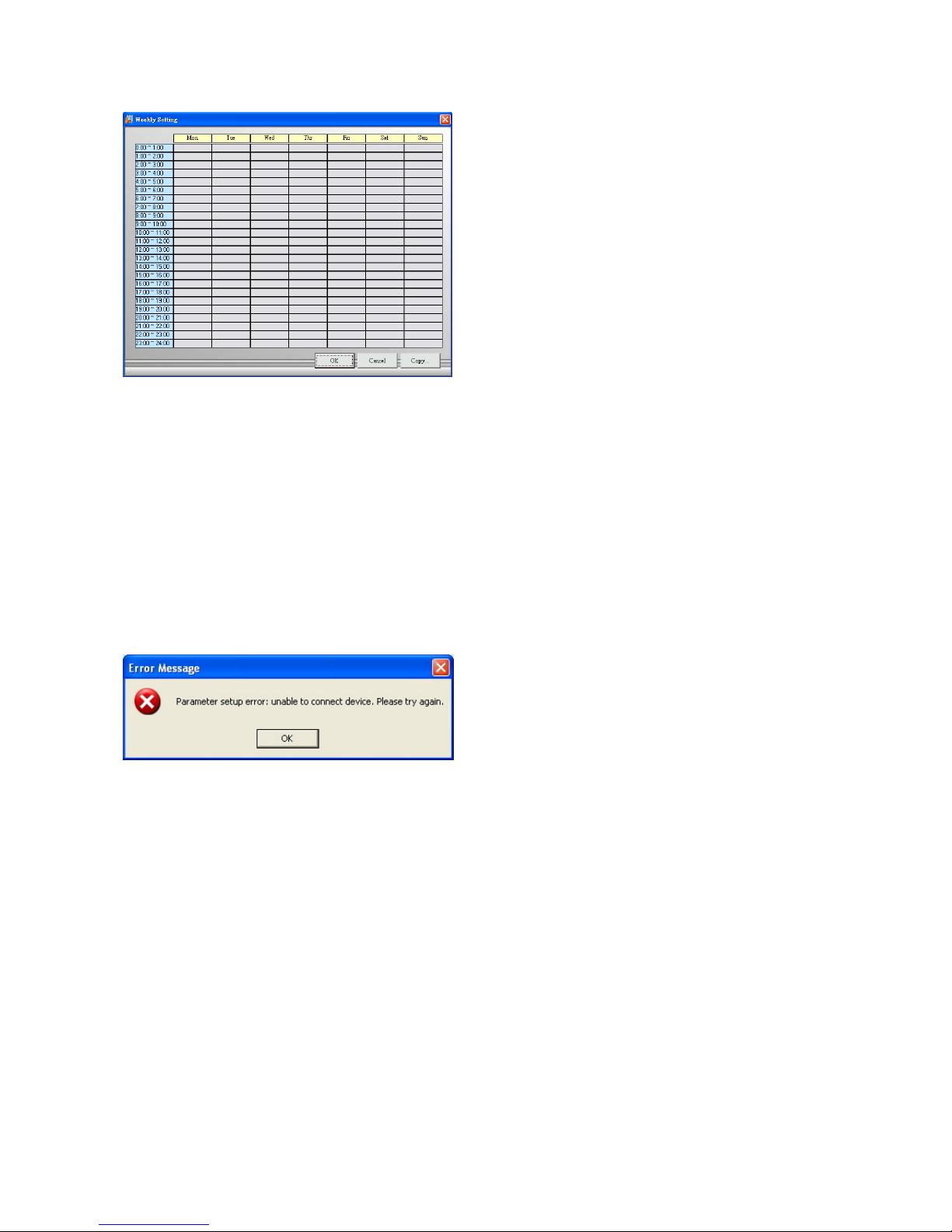
【Step3】Schedule a Weekly Setting
Click the Schedule Setting button. A
Weekly Setting table will pop up. Select
the time period for which you want to
schedule a recording. The activated
block will turn pink.
【Step4】Edit a Schedule
To cancel or modify a schedule setting,
click the pink block to deactivate it.
【Step5】Run schedule recording
automatically
Schedule recording will be executed
immediately after click “OK” in Weekly
Setting and Image setting window.
Copy..: If you want to copy the setting
from one of the existing setting, click
“Copy” to select the device you want to
copy from, you can easily copy all the
setting information. This function could
be found in Image setting, weekly setting,
alarm action, etc.
【Note】Weekly setting is a cycling setting which is automatically applied to the
following week, with each block being equal to 1 hour.
If an error message pops up, please
check if any related device is unable to
connect due to the information described
in Error Message window. Solve the
problem, and then go back to Network
Camera Setting button to configure this
device again.
Remove Image
Remove all the configuration of a selected camera image.
Page 36
Page 30
Image Alarm
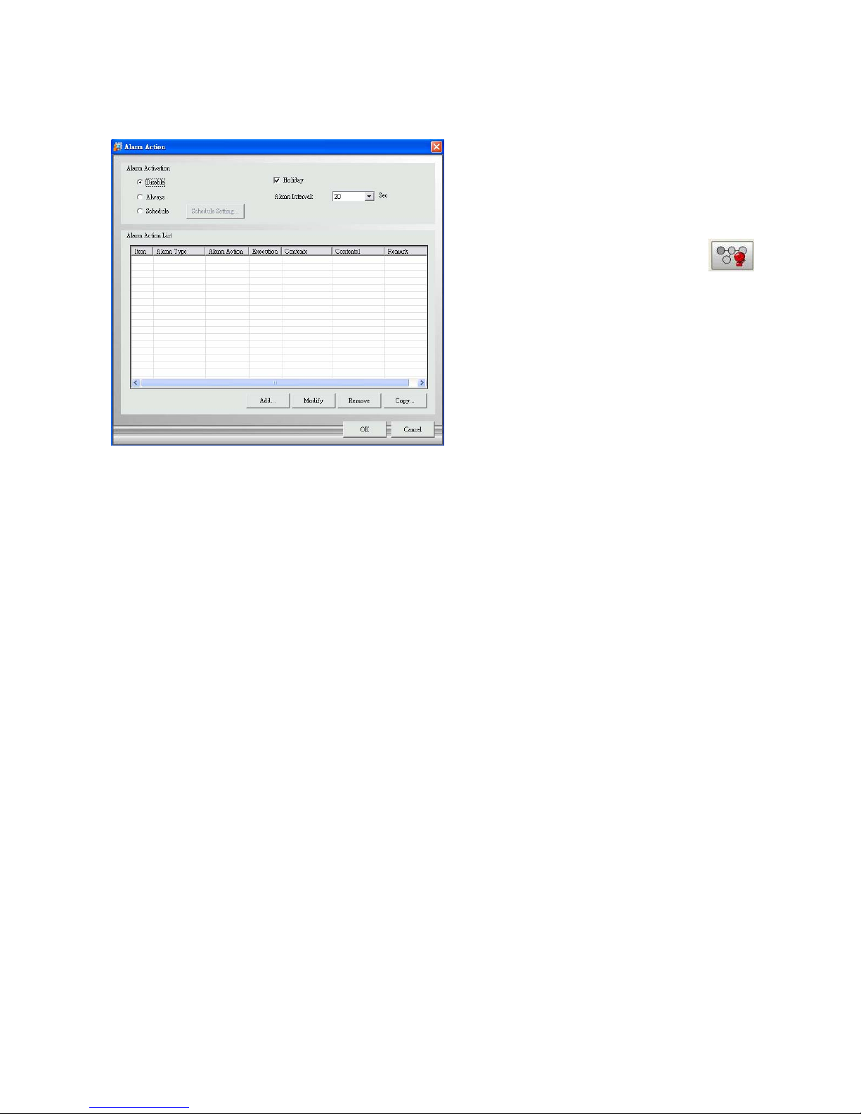
Activate Alarm Action
【Step1】St art Alarm Action
Select the Image icon of a Network
Camera/Video Server in the System Setup
area, and click Alarm Action button
from the Menu Bar to bring up the Alarm
Action window.
【Step2】Select the Alarm Activation Type
It is disabled by default you can change to
“Always” to turn it on, or “Schedule” to
activate it per schedule defined in Schedule
Setting.
【Step3】The “Holiday” Option
“Holiday” check box only works with Schedule, you may click to check “Holiday” to activate
alarm action full day during holiday, regardless the scheduled time in previous setting. The
holiday is also user-definable. (Please refer to Section D.3.2. Holiday Setting)
【Step4】The “Alarm Interval”
Configure the number of seconds between alarms. If successive alarm occurred during this
interval, it will be ignored. The total seconds of pre-alarm and post-alarm are suggested to be
the minimum of alarm interval.
【Step5】Click “Add”… to add new Alarm Action.(Detail please refers to Section D.5.8.1.2.
Network Camera Setting – Image Alarm)
【Step6】Click “OK” to save all alarm action configuration (including “Add”, “Modify”, “Remove”
and “Copy”) and dismiss this window. Click “Cancel” to ignore all configurations and dismiss
this window.
Page 37
Page 31
Alarm Action
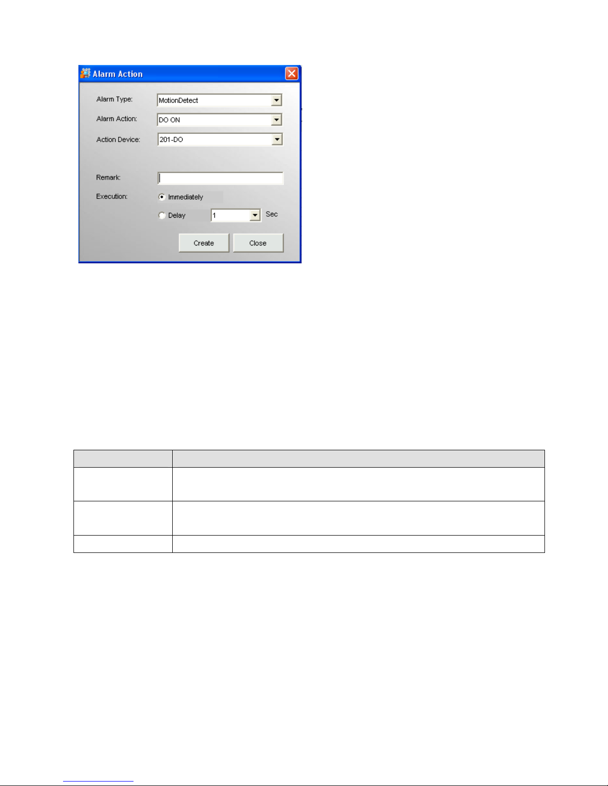
【Step1】To add Alarm Action by clicking
“Add” to continue.
【Step2】“Alarm Type” go with the icon you
selected.
If select camera image icon, then it bring up
Motion Detection as alarm type.
【Step3】Select Alarm Action (refer to Alarm
Action Table)
【Step4】Select “Action Device”, and enter
the information to “Remark” field.
【Step 5】Set “Execution” time。
Action execution could be set by the delayed
second you configured here. This setting
does not apply to Live Video, which is always
executed immediately.
【Step6】Create it to Alarm Action List
Click “Create” to add action to alarm action
list. If no further action to add, click “Close” to
dismiss this window.
Alarm Action Table
Alarm Action Use To
Email The email and take snapshot of breached device, one Email receiver at
an action.
Live Video The live video of breached camera, it will pop up in Monitor’s 4-split
screen.
Recording The alarm recording of breached camera; it is set by number of seconds.
“Alarm Breach” Scenario
Set alarm triggered by Camera-image 1 and records the video of Camera-image 2:
Select Camera-image 1 icon in System setup Area and click Image Alarm button from Menu
bar, then select “Alarm action” by Recording and “Acting Device” by “Camera-image 2”.
“Alarm Live Video” Scenario
1. If only one alarm is triggered, the different device breached by “live video” alarm action will
Page 38
Page 32
be displayed on the 4 split screen of Monitor Program and is arranged starting from
upper-left to upper-right, lower-left, and lower-right.
2. If live video is breached by different alarm source, live video is display respectively. The
live video of latest event will replace the live video of old event. If the number of live video
is greater than 4, they will be displayed rotationally.
3. Dismiss the live video in 4-split of monitor program: click “Cancel Alarm” button in Monitor
Program.
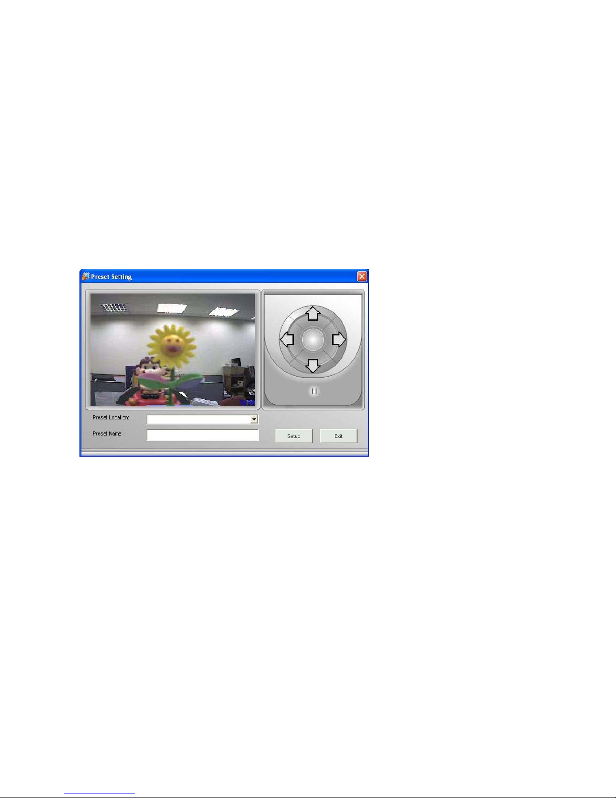
Preset Setting
Click the Preset button to bring the preset setting dialog, as shown below:
【Step1】Select a Preset Location
from the dropdown list and give it a
meaningful name in Preset Name.
【Step2】Press “||” to pause the video
location.
【Step3】Adjust the gimbal direction
using the narrow buttons.
【Step4】Click Setup to store this
location into the gimbal, if it supports
preset location.
[Note] This will also overwrite the
previous setting stored in this preset
location. Preset locations can not be
removed.
Set the other preset locations in the
same process. Click “Exit” to leave
this dialog.
Page 39
Page 33
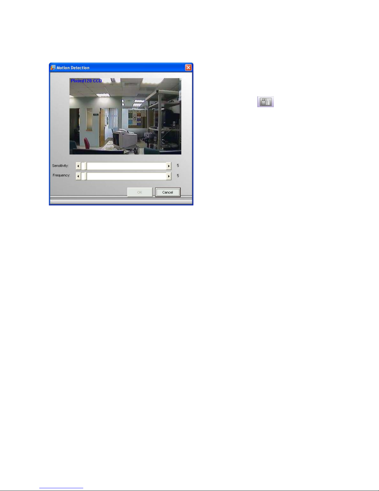
Motion Detection
【Step1】Select the Image icon of a
Network Camera/Video Server in the
System Setup area, and click Motion
Detection button from the Menu
Bar to bring up the Motion Detection
window.
【Step2】Set Detection Area: A red
square follows mouse movement, click
to place the red square to the area of
motion detection or click to deselect a
specified area. Any motion within the
detected area should over the threshold
of sensitivity to trigger a motion detection
alarm.
【Step3】Sensitivity and Frequency
setting.
Sensitivity refers to the pixels of image
changes, and Frequency refers to the No
of frame mapping.
【Note】The size of red frame is configurable in Motion Detection Granularity , det ails please
refer to Section D.3.7. Motion Rectangle.
Different camera may have different interface for motion detection adjustment. Some may
require you to install Active-X components.
Page 40
Page 34
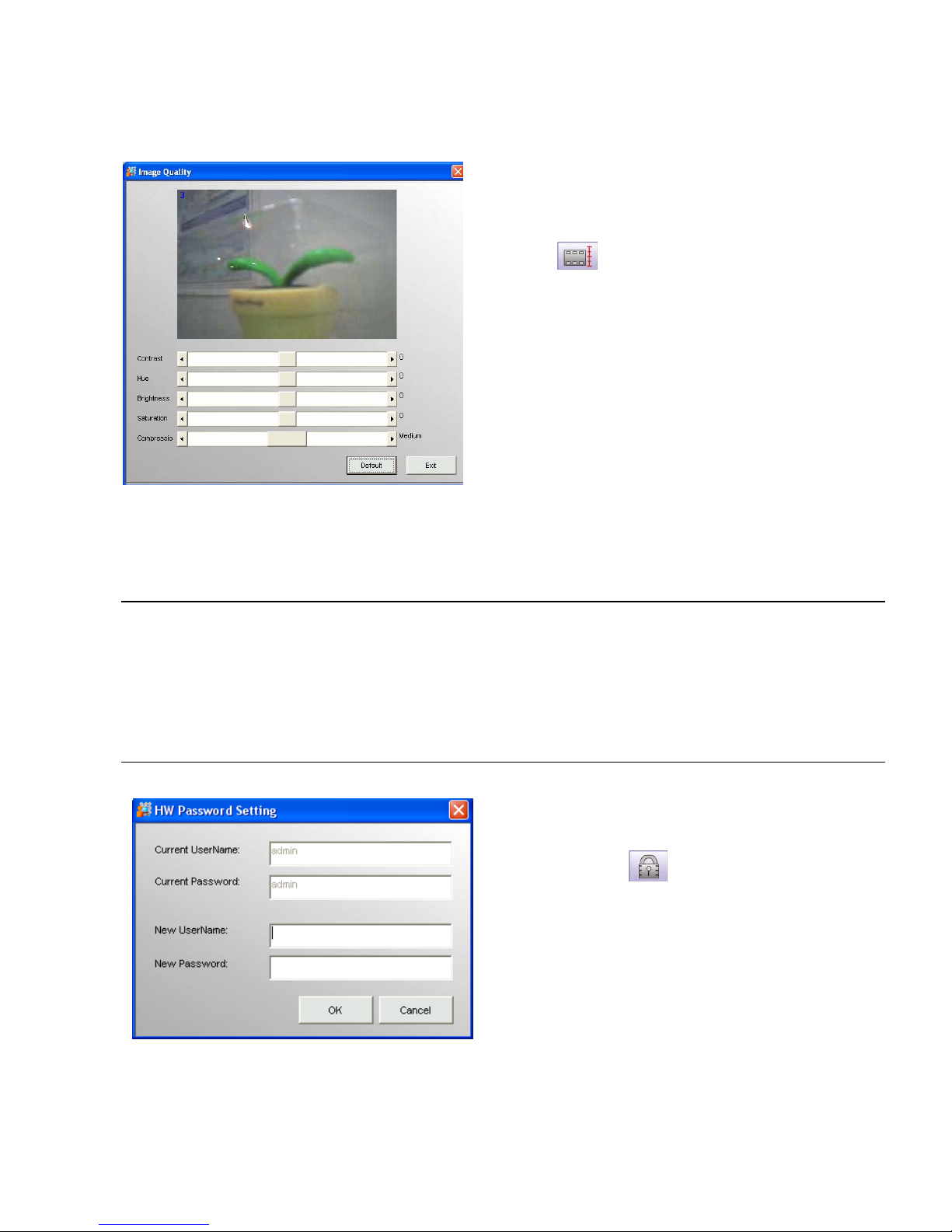
Image Quality
Select the Image icon of a Network
Camera/Video Server in the System
Setup area, and click Image Quality
button from the Menu Bar to bring
up the Image Quality window.
【Note】 Reset button is activated while
select camera image under Network
Camera/Video Server, by clicking this
button to get the real time Image Quality.
User may drag the scroll bar to right or left direction for your viewing preference and get real
time quality.
D.5.8.1.3. Remove Network Camera
Click the Remove Network Camera button to remove the video node. You will be asked to confirm
the removal. If you had dragged this video source to the e-map, the icon of this camera in the
e-map will also be removed.
D.5.8.1.4. HW Password
【Step1】Select the device icon in the
System Setup area, and click HW
Password button from the Menu Bar
to bring up the setting window.
Current UserName/Password:
The default value for current username and
current password is same as device default.
New UserName/Password:
Change information and save to both SVP
Express and Web configuration of selected
device.
【Step2】Click OK to save the setting.
Page 41
Page 35
【Note】When to configure?
SVP Express system default are same as device default, only when you want to change
PW from SVP Express or when you find the PW of device has been changed in web
configuration program
D.5.8.1.5. Sensor (Digital Input)
Many video gateways and LAN cameras has GPIO port. The digital inputs can be connected to
sensors, while digital outputs can be connecting to relay switches.
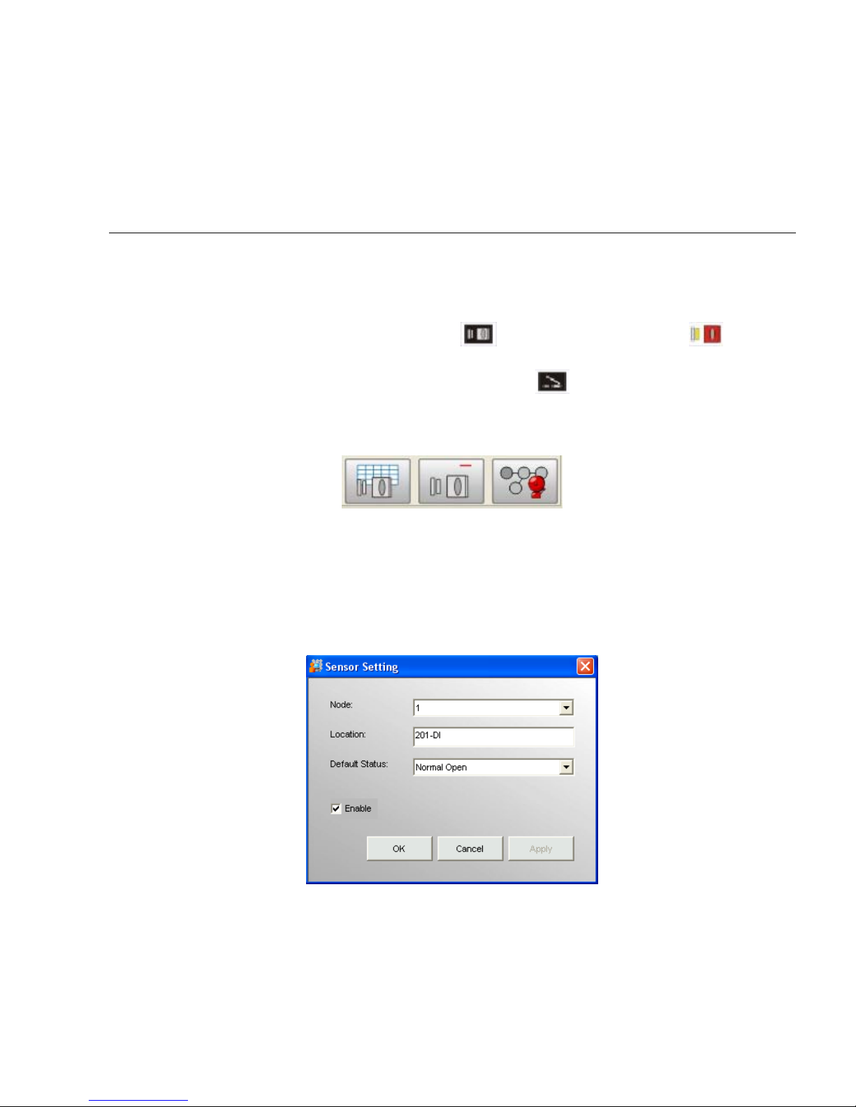
In System Setup tree, a sensor is represented by (un-configured sensor) or
(configured sensor) icon, and relay switch is represented by icon.
When you select a sensor in the System Setup tree, the toolbar becomes:
But the two buttons on the right will appear only after a sensor has been configured.
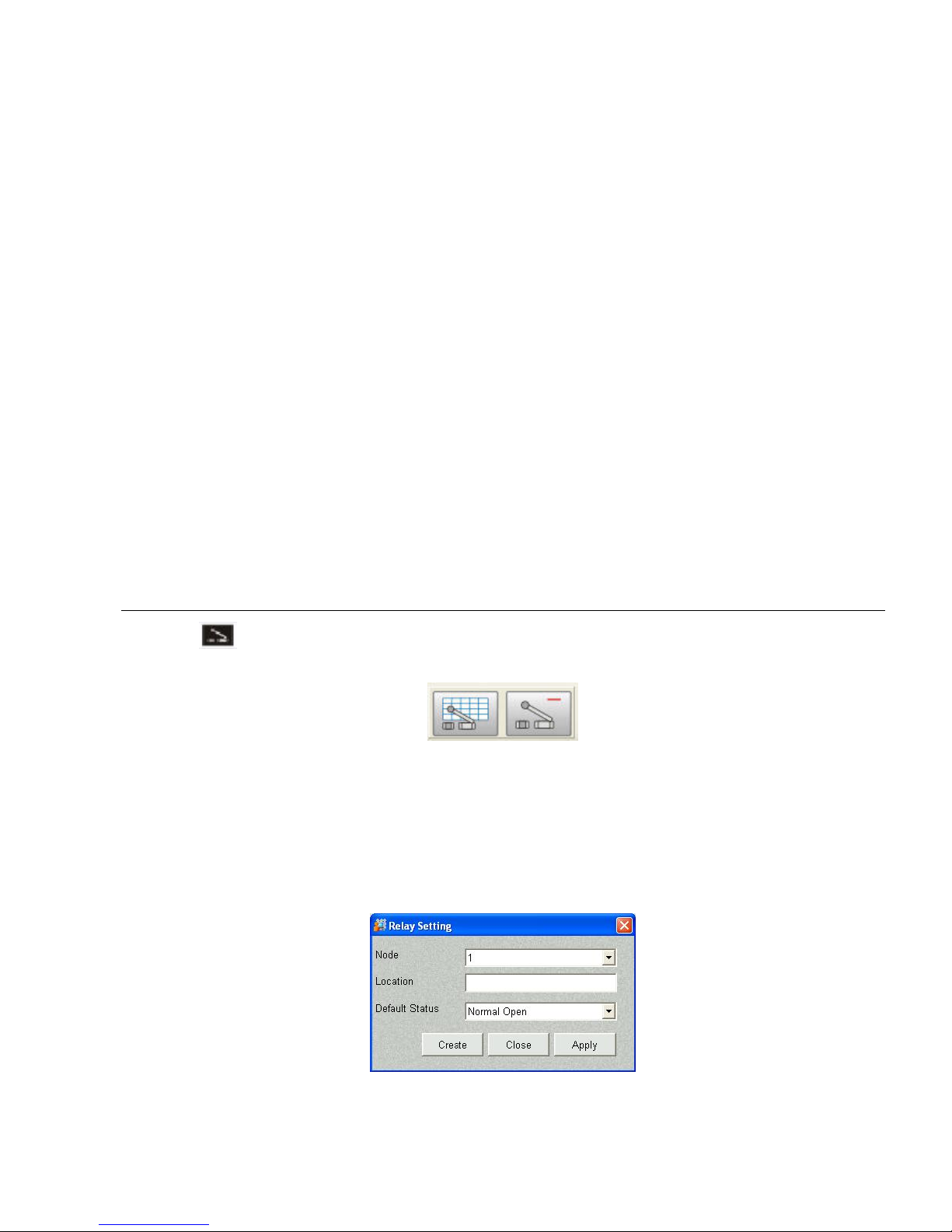
Sensor Setting
Click the [Sensor Setting] button to bring up the Sensor Setting dialog, as shown below:
1. Node: is the serial number of this sensor of the current device.
2. Location: give a meaningful name to this sensor.
Page 42
Page 36
3. Default Status: can be normal open or normal close depend on the sensor type.
4. Enable: check this to activate the sensor.
5. Click [OK] to save the settings and leave this dialog.
6. Click [Apply] to save the settings of this sensor, and stay in this dialog to set the other sensor
nodes.
Remove Sensor
Click [Remove Sensor] to remove the selected sensor. You will be asked to confirm the deletion.
Sensor Alarm
The alarm actions are the same as those for LAN camera, with two additional alarm actions:
[Enable DI] and [Disable DI]. Please refer to section D.5.8.1.2. – Image Alarm for detail setup
procedures.
D.5.8.1.6. Relay (Digital Output)
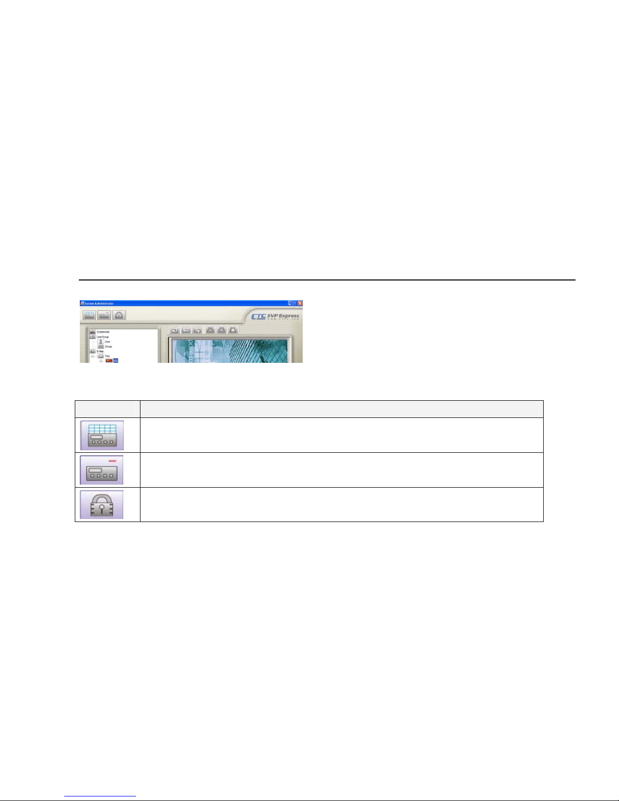
Click the button in the System Setup tree, the toolbar becomes:
The button on the right will only appear if you select a configured relay.
Relay Settings
Click [Relay Setting] button and the Relay Setting dialog will appear, as shown below:
1. Node: is the serial number of this relay on the current device.
Page 43
Page 37
2. Location: give a meaningful name for this relay.
3. Default Status: set the default status of this relay.
4. Click [Create] to save the configuration and leave the dialog, or click [Apply] to save the
configuration and continue to set another relay on the current device or modify current setting.
Remove Relay
Click the [Remove Relay] button to remove the selected Relay. You will be asked to confirm the
deletion.
D.5.8.2. Video Server
When the Video Server icon is selected in the
System Setup area, the buttons displayed in
the Menu Bar are changed as following. For
video server setting, please refer to Network
Camera setting.
Button Function
Video Server Settings: Allows you to modify the settings of the selected
video server.
Remove Video Server: Allows you to remove the selected video server,
including the cameras and other devices under it.
HW Password: to change the User Name or Password of selected Video
Server from SVP Express or to sync with the direct change in device.
Page 44
Page 38
D.5.8.3. Tools in Menu Bar of eMap interface
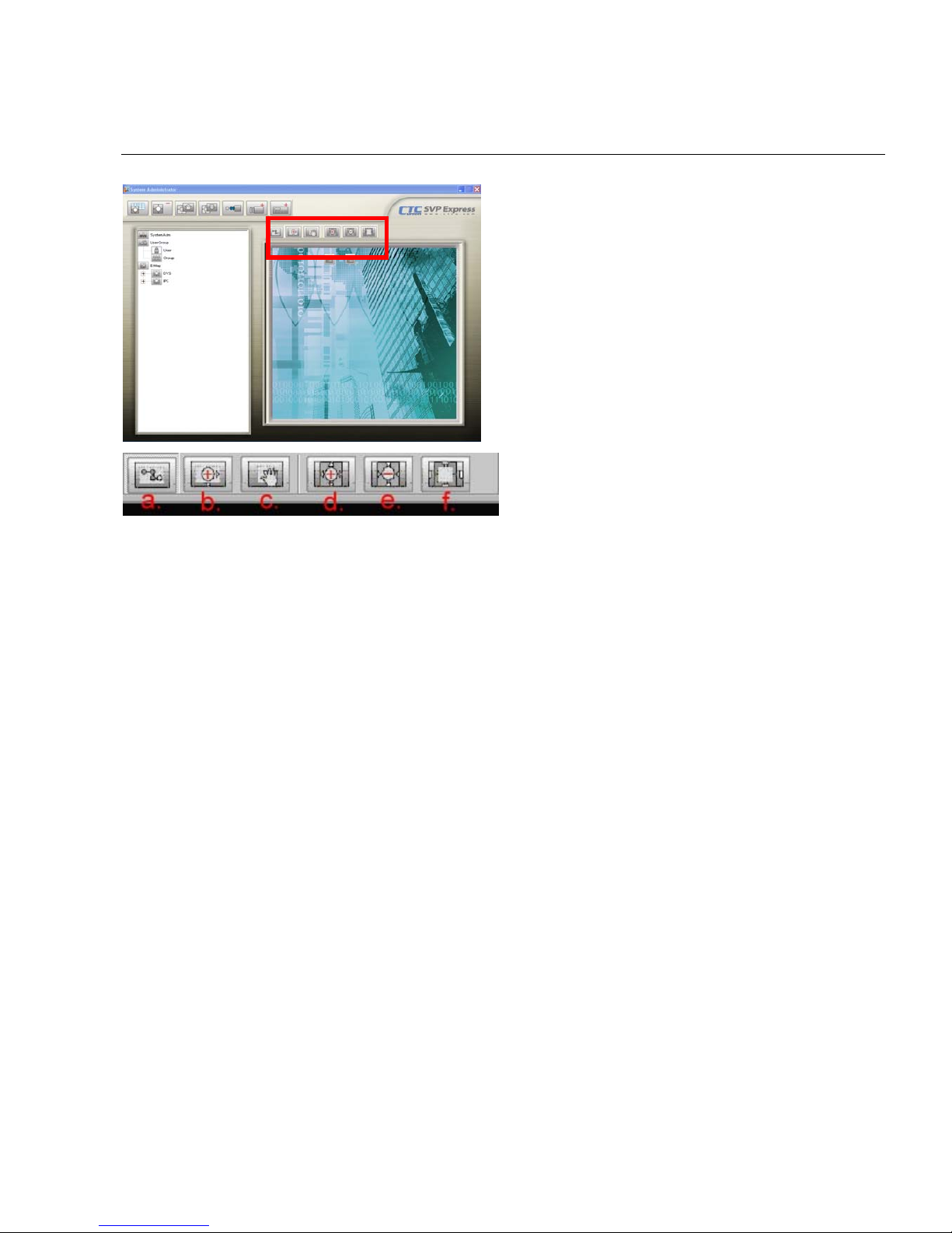
eMap tools bar will appear above the eMap
Interface area after the picture that you
uploaded to the eMap Interface area.
The tools of eMap interface could be used to control the EMap background as following:
(a) Pointer:to drag the device icon on the interface
(b) Area Zoom:to enlarge background from the specified area selected by mouse
(c) eMap Shift:to move the background
(d) Center Zoom In:to enlarge background from the center
(e) Center Zoom Out:to downsize background from the center
(f) Default Size:back to the default size and location
Page 45
Page 39
E. Monitor Program
SVP Express Monitor program could be selected from the Program Path; user may log on monitor
program through Monitor.exe or Web monitor. You may access SVP Express server thru IE
browsing by entering the URL. (Format is: IP address of server and \UniArgusShare. Example
are:127.0.0.1\UniArgusShare)
E.1. Running Monitor Program
【Step1】Select Start/All Programs/CTC
Union-SVP Express/Monitor.exe
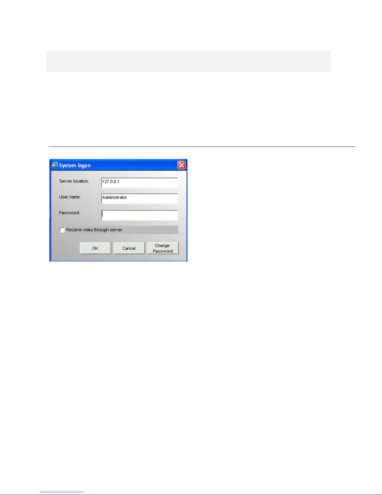
【Step2】System Log on window. If this is the
first time you login, use Administrator as
default user name and leave the password
blank, then click OK to log into the system.
Server Location: “127.0.0.1” is the default
for local server. If you want to access from
client PC, then please enter the IP of server
PC to this field.
Receive Video through Server: if you want
to remote control SVP Express server from a
client which is not within intranet, then check
this box, so that you can remote monitoring in
internet environment.
【Note】Password: It is recommended that
you change this default password, for user
restriction please go to User Group section to
change the password.
Page 46
Page 40
E.2. Monitor Program Interface
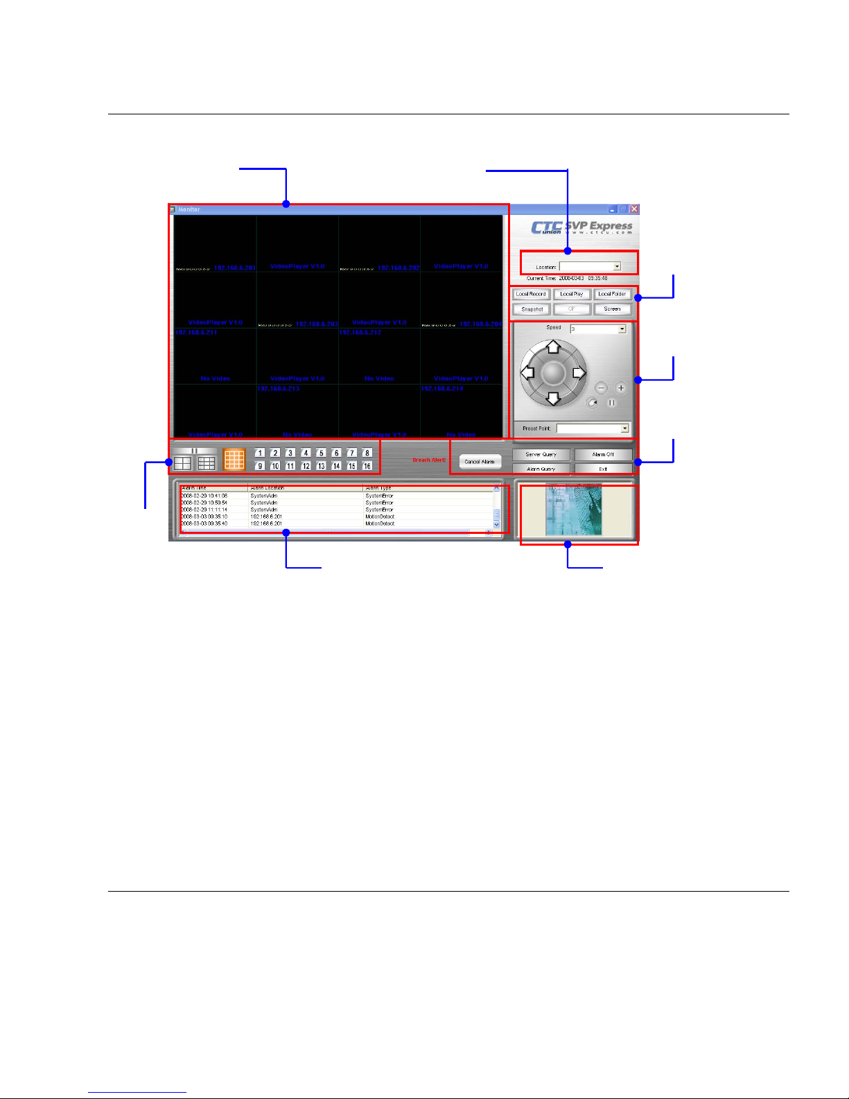
The User Interface has been classified into the following functions:
z Video Display Area
z Display Selection
z Alarm Notification Log
z Camera Selection
z Local Video Setting
z PT Control interface
z System Setting
z Alarm eMap
E.3. Video Display Area
Video display area display video of single camera or split screen of multiple cameras, when you
want to control a camera in your monitor program, you may click the split-ed screen and it will be
covered by a red-frame.
Alarm Notification Log
System
Setting
Local
Video
Setting
Alarm eMap
PT Control
Interface
Camera Selection
Video Display Area
Display
Selection
Page 47
Page 41
E.4. Camera Selection
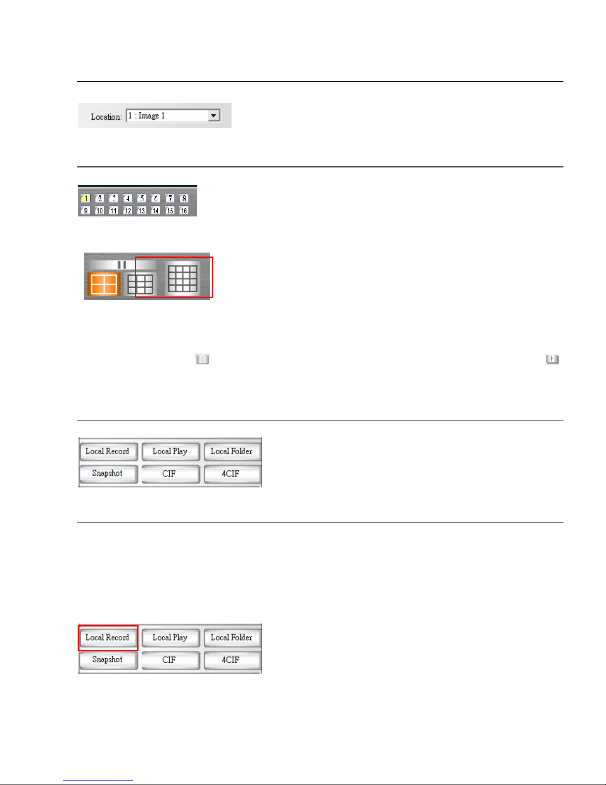
Select the camera location by clicking the drop list.
E.5. Display Selection
Display Selection (Video of Single Camera)
Select camera button in Display Selection.
【Note】The number of camera varies according to
the registration status.
Display Selection (Split Screen of Multiple Cameras)
Select split screen in Display Selection, the video display
area will change the video accordingly.
【Note】D ouble click the selected screen in S p lit screen, the split screen will change to
single display mode.
Pause the live video
Click the pause button , the live video will be paused and the button change to play button ,
for user to click to get the live video back.
E.5. Local Video Setting
E.5.1. Local Record
Live video could be manually recorded in the local computer by clicking the Local Record button,
so that user could record live video easily and save in any local computer.
Start Local Record
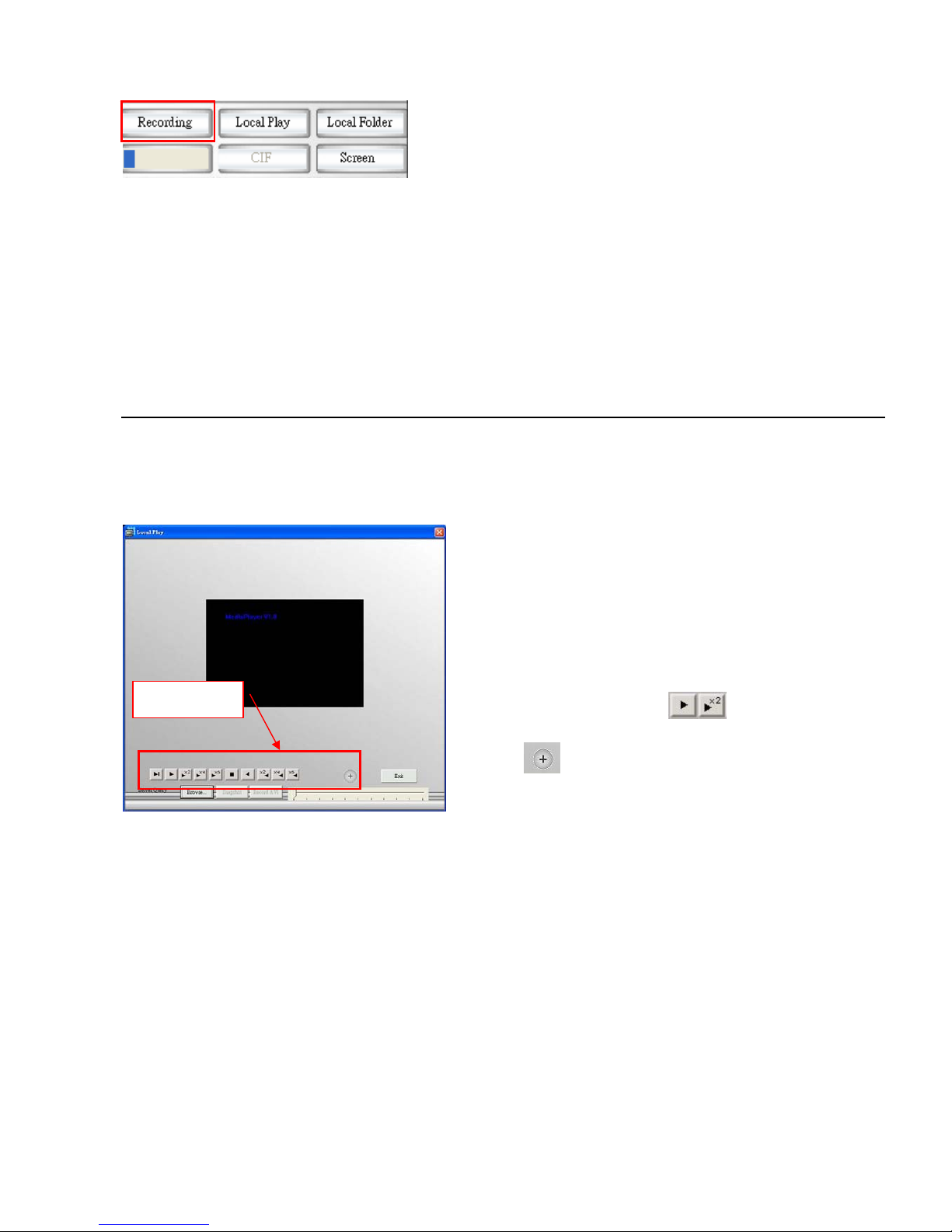
【Step1】Select a camera from display area by
a red frame.
【Step2】Click “Local Record” button to start
the recording.
Page 48
Page 42
The text of the button will change from Local
Record to Recording. The maximum of Local
Record is 15 minutes and recording status will
display in the Process Bar.
Stop Local Record
Click the Recording button. The text of the button will change from “Recording” to “Local Record”.
The Process Bar will disappear.
【Note】The path of Local Record has no storage recycle service, because Local Record could be
executed in whatever CLIENT PC which is out of Server Management scope.
E.5.2. Local Play
The Local Play button allows you to playback recorded video through “Local Record” at
local PC. This function also provides additional functions for exporting video files to the AVI
format and taking snapshots.
Basic Operation
【Step1】Open the Local Play window.
【Step2】Browse a file
Browse the file you want to display.
【Step3】Play a file
You may also select playback speed by
selecting different button
Click to full screen display.
Snapshot
Click “Pause” button to get a still image first, then click “Snapshot” button to save the image
in JPG format (please refer to Section D.5.4. Snapshot)
Transfer to AVI
Click the “Record AVI” to export the image to the AVI format. Assign a file name, a location,
and a vide compression option.
【Note】The available compression format varies according to computers, depending on
the Codec application components installed, operation system and Media Player version. If
you require the best image quality, choose the “Full Screen (uncompressed)” option.
Playback
Page 49
Page 43
E.5.3. Local Folder
Click “Local Folder” button, system will bring up “Local Directory Setting” window for user to select
the local recording folder. System will create a sub-folder differentiate by camera location
automatically.
E.5.4. Snapshot
Saves snapshot of selected video source in JPEG format. Follow below instruction:
【Step1】Select a camera from Video Display Area.
【Step2】Click “Snapshot” button to get a still image of the camera.
【Step3】Click the “Save” to save a still image in your computer by .jpg format.
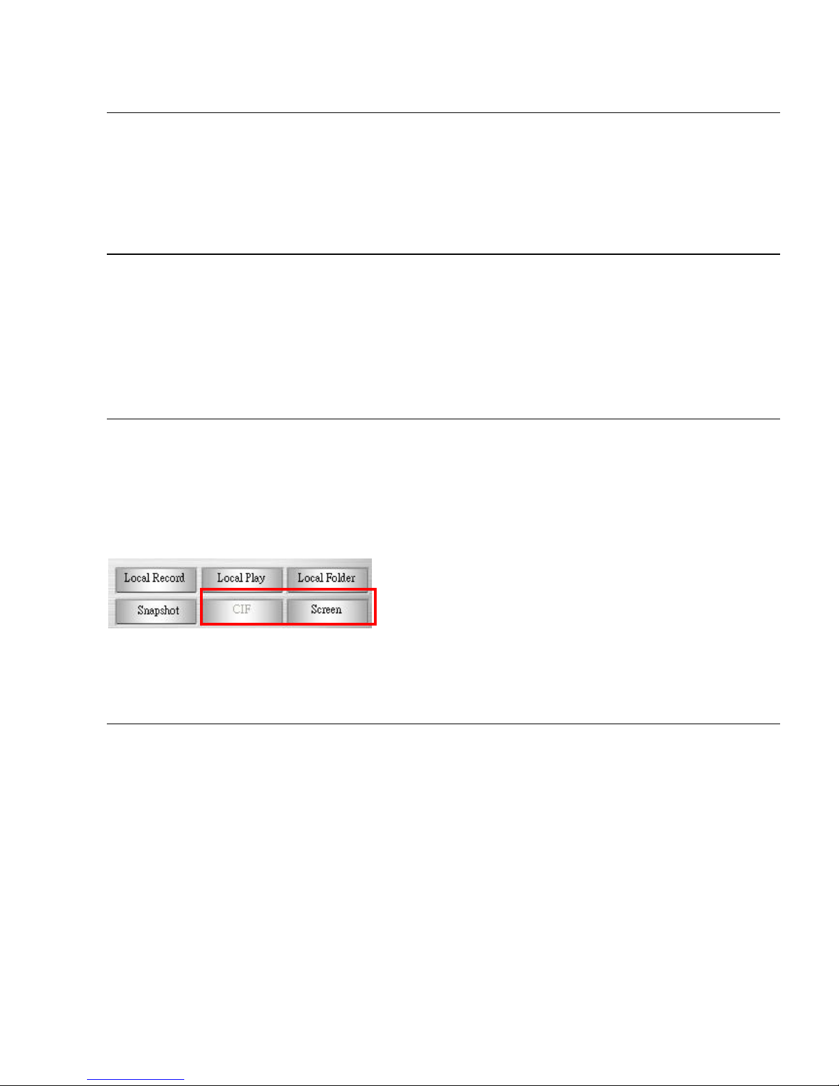
E.5.5. Resolution switch while Single camera (CIF/4CIF)
While video display in a single mode (only one video display in Video Display Area), or
the select video from the split screen, you may click CIF or 4CIF button to change
resolution to 352x240/320x288(NTSC/PAL) or 704x480/704x576 (NTSC/PAL).
(CIF/4CIF/Screen display: SVP Express resolution button will change text according to
the device resolution setting.
While video display in split screen, the
resolution button will change to CIF and
Screen respectively, while click Screen, it
display Screen of selected camera.
E.6. PT Control Interface
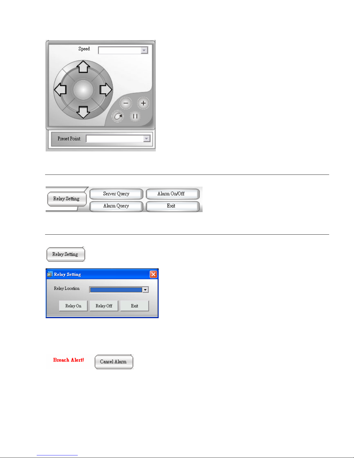
If your IP camera or analogue camera under Video Server has PTZ function, you may use SVP
Express control interface to view different angle of Camera by clicking button on PT Control
Interface.
Page 50
Page 44
1: PT Speed: You may select the drop list to
change speed of camera movement.
2: PT control: PT interface consist of a control
icon which can change view angle of your
camera to 4 directions manually.
3: - (Zoom out):to get PT camera zoom out.
4: + (Zoom in):to get PT camera zoom in.
5: AutoPan: to get PT camera auto panning.
6: Stop: to stop PT camera’s auto-action.
7: Preset Point: by this drop list, you could
select preset point (Preset point is configured
in Admin program).
E.7. System Setting
E.7.1. Relay Setting/Cancel Alarm
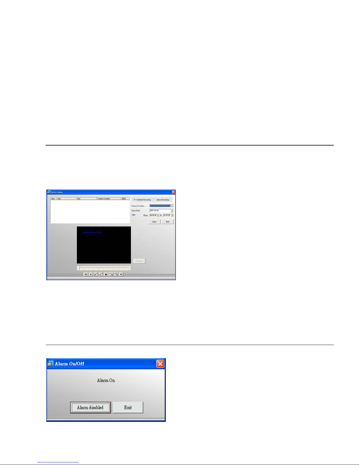
【Step1】Click “Relay Setting” button
【Step2】Select the “Relay Location” to
remote control Digital Output (light, for
example, via Internet) to on or off. Control
facility via “Relay Setting” may involve
electronic danger, please consult your
system integrator and get their professional
support.
【Note】 “Relay Setting” button use the same button of Cancel Alarm, the text varies
according to alarm status.
【Step1】Disable a System Alarm
When a “Breach Alert” message appears at the bottom of
the Video display area, an alarm has occurred and warn
user by following methods:
(1) The text of the “Relay Setting” button changed to
“Cancel Alarm”.
(2) The most up-to-date alarm was logged in the “Alarm
1
2
3 4
5
6
7
Page 51
Page 45
notification log”.
(3) An eMap with the device that triggered the alarm will
pop up in the “Alarm eMap”.
(4) Depending on how your alarm setting, a live video of
the device may pop up in the Video Display Area.
【Step2】Click the “Cancel Alarm” button to disable the “Breach Alert” message.
(1) The “Cancel Alarm” button will be replaced by a “Relay Setting” button.
(2) The alarm live video will disappear and the screen will return to its normal setting.
E.7.2. Server Query
The Server Query button allows you to playback recorded video of “Schedule Recording” or “Alarm
Recording”. This function also provides functions of exporting video files to the AVI format and
taking snapshots.
Basic Operation
【Step1】Click “Server Query” button.
【Step2】Open the window
Query Video File via criteria setting of :
z “Schedule recording“ or “Alarm
recording”
z “Image Location“
z “Query Date“.
【Step3】Click the “Query”, a query result
will appear in the upper left table.
【Step4】Select the file you want to display .
Take a Snapshot (For detail, please refer
to D.5.4. Snapshot)
Record A VI (For detail, please refer to
Section D.5.2. Local Play – Transfer to AVI)
E.7.3. Alarm On/Off
Alarm Disable/Enable
You can disable alarms when your security
staff is on duty to handle event. To do this,
click the Alarm On/Off button to
disable/enable all alarm settings in the
Administration program.
Page 52
Page 46
E.7.4. Alarm Query
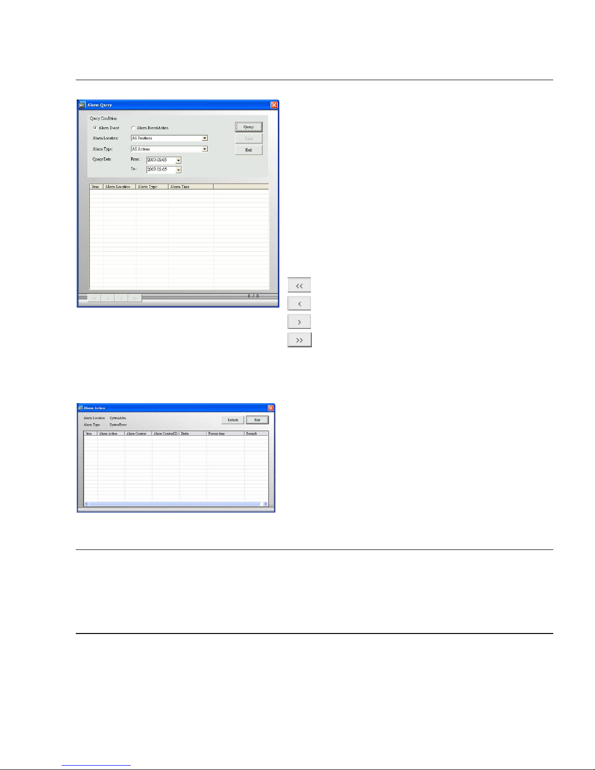
【Step1】Click “Alarm Query” button.
【Step2】Open a window to set query criteria.
Query Alarm Log via criteria setting of:
z “Alarm event” or “Alarm event/action”
z “Alarm location”
z ” Alarm style”
z “Query date”
【Step3】A query result will appear in the lower
spreadsheet. You can use the arrow button to
navigate the page of the spreadsheet, and print
the page which you selected.
:Home
:Page Up
:Page Down
:End
【Step4】You can print out the query by clicking the “Print” or “Export” button.
【Step5】Select the Export support list, assign export format and destination support. Text,
Excel and Word are all supported.
【Step6】Select an alarm log and click it to
bring up a window to get the alarm action
detail.
E.7.5. Exit
Click “Exit” to close Monitor program. This system will still be running on the background if control
program display in task bar.
E.8. Alarm eMap
An E-Map with the device that triggered the alarm will pop up in the E-Map display area.
Page 53

Page 47
E.9. Alarm Notification Log
The most up-to-date alarm was logged in the alarm notification log.
Page 54

Page 55

DVS Series
CTC Union Technologies Co., Ltd.
Far Eastern Vienna Technology Center
(Neihu Technology Park)
8F, No.60, Zhouzi Street
Neihu District, Taipei 114, Taiwan
Phone:(886) 2.2659.1021 Fax:(886) 2.2799.1355
E-mail: [email protected] Url:http://www.ctcu.com
 Loading...