

Page 1
OPERATION MANUAL
Page 2

Page 3

Table of Contents
i
CHAPTER 1
1.0 Introduction ..................................................................... 1
1.1 Features ………………………………………………….. 1
1.2 Specifications ................................................................... 2
1.3 Configuration ................................................................... 4
1.4 Configuration with Telnet ................................................. 8
1.5 Raw Data Server Mode .................................................... 9
1.6 Telnet IAC Data Server Mode ......................................... 16
1.7 Terminal Server Mode .................................................... 17
1.8 Auto Connect After Power Up Mode .............................. 20
CHAPTER 2
2.0 Application Examples ...................................................... 23
2.1 Raw Data Server Application ....................................... 23
2.2 Terminal Server Application ........................................ 24
2.3 Auto Connect Application ........................................... 26
APPENDIX
A.1 RS-232 Port Pin Definition ............................................. 29
A.2 RJ-45 Ethernet Pin Definition ......................................... 29
A.3 Null Modem Cable Pinout ............................................... 30
Page 4

Table of Contents
ii
This page left blank intentionally.
Page 5

Chapter 1: Configuration and Operation
1
1.0 Introduction
The STE-10 Serial Access Unit is a low cost, compact, serial
access server or terminal server for connecting asynchronous serial
devices (RS-232) over Ethernet (10Base-T) using a TCP/IP protocol
stack. The STE-10 may operate in either a client mode or as a server,
allowing connection of serial data directly over a LAN or WAN.
Configuration may be performed either via the DB25 pin RS-232 port
with an ASCII terminal or via Telnet and Ethernet connection on the
RJ-45 LAN port. The serial port is DTE, which allows direct
connection to DCE equipment such as Modems. For connection to
other DTE equipment such as a PC or terminal, a NULL Modem or
crossover cable is required. One is provided with the unit.
1.1 Features
• Low cost, compact design.
• Serial connection over Ethernet.
• Operates in either server or client mode.
• Complete TCP/IP protocol stack (OSI Network Layer 3).
• Provides packetization of serial data.
Page 6

Chapter 1: Configuration and Operation
2
1.2 Specifications
Hardware
• CPU Intel® 80188
• ROM 256K bytes Flash
• RAM 256K bytes DRAM
• LAN Interface IEEE802.3 10Base-T Ethernet, RJ-45
connector, DTE connection straight to HUB
• Serial interface EIA RS-232 ASYNC, DB25M connector
• Baud rates 1200, 2400, 4800, 9600, 19200, 38400,
57600, 115200, 230400, or 460800
• Data length 5, 6, 7, or 8 bits
• Parity None, Odd, or Even
• Stop bits 1 or 2 bits
• Handshaking None, RTS/CTS, or Xon/Xoff
Software
• Flash ROM Boot without network host; provision for easy
software upgrades
• Protocols TCP/IP, ARP, ICMP protocols
• Functions Telnet / Reverse Telnet
• Configuration Telnet or ASCII terminal direct or via Dial-in
• LED indicators Power, LAN Tx/Rx, Serial Tx and Rx
Page 7
Chapter 1: Configuration and Operation
3
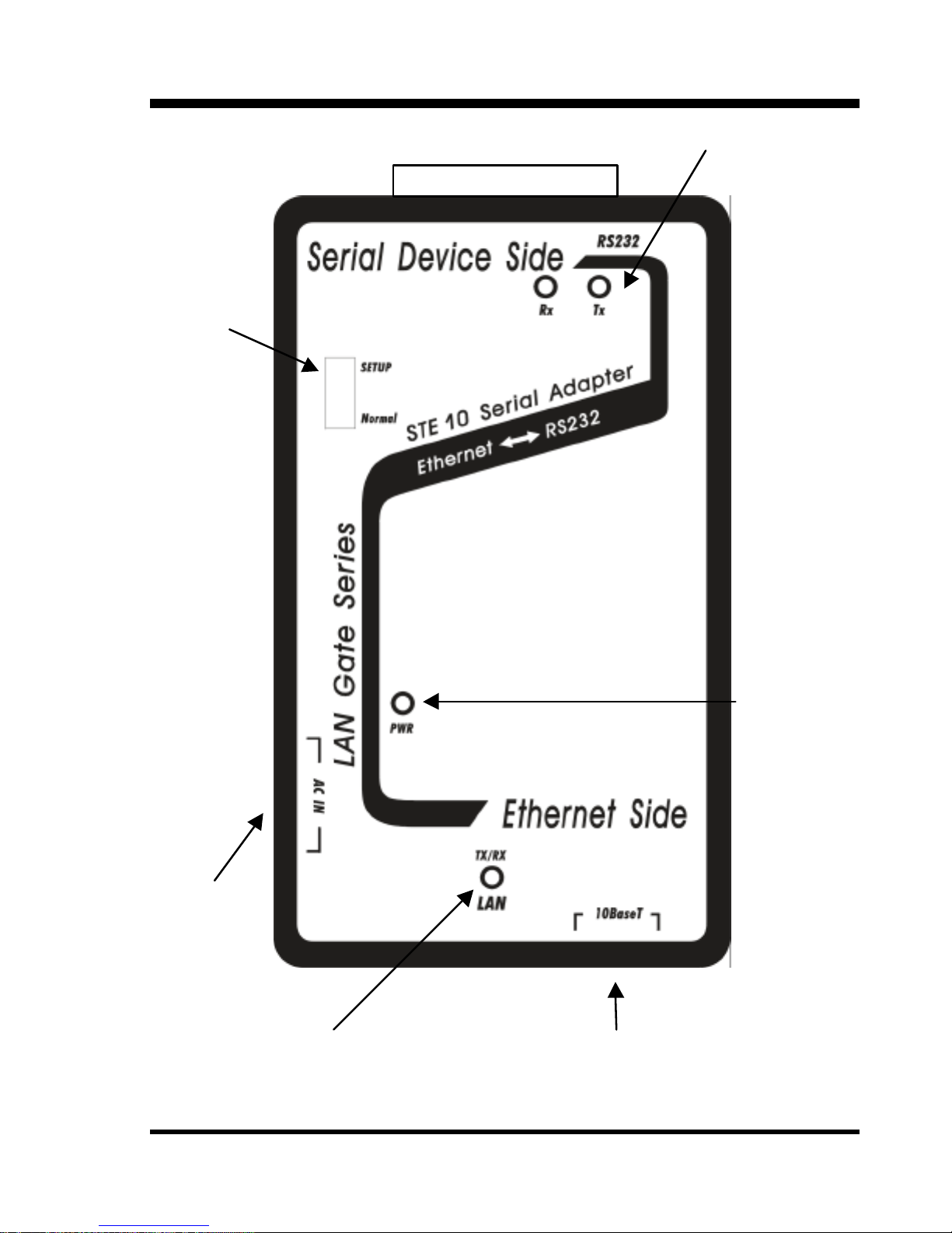
Ethernet connection: straight cable to HUB,
crossover cable to NIC
Ethernet activity indicator LED
Connect to
AC Adapter
Power
indicator
LED
RS-232 activity
LED indicators
RS-232 Async Port
D-type 25 pin Male
Config.
Switch
Page 8

Chapter 1: Configuration and Operation
4
1.3 Configuration
Before any Ethernet connection is made to the STE-10, the
device must have a valid IP address, which is accessible through the
network. Initial IP setting is accomplished with a terminal connection
to the RS-232 serial port. Connect a serial terminal to the RS-232 port
of the STE-10 at 9600 baud, 8 bits, no parity and 1 stop bit. Since the
STE-10 is DTE and a terminal is also DTE, please use the provided
crossover cable. Set the configuration switch on the STE-10 to
"SETUP" and apply power.
If a serial terminal is not available, a PC with Windows may be
used along with the HyperTerminal program. To start and configure
HyperTerminal follow these simple steps:
Using your mouse, browse to HyperTerminal; Start =>Programs
=>Accessories =>Communications =>HyperTerminal.
Double-click the "Hypertrm.exe" icon. Enter a name (such as
STE-10) and choose an icon for the connection. When the "Connect
to" dialogue box appears, click the down arrow on the "Connect
using:" pull-down tab and select "Direct to COMx" where "x" is the
COM port number that will connect to the STE-10.
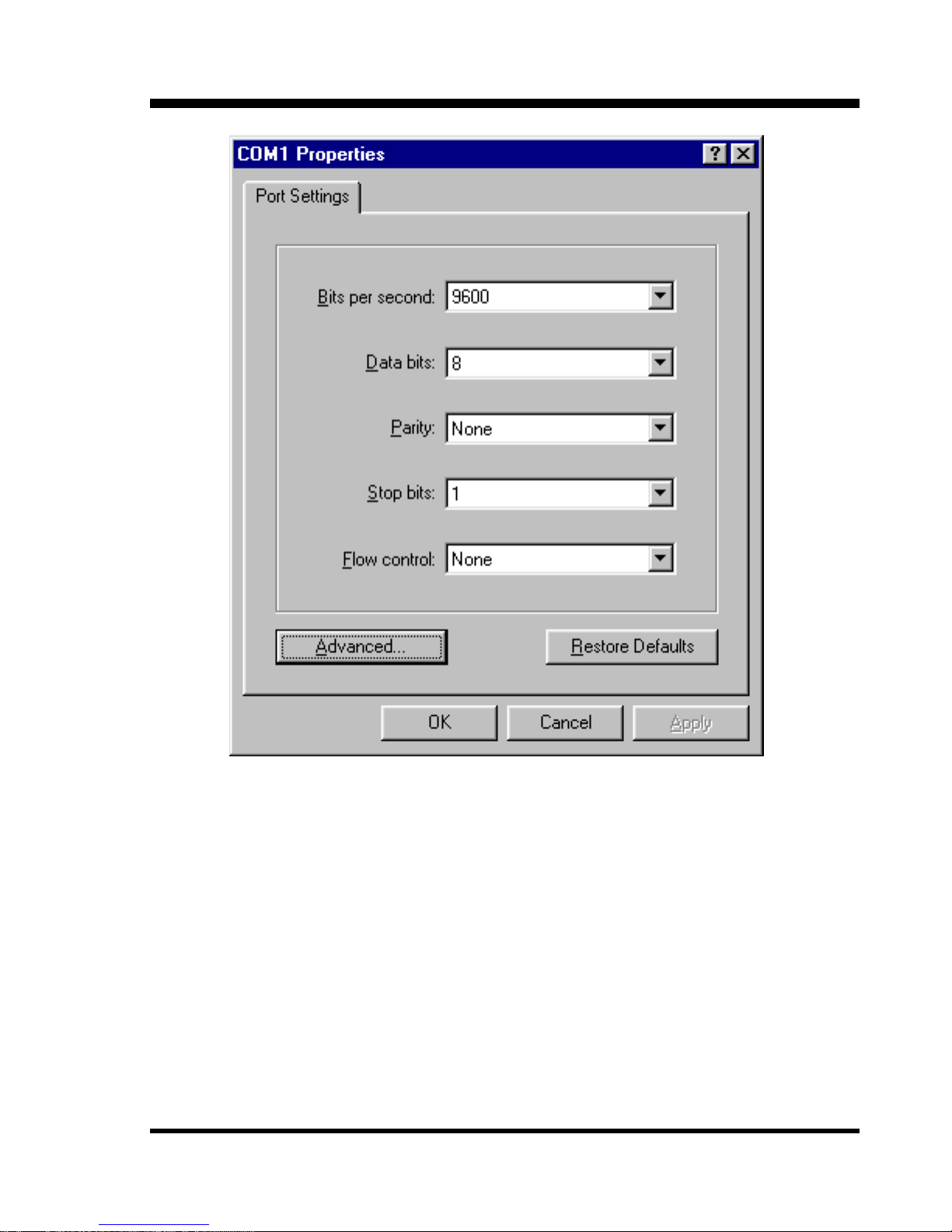
Click the "OK" button and set the COM port parameters for; 9600
baud, 8 bits, no parity, 1 stop bit and no flow control. Refer to the
following page graphic.
Page 9
Chapter 1: Configuration and Operation
5
Example of port setting under HyperTerminal .
An initial message like the one below will be displayed while the
port checks whether it is connected to a modem, followed by the main
configuration menu display.
CHECKING MODEM ABOUT 10 SECONDCHECKING MODEM ABOUT 10 SECOND
AT&C1V1AT&C1V1
Page 10

Chapter 1: Configuration and Operation
6
If your connection is a direct one, your terminal should display
the first menu for the STE-10.
SERIAL DEVICE SERVERSERIAL DEVICE SERVER
a). DEVICE SETTINGSa). DEVICE SETTINGS
b). UPGRADE FIRMWAREb). UPGRADE FIRMWARE
c). GENERAL DIAGNOSTICc). GENERAL DIAGNOSTIC
SELECT:SELECT:
Main configuration menu, terminal mode.
Select option a): Device Settings
DEVICE SETTINGSDEVICE SETTINGS
a). DEVICE IP ADDRESSa). DEVICE IP ADDRESS <192.168.2.1><192.168.2.1>
b). DEVICE SUBNET MASKb). DEVICE SUBNET MASK <255.255.255.0><255.255.255.0>
c). DEVICE NAMEc). DEVICE NAME <STE-10><STE-10>
d). DEVICE PASSWORDd). DEVICE PASSWORD <><>
e). MODE SETTINGSe). MODE SETTINGS <<RAW SERVER>RAW SERVER>
f). GATEWAY ADDRESSf). GATEWAY ADDRESS <0.0.0.0><0.0.0.0>
g). LOAD DEFAULT SETTINGSg). LOAD DEFAULT SETTINGS
h). APPLY AND SAVE SETTINGSh). APPLY AND SAVE SETTINGS
q). PREVIOUS MENUq). PREVIOUS MENU
SELECT:SELECT:
Page 11

Chapter 1: Configuration and Operation
7
At this point you may set the various STE-10 parameters.
a) Sets the IP address of the STE-10. Set the IP in the domain
where you will place the device. Please make sure the address does
not conflict with another device on your network.
b) Sets the subnet mask. If you are not sure, please ask your
network administrator. In most cases, a class "C" network will have
a subnet mask of 255.255.255.0.
c) Sets the device name used for IAC Do Send Location requests.
From the factory, the name will be set "STE-10".
d) Sets a device password to secure access to the configuration
screen from both a telnet host and a serial login. There is no
password set from the factory.
e) Selects the mode of operation of the STE-10. This will be
explained in detail later.
f) Sets the Gateway IP to access hosts not in the local domain. If
your network has Internet Access, this IP will be your IP router's
address. Please check with your network administrator if you are
not sure. If you will not be accessing a device outside your LAN,
you may leave this entry all zeroes.
g) Resets the STE-10 to the factory default parameters.
h) Stores the current settings into Flash memory for operation after
rebooting.
q) Sets the user back to the initial configuration menu.
Page 12
Chapter 1: Configuration and Operation
8
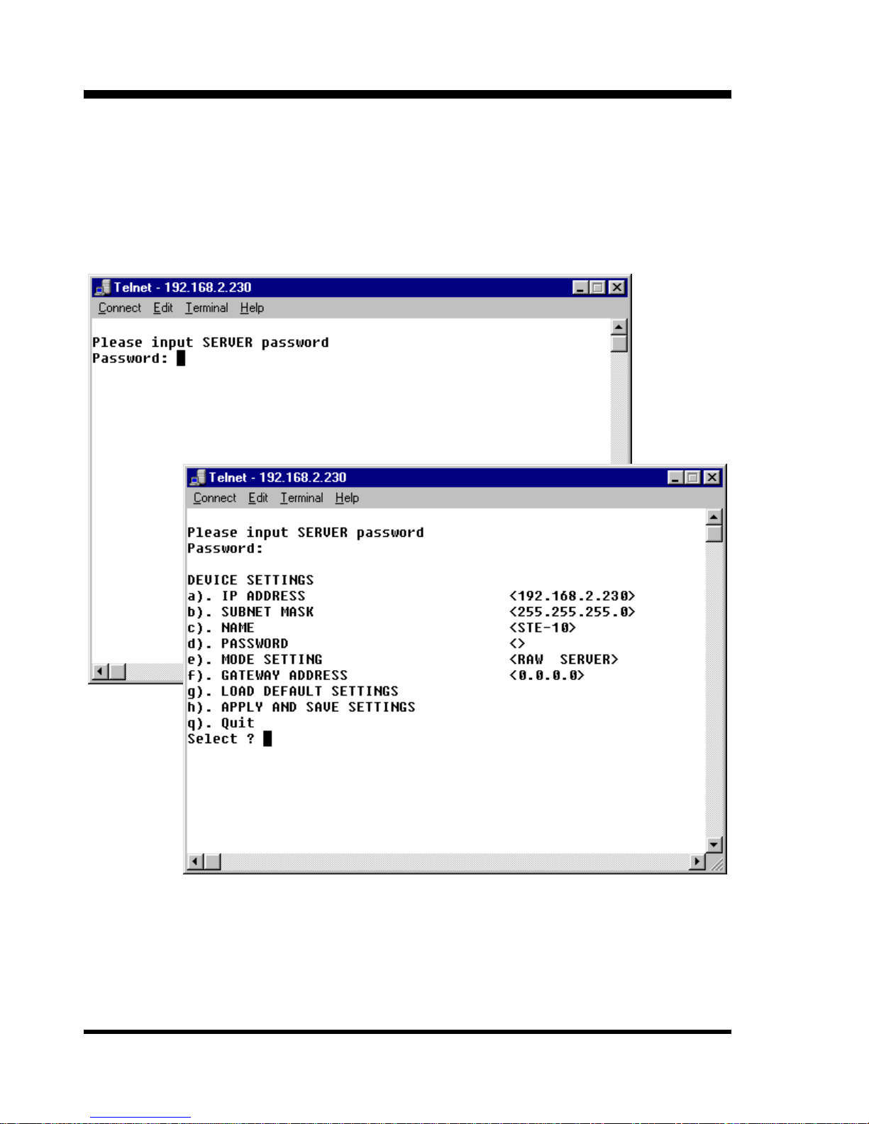
1.4 Configuration with Telnet
Once the STE-10 has a valid IP address on your network,
configuration may also be accomplished by opening a telnet
connection to the STE-10.
The same entries apply as with configuration via the serial port.
Page 13

Chapter 1: Configuration and Operation
9
1.5 Raw Data Server Mode
In Raw Data Server mode, the STE-10 accepts network
connections to the serial port with no Telnet IAC interpretation. This
mode provides a clean 8 bit data path from the host session to the
serial port. This mode is typically used for connection to data
acquisition devices. You may also use this mode to connect a Telnet
device to communicate to a serial port of a host computer, replacing a
traditional serial terminal. This example shows configuration via
terminal on the RS-232 port of the STE-10.
From the Device Settings menu, select (e),
MODE SETTINGSMODE SETTINGS
a). RAW DATA SERVER MODEa). RAW DATA SERVER MODE
b). TELNET IAC DATA SERVER MODEb). TELNET IAC DATA SERVER MODE
c). TERMINAL SERVER MODEc). TERMINAL SERVER MODE
d). AUTO d). AUTO CONNECT AFTER POWER UP MODECONNECT AFTER POWER UP MODE
q). PREVIOUS MENUq). PREVIOUS MENU
SELECT:SELECT:
Select a) RAW DATA SERVER MODE
Page 14

Chapter 1: Configuration and Operation
10
SERVER PARAMETER PORT SETTINGSSERVER PARAMETER PORT SETTINGS
a). TCP PORT NOa). TCP PORT NO <1998><1998>
b). BAUDRATEb). BAUDRATE <9600><9600>
c). DATA LENGTHc). DATA LENGTH <8 BITS><8 BITS>
d). PARITYd). PARITY <NONE><NONE>
e). STOP BITSe). STOP BITS <1 BIT><1 BIT>
f). SERIAL PORT PROTOCOLf). SERIAL PORT PROTOCOL
q). PREVIOUS MENUq). PREVIOUS MENU
SELECT:SELECT:
The SERVER PARAMETER PORT SETTINGS page provides
configuration parameters to set the TCP port number that you wish to
assign to the serial port and the characteristics of the serial port. A
normal Telnet connection will connect to TCP port number 23. This is
the method for configuration of the STE-10 via Ethernet. By default,
the TCP port number for connection to the RS-232 port is 1998.
Select a) TCP PORT NO
Modify the TCP port number if required.
Page 15

Chapter 1: Configuration and Operation
11
Select b) BAUDRATE
SERIAL BAUDRATE SETTINGSERIAL BAUDRATE SETTING
a). 1200a). 1200
b). 2400b). 2400
c). 4800c). 4800
d). 9600d). 9600
e). 19200e). 19200
f). 38400f). 38400
g). 57600g). 57600
h). 115200h). 115200
i). 230400i). 230400
j). 460800j). 460800
SELECT:SELECT:
Set the communication speed parameter to suit your
requirements.
Continue to set the remaining communication parameters. The
data length may be set to 5,6,7, or 8 bits. Parity may be set to even,
odd or none. The stop bits may be set to 1 or 2 bits.
Page 16

Chapter 1: Configuration and Operation
12
When selecting "f", the serial port protocol may be set as follows.
SERIAL PORT PROTOCOLSERIAL PORT PROTOCOL
a). FLOW a). FLOW CONTROLCONTROL <NONE><NONE>
b). RECEIVE DATA ONLY WHEN DSR ONb). RECEIVE DATA ONLY WHEN DSR ON <DISABLED><DISABLED>
q). PREVIOUS MENUq). PREVIOUS MENU
SELECT:SELECT:
From the SERIAL PORT PROTOCOL menu select "a".
FLOW CONTROLFLOW CONTROL
a). NONEa). NONE
b). RTS/CTSb). RTS/CTS
c). XON/XOFFc). XON/XOFF
SELECT:SELECT:
Select between RTS/CTS and Xon/Xoff handshaking, or none. Then,
from the SERIAL PORT PROTOCOL menu select "b".
RECEIVE DATA ONLY WHEN DSR ONRECEIVE DATA ONLY WHEN DSR ON
a). DISABLEa). DISABLE
b). ENABLEb). ENABLE
SELECT:SELECT:
Page 17

Chapter 1: Configuration and Operation
13
If this parameter is enabled, data reception is possible only when
there is a valid connection and DSR is provided.
This completes the configuration of the serial port for raw server
mode.
Select q) to return to the previous menu
Select q again) to return to the Device Settings menu
Select h) to initiate FLASH update
UPDATE EEPROM DATA:UPDATE EEPROM DATA:
STEP 1: PREPARE DATA... STEP 1: PREPARE DATA... SUCCESS !SUCCESS !
STEP 2: FLASH STEP 2: FLASH ERASE... ERASE... SUCCESS !SUCCESS !
STEP 3: WRITE EEPROM DATA TO SERVER...STEP 3: WRITE EEPROM DATA TO SERVER...
SUCCESS! <<PRESS ANY KEY... >>SUCCESS! <<PRESS ANY KEY... >>
Press any key to return to the main menu, set the switch to
"Normal" mode and reboot (power off/on). You can now establish a
TCP connection to the assigned IP address and port number. This may
be done from a DOS prompt or from within the Telnet application.
C:\>telnet 192.168.2.230 1998C:\>telnet 192.168.2.230 1998
Page 18
Chapter 1: Configuration and Operation
14
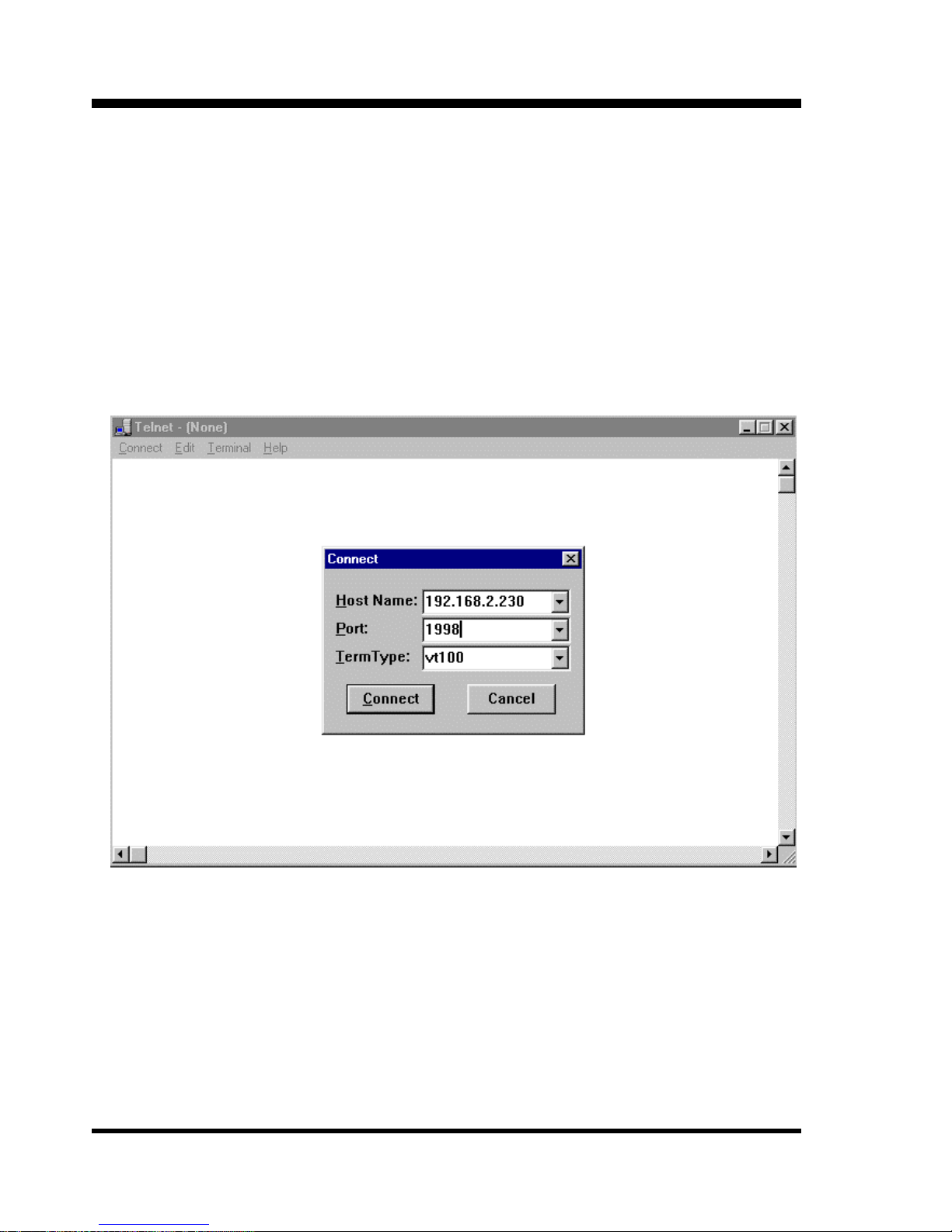
Windows includes a Telnet application that may be started by
clicking “Start” and selecting “Run”. Type in the name “telnet.exe”
and click “OK”. The Telnet application will start. From the Telnet
window select Connect => Remote System, a dialogue box will
appear. Set the IP address and Port number. Refer to the example
below.
After entering the IP address and Port number, click the
“Connect” button. The Telnet terminal will now connect to the serial
port and display just as if it were a serial terminal. If the serial device is
a data acquisition device, a host may access the device with a Telnet
connection directly.
Page 19
Chapter 1: Configuration and Operation
15
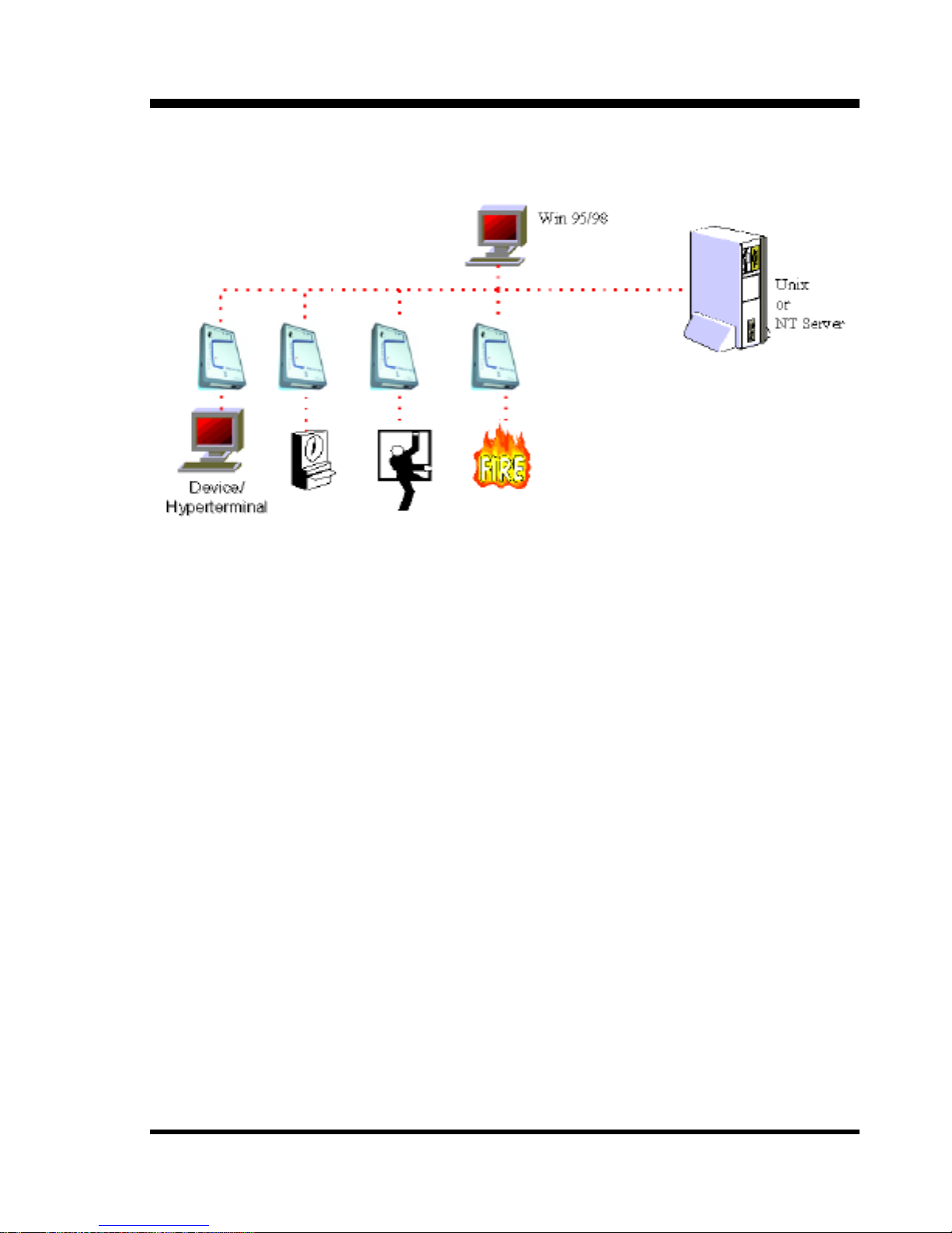
RAW vs. IAC Telnet mode
The host initiates a TCP connection to IP address:socket number.
This may be a typical UNIX session or a Winsock application for
Microsoft Windows NT or 98/95 host. The host session is then
connected to the serial port of the STE-10. In RAW mode, the path is
a clean 8 bit data path. In IAC mode, Telnet IAC interpretation is
negotiated between the STE-10 and the host.
Page 20

Chapter 1: Configuration and Operation
16
1.6 Telnet IAC Data Server Mode
At the Device Settings menu
Select e) Mode Settings
Select b) TELNET IAC DATA SERVER MODE
Enter the parameter settings in the Server Parameter Port Settings
Menu for TCPIP Port number and serial port parameters. The menus
and setup are exactly the same as for Raw Data Server mode. Please
refer to section 1.5 for details of the Raw Data Server settings.
Select q) To return to the mode setting menu
Select q) Previous Menu to return to the Device Settings menu
Select h) Apply and Save Settings
The following screen will advise you of successful completion.
UPDATE EEPROM DATA:UPDATE EEPROM DATA:
STEP 1: PREPARE DATA... STEP 1: PREPARE DATA... SUCCESS !SUCCESS !
STEP 2: FLASH STEP 2: FLASH ERASE... ERASE... SUCCESS !SUCCESS !
STEP 3: WRITE EEPROM DATA TO SERVER...STEP 3: WRITE EEPROM DATA TO SERVER...
SUCCESS! <<PRESS ANY KEY... >>SUCCESS! <<PRESS ANY KEY... >>
You may now change the switch to "Normal" mode and reboot
(power off/on). The STE-10 will boot in Telnet IAC Server Mode and
you may establish a connection from a host that will undertake Telnet
IAC interpretation.
Page 21
Chapter 1: Configuration and Operation
17
1.7 Terminal Server Mode
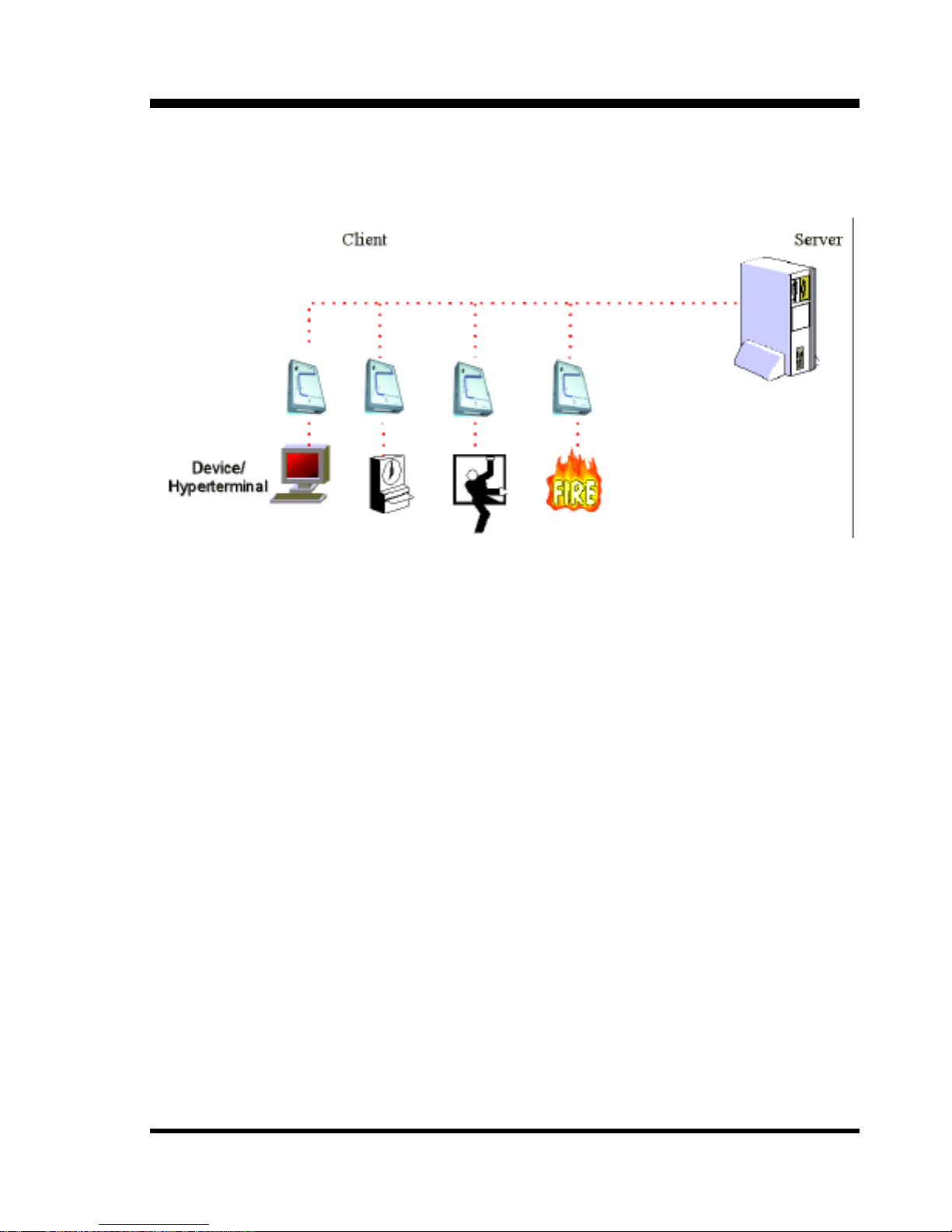
The client terminal can telnet to the host from the command line
or the STE-10 may be setup in Auto Client mode to automatically
establish a telnet connection to the host upon power up. In Terminal
Server Mode a serial device, such as HyperTerminal on a PC, may
establish a telnet connection to a host through the STE-10. The host
may be a Unix server or even another STE-10 serial port.
At the Device Settings menu:
Select e) Mode Settings ==> Select c) Terminal Server Mode
Page 22

Chapter 1: Configuration and Operation
18
The Async Port Settings menu will be displayed.
ASYNC PORT SETTINGASYNC PORT SETTING
a). BAUDRATEa). BAUDRATE <9600><9600>
b). DATA LENGTHb). DATA LENGTH <8 BITS><8 BITS>
c). PARITYc). PARITY <NONE><NONE>
d). STOP BITSd). STOP BITS <1 BIT><1 BIT>
e). SERIAL PORT PROTOCOLe). SERIAL PORT PROTOCOL
q). PREVIOUS MENUq). PREVIOUS MENU
SELECT:SELECT:
Modify the port settings to suit your requirements. The Serial Port
Protocol menu includes two extra items, “Logout When DSR Off”
and “Data Mode”. The “Logout” enabled will provide for automatic
disconnection when the serial DSR is off. For “Data Mode”, you may
select between Raw or IAC mode data.
SERIAL PORT PROTOCOLSERIAL PORT PROTOCOL
a). FLOW a). FLOW CONTROLCONTROL <NONE><NONE>
b). RECEIVE DATA ONLY WHEN DSR ONb). RECEIVE DATA ONLY WHEN DSR ON <DISABLED><DISABLED>
c). LOGOUT WHEN DSR OFFc). LOGOUT WHEN DSR OFF <DISABLED><DISABLED>
d). DATA MODEd). DATA MODE <IAC MODE><IAC MODE>
q). PREVIOUS MENUq). PREVIOUS MENU
SELECT:SELECT:
Page 23

Chapter 1: Configuration and Operation
19
When your settings are correct:
Select q) Previous Menu to return to the Mode Setting menu.
Select q) again to return to the Device Settings menu
Select h) Apply and Save Settings
You will get confirmation that the settings have been saved. Press
any key to return to the Device Settings menu.
After configuration, set the switch to "Normal" and reboot (power
off/on). The STE-10 will boot in terminal server mode and offer a
command line prompt to any attached terminal. Help will show the
available commands. Show Status will show the current settings.
STE-10>help
telnet help ? save
change speed change parity change stopbits change charsize
change ipaddress change gateway change netmask show status
STE-10>show status
speed <9600>
parity <NONE PARITY>
stopbits <1 STOP BIT>
charsize <8 BITS>
ipaddress <192.168.2.230>
gateway <192.168.2.254>
netmask <255.255.255.0>
STE-10>telnet 192.168.2.2
FreeBSD/i386 (FreeBSD.ctcu.com.tw) (ttyp1)
login:
In our example, we have made a telnet connection to a UNIX
host. The STE-10 will even access a host on a different network if the
"gateway" has been set.
Page 24
Chapter 1: Configuration and Operation
20
1.8 Auto Connect After Power Up Mode
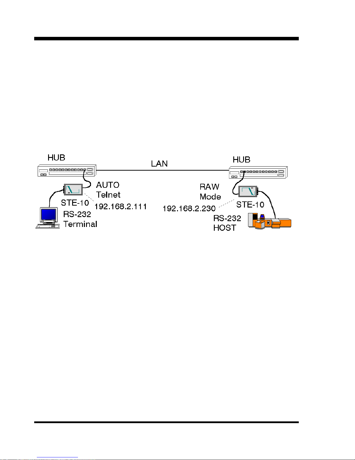
This mode is an automatic terminal server mode. In this mode the
STE-10 will automatically establish a telnet connection to the
specified IP address:socket number upon power up. When paired with
another STE-10 in “Raw” mode, a transparent RS-232 connection
may be made over Ethernet.
In the above application example, the “RAW” mode STE-10 will
establish an Ethernet link to the host’s RS-232 port. The STE-10 in
“AUTO TELNET” mode will automatically establish a Telnet
connection to the “RAW” server. The result is a transparent RS-232
path over Ethernet.
Assume that we have already configured one STE-10 in “RAW”
mode with IP Address 192.168.2.230, and have connected our host’s
serial port to the LAN network. Now configure a second STE-10 with
IP Address 192.168.2.111. Then, from the Mode Setting menu:
Select d) Auto Connect After Power Up Mode
Page 25

Chapter 1: Configuration and Operation
21
CLIENT PARAMETER PORT SETTINGSCLIENT PARAMETER PORT SETTINGS
a). REMOTE IP ADDRESSa). REMOTE IP ADDRESS <0.0.0.0><0.0.0.0>
b). REMOTE b). REMOTE PORT NOPORT NO <0><0>
c). BAUDRATEc). BAUDRATE <9600><9600>
d). DATA LENGTHd). DATA LENGTH <8 BITS><8 BITS>
e). PARITYe). PARITY <NONE><NONE>
f). STOP BITSf). STOP BITS <1 BIT><1 BIT>
g). SERIAL PORT PROTOCOLg). SERIAL PORT PROTOCOL
q). PREVIOUS MENUq). PREVIOUS MENU
SELECT:SELECT:
The Client Parameter Port Settings menu will then allow you to
specify the remote IP address and port number that you wish to
connect to as well as the serial port settings. Enter the IP address of the
remote “RAW” server and its Port number. Configure the serial
parameters accordingly and exit to the previous menu. Apply and save
the settings. Switch the device to “Normal” mode and reboot (power
off/on). The STE-10 will now automatically login a Telnet connection
to the remote STE-10 to establish your RS-232 connection over
Ethernet.
Page 26

Chapter 1: Configuration and Operation
22
This page left blank intentionally.
Page 27
Chapter 2: Application Examples
23
2.0 Application Examples
2.1 Raw Data Mode Application, control serial port of ETU01-A
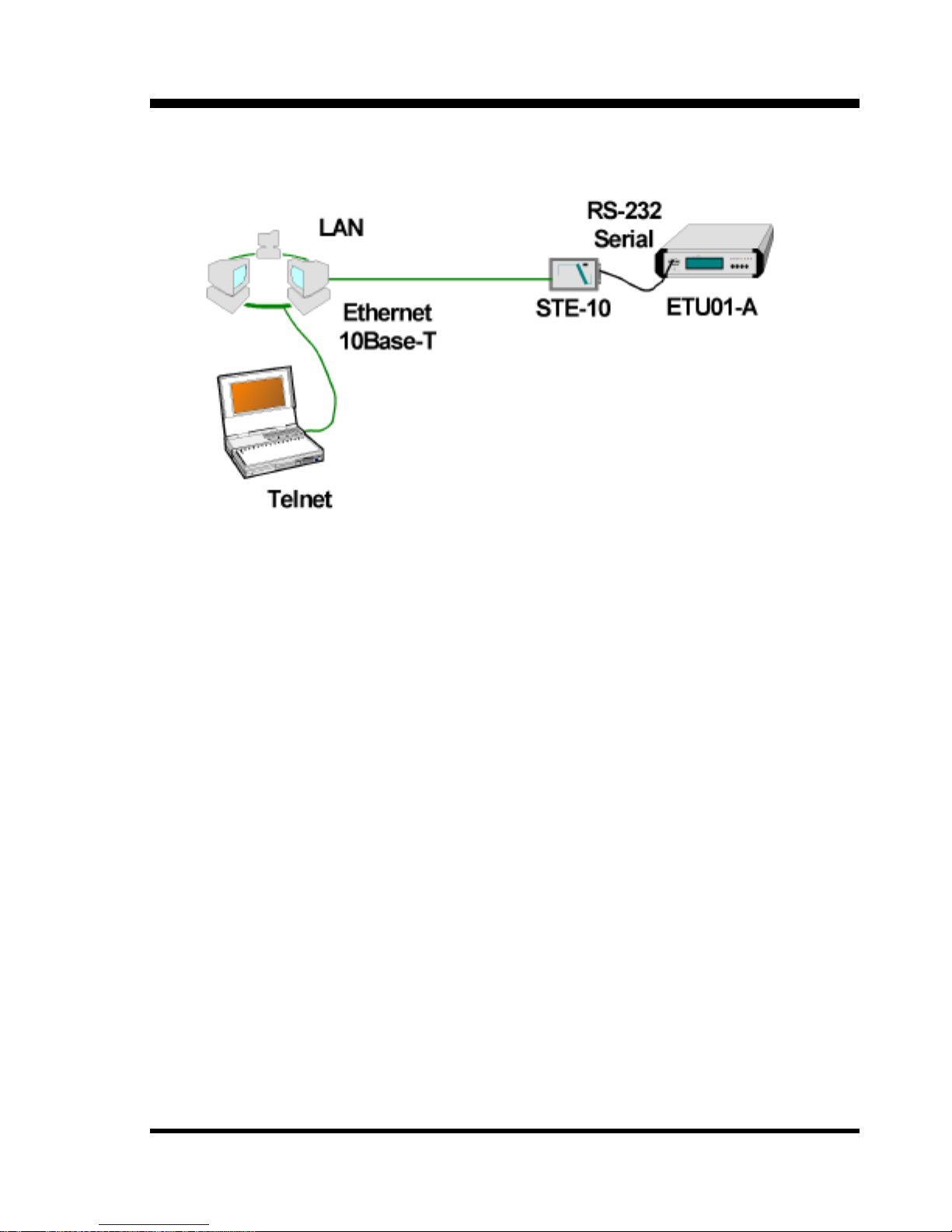
In the above example, the STE-10 provides Telnet access to the
ETU01-A's RS-232 serial control port. Using this method, the ETU01A may be controlled remotely through an Ethernet connection and
remote telnet terminal.
The configuration settings for the STE-10 are very straight
forward. Configure the STE-10 from the serial port to set IP address,
mask, gateway, etc. Set the mode to Raw Data Server and set the data
port to 9600,8,N,1 with no handshaking. Then connect the device as
shown in the above figure. The ETU01-A's control port is DCE.
Therefore, the STE-10 is connected with a straight serial connection
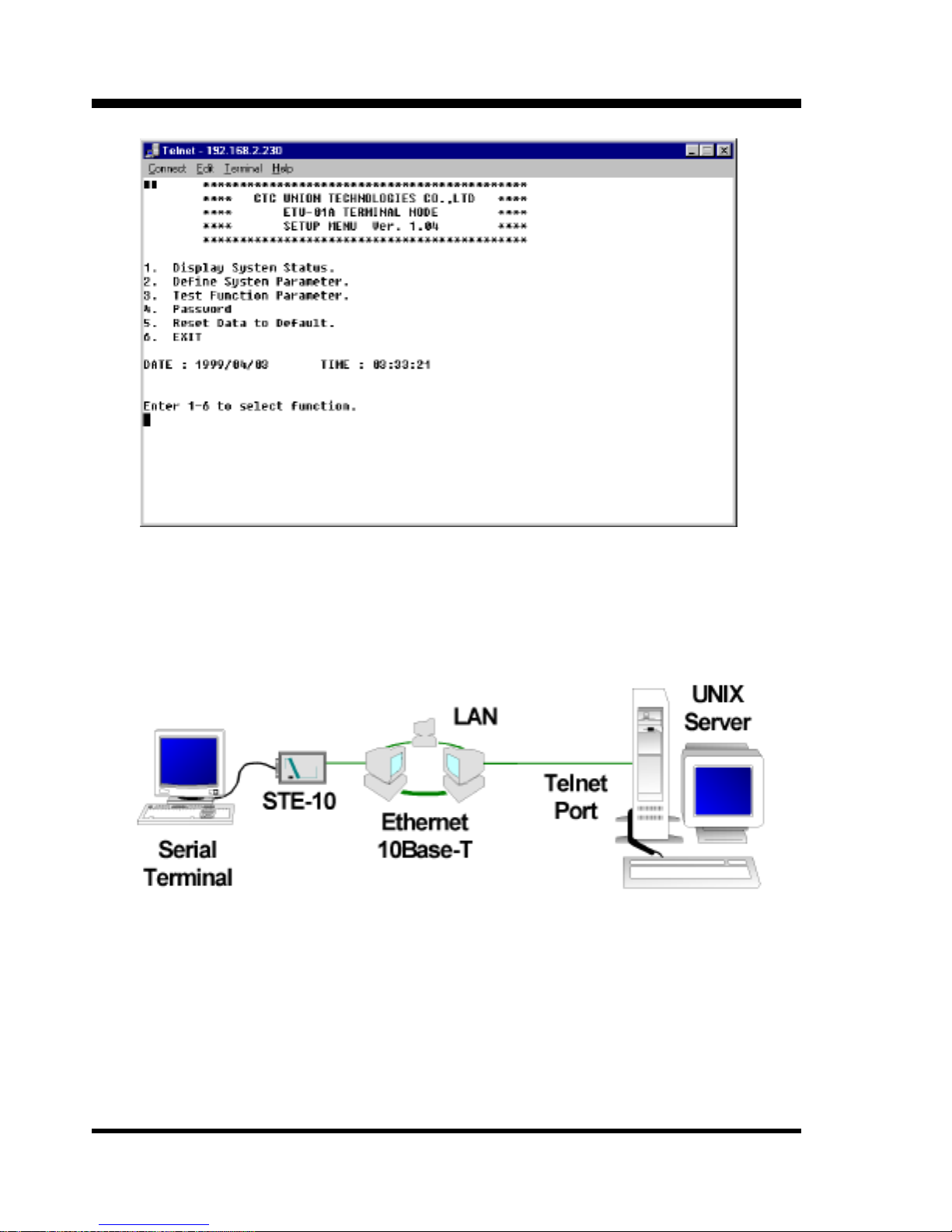
with DB25 to DB9 adapter. The next page shows an example of the
Telnet screen display when connected to the ETU01-A.
Page 28
Chapter 2: Application Examples
24
View of ETU01-A Terminal Mode via telnet connection and STE-10.
2.2 Terminal Server Application
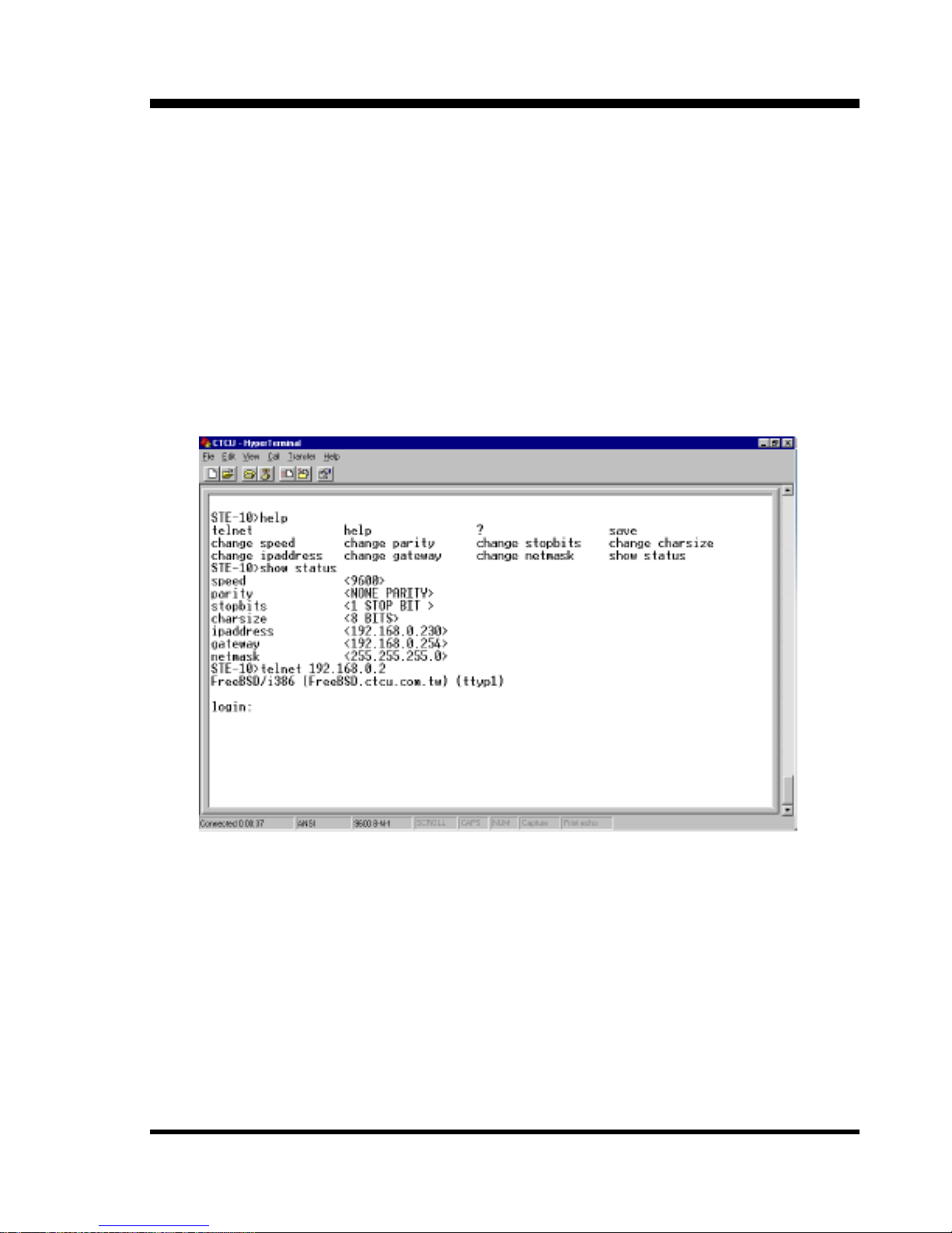
Terminal Server, allows Telnet connection via serial terminal.
Refer to the configuration setup for terminal server mode starting
in Section 1.7.
Page 29
Chapter 2: Application Examples
25
The STE-10 is assigned an IP address for the domain and the
serial port is configured according to the requirements of the serial
terminal. In our example, we used a PC with Windows, running
HyperTerminal and a serial connection on COM1. The port settings
were 9600, 8 bits, no parity, one stop bit, and no flow control. The
STE-10 provides a prompt on the terminal screen. A telnet connection
to the UNIX host is initiated. Below is the screen captured.
STE-10 Terminal Server mode, serial access to telnet.
The Raw Server mode can be used in conjunction with another
STE-10 unit running in Auto Telnet mode to provide a transparent
serial connection over TCPIP. This is the next application we will
explore.
Page 30
Chapter 2: Application Examples
26
2.3 Auto Telnet Mode Application
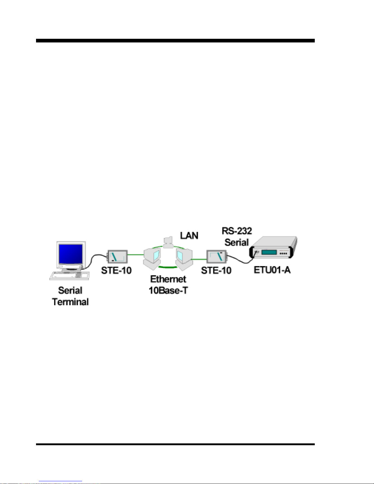
The application provides a very transparent connection for RS232 over Ethernet using the TCPIP protocol stack. In our example, we
are again connecting to an ETU01-A control port for management. The
ETU01-A side will have one STE-10 configured in Raw Mode and
connected to Ethernet. The remote terminal side will have another
STE-10 connected to Ethernet and configured to "auto" telnet to the
ETU01-A side's STE-10. The next figure is a simple example of this
application.
Auto Telnet and Raw Mode Access provides transparent connection.
The right side STE-10 unit is configured in Raw Mode, set an IP
address and port number, with serial port configured for the ETU01-A
(9600,8,N,1 no handshaking). The left side STE-10 Terminal Server is
configured in auto Telnet mode, pointing to the right side's IP address
and port number. Its serial port is configured for the serial terminal
(9600,8,N,1 no handshaking).
Page 31
Chapter 2: Application Examples
27
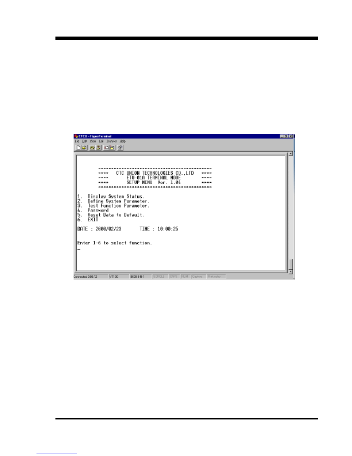
When connected together and powered on, the Terminal Server
will automatically Telnet to the Raw mode access server. A transparent
RS-232 link is established over the Ethernet medium. How's that for
RS-232 extention!! Using an Internet connection, your remote serial
device could be anywhere in the world.
Terminal display with serial connection over Ethernet.
So now we leave it up to you. If you have serial devices and
Ethernet, then the STE-10 may provide just the solution you've been
dreaming of.
Page 32

Chapter 2: Application Examples
28
This page left blank intentionally.
Page 33
Appendix
29
A.1 RS-232 Port Pin Definition
V.24/RS-232 INTERFACE PIN ASSIGNMENT
PIN CIRCUIT FUNCTION DIRECTION EIA
1 FGND Protective GND AA
2 TD Transmit data
OUT
BA
3 RD Receive data
IN
BB
4 RTS Request to send OUT CA
5 CTS Clear to send IN CB
6 DSR Data set ready IN CC
7 GND Signal ground AB
8 DCD Carrier detect IN CF
15 TC Transmit clock IN DB
17 RC Receive clock IN DD
20 DTR Data term ready OUT CD
24 XTC DTE xmit clock OUT DA
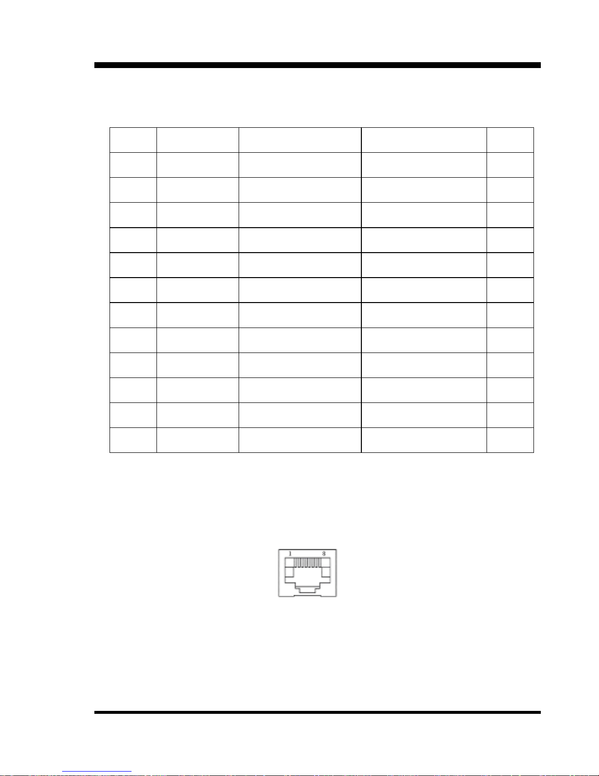
A.2 RJ-45 Ethernet Pin Definition
1 Tx (+)
2 Tx (-)
3 Rx (+)
4 NC
5 NC
6 Rx (-)
7 NC
8 NC
Page 34

Appendix
30
A.3 Null Modem Cable Pinout
DB25(Female) DB25(Female)
PIN PIN
2 <===========> 3
3 <===========> 2
4 <===========> 5
5 <===========> 4
6 <===========> 20
7 <===========> 7
20 <===========> 6
note: This cable supplied with unit. Use it to connect STE-10 to DTE
device, such as PC's COM port.
Page 35

Page 36

CTC Union Technologies Co., Ltd.
Far Eastern Edison Science and Technologies Center
(Nei-Hu HI-TEC Park)
6F-3, Lane 360, Nei-Hu Road, Section 1
Nei-Hu, Taipei, Taiwan
Phone:(886) 2.2659.1021 (Rep) Fax:(886) 2.2799.1355
E-mail: [email protected] http://www.ctcu.com
 Loading...