

Page 1

SHRM03b
G.SHDSL.bis TDM Series 4U 19" Chassis
Page 2

Page 3

CTC Union Technologies Co., Ltd.
Far Eastern Vienna Technology Center (Neihu Technology Park)
8F, No. 60 Zhouzi St.
Neihu District
Taipei 114
Taiwan
Tel: +886-2-26591021
Fax: +886-2-27991355
Email: [email protected]
URL: http://www.ctcu.com
SHRM03b TDM series 4U 19” Rack Mount Chassis
This manual supports the entire G.SHDSL.bis TDM Rack card family
SHRM03b-SH (shelf)
SHRM03b-PW (Power Module)
SHRM03b-PD ()
SHRM03b-FAN (Fan Assembly)
SHRM03b series TDM based G.SHDSL.bis Line card
SHRM03b-E1 (G.703 E1 card)
SHRM03b-V35 (Data Communications Card)
SHRM03b-ET100 (Ethernet Bridge Card)
SHRM03b-SNMP (Management Card)
Version 0.9a (draft)
Version 1.1 July 2010 (Update)
Copyright © 2009~2010, CTC Union Technologies, Inc.
All rights reserved.
All specifications are subject to change without prior notice.
Page 4

Legal
The information in this publication has been carefully checked and is believed to be entirely accurate at the
time of publication. CTC Union Technologies assumes no responsibility, however, for possible errors or
omissions, or for any consequences resulting from the use of the information contained herein. CTC Union
Technologies reserves the right to make changes in its products or product specifications with the intent to
improve function or design at any time and without notice and is not required to update this documentation to
reflect such changes.
CTC Union Technologies makes no warranty, representation, or guarantee regarding the suitability of its
products for any particular purpose, nor does CTC Union assume any liability arising out of the application or
use of any product and specifically disclaims any and all liability, including without limitation any
consequential or incidental damages.
CTC Union products are not designed, intended, or authorized for use in systems or applications intended to
support or sustain life, or for any other application in which the failure of the product could create a situation
where personal injury or death may occur. Should the Buyer purchase or use a CTC Union product for any
such unintended or unauthorized application, the Buyer shall indemnify and hold CTC Union Technologies
and its officers, employees, subsidiaries, affiliates, and distributors harmless against all claims, costs,
damages, expenses, and reasonable attorney fees arising out of, either directly or indirectly, any claim of
personal injury or death that may be associated with such unintended or unauthorized use, even if such claim
alleges that CTC Union Technologies was negligent regarding the design or manufacture of said product.
TRADEMARKS
Microsoft is a registered trademark of Microsoft Corp.
HyperTerminal™ is a registered trademark of Hilgraeve Inc.
WARNING:
This equipment has been tested and found to comply with the limits for a Class A digital device, pursuant to
Part 15 of the FCC Rules. These limits are designed to provide reasonable protection against harmful
interference when the equipment is operated in a commercial environment. This equipment generates, uses,
and can radiate radio frequency energy and if not installed and used in accordance with the instruction
manual may cause harmful interference in which case the user will be required to correct the interference at
his own expense. NOTICE: (1) The changes or modifications not expressively approved by the party
responsible for compliance could void the user's authority to operate the equipment. (2) Shielded interface
cables and AC power cord, if any, must be used in order to comply with the emission limits.
CISPR PUB.22 Class A COMPLIANCE:
This device complies with EMC directive of the European Community and meets or exceeds the following
technical standard. EN 55022 - Limits and Methods of Measurement of Radio Interference Characteristics of
Information Technology Equipment. This device complies with CISPR Class A.
CE NOTICE
Marking by the symbol CE indicates compliance of this equipment to the EMC and LVD directives of the
European Community. Such marking is indicative that this equipment meets or exceeds the following
technical standards: EN 55022:2006, Class A, EN55024:1998+A1:2001+A2:2003, and EN60950-1:2001
Page 5

Table of Contents
1 INTRODUCTION......................................................................................................................................... 7
1.1
G
ENERAL DESCRIPTION
1.2 G
1.3 G
1.4 F
1.5 R
2 INSTALLATION......................................................................................................................................... 26
2.1 G
2.2 U
2.3 I
2.4 L
ENERAL FEATURES
ENERAL SPECIFICATIONS
RONT PANEL
1.4.1 Slot Number................................................................................................................................... 13
1.4.2 Line card........................................................................................................................................ 14
1.4.3 Power Supply Module ................................................................................................................... 17
EAR PANEL
1.5.1 Slot Number................................................................................................................................... 18
1.5.2 View of Rear Panel on Line card................................................................................................... 18
1.5.3 View of Rear Panel on Power Supply Module............................................................................... 24
ENERAL
NPACKING
NSTALLATION WITH RACK
2.3.1 Attaching the Mounting Brackets .................................................................................................. 27
2.3.2 Mounting the chassis on a Rack .................................................................................................... 27
2.3.3 AC power Connection ................................................................................................................... 28
2.3.4 DC Power Connection................................................................................................................... 28
INE CARD REMOVAL / REPLACEMENT
2.4.1
Installing a Line Card ............................................................................................................... 29
2.4.2 Removing a Line Card................................................................................................................... 29
......................................................................................................................................... 13
........................................................................................................................................... 18
............................................................................................................................................... 26
............................................................................................................................................ 26
........................................................................................................................... 7
................................................................................................................................. 8
....................................................................................................................... 9
..................................................................................................................... 26
.................................................................................................. 29
3 OPERATION............................................................................................................................................... 31
3.1 L
3.2 O
3.3 W
3.4 M
3.5 M
3.6 S
3.7 S
3.8 S
3.9 R
OGIN PROCEDURE
PERATION INTERFACE
INDOW STRUCTURE
ENU DRIVEN INTERFACE COMMANDS
AIN MENU
3.5.1 Menu Tree diagram - 2 wire mode................................................................................................. 37
3.5.2 Menu Tree diagram - 4 wire mode................................................................................................. 38
ETUP
..................................................................................................................................................... 39
3.6.1 Setup Local.................................................................................................................................... 39
3.6.2 Setup Remote................................................................................................................................. 41
3.6.3 Shdsl.............................................................................................................................................. 42
3.6.4 Setup - E1 interface ....................................................................................................................... 47
3.6.5 Setup – Serial interface ................................................................................................................. 53
3.6.6 Setup – Ethernet interface ............................................................................................................. 62
3.6.7 Setup – T1 interface....................................................................................................................... 66
3.6.8 Remote Config............................................................................................................................... 69
3.6.9 Default........................................................................................................................................... 70
TATUS
................................................................................................................................................... 70
3.7.1 Shdsl.............................................................................................................................................. 71
3.7.2 Interface ........................................................................................................................................ 72
3.7.3 Current Performance..................................................................................................................... 72
3.7.4 Statistics......................................................................................................................................... 73
3.7.5 Clear.............................................................................................................................................. 76
HOW
..................................................................................................................................................... 77
3.8.1 System............................................................................................................................................ 80
3.8.2 Config............................................................................................................................................ 80
3.8.3 Script ............................................................................................................................................. 85
EBOOT
................................................................................................................................................. 88
................................................................................................................................ 31
.......................................................................................................................... 33
............................................................................................................................. 33
................................................................................................. 35
........................................................................................................................................... 36
Page 6

3.10 D
3.11 U
3.12 E
IAG
...................................................................................................................................................... 88
3.10.1 Select Loop back type.................................................................................................................... 89
3.10.2 Loop back types defined ................................................................................................................ 89
3.10.3 Select BERT pattern ...................................................................................................................... 89
PGRADE
3.11.1 Upgrade the FPGA........................................................................................................................ 91
3.11.2 Upgrade the Kernel....................................................................................................................... 93
XIT
............................................................................................................................................... 90
....................................................................................................................................................... 94
4 NETWORK MANAGEMENT SYSTEM (NMS)..................................................................................... 95
4.1 O
4.2 O
4.3 H
4.4 T
4.5 WEB-
4.6 P
VERVIEW
4.1.1 System Requirements..................................................................................................................... 96
4.1.2 View of front Panel on SNMP card................................................................................................ 96
PERATION MODE FOR
YPE TERMINAL OPERATION MODE
ELNET OPERATION MODE
4.4.1 Main menu................................................................................................................................... 101
4.4.2 Card Info ..................................................................................................................................... 102
4.4.3 Show Card Configuration............................................................................................................ 103
4.4.4 Show Card Status......................................................................................................................... 106
4.4.5 System Info .................................................................................................................................. 107
4.4.6 Upgrade....................................................................................................................................... 108
4.4.7 Channel Setup.............................................................................................................................. 108
4.4.8 Channel Diagnostic..................................................................................................................... 109
4.5.1 Introduction..................................................................................................................................110
4.5.2 Web Login.....................................................................................................................................110
4.5.3 Chassis View.................................................................................................................................111
4.5.4 Status............................................................................................................................................111
4.5.5 Configuration ...............................................................................................................................112
4.5.6 Card Info ......................................................................................................................................114
4.5.7 System Info ...................................................................................................................................114
4.5.8 Performance.................................................................................................................................118
ROBLEMS AND SOLUTIONS
............................................................................................................................................. 95
SNMP
CARD
...................................................................................................... 98
........................................................................................................ 99
.................................................................................................................... 101
BASED OPERATION MODE
............................................................................................................. 110
................................................................................................................. 120
5 APPENDIX................................................................................................................................................ 122
5.1 C
5.2 S
5.3 E1 U
5.4 V.35 DB25(M)
5.5 X.21 DB25(M)
5.6 E
5.7 I
5.8 I
ONSOLE CABLE
ERIAL INTERFACE PIN ASSIGNMENTS
NBALANCED CABLE
THERNET CABLE
LLUSTRATION OF LOOPBACK CONNECTION DEVICE
LLUSTRATION OF LOOPBACK CONNECTION DEVICE (SERIAL
.................................................................................................................................. 122
................................................................................................. 124
..................................................................................................................... 126
TO
M.34(F)
TO
DB15(F)
................................................................................................................................. 133
ADAPTOR CABLE
ADAPTOR CABLE
....................................................................................... 127
..................................................................................... 130
(E1)..................................................................... 134
).............................................................. 135
Page 7
1 Introduction
This manual is used to explain the installation and operating procedures for the
SHRM03b series Rack Mount, G.SHDSL.bis TDM Based Line Cards (SHRM03b,
SHRM03b-E1, SHRM03b-V35, SHRM03b-ET100), NMS and present its capabilities
and specifications.
The manual is divided into 4 Chapters with Appendix.
The first three chapters are the Introduction, Installation and Operation of TDM
line card.
The last chapter is introduction and operation of NMS network management
card.
The Appendix includes the pin assignments of special cables.
1.1 General Description
The SHRM03bB series is a 4U chassis that may be placed on a shelf or installed
in either a 19" or 23" rack mount. All I/O connections and input power service
are located on the rear of the chassis, while the line cards with LED status
indicators and console connectors are installed in the front of the chassis. The
power module for the SHRM03b series is including AC and DC input.
When AC input power is used, the AC power cord is directly connected to rear
side of the power module, where it is rectified and regulated to 48VDC before
routing to the backplane. When DC input power is used, the DC power cord is
directly connected to rear side of the power module, where it is wire connect
directly to the backplane.
There are 18 slots in the SHRM03b series chassis. Two slots are reserved for two
power modules, one slot is reserved for the SNMP (Simple Network
Management Protocol) card, which leaves 15 slots for Line Cards. There are
four types of line cards currently available for the SHRM03b series: SHRM03b-E1
(E1 interface), SHRM03b-V35 (Data interface), SHRM03b-ET100 (Ethernet
interface) and SHRM03b-T1(T1 interface).
Each line cards can use with two modes selection: 2-wire mode(2 channel per
card) and 4-wire mode (1 channel per card).
SHRM03bB series TDM line cards are based on TDM and can be
7
Page 8

interconnected at the other SHDTU03b series TDM based standalone NTU.
Without the SNMP card, configuration and monitoring can performed via
RS-232 console ports located on each individual line card.
1.2 General Features
Standard G.SHDSL.Bis ITU G.991.2 (2004) supports improved reach/speed
and greater interoperability
Fast and cost-effective provisioning of traditional frame relay (FR or T-HDLC)
or TDM leased line services
User existing copper loop infrastructures
SHRM03bB series line card can support up to two channels, each channel
utilizes one pair (two-wire mode) for DSL or one channel utilizes two pair
(four-wire mode) for DSL
With using single-pair (2-wire) operation for per channels, uses only one
pair with a maximum user data rate of 5.696Mbps for symmetric payload
rates over exiting copper wire
With using two-pairs (4-wires) operation , uses single channel with a
maximum user data rate of 11.392Mbps for symmetric payload rates over
exiting copper wires
One console port on the front panel of each line card
Bandwidth guaranteed transmission equipment
Remote line loopback
SHDSL Line and E1/T1 performance monitoring
Raw and per time interval statistics
Wetting current to protect SHDSL line
Menu oriented craft screens for ease of use
Downloadable software for easy upgrade
Central solution in standard 19 inch or 23 inch rack
High density and compact and 4U high
Hot swapping of cards
Up to 15 cards can be installed
Optional SNMP network management system card
Optional EMS management system (software)
Different power source option , AC or DC
Redundant AC or DC power supplies (optional)
8
Page 9

1.3 General Specifications
WAN Interface
Line Rate: ITU G.991.2 (2004)
Coding: trellis coded pulse amplitude modulation (TC-PAM16 and
TC-PAM32)
Support: Annex A ,B , F and G
Payload rates: 64Kps to 5.696Mbps (N=1 to 89) for 2-wires operation
128Kbps to11.392Mbps (N=2 to 178) for 4-wires
operation
Impedance: 135 ohms
G.703 Interface (as E1)
Connection: RJ-48C for balanced 120Ω E1 cable and BNC for
unbalanced 75Ω E1 cable
Line Rate : 2048KHz +/- 50ppm
Line code: HDB3/AMI
Framing : PCM30/PCM30C/PCM31/PCM31C and Unframed
Data Rate : 64Kbps to 2.048Mbps ( Nx64Kbps , N=1 to 32)
Operation : Full E1 and Fractional E1
Serial Interface (as RS-530/V.35/X.21)
• Connector : DB-25 female for V.35 cable
• Payload rates: Up to 5.696Mbps(for 2-wire model) or Up to
8.192Mbps(for 4-wire model)
• Support V.35/RS-530 or V.36/X.21
LAN Interface (as Ethernet)
• Connector : RJ-45 Ethernet Interface
• 10/100Mpbs Half/Full Duplex, Auto-sensing, Auto-Crossover
• Up to 1024 MAC address learning, filtering bridge
G.703 Interface (as T1)
Connection: RJ-48C for balanced 100Ω T1 cable
Line Rate : 1544KHz +/- 50ppm
Line code: B8ZS
Framing: SF/ESF/Unframed
Data Rate : 64kbps to 1.536Mbps ( N=1 to 24)
Operation : Clear Channel and Factional T1
9
Page 10
DSL Timing
• Internal
• From E1/T1 Recovery
• From DTE ( as V.35 and Ethernet)
Performance Monitoring
• ES, SES, UAS, LOWS for SHDSL.Bis
• ES, SES, UAS for E1
• Alarms and Errors for SHDSL.Bis or interface
Loopback Tests (for E1 and V.35 interface only)
Local Digital Loopback
Local Loopback
Remote Line Loopback
Remote Payload Loopback
Far-end Line Loopback
Far-end Payload Loopback
V.54 Loopback (for V.35 interface)
Build-in 2047(2
11
-1) bit BER tester
Indicators
Power : PWR
System : SYS
SHDSL.bis Link : SHDSL
E1/T1 Interface status : LOS , LOF , AIS
V.35 Interface status : TD , RD , CTS
Ethernet Interface status : LINK/ACT , 100M , DUPX
Diagnostic status : TEST
Error status : ERROR
Alarm Status : ALARM
Console ports
One console ports on front panel for each cards
Product’s information
Model Number Description
SHRM03b-SH 4U 19" 18 Slot Chassis only
SHRM03b-SH-PW 4U 19" 18 Slot Chassis with one AC+DC power
10
Page 11
E1 card
card
SHRM03b-SH-PD 4U 19" 18 Slot Chassis with one DC power card
SHRM03b-PW AC 100~ 240V + DC 36 ~72 V Power Card
SHRM03b-PD DC 36 ~72 V Power Card
SHRM03b-FAN Fan module
SHRM03b-SNMP SNMP card
SHRM03b-E1 SHDSL Bis TDM 2W 2Ch / 4W 1CH
SHRM03b-V35 SHDSL Bis TDM 2W 2Ch / 4W 1CH V.35 card
SHRM03b-ET100
SHDSL Bis TDM 2W 2Ch / 4W 1CH ETHERNET
card
SHRM03b-T1 SHDSL Bis TDM 2W 2Ch / 4W 1CH T1 card
11
Page 12
Default Username and Password:
System User Name Password IP
SNMP(WEB)
SNMP(Telnet)
SNMP(Console)
Line card
( Console)
root
admin
cli
admin
root
(not need)
cli
admin
192.168.0.1
192.168.0.1
------------------------
------------------------
12
Page 13
1.4 Front Panel
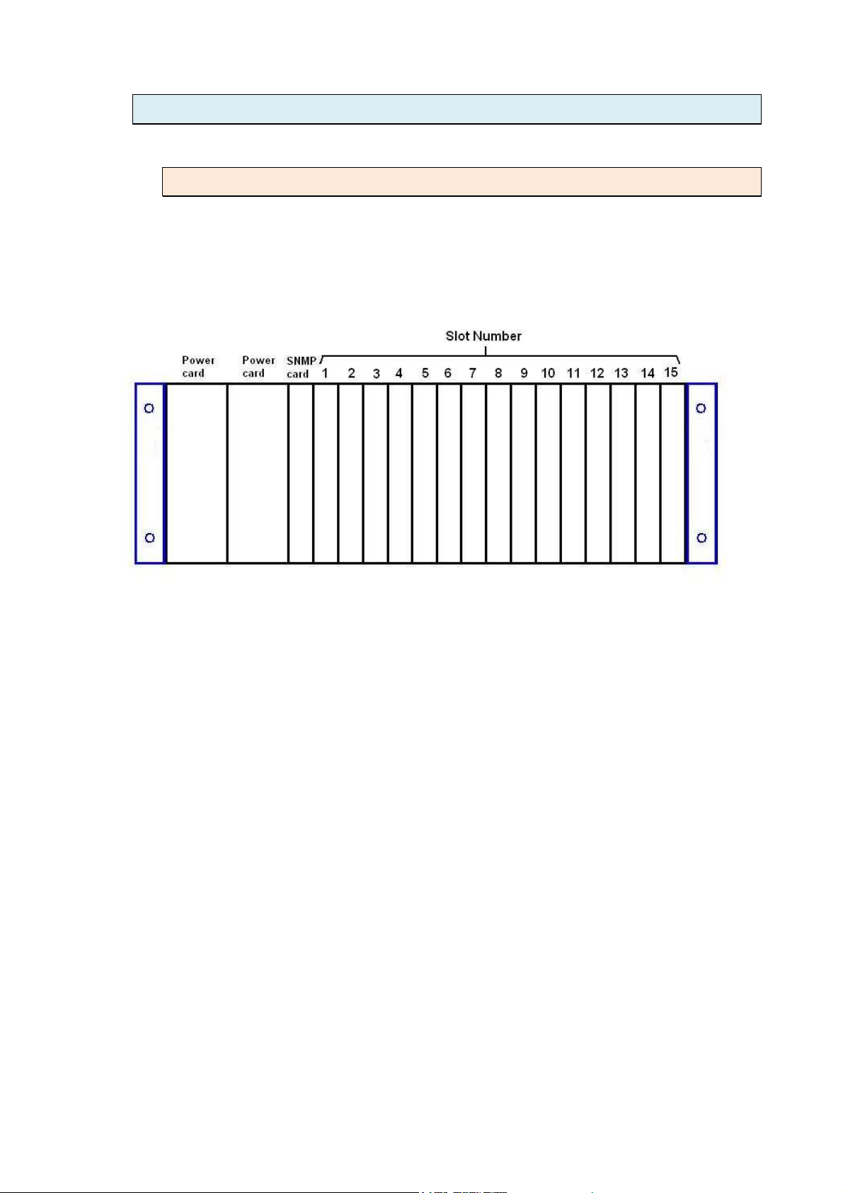
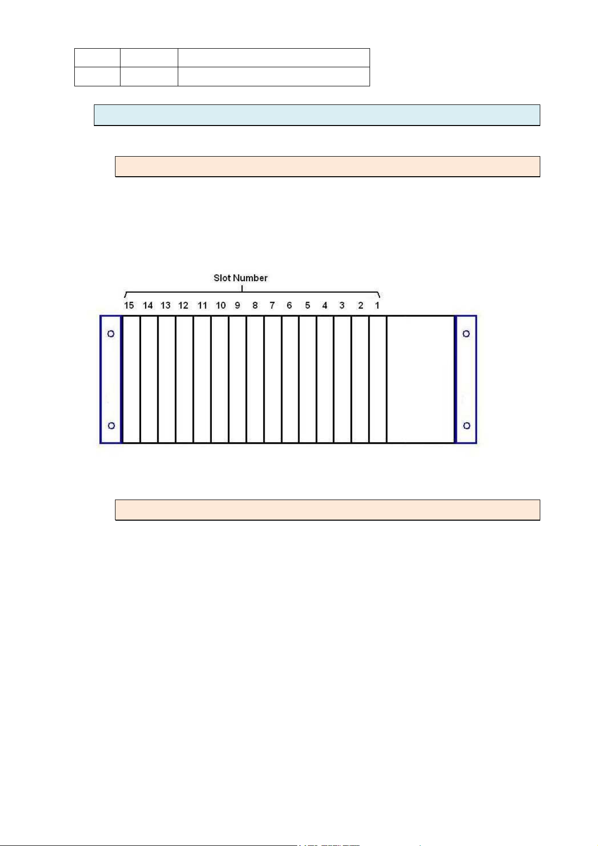
1.4.1 Slot Number
Each slot will have a number from 1 to 15 indicating the slot number location of
the right-top side of each line cards. From the front view of the chassis, the
numbers go from left to right.
13
Page 14
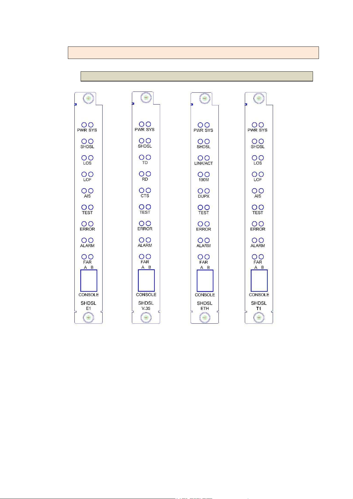
1.4.2 Line card
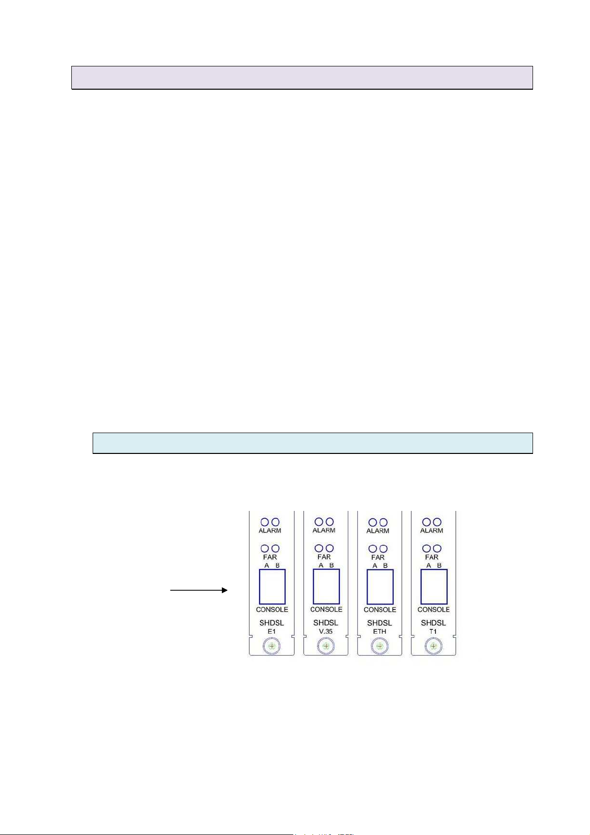
1.4.2.1 View of Front Panel on Line Card
SHRM03bB SHRM03b-V35 SHRM03b-ET100
SHRM03b-T1
E1 interface V.35 interface Ethernet interface T1 interface
14
Page 15
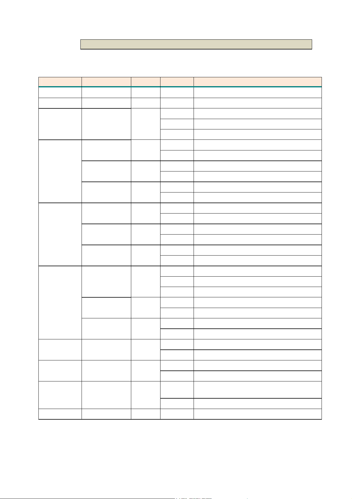
1.4.2.2 LED Indicators
LEDs status of TDM SHDSL.bis Line Card:
Items LEDs Color Active Description
Power PWR Green On Power supply is connected
System SYS Green flash The system is working
On SHDSL.bis line connection is established
SHDSL.bis
Link
SHDSL Green
Blink SHDSL.bis handshake
Off SHDSL.bis line connection is dropped
E1/T1
Interface
status
V.35
Interface
status
Ethernet
Interface
status
LOS Red
LOF Red
AIS Red
TD
RD
CTS
LINK/ACT Green
100M Green
Green
Green
Green
On LOS status is On
Off LOS status is Off
On LOF status is On
Off LOF status is Off
On AIS status is On
Off AIS status is Off
Blink Transmit data in V.35
Off No data transmit in V.35
Blink Received data in V.35
Off No data received in V.35
On CTS signal is On
Off CTS signal is Off
On LAN port connected
Blink Transmit or received data over Ethernet
Off LAN port is disconnected
On LAN port connect with 100M NIC
Off LAN port acts in 100M
DUPX Green
Diagnostic
Status
Error Status ERROR Red
Alarm
Status
FAR Yellow Off No used
TEST Yellow
ALARM Red
On LAN port is Duplex mode
Off LAN port isn’t duplex mode
On System is testing for connection
Off System is working normally
Blink Error second occurs
Off No error second
On
Off No alarm status
15
SHDSL.bis line connection is dropped
E1/T1 connection is dropped
Page 16
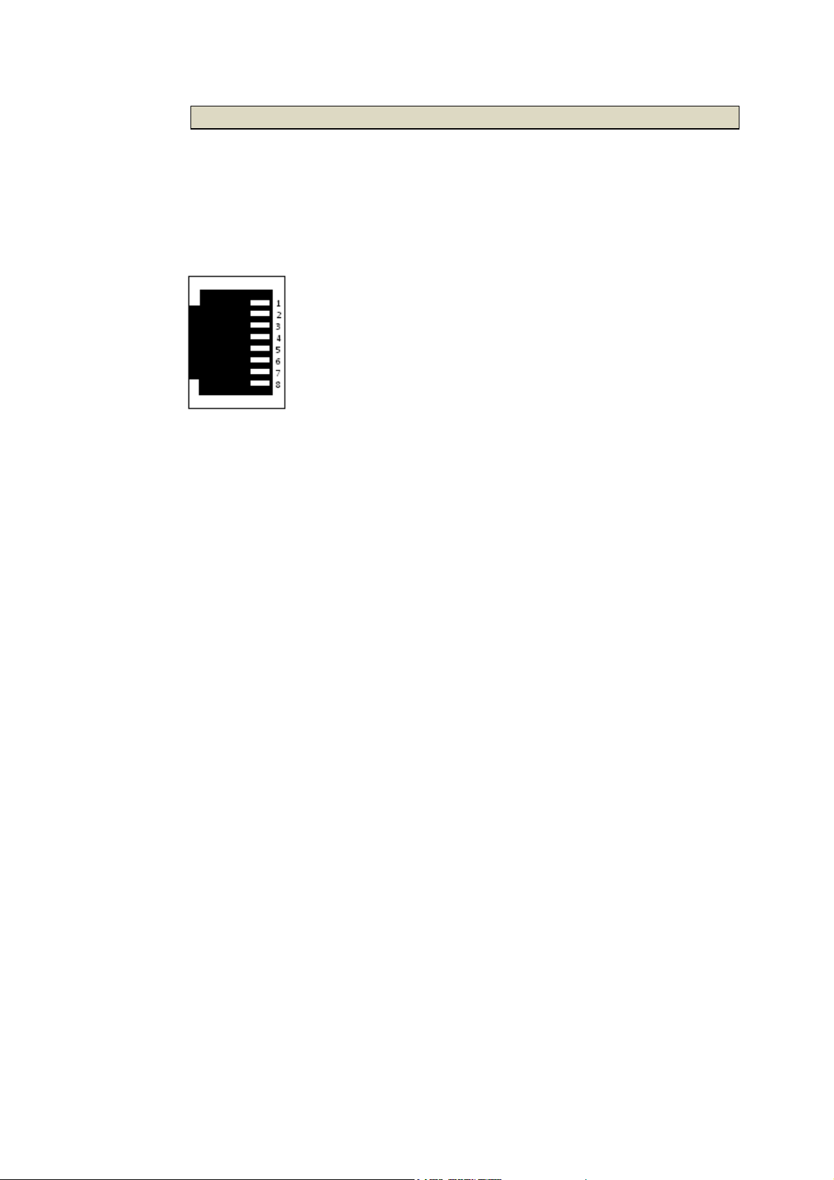
1.4.2.3 Console Connector
The front panel of each line card provides an RJ-45 connector for
configuration, individually from each channel of each line cards. The terminal
settings are 115200, 8 bit, no parity, 1 stop bit and no flow control.
16
Page 17
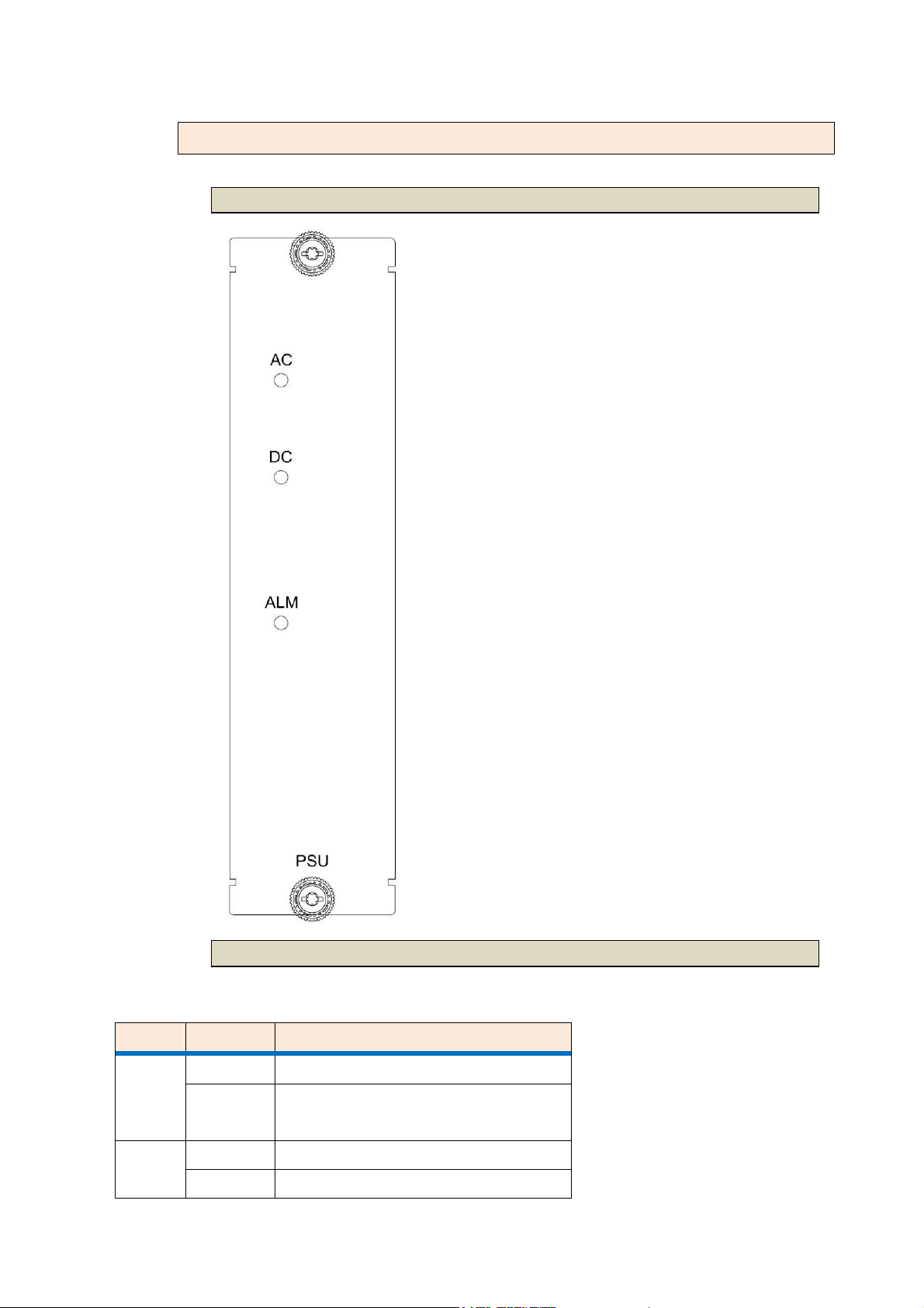
1.4.3 Power Supply Module
1.4.3.1 View of Front Panel on Power Supply Module
1.4.3.2 LED Indicators
LED status of Power Supply Module:
LEDs Active Description
On AC input is be used
AC
AC input isn’t be used or no AC
Off
input
On DC input is be used
DC
Off DC input isn’t be used or no DC
17
Page 18
input
ALM On Power input failure
1.5 Rear Panel
1.5.1 Slot Number
Each slot will have a number from 1 to 15 indicating the slot number location of
the right-top side of rear penal of each line card. From the rear view of the
chassis, the numbers go from right to left.
1.5.2 View of Rear Panel on Line card
The rear panel provides all of the data connections for each line card. A total
of 15 slots are available for SHDSL.bis TDM based Line Card.
The following is a description of all the connectors for the line cards located on
the rear panel.
18
Page 19
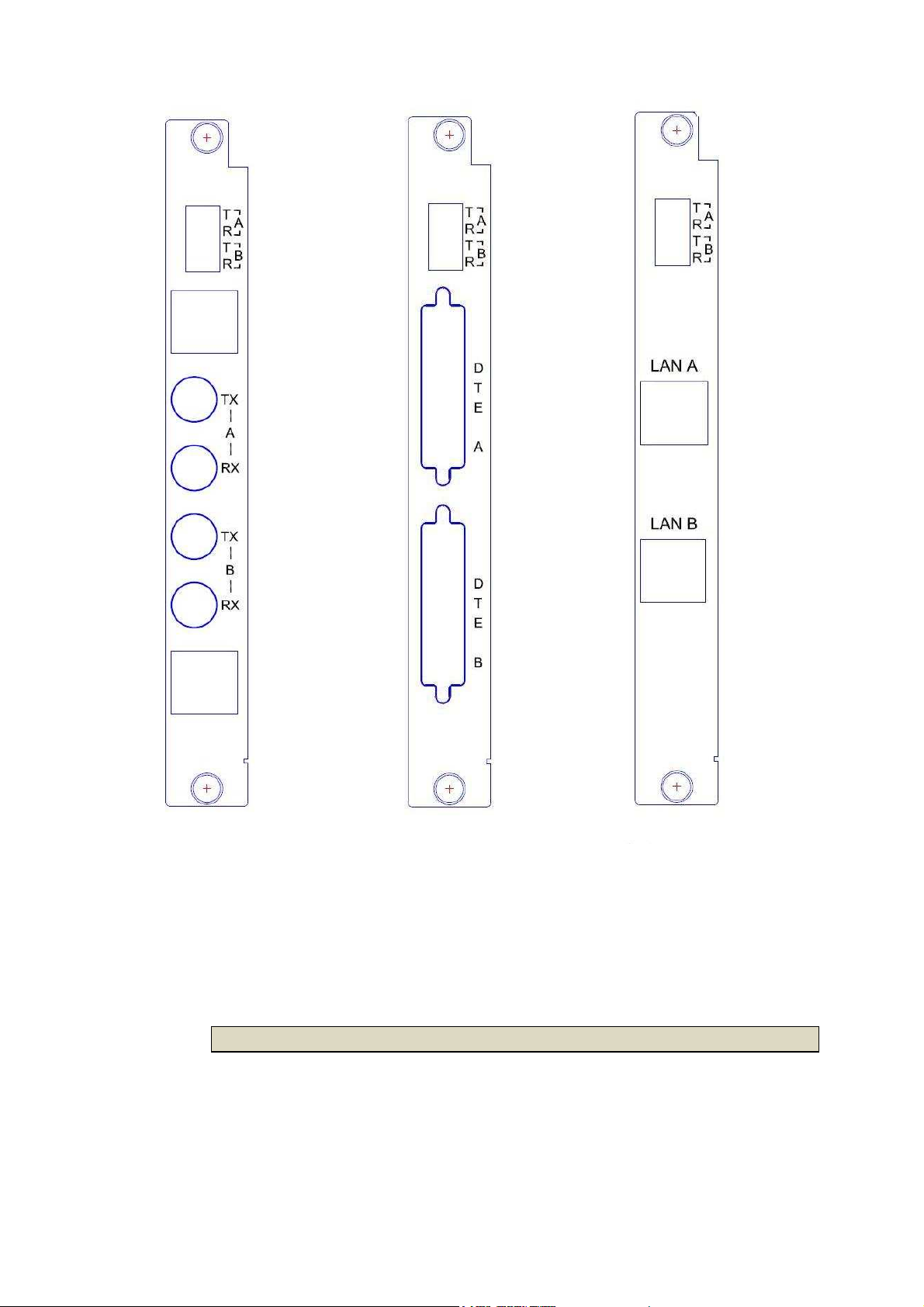
SHRM03b E1 Interface
SHRM03b-T1 T1 Interface
.
SHRM03b-V35 V.35
Interface
SHRM03b-ET100 Ethernet
Interface
1.5.2.1 DSL connector
Use 4 pins wire wrap pin header provided the DSL twisted pair wire connect to
the remote CPE device.
19
Page 20
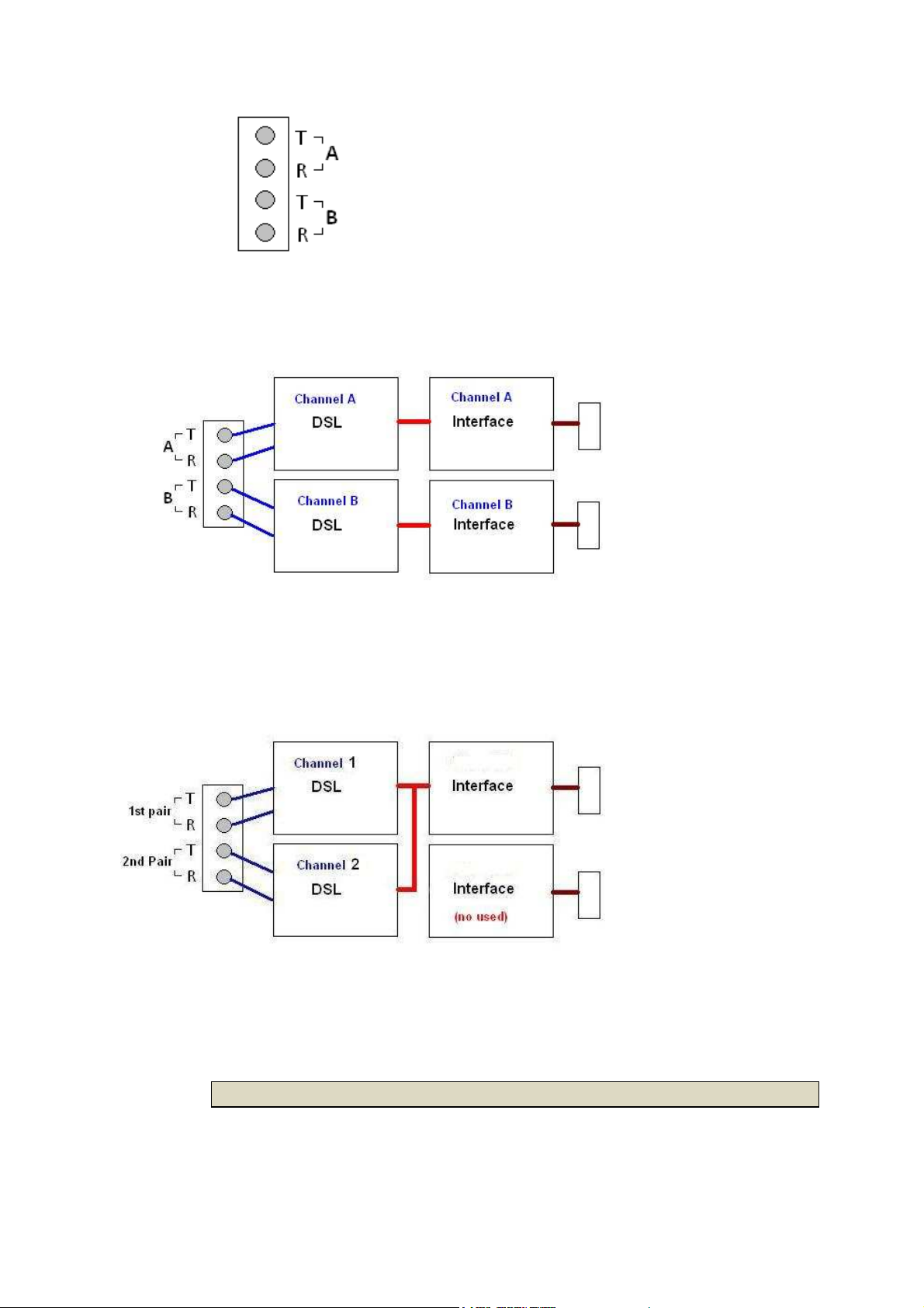
2-wire mode ( 2 channel per card)
When using 2-wires(One pair) mode, there are two pins labeled T (Tip) and R
(Ring) on channel A and channel B.
4-wire mode (1 channel per card)
When using 4-wires(Two pair) mode, the label A and B means 1st pair and 2nd
pair of DSL wiring.
1.5.2.2 E1 Interface Connector
User can using one of the connector type of the following.
20
Page 21
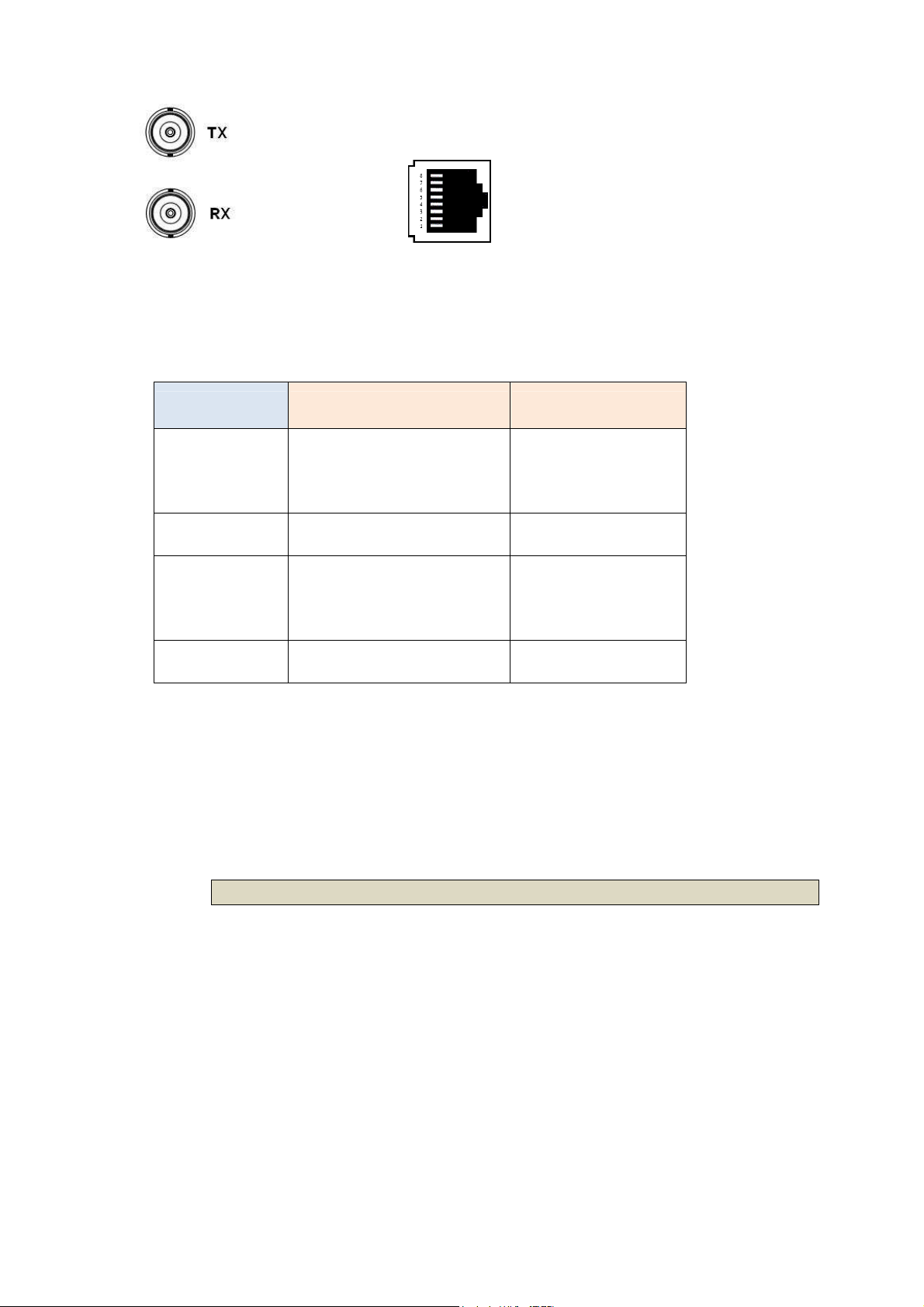
75 Ohms 120 Ohms
BNC Connector RJ-48C Connector
The internal wiring between BNC sockets and RJ-48C:
Signal Name
Transmit Tip Center pin of Tx
BNC Connecters RJ-48C Connector
5
Connector
Transmit Ring Shield of Tx Connector 4
Receive Tip Center pin of Rx
2
Connector
Receive Ring Shield of Rx Connector 1
It is support dual jacks of BNC (75 ohms) and RJ-45(120 ohms).
When using 4-wire(2 pairs) mode, only the upper side of E1/T1 connector can
be used.
1.5.2.3 Serial Interface connector
21
Page 22
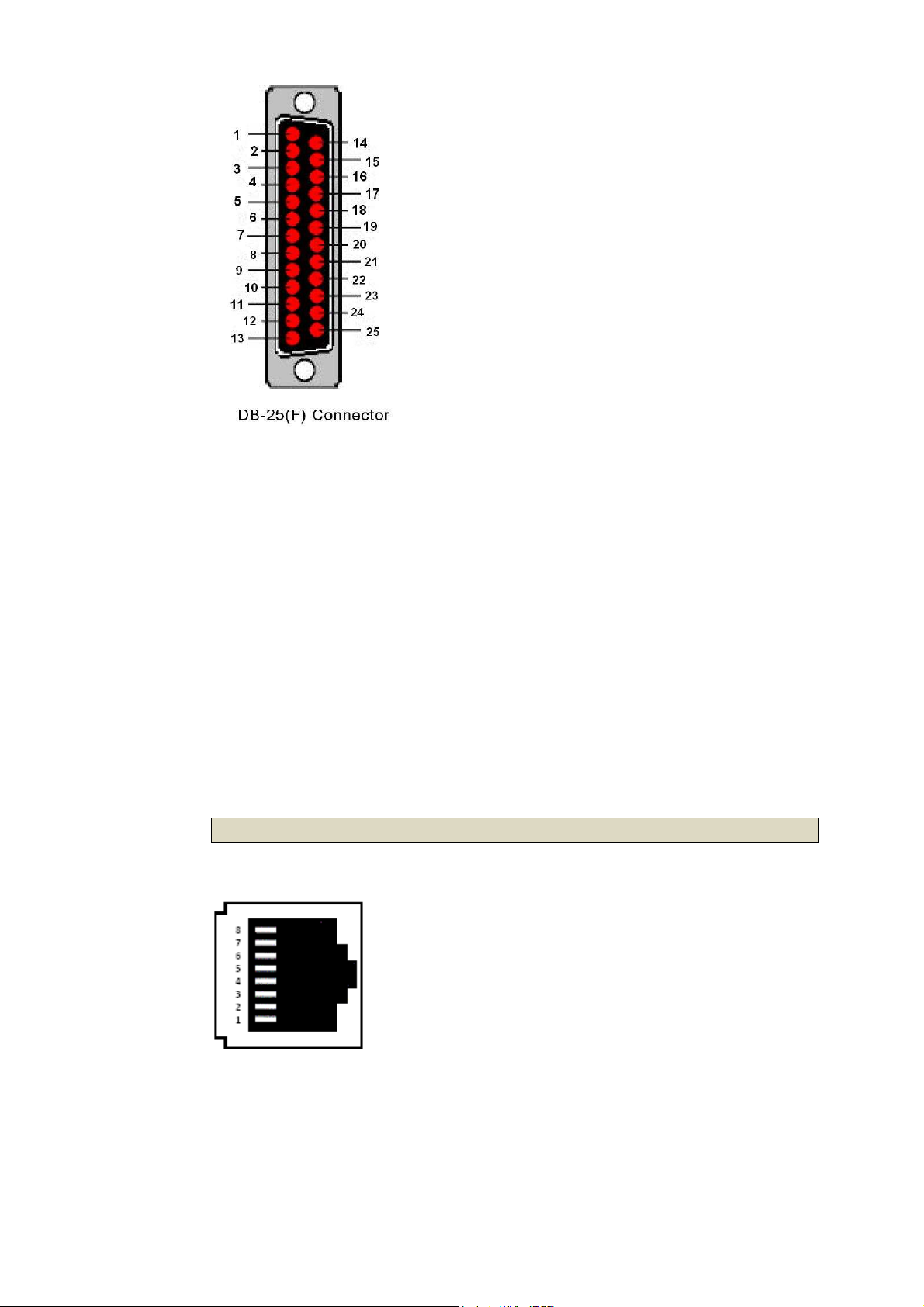
On the rear panel of serial Interface Line card, there have two DB-25 female
connectors provides serial interface connections for channel A (on upper side)
and channel B (on below side).
When using 4-wire(2 pairs) mode, only the upper side of DB-25(F) connector
can be used.
If the DTE (Data Terminal Equipment) connector is using 34-pin Winchester type,
we must use the cable adaptor from DB-25 to Winchester (M.34).
If there is X.21 application, we must use the DB-25 to DB-15 adaptor cable.
When using 4-wire(2 pairs) mode, only the upper side of DB-25(F) connector
can be used.
1.5.2.4 Ethernet Interface connector:
On the rear panel of Ethernet Interface Line card, there have two RJ-45
connectors provides standard Ethernet connections for channel A (on upper
side) and channel B (on below side).
22
Page 23

When using 4-wire(2 pairs) mode, only the upper side of RJ-45 connector can
be used.
23
Page 24
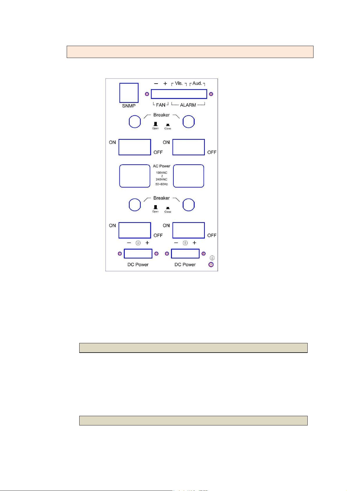
1.5.3 View of Rear Panel on Power Supply Module
SNMP Ethernet jack FAN DC
power output connector
ALARM device connector
Fuse (Breaker)
Power Switch
(AC input)
Power receptacle
Fuse (Breaker)
Power Switch
(DC input)
DC input
Connector Frame grounding screw
The power modules can be using on AC or DC operation, as the chassis
backplane is designed for -48VDC direct connection to central office power.
1.5.3.1 Power receptacle
This is an IEC Connector. To connect the AC power to the chassis, insert the
female end of power card to the power receptacle on the rear panel.
Connect the other end of the supplied power card to a 100~240V AC power
outlet.
There have two power switches which control for AC and DC power input.
1.5.3.2 Power Switch
24
Page 25
1.5.3.3 Breaker
The circuit breakers provide over current protection for AC or DC inputs. They
are resettable by pushing back to the closed position.
1.5.3.4 Terminal Block connector
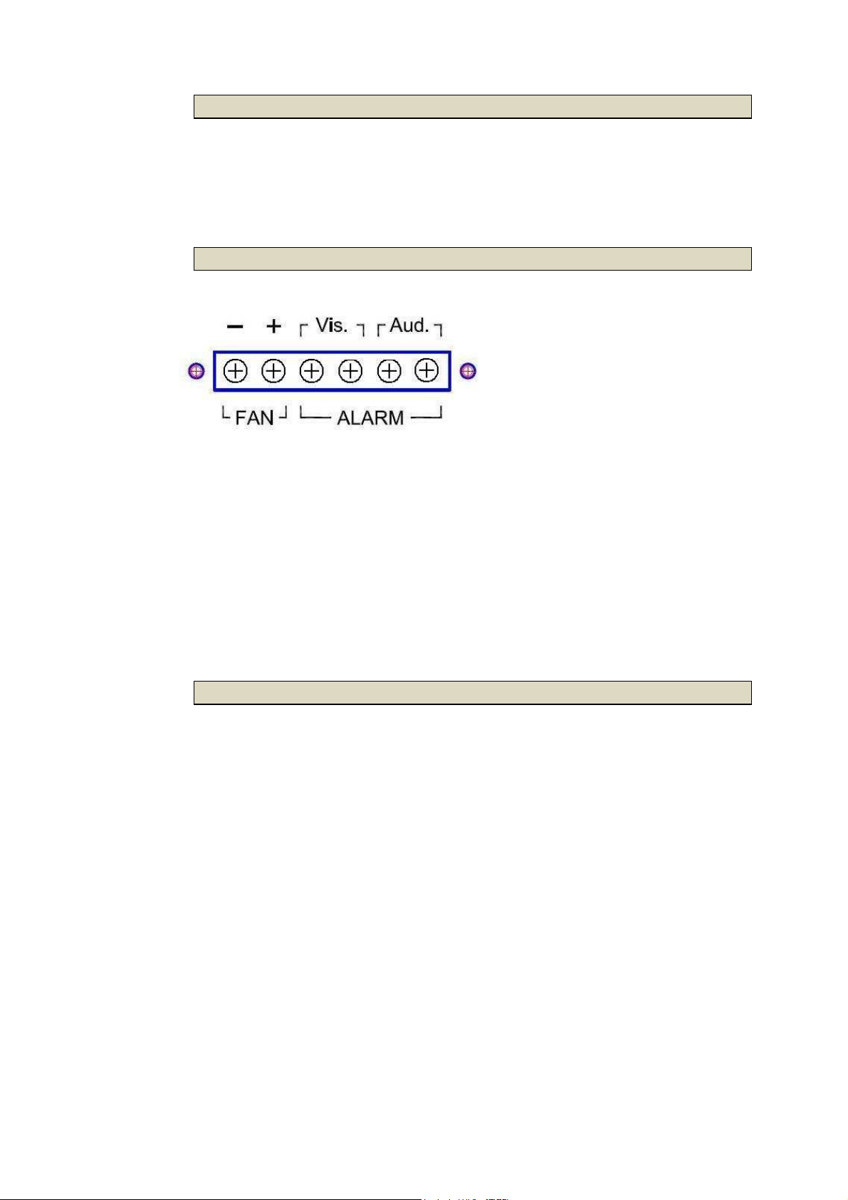
There have two alarm connectors (Vis. Alarm and Aud. Alarm) for TDM based
line card.
The DC output terminal strip provides hard wired connections for DC power
(-48VDC) to
the FAN modules.
The size of the screws in the terminal block is M3.0.
1.5.3.5 DC Power input connector
This terminal strip provides hard wired connections for DC power (48VDC) to
the power service input.
WARNING!:
Proper polarity must be observed for DC power connections or severe
electrical damage may occur to the chassis. Always confirm the polarity with
a voltage meter before inserting line cards or powering on the mains switches.
25
Page 26
2 Installation
2.1 General
The Installation chapter will cover the physical installation of the SHRM03b
series, the electrical connections, line card installation and cabling
requirements. A brief overview of the functional components such as power
modules, line cards and management options will also be outlined in this
chapter.
Required Tools
You will need these tools to install the SHRM03b series Rack Mount:
• Phillips screw driver for chassis installation screws.
• Wrist strap or other personal grounding device to prevent ESD occurrences.
• Antistatic mat or antistatic foam to set the equipment on.
2.2 Unpacking
Step 1. Inspect the outside carton for any shipping damage and report
immediately to your freight forwarder if any damage is visible.
Step 2. Place the shipping carton with the top facing up. Carefully cut through
the shipping tape with a box cutter knife.
Step 3. Open the top cover of the carton and remove any pizza box.
Step 4. Pull the entire chassis straight up out of the carton
Step 5. The chassis should be wrapped in a plastic bag. Remove the chassis
from the plastic bag. Set the chassis on a secure flat surface and again inspect
for any shipping damage. Report any damage immediately to your freight
forwarder.
2.3 Installation with Rack
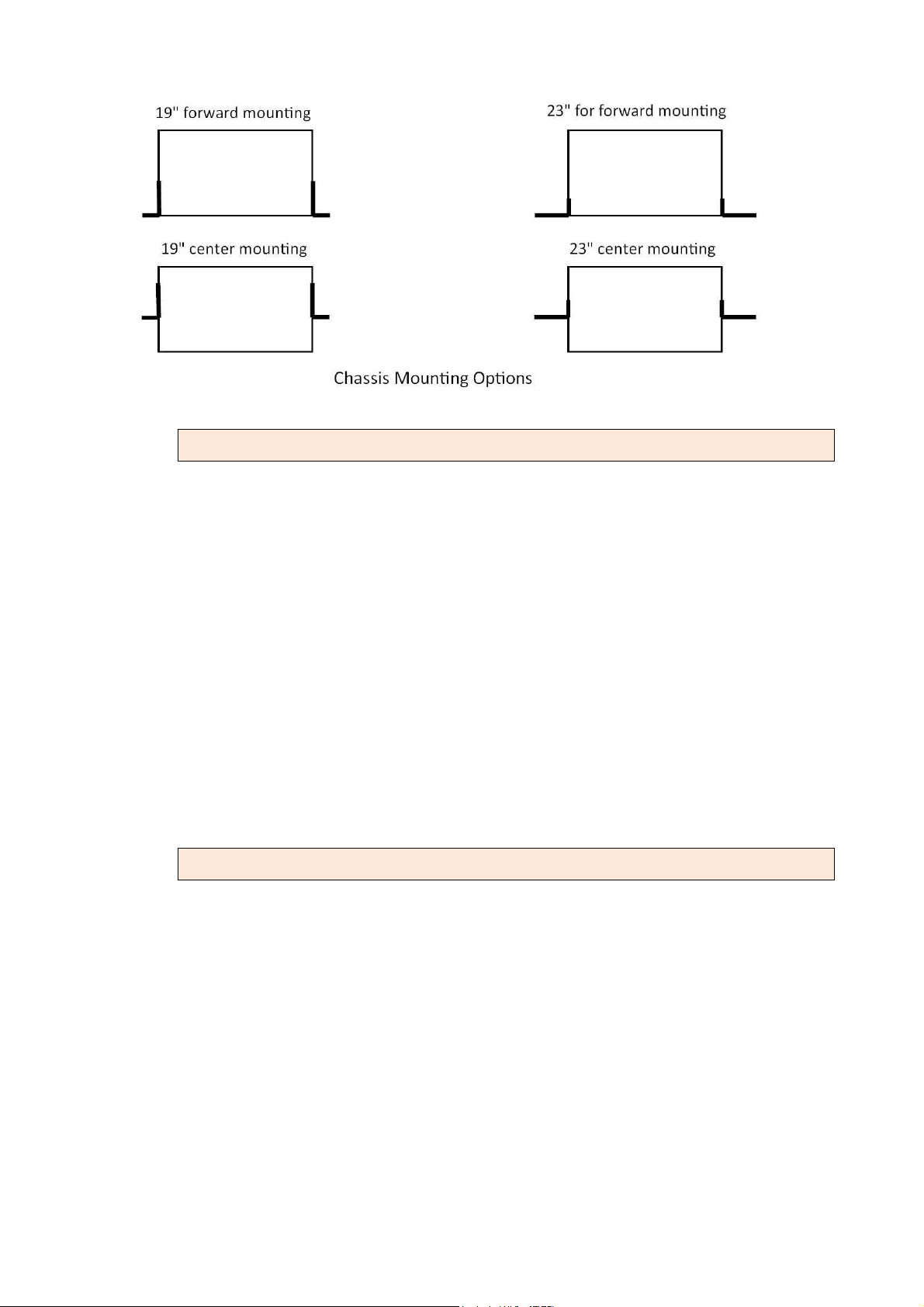
The rack mount brackets that ship with the SHRM03b series chassis allow
mounting in either 19" or 23" wide rack spaces. A total of four different
mounting configurations are possible. Please see the chassis top view graphics
below.
26
Page 27
2.3.1 Attaching the Mounting Brackets
Step 1. Place the supplied rack- mounting bracket on one side of chassis
ensuring the mounting holes on the chassis line up to the mounting holes
on the rack mounting bracket.
Step 2. Insert the supplied screws (M3X4 flat head screws) into the rack
mounting holes and tighten with a screwdriver.
Precautions: Only M3X4 flat head screws can be used, failure to use the
proper screws may damage the unit.
Step 3. Repeat the process for the rack-mounting bracket on the other side of
the chassis.
Step 4. You may now mount the chassis on a rack. Proceed to the next
section.
2.3.2 Mounting the chassis on a Rack
Precautions:
(a) Make sure the rack will safely support the combined weight of all the
equipment it contains.
(b) Make sure the position of the chassis doesn’t make the rack unstable or
top-heavy. Take all necessary precautions to anchor the rack securely
before installing the unit.
(c) For proper ventilation, ensure the air flow around the front, sides, and back
of the chassis is not restricted.
Do not install the chassis in an environment where the operation ambient
(d)
27
Page 28
temperature might exceed 45˚C.
Step 1. Insert the chassis into the 19-inch or 23-inch rack ensuring the
rack-mounting holes on the chassis line up to the mounting hole on the rack.
Step 2. Secure the chassis to the rack with the supplied rack screws. Fasten the
lower pair of screws before the upper pair of screws. This ensures that the
weight of the unit is evenly distributed during installation. Ensure that the
ventilation holes are not obstructed.
It is recommended that the SHRM03b chassis be mounted into the rack
cabinet prior to installing any required power modules and line cards. Without
cards, the chassis is light weight and can easily be installed by a single person.
WARNING: A fully loaded chassis can be quite heavy and unbalanced.
Dropping a fully loaded chassis would result in severe damage to the chassis
and line cards, as well has pose a serious safety hazard resulting in bodily injury
to the installation personnel. Only trained and qualified personnel should be
allowed to install, replace, or service this equipment.
2.3.3 AC power Connection
To connect the AC power supply is perform the following:
1. Using the supplied standard power cable with safety grounding connector,
connect the power cable to the AC main socket located on the back
panel.
2. Connect the power cable to a grounded AC outlet.
3. Confirm that the device is connected and operating by checking that the
Power Supply LED(AC) on the front panel is green.
The chassis can use dual power supply modules for redundant power system
2.3.4 DC Power Connection
To connect the DC power supply is perform the following:
1. Remove the plastic cover on the terminal block.
2. Loosen the two screws marked “-48V” and ”PWR GND”, so that you can
slide the DC cable beneath it. Insert the DC cable into the connector first,
and screw it down tight.
28
Page 29
3. Connect the power cable to the DC power supply.
4. Confirm that the chassis is connected and operating by checking that the
Power Supply LED(DC) on the front panel is green.
WARNING: Before connect the DC power cable to the input terminal block
of rear panel, ensure that the power switch in the “OFF” position and the DC
power is OFF.
NOTE: A qualified electrician must perform all connections to DC power and
to safety grounds. All electrical wiring must comply with applicable local or
national codes and practices.
2.4 Line Card Removal / Replacement
This section will explain how to install and remove SHDSL.bis Line Cards.
2.4.1 Installing a Line Card
Use the following procedure to install a SHDSL.bis Line Card in the main chassis.
Step 1. Using either an anti-static grounded wrist strap or touching a grounded
metal frame, remove the line card from its anti-static protective bag by
grasping the metal panel. Do not touch the PCB or components on the PCB.
Step 2. While still grasping the center of the front panel of the card with one
hand, place the other hand under the card to support it.
Step 3. Slide the Line Card into the slot until it makes contact with the
backplane.
Step 4. Gently press the card the remaining way into the backplane
connector until fully seated.
Step 5. Tighten the two thumbscrews by hand.
2.4.2 Removing a Line Card
Use the following procedure to remove a SHDSL.bis Line Card from the main
chassis.
Step 1. Using either an anti-static ground wrist strap or by touching a grounded
metal frame, loosen the two thumbscrews, using a flat blade screwdriver if
necessary. Do not remove the screws completely.
29
Page 30

Step 2. Grasp the line card by the captive thumbscrews and pull evenly on
both to release the backplane connectors.
Step 3. After you have the card partially out of the chassis, place one hand
under the card to support it.
Step 4. Slide the card completely out of the slot and place in an anti-static
protective bag.
30
Page 31
3 Operation
This chapter will deal with the specifics of configuration and operation of all
aspects of the SHRM03bB Line card series (including SHRM03bB, SHRM03b-V35,
SHRM03b-ET100 and SHRM03b-T1)from individual line card configuration,
management options and typical application examples and settings.
Configuration and operation of this product via console port with terminal
emulation program. The configuration of the TDM base SHDSL.bis Line cards is
performed via a menu-driven embedded software, using a standard ASCII
terminal or a PC running a terminal emulation application connected to the
front panel CONSOLE port.
Windows includes a terminal emulation program called HyperTerminal.
Connect the appropriated communication port from the PC to this device.
After the physical connection is made, you are ready to configure this product.
Make sure you have connected the supplied RS-232C serial cable (DB9F to
RJ-45 Plug) to the console port on the rear panel of this product.
3.1 Login Procedure
Check the connectivity of the RS-232 cable from your computer to the serial
port of line card.
Console cable
Run the terminal emulation program such as Hyper Terminal with the following
setting:
Emulation: VT-100 compatible
Band rate: 115200, Data bits: 8, Parity: None, Stop Bits: 1, Flow Control: None
31
Page 32
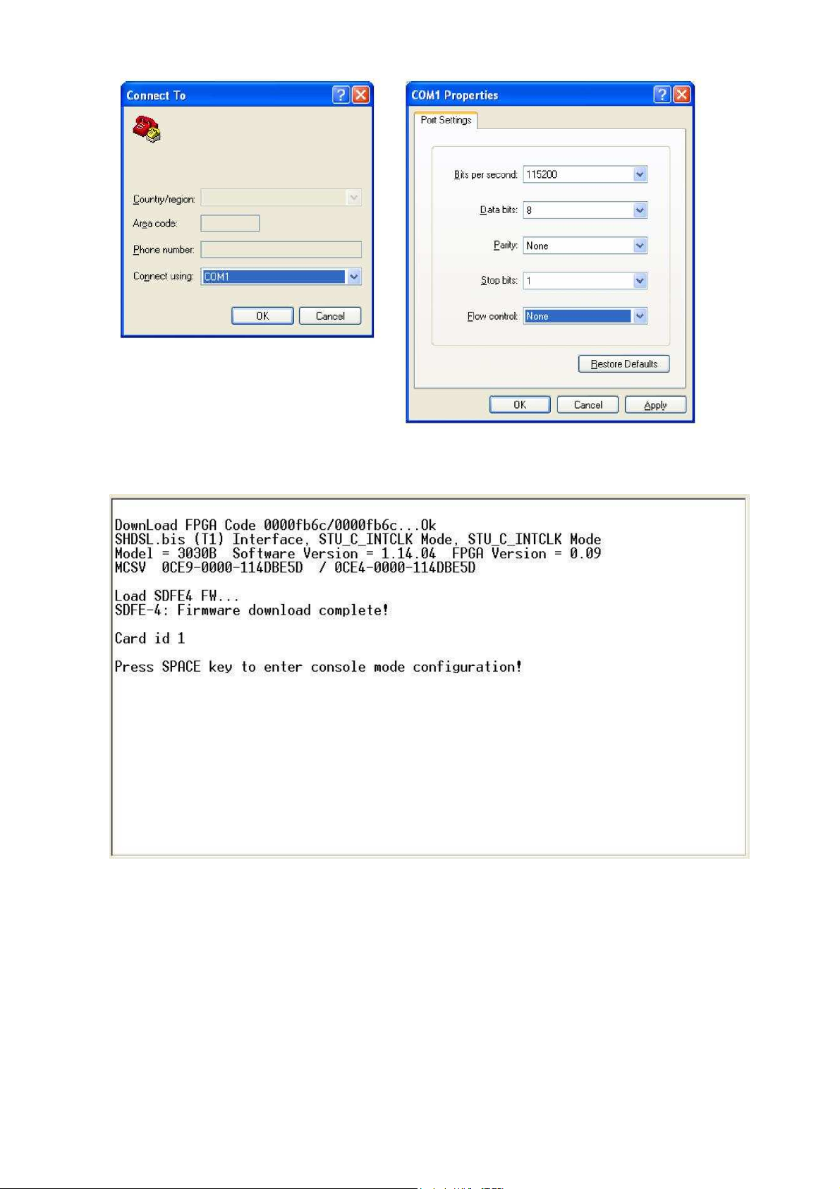
At the start up screen, you will see:
“Card id” is showed what slot number’s line card on your connection. The card
IDs are from 1 to 15.
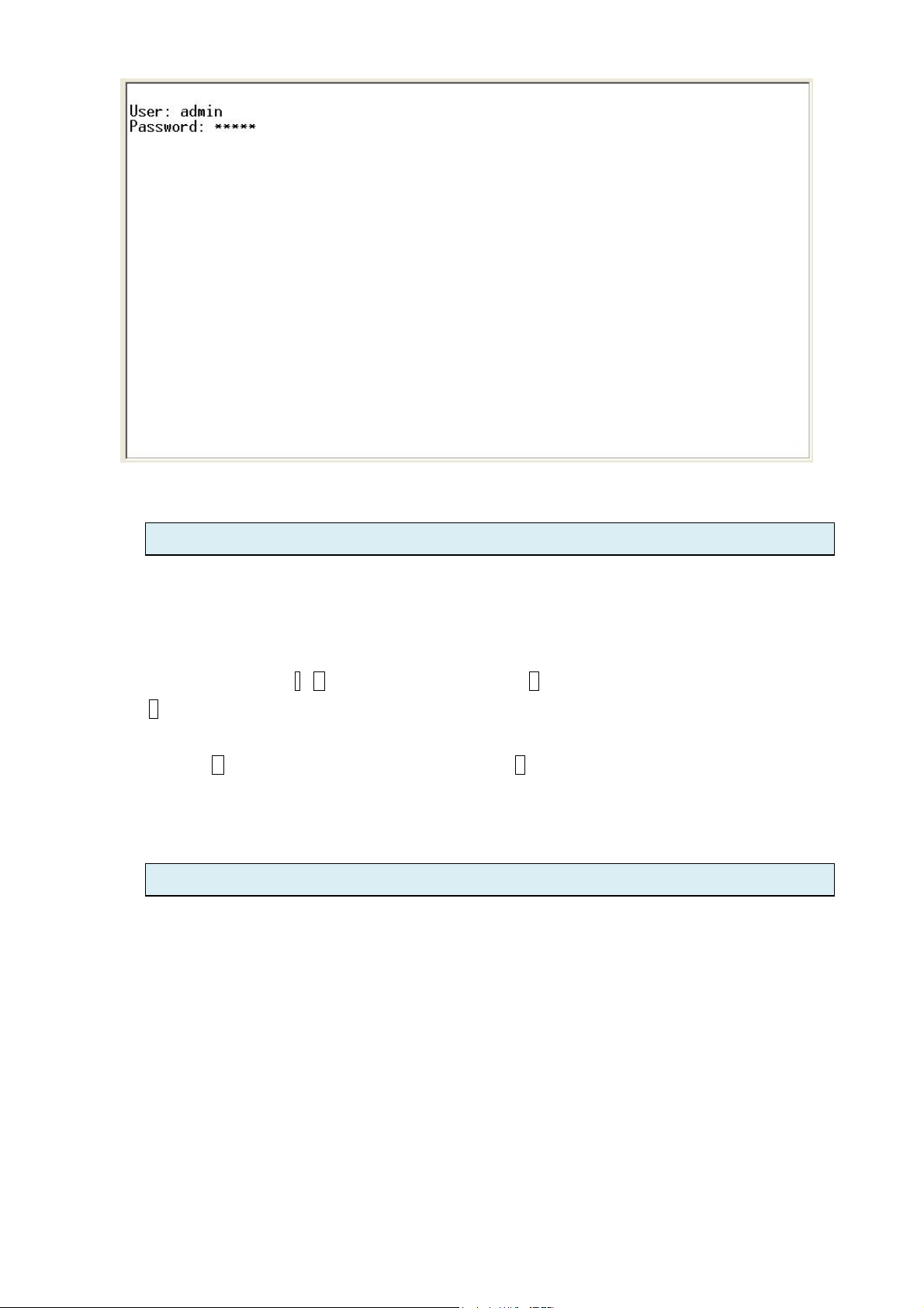
Press the SPACE key when the first screen appears, it can enter to login screen.
When you see the login screen, you can logon to device.
Username use “admin”. When the system prompts you for a password, type
“admin” to enter is O.K.
32
Page 33
3.2 Operation interface
On serial console, the line cards implement menu driven interface. The menu driven interface is a
user-friendly interface to general operations.
The following figure gives you an example of the menu driven interface. In the menu, you scroll
up/down by pressing key I / K, select one command by key L, and go back to a higher level of menu by
key J.
For example, to show the system information, just logon to the line card, move down the cursor by
pressing key K twice and select “show” command by key L, you shall see a submenu and select
“system” command in this submenu, then the system will show you the general information.
3.3 Window structure
33
Page 34

From top to bottom, the window is divided into four parts:
1. Product name: “SHDSL.BIS LINE CARD”
2. Menu field: Menu tree prompts on this field. Symbol “>>” indicates the cursor place.
3. Configuring field: You will configure the parameters in this field. < parameters > indicates the
parameters you can choose and < more…> indicates that there have submenu in the title.
4. Operational key-in command list for your reference.
34
Page 35

3.4 Menu Driven Interface Commands
Before changing the configuration, familiarize yourself with the operations list in the following table. The
operation list will be shown on the bottom field of the window.
Menu Driven Interface Commands
Keystroke Description
[UP] or I Move to above field in the same level menu.
[DOWN] or K
U
O
[LEFT] or J Move back to previous menu
[RIGHT] or L Move forward to submenu
[ENTER] Move forward to submenu
[TAB] To choose another parameters
Ctrl + C To quit the configuring item
Move to below field in the same level menu.
Move to top field in the same level menu
Move to bottom field in the same level menu
After you have some necessary setting for line card, if may show “Message:
Done, Reboot needed”. You must make sure to write the new configuration to
NVRAM by “reboot” command and then reboot the system. Otherwise, all of
your changes will not take effect.
If it doesn’t show everything when you have set up some configuration items, it
means that it take effect automatic. You needn’t take the “reboot” operation.
35
Page 36

Use this menu to show general information, all configurations
3.5 Main menu
The main menu is as following:
The main menu is prompted as following:
Menu Title Function
Use this menu to setup SHDSL type, SHDSL parameters and
Setup
E1/V.35/Ethernet /T1 parameters or restore factory default
setting.
Status
Use this menu to show SHDSL status, E1/V.35/Ethernet/T1
status and statistics or clear the statistics
Show
and all configurations in command script.
Reboot
Diag
Upgrade
Use this menu to reset and reboot the system
Use this menu to setup diagnostic utility
Use this menu to upgrade the firmware (kernel and FPGA
code)
Exit
Use this menu to exit
36
Page 37
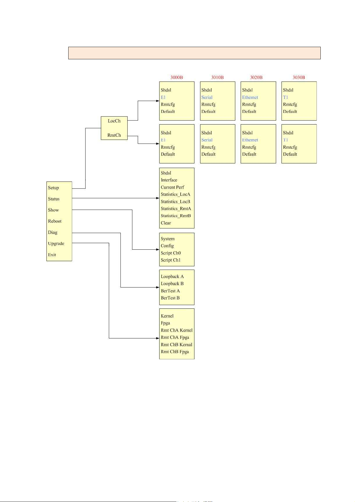
3.5.1 Menu Tree diagram - 2 wire mode
37
Page 38
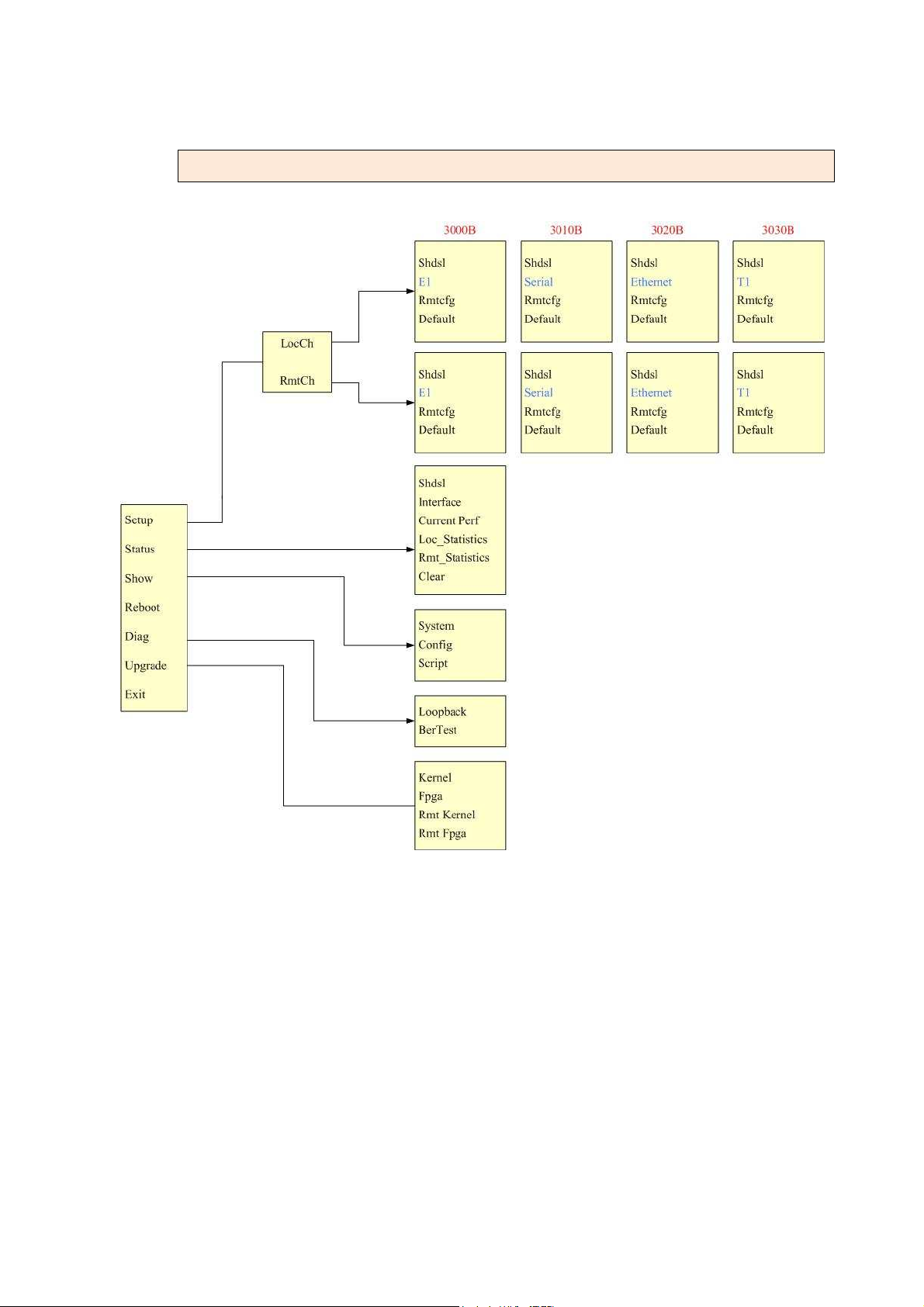
3.5.2 Menu Tree diagram - 4 wire mode
38
Page 39
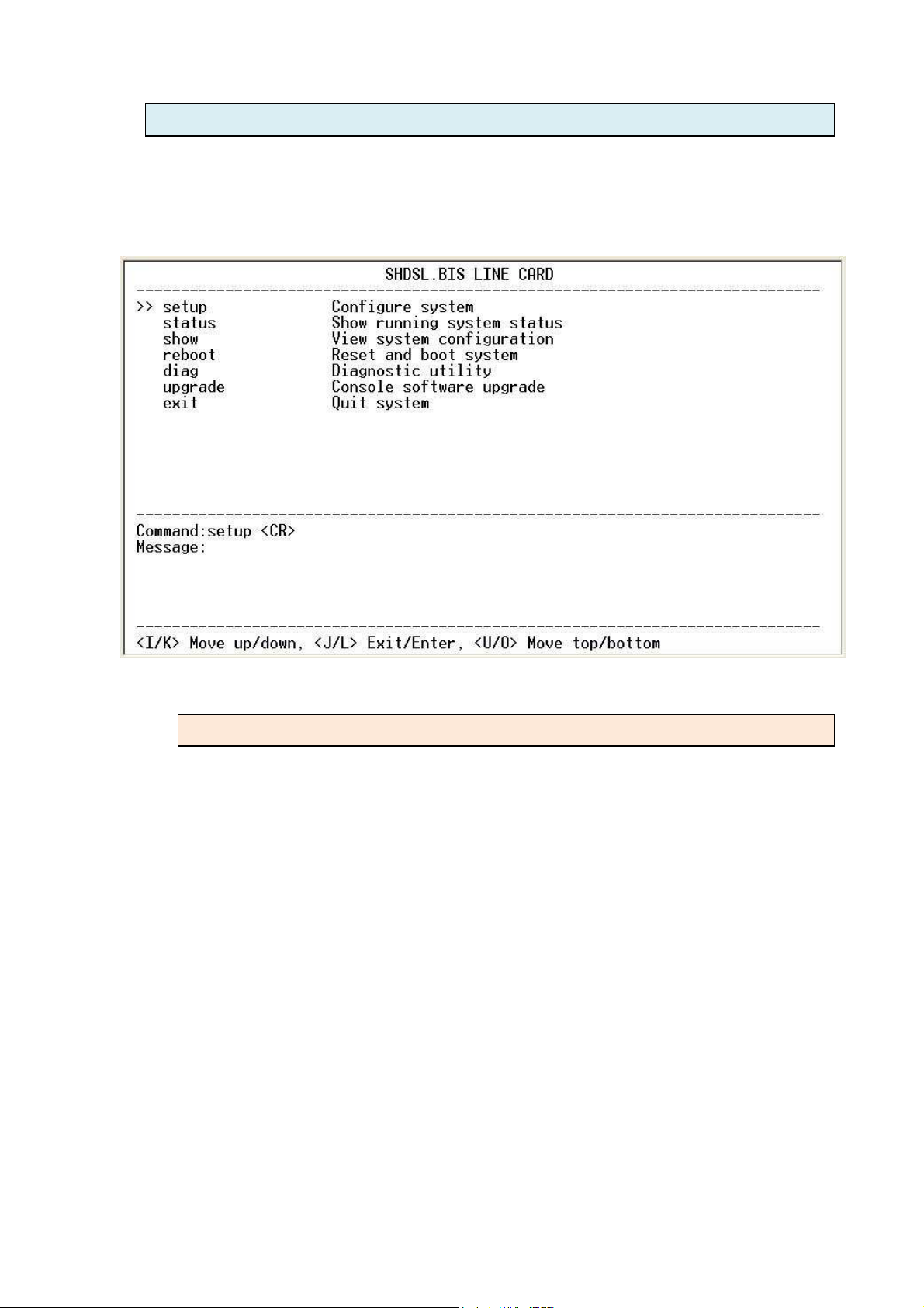
3.6 Setup
From the main configuration menu, we can enter the setup sub menu by
placing the cursor on the setup menu item and pressing the right arrow key or
the ENTER key.
3.6.1 Setup Local
For 1 pair (2-wire) mode:
When using 2-wires (one pair) configuration, the line card has two separate
channels, A and B.
39
Page 40
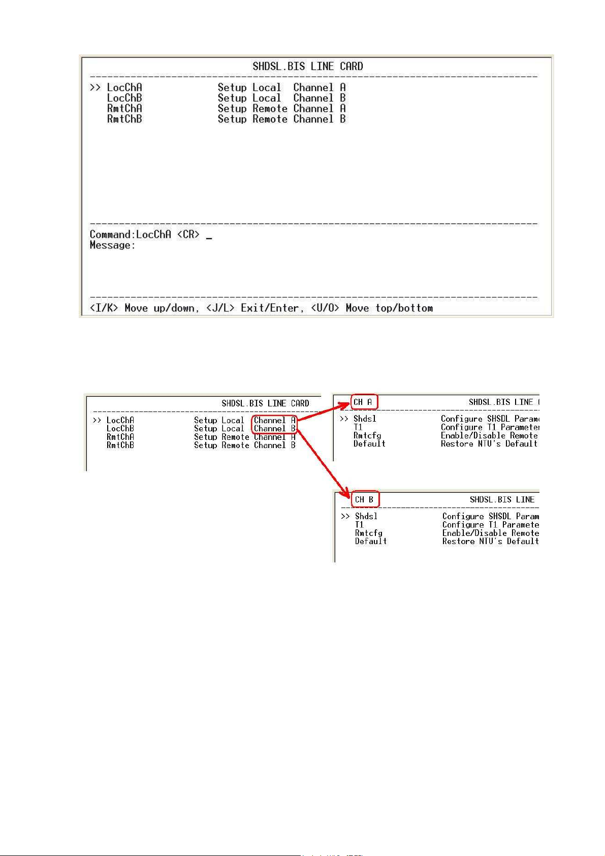
When enter the channel A or B, you can view the left-top side shows CH A or
CH B.
For 2 pair (4-wire) mode:
When using 4-wires (two pair) configuration, the line card has only one
channel.
40
Page 41
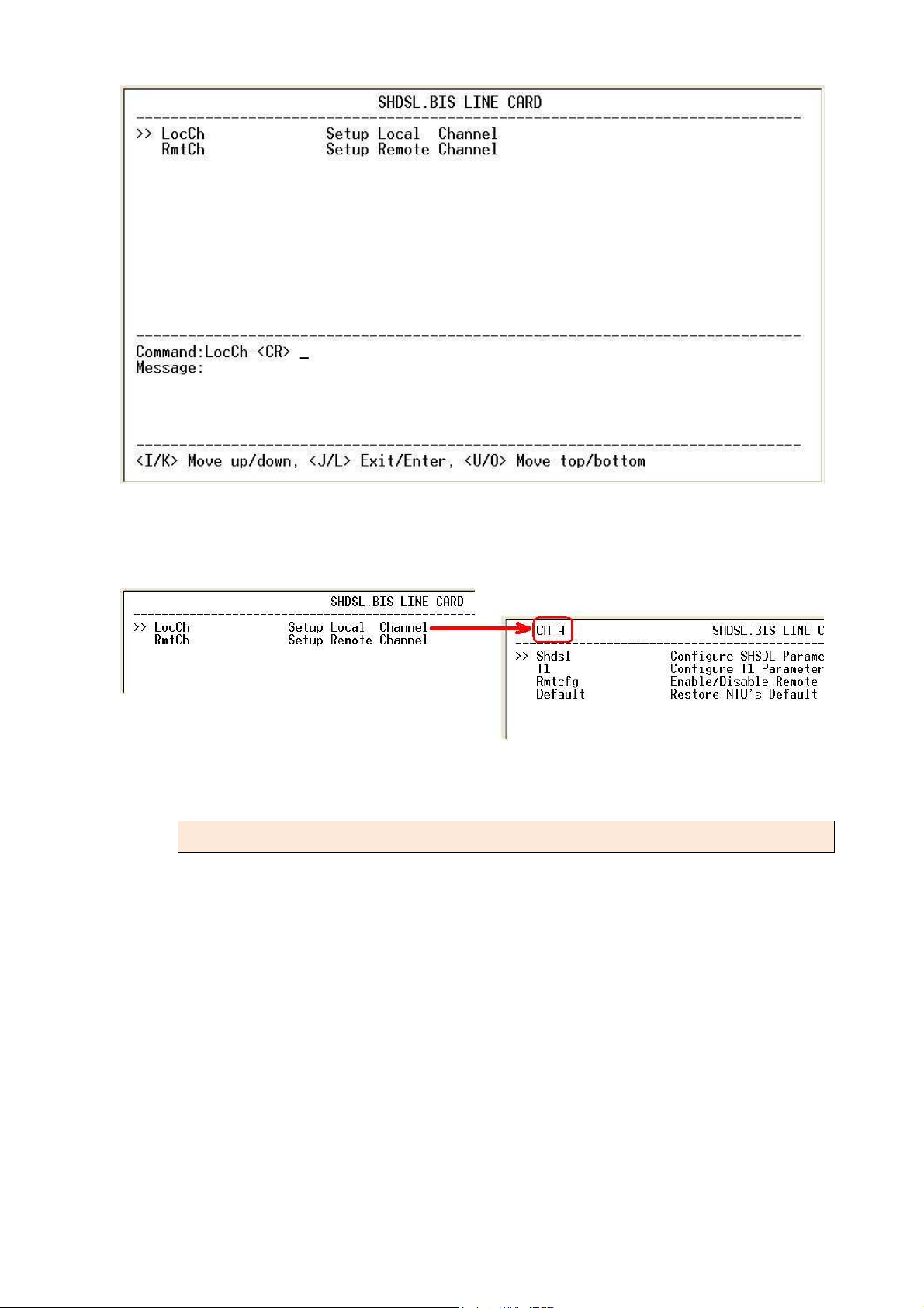
Because there are only one channel, you can only view the left-top side shows
CH A.
3.6.2 Setup Remote
If the Line card has connected to remote side, it can make a setup remote operation. Following diagram
show SHRM03b-V35 Serial interface Line card connect to two 5010B Serial interface NTU. The line
card use 2-wire mode.
41
Page 42
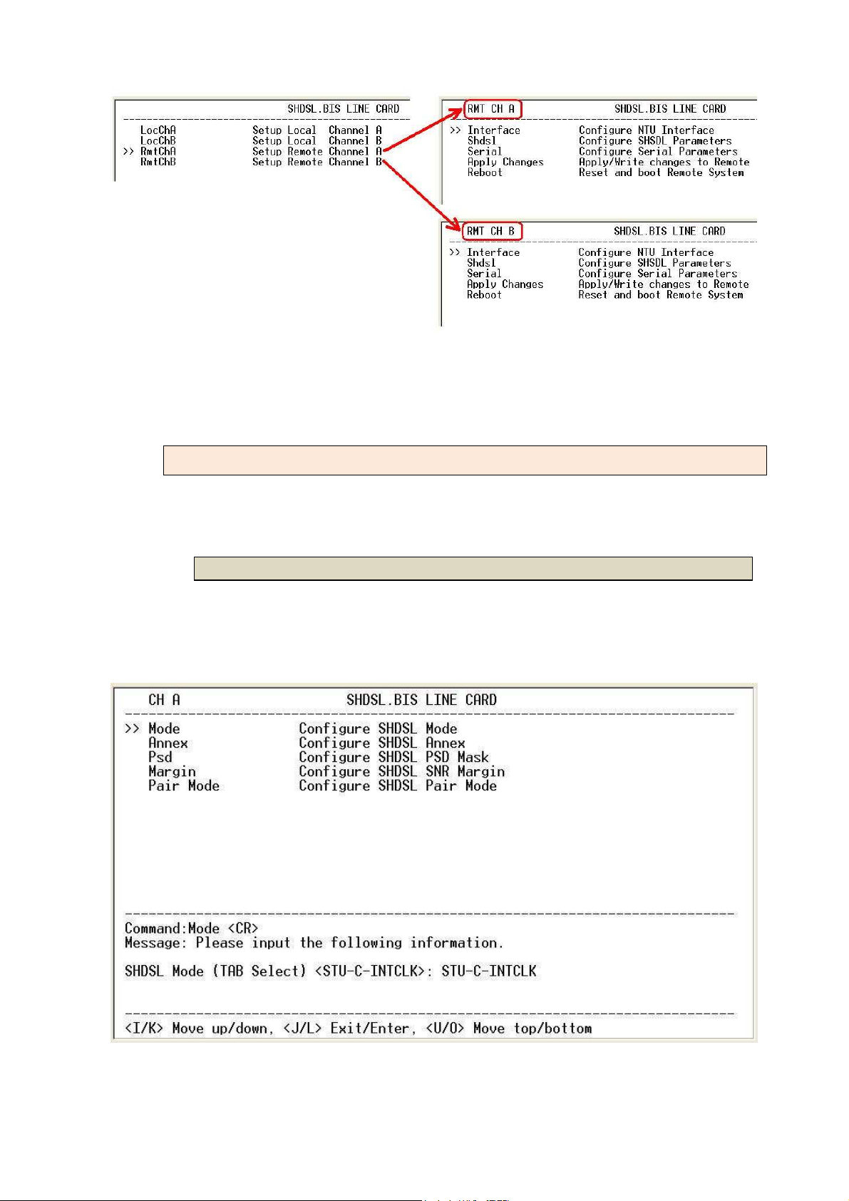
When enter the remote channel A or B, you can view the left-top side shows
RMT CH A or RMT CH B.
3.6.3 Shdsl
The SHDSL setting including Mode, Annex, Psd, Margin and Pair mode.
3.6.3.1 Mode
The mode of SHDSL.bis refers to the clock and the clock setting of the line card.
The settings for the line card are for either internal clock (STU-C-INTCLK) or
recovery clock (STU-C-EXTCLK).
STU-C-INTCLK : Where the clock source is set to internal
42
Page 43

STU-C-EXTCLK : Where the clock source is set to external
[ E1 interface line card] SHRM03b-E1
When connecting this equipment to G.703 E1 transmission equipment, the
normal clock setting should be to take the E1 network timing. In this case the
correct setting for this line card should be STU-C-EXTCLK.
[Serial interface line card] SHRM03b-V35
Unless the connected data communications equipment is acting as a DCE
and provides clock to the ETC pin, the correct setting for this line card should
be STU-C-INTCLK.
[Ethernet interface line card] SHRM03b-ET100
Since Ethernet does not provide a clock, the correct setting for this line card
should always be STU-C-INTCLK.
[ T1 interface line card] SHRM03b-T1
When connecting this equipment to G.703 T1 transmission equipment, the
normal clock setting should be to take the T1 network timing. In this case the
correct setting for this line card should be STU-C-EXTCLK.
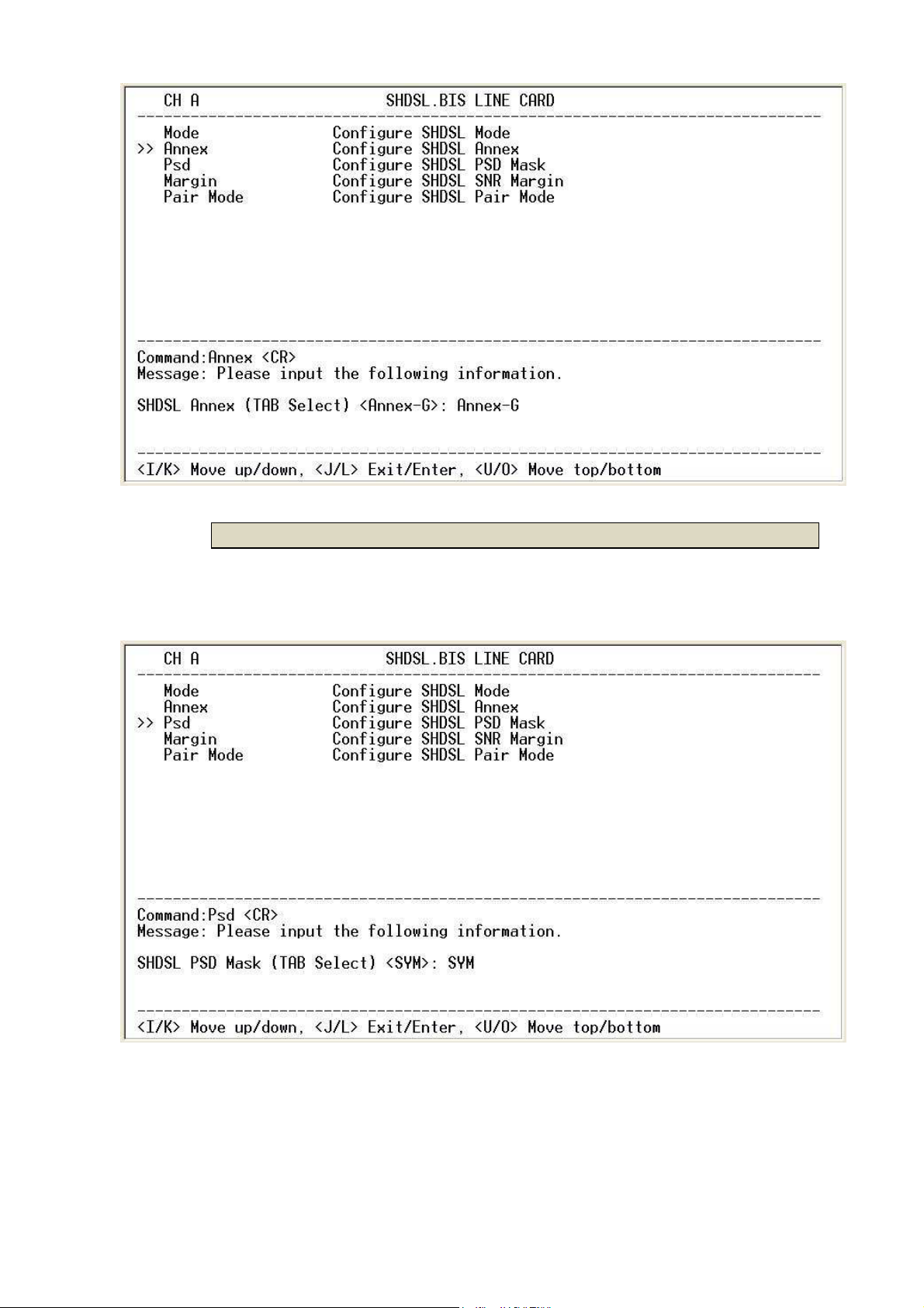
3.6.3.2 Annex
The 'Annex' setting refers to Annex A (ANSI), Annex B (ETSI), Annex F or Annex G
setting of the SHDSL.bis . The preferred and default setting is Annex G. However,
when you set the Annex, the CPE side device must match the same Annex as
the setting of the CO side line card.
43
Page 44
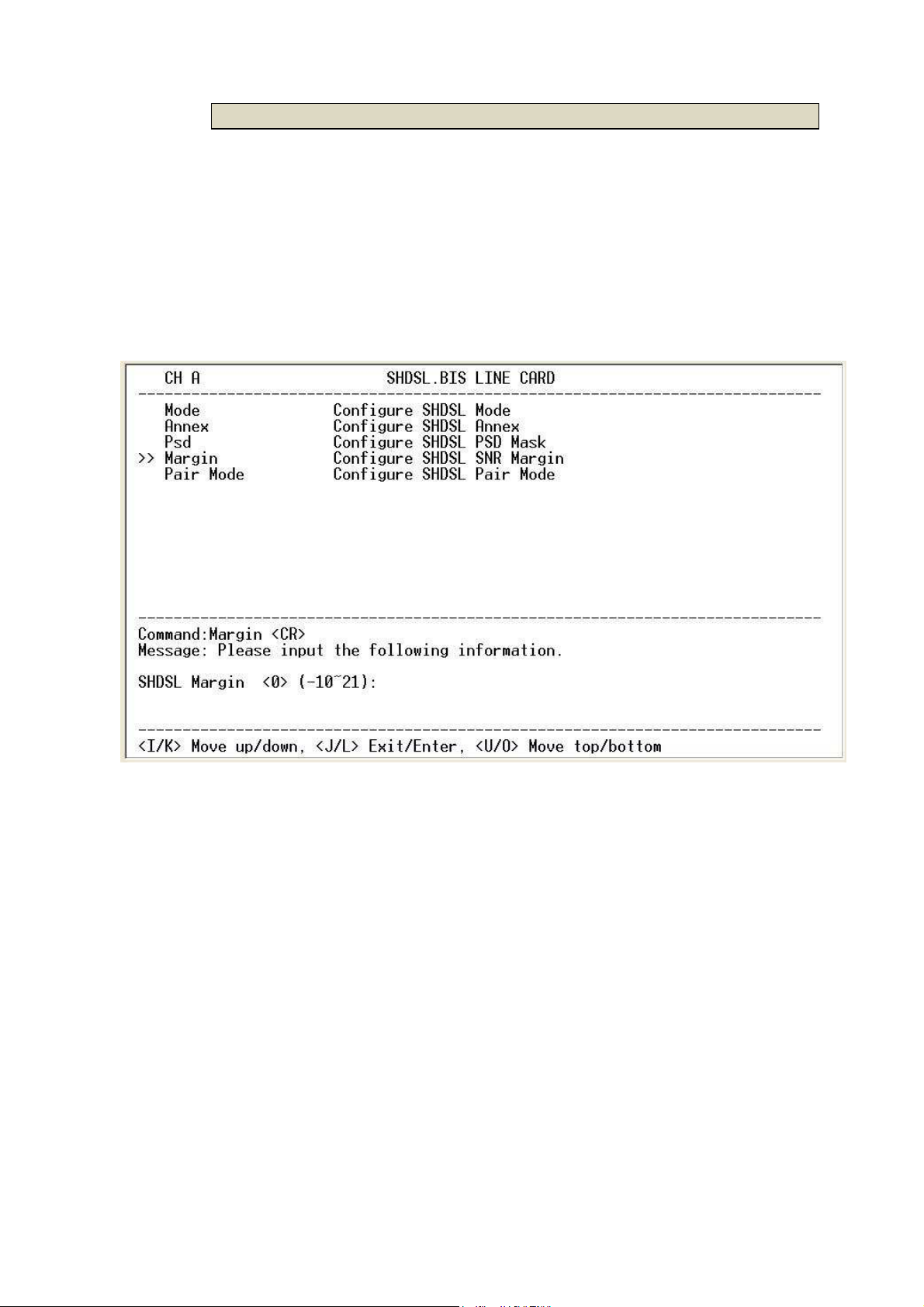
3.6.3.3 Psd
There are two type of PSD mask can select: SYM and for ASYM. The preferred
and default setting is SYM.
44
Page 45
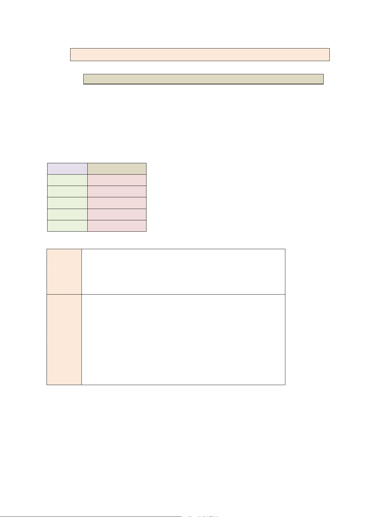
3.6.3.4 Margin
SHDSL SNR (Signal to Noise Ratio) margin: the margin range setting is from -10
to 21. Default is 0. SNR margin is an index of line connection quality. You can
see the actual SNR margin in STATUS SHDSL. The larger the SNR margin, the
better the line connection. If you set the SNR margin in the setting field as 3, the
SHDSL.bis connection will drop and reconnect when the SNR margin is lower
than 3. This will allow the device to reduce the line rate (if rate adaptive setting
is active) and reconnect for a better line connection.
45
Page 46

3.6.3.5 Pair Mode
You can select one pair or two pair mode.
SHDSL parameter setting:
SETUP SHDSL Selection items
STU-C-INTCLK,
MODE
STU-C-EXTCLK
ANNEX A, B, F, G
PSD SYM, ASYM
MARGIN
-10 to 21
PAIR MODE 1 Pair, 2 Pair
46
Page 47
bits pattern to establish
frame
3.6.4 Setup - E1 interface
3.6.4.1 Channel
Framing is required to recover the channelized E1. In transparent operation,
the framing is configured as Unframed. In this case the G.SHDSL framer must be
set to Nx64 with N=32. For any framing such as FAS or CAS, the G.SHDSL framer
must be set to E1, then the E1 framing here may be set accordingly.
The cross reference table between Channel and Framing:
Channel Framing
PCM31 FAS
PCM31C FAS+CRC4
PCM30 FAS+CAS
PCM30C FAS+CAS+CRC4
FULL Unframed
Frame Alignment Signal uses a 7-
and maintain the frame synchronization. The FAS word
FAS
is located in timeslot 0 of frame. In FAS mode there are
1~31 timeslot available for use data.
Also known as time slot 16 multi-framing. It requires a
multi-framing alignment signal to be present for frame
sync. The Multi-frame Alignment Signal (MFAS) is
inserted into the 16th timeslot of frame 0 of the 16-
CAS
multi-frame.
In CAS mode, there are 30 channels available for user
data. If timeslot 16 is included in the unit’s mapping, it
will be disregarded.
47
Page 48
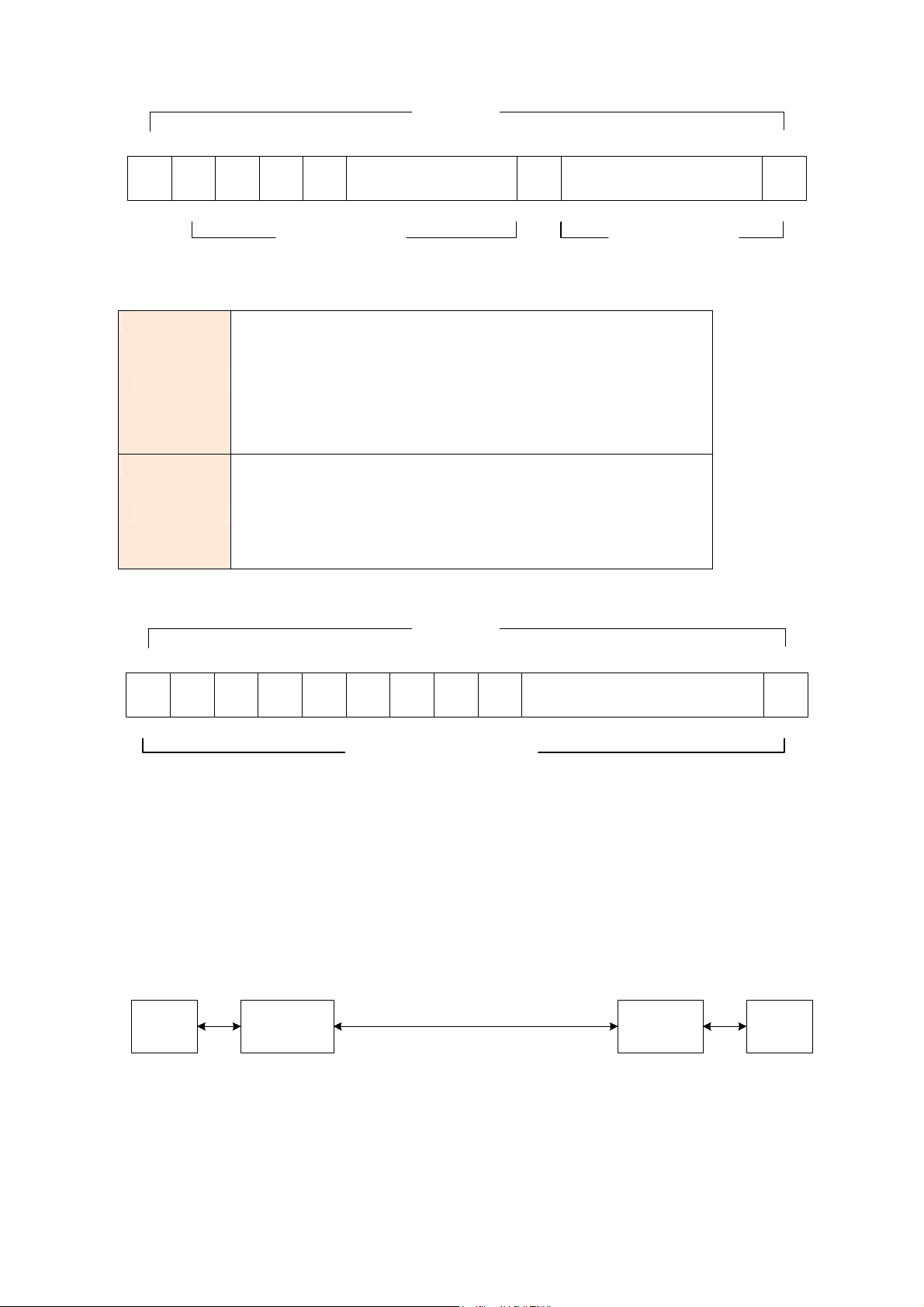
object of running without framing is to utilize the full
Time Slots
0 1 2 3 4 16
FAS
64k 64k 64k 64k 64k 64k 64k896k
Data Rate (x) 960kbps Data Rate (y) 960kbps
The CRC-4 checksum bits are transmitted in the
5 ~ 15
CAS
704k
Maximun Data Rate = x + y = 1920kbps
outgoing E1 data stream. Also the received signal
CRC4
is checked for errors.
CRC-4 checksum cannot be sent in unframed
mode.
In this mode, user data is inserted into all 32
channels (64k x 32 = 2048k) of the E1 stream. The
Unframed
bandwidth of the E1 line.
Time Slots
17 ~ 30
31
0 1 2 3 4 5 6 7
64k 64k 64k 64k 64k 64k 64k 64k 64k 64k1408k
Maximun Data Rate 2048kbps
8 31
9 ~ 30
ITU 991.2 (2004) (G.SHDSL .Bis) supports data rate up to 5696Kbps, but G.703
(E1 standard) only supports data rate of 2048kbps so the maximum data rate
of SHDSL line, connected with E1 DCEs, depends on data rate of E1,
2048kbps.
E1 SHDSL
STU-C (E1)
Frame E1
Data rate # of TS
STU-R (E1) DTEDTE
E1
If the connection is E1 vs V.35 or V.35 vs E1, the frame has to be used N x 64k. In
this case, the data rate depends on value of N. Same as above case, SHDSL
and V35 can support up to 5696kbps data rate, but E1 supports maximum
48
Page 49
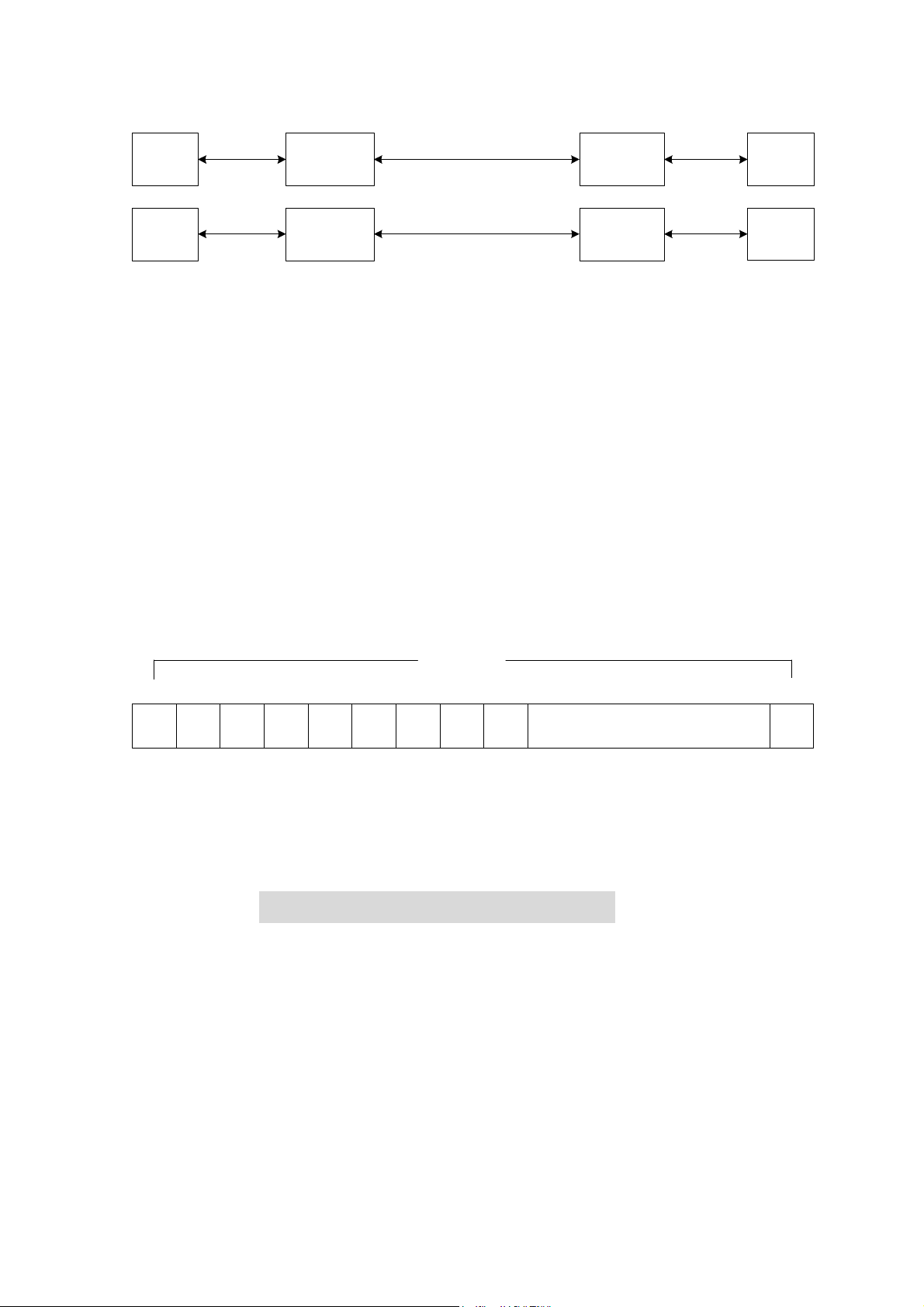
data rate of 2048kbps (32 x 64k).
E1 SHDSL
STU-C (E1)
Unframed N=32
V.35 SHDSL
STU-C (V.35)
Frame N x 64 (N=1~31)
STU-R
(V.35)
STU-R (E1) DTEDTE
V.35
E1
DTEDTE
Time slots, N value, are placed in the frame. If time Slot Number is1 from 1~31
(N=1~31), it is Fractional E1. If time Slot Number is 32 (N=32), it is unframed.
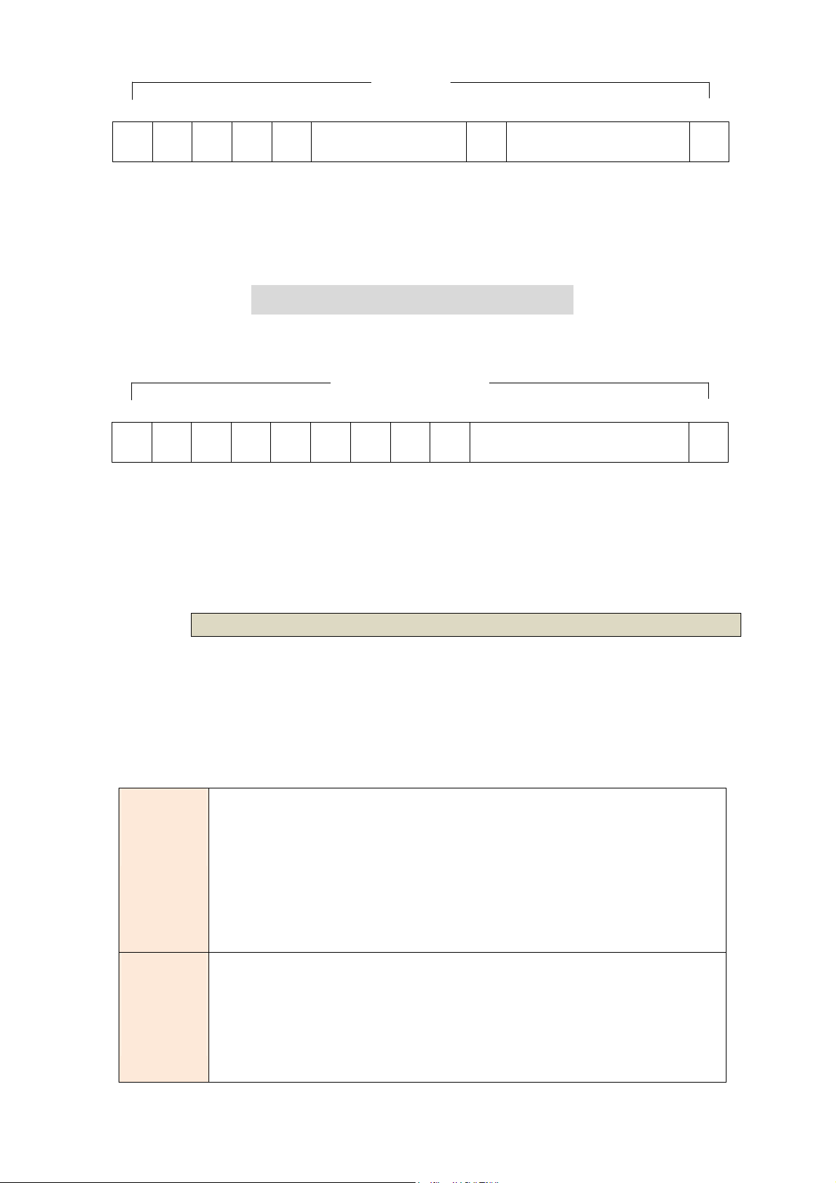
Fractional E1
For fractional E1(FE1), the data rate is from 64k(N=1) to 1984k(N=31), according
to the E1 framing. If the E1 frame is PCM31(FAS) or PCM31C(FAS+CRC4), there
are 1~31 available time slot for use data. For example, if the data rate of SHDSL
line set to be 512k, the time slot number is 8 and first time slot number is 1. The
frame is shown as below.
Time Slots
0 1 2 3 4 5 6 7
FAS Data Data Data Data Data Data Data Data
64k 64k 64k 64k 64k 64k 64k 64k 64k 64k1408k
8 31
9 ~ 30
The First Time Slot setting of PCM31(FAS) and PCM31C(FAS+ CRC4) have to
follow the rule:
First Time Slot ≦ 31 - Time Slot Number
Using the E1 framing of PCM30(FAS+CAS) or PCM30C(FAS+CAS+CRC4), the
FAS will occupy Time Slot 0 and CAS Time Slot 16. There are only 30 Time Slot left
for data. On the other hand, the data rate is 1920kbps.
49
Page 50
m as zeros. This method enables the network
Alternate Mark Inversion defines a pulse as a “mark,” a binary
signals are transmitted as a sequence of one and zero. One is
Time Slots
0 1 2 3 4 16
FAS
64k 64k 64k 64k 64k 64k 64k896k
5 ~ 15
CAS
704k
17 ~ 30
31
The First Time Slot setting of PCM30(FAS+CAS) and PCM30C(FAS+CAS+CRC4)
have to follow the rule:
First Time Slot ≦ 30 - Time Slot Number
Unframed E1
Time Slots
0 1 2 3 4 5 6 7
Data Data Data Data Data Data Data Data Data Data Data
64k 64k 64k 64k 64k 64k 64k 64k 64k 64k1408k
8 31
9 ~ 30
In Unframed E1, user data are inserted into all 32 channels (64k x 32 = 2048k) of
the E1 stream. The object of running without framing is to utilize the full
bandwidth of the E1 line.
3.6.4.2 Code
The E1 line card supports two different line codings. HDB3 is the most popular
and preferred line coding and is also the default setting. AMI line coding is also
selectable.
HDB3
In this line coding, the transmitter substitutes a deliberate
bipolar violation when excessive zeros in the data stream are
detected. The receiver recognizes these special violations
and decodes the
to minimize pulse density requirements. Unless AMI is required
for your application, HDB3 should be used whenever possible.
one, as opposed to a zero. In an E1 network connection,
AMI
sent as pulse, and zero is sent as spaces, i.e. no pulse. Every
other pulse is inverted from the previous pulse in polarity, so
50
Page 51
that the signal can be effectively transmitted. This means,
however, that a long sequence of zeros in data stream will
cause problems, since the NTU receiving the signal relies on
the signal to recover the 2048kbps clock.
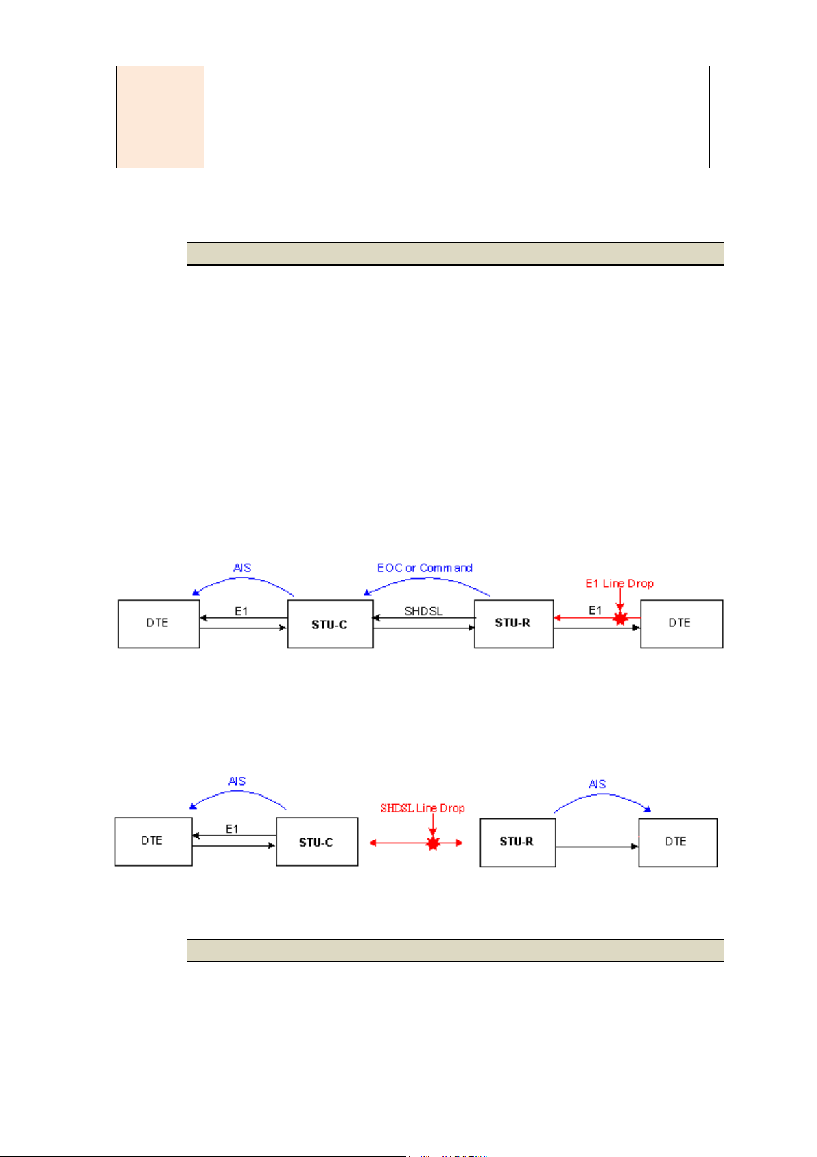
3.6.4.3 Ais
AIS or Alarm Indication Signal is a method to inform the remote connection
that there is a signal or sync problem with the E1. AIS is only valid in framed
mode E1, not in Unframed E1. The setting here of AIS enabled (on) or not (off)
and is for testing with AIS. When enabled, the E1 will transmit the AIS and it
should be confirmed at the remote device (AIS indication lit). After testing,
please turn AIS back off.
Example 1: When STU-R E1 RX line is dropped, STU-R sends the status to
STU-C via EOC or command, and then STU-C will send AIS (Alarm
Indication Signal) to DTE while AIS function is enabled.
Example 2: When SHDSL connection drops, STU-R and STU-C both send AIS
(Alarm Indication Signal) to DTE in the same time while AIS function is
enabled.
3.6.4.4 Build outs
The E1 line card supports both unbalanced E1 at 75 ohms and balanced E1 at
120 ohms. The settings for impedance are made here under the build out
menu setting.
51
Page 52
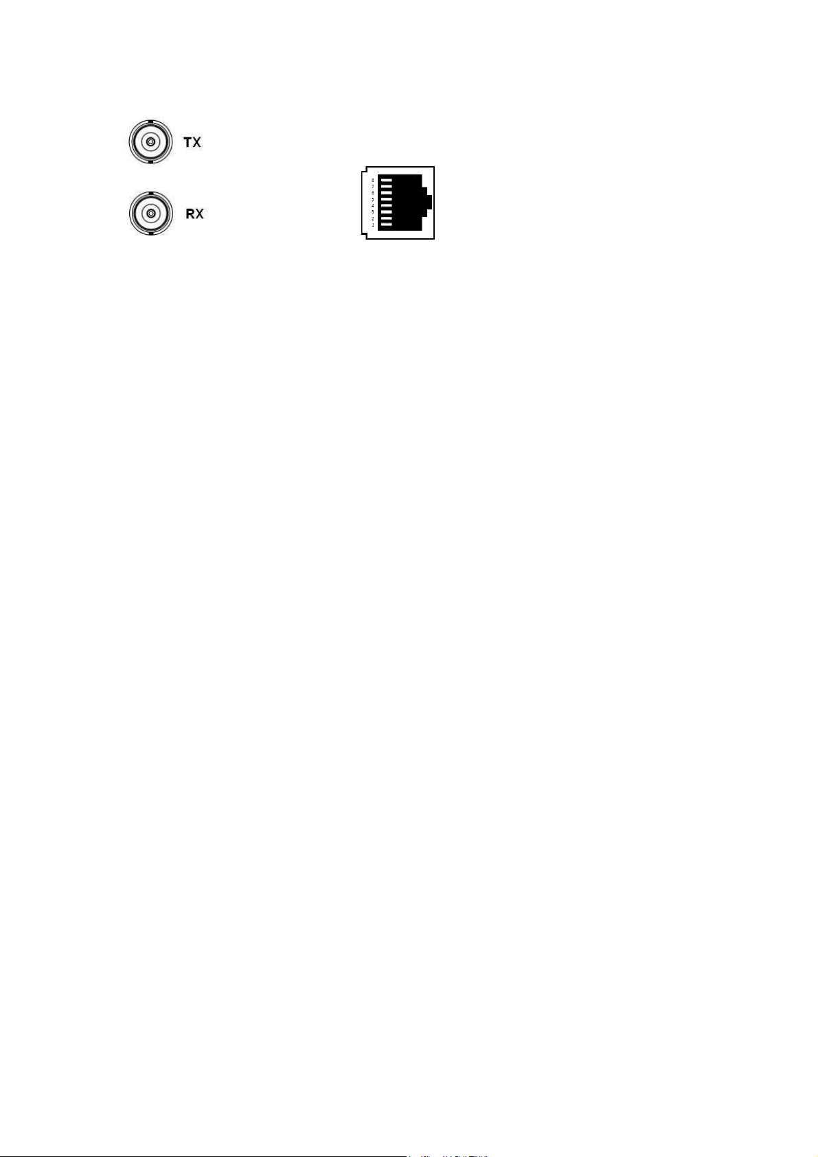
75 Ohms 120 Ohms
BNC Connector RJ-45 Connector
52
Page 53
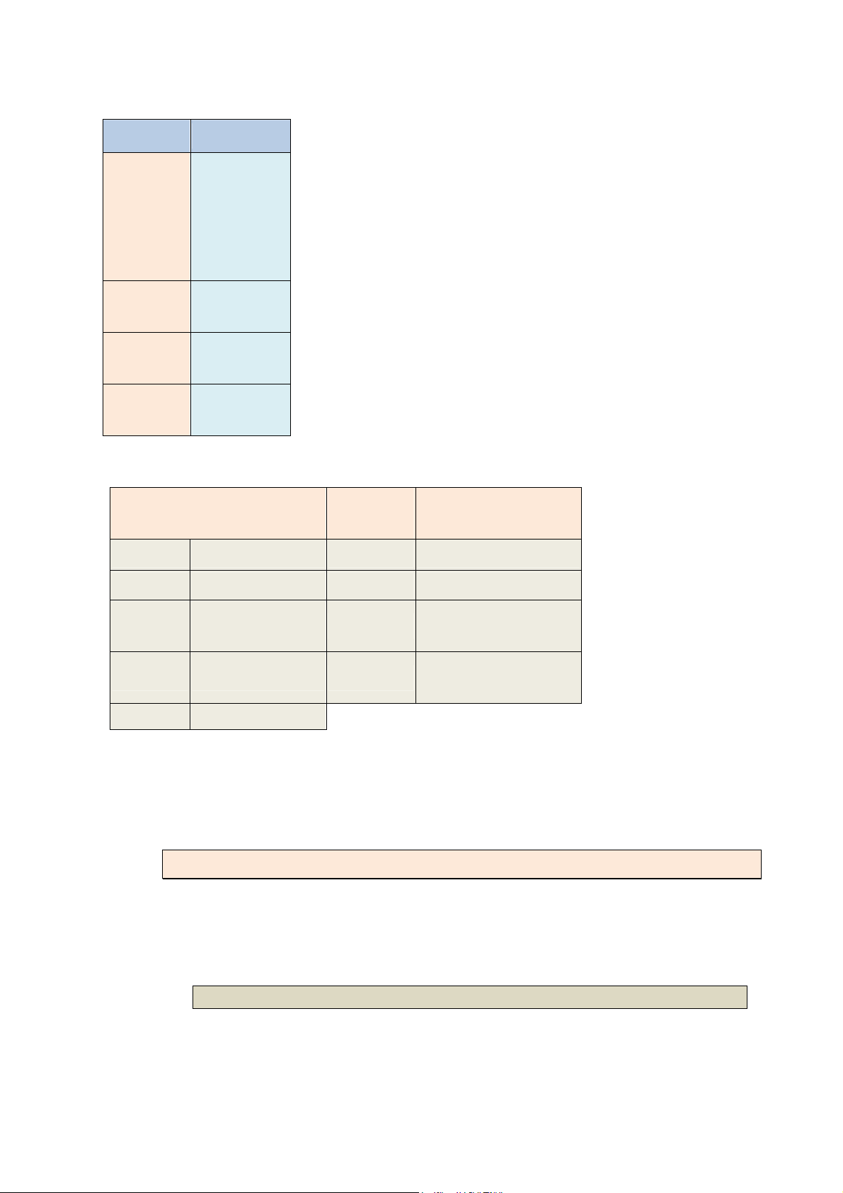
E1 parameter setting:
E1 Items Setting
PCM31
PCM31C
Channel
PCM30
PCM30C
FULL
HDB3
Code
AMI
On
AIS
Off
120 ohms
Build Outs
75 ohms
Framer Setting:
Slot
Framer
Number
PCM31 FAS 1 to 31 1 to 31
PCM31C FAS+CRC4 1 to 31 1 to 31
1 to 31 (cannot use
PCM30 FAS+CAS 1 to 30
16)
First Slot
PCM30C FAS+CAS+CRC4 1 to 30
1 to 31 (cannot use
16)
FULL UNFRAMED
3.6.5 Setup – Serial interface
The serial settings include the interface mode, data rate, clocking and
handshaking lines setup.
3.6.5.1 Interface
The serial line card supports both V.35 interface and RS-530(X.21) interface.
53
Page 54
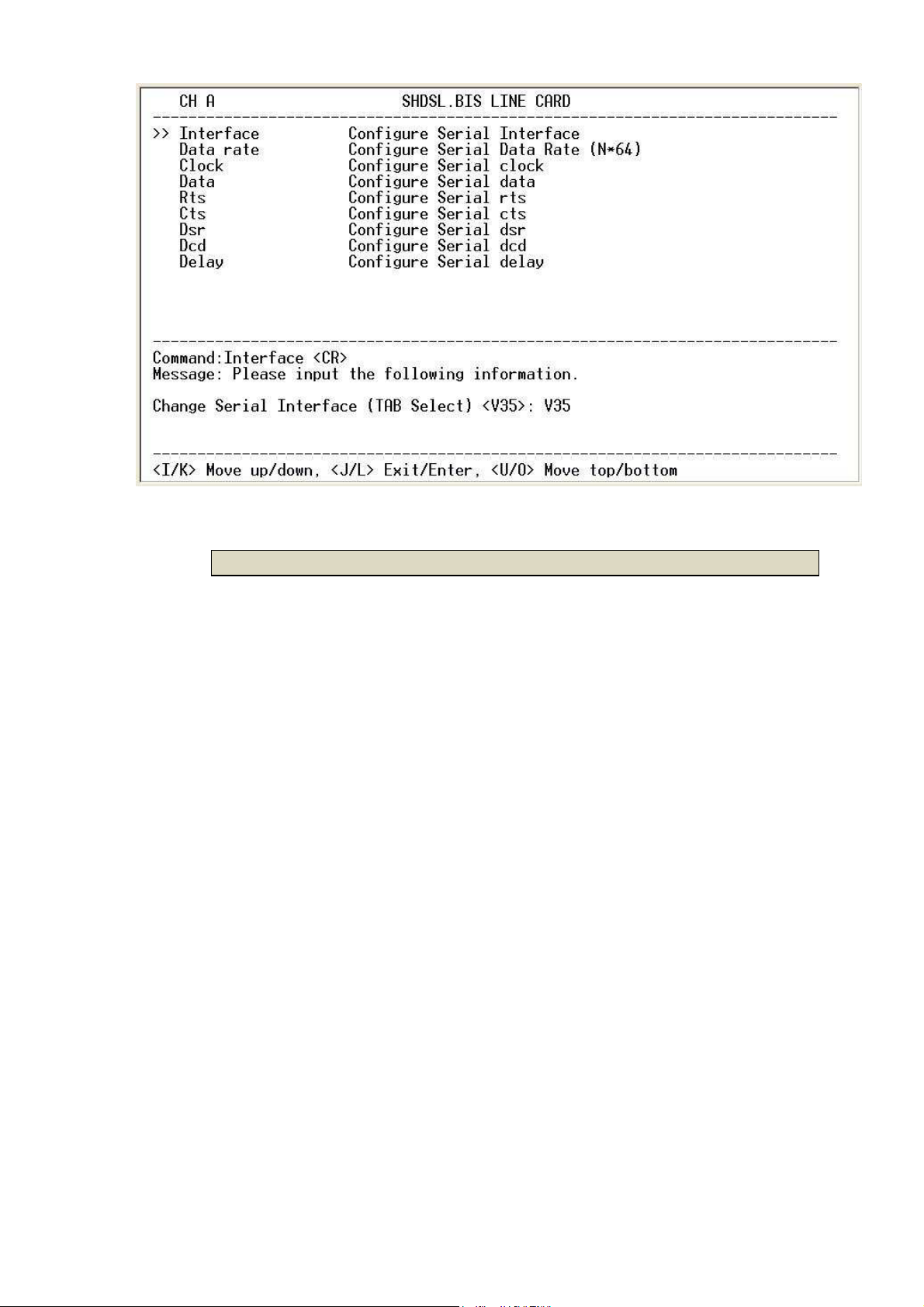
3.6.5.2 Data rate
For 2-wires with Annex A and B, the rate can be adjusted in increments of
64kbps from 64kbps to 2304kbps (N=1~36).
For 2-wires with Annex F and G, the rate can be adjusted in increments of
64kbps from 64kbps to 5696kbps (N=1~89).
For 4-wires with Annex A and B, the rate can be adjusted in increments of
64kbps from 128kbps to 4608kbps (N=2~72 , even number only).
For 4-wires with Annex F and G, the rate can be adjusted in increments of
64kbps from 128kbps to 8192kbps (N=2~128, even number only ).
54
Page 55
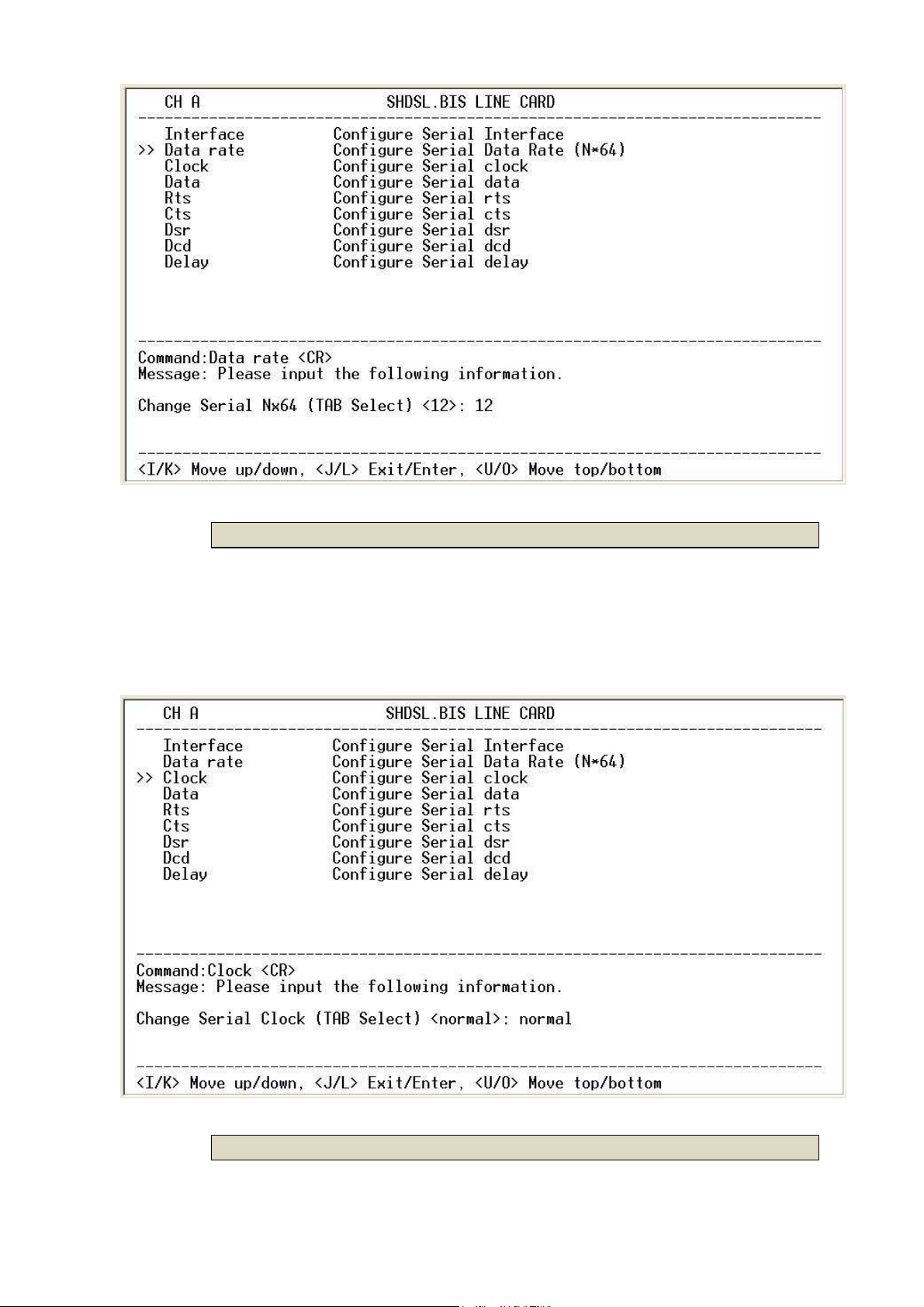
3.6.5.3 Clock
The data port clock polarity may be adjusted to solve some clocking issues.
The default setting is 'Normal' clock polarity, where data is sent on the positive
transition of the clock, while the option exists to set inverse clock polarity where
data is sent on the negative clock transition.
3.6.5.4 Data
55
Page 56

The data polarity may be adjusted to solve some data transfer issues. The
default setting is 'Normal' data polarity, where data is sent on the negative
transition, while the option exists to set inverse data polarity where data is sent
on the positive transition.
3.6.5.5 Rts
The behavior of the RTS (Request To Send) signal may be set in one of two
ways. When set 'on', the RTS signal is always forced high (on, positive voltage or
SPACE), when set 'from dte' the RTS signal will follow the DTE's condition. The
default setting for RTS is from DTE.
56
Page 57

3.6.5.6 Cts
The behavior of the CTS (Clear To Send) signal may be set in one of three ways.
When set 'on', the CTS signal is always forced high (on, positive voltage or
SPACE), when set 'off' the signal is always forced low (off, negative voltage or
MARK), or CTS will follow RTS (Request To Send) condition of 'on' for RTS on or
'off' for RTS off. The default setting for CTS is to follow RTS.
57
Page 58
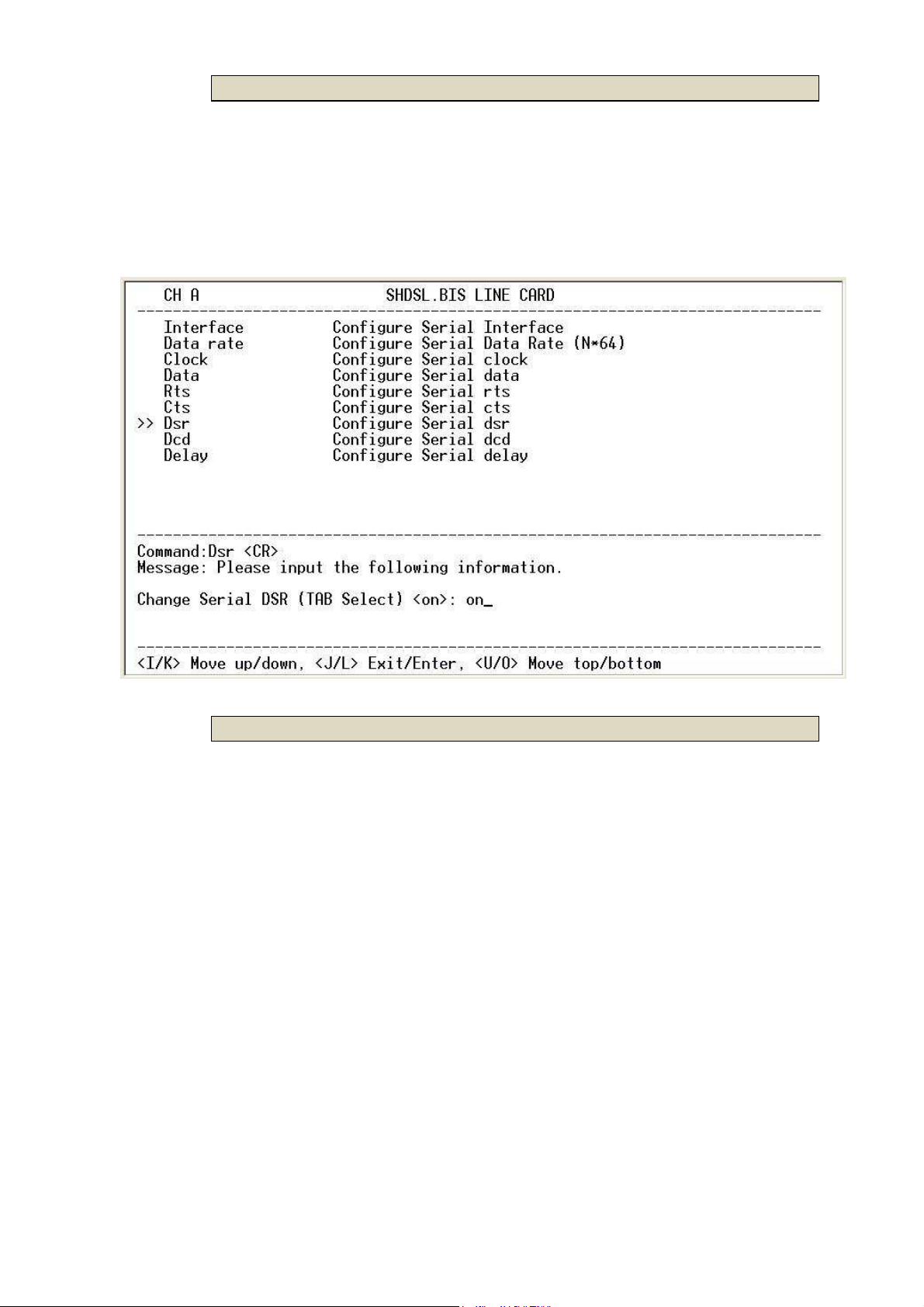
3.6.5.7 Dsr
The behavior of the DSR (Data Set Ready) signal may be set in one of three
ways. When set 'on', the DSR signal is always forced high (on, positive voltage
or SPACE), when set 'off' the signal is always forced low (off, negative voltage
or MARK), or DSR will follow DTR (Data Terminal Ready) condition of 'on' for DTR
on or 'off' for DTR off. The default setting for DSR is to follow DTR.
3.6.5.8 Dcd
The behavior of the DCD (Data Carrier Detect) signal may be set in one of
three ways. When set 'on', the DCD signal is always forced high (on, positive
voltage or SPACE), when set 'off' the signal is always forced low (off, negative
voltage or MARK), or DCD will follow the DSL condition of 'on' for DSL link or 'off'
for no link. The default setting for DCD is to follow the DSL link status.
58
Page 59

59
Page 60

The handshake signal direction between DCE and DTE
V.35 Interface Line Card
SHRM03b-V35
The below diagram shows CTS follow RTS, DSR follow DTR
V.35 Interface Line Card
SHRM03b-V35
3.6.5.9 Delay
The delay setting is used to cause a delay for CTS to follow RTS. The delay
setting may be set from 0 to 3 milliseconds. The default setting is 3 milliseconds.
60
Page 61
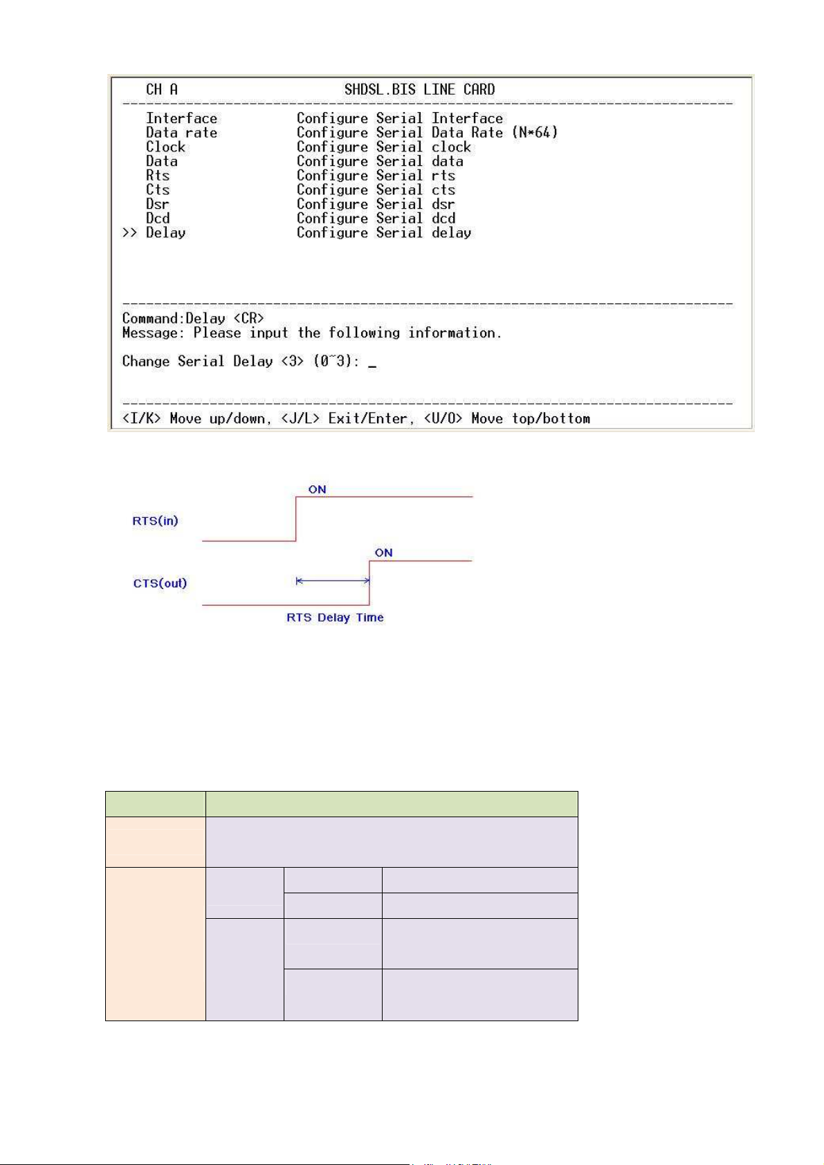
The RTS delay time is use to control CTS on delay to RTS signal, It works only for
the setting:
CTS follow RTS and RTS follow from DTE .
V.35 Interface control signals settings table:
Serial Items Setting
V.35
INTERFACE
X.21(RS-530)
Annex A/B 1 ~ 36
2-wires
DATA RATE
(Nx64K
mode)
4-wires
Annex F/G 1 ~ 89
Annex A/B 2 ~ 72 (even number
only)
Annex F/G 2 ~ 128 (even number
only)
61
Page 62
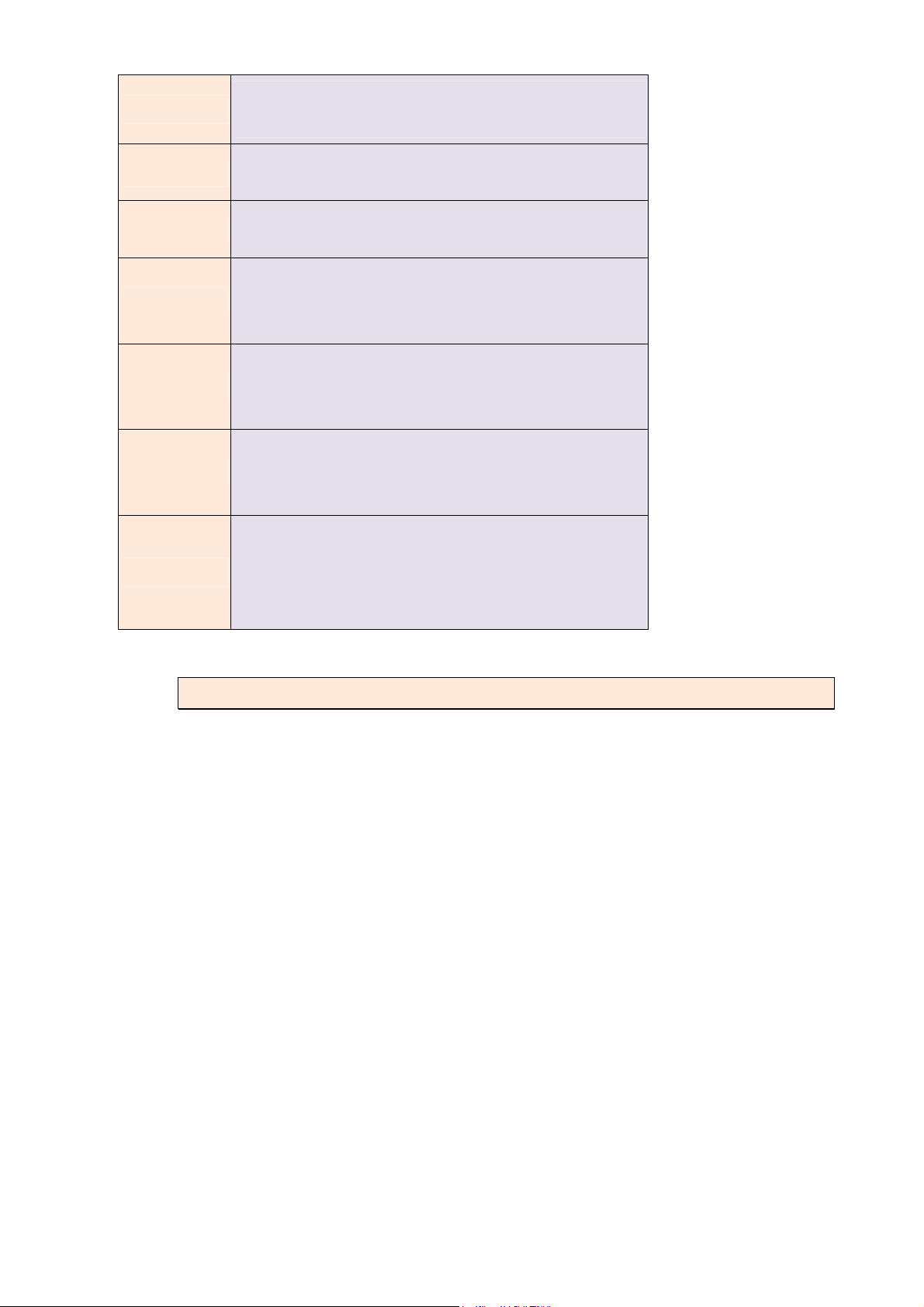
CLOCK
DATA
RTS
CTS
DSR
DCD
Normal
Inverse
Normal
Inverse
On
From DTE
On
Off
From RTS
On
Off
From DTR
On
Off
From DSL
0mS
DELAY
1mS
2mS
3mS
3.6.6 Setup – Ethernet interface
The Ethernet settings include the data rate, negotiation, duplex the speed.
Date Rate
62
Page 63
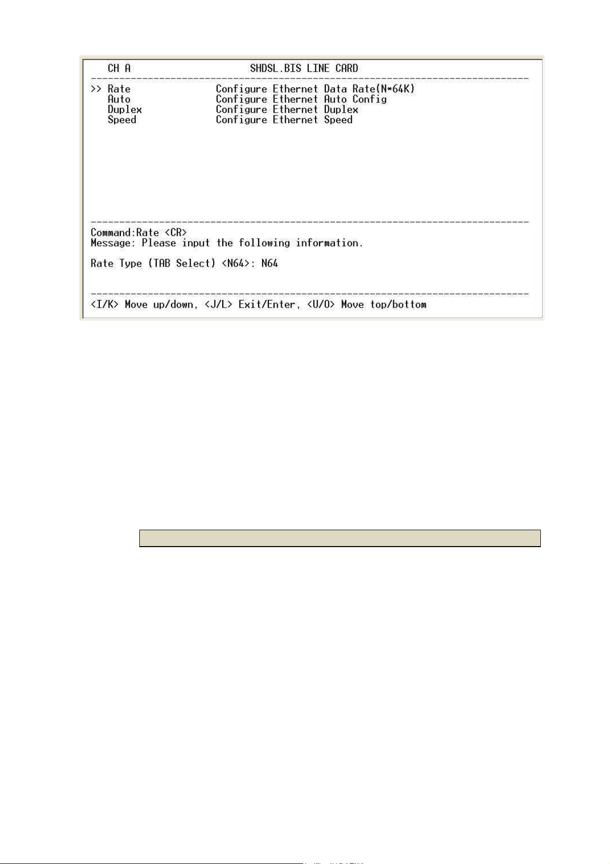
For 2-wires with Annex A and B, the rate can be adjusted in increments of
64kbps from 64kbps to 2304kbps (N=1~36).
For 2-wires with Annex F and G, the rate can be adjusted in increments of
64kbps from 64kbps to 5696kbps (N=1~89).
For 4-wires with Annex A and B, the rate can be adjusted in increments of
64kbps from 128kbps to 4608kbps (N=2~72, even number only).
For 4-wires with Annex F and G, the rate can be adjusted in increments of
64kbps from 128kbps to 11392kbps (N=2~178, even number only).
3.6.6.1 Negotiation
You can select Enable and Disable on auto negotiation function. I
63
Page 64
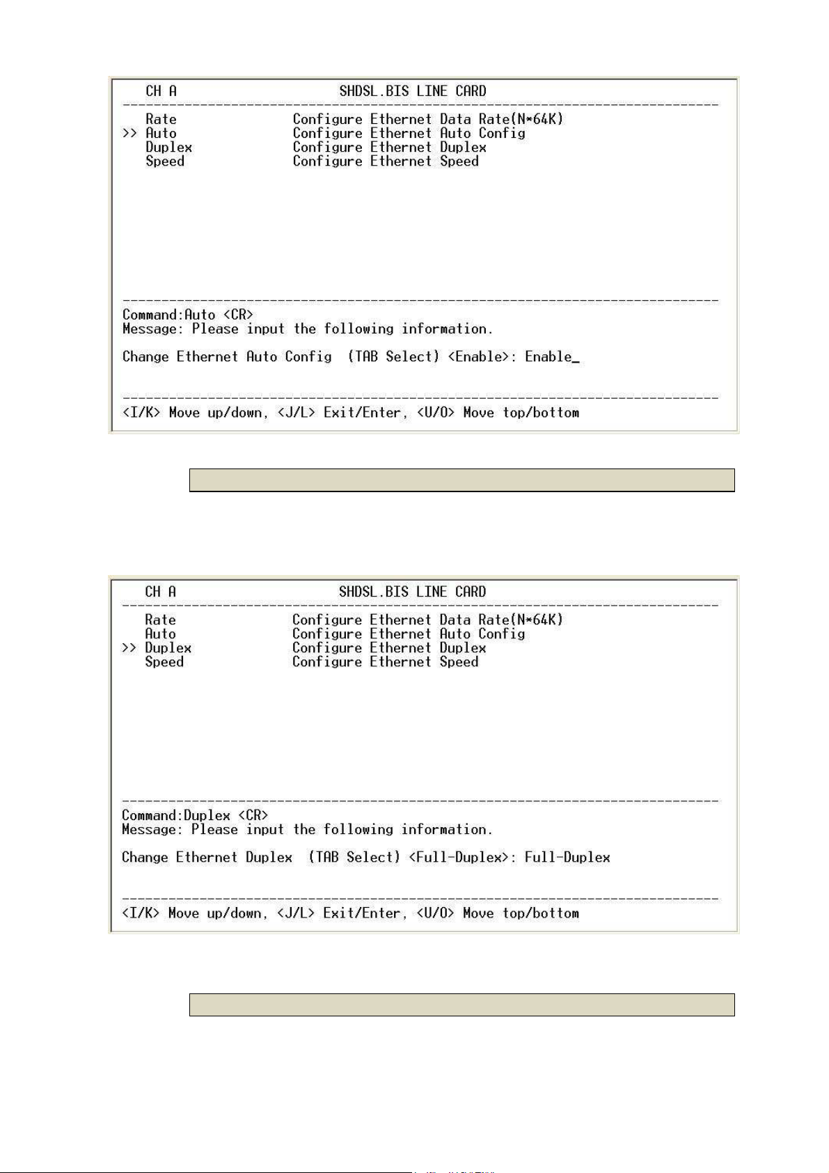
3.6.6.2 Duplex
When auto negotiation setup is Disable, there has to be a selection of duplex
mode: Full-Duplex and Half-Duplex.
3.6.6.3 Speed
When auto negotiation is Disable, there has to be selection on speed setting:
64
Page 65
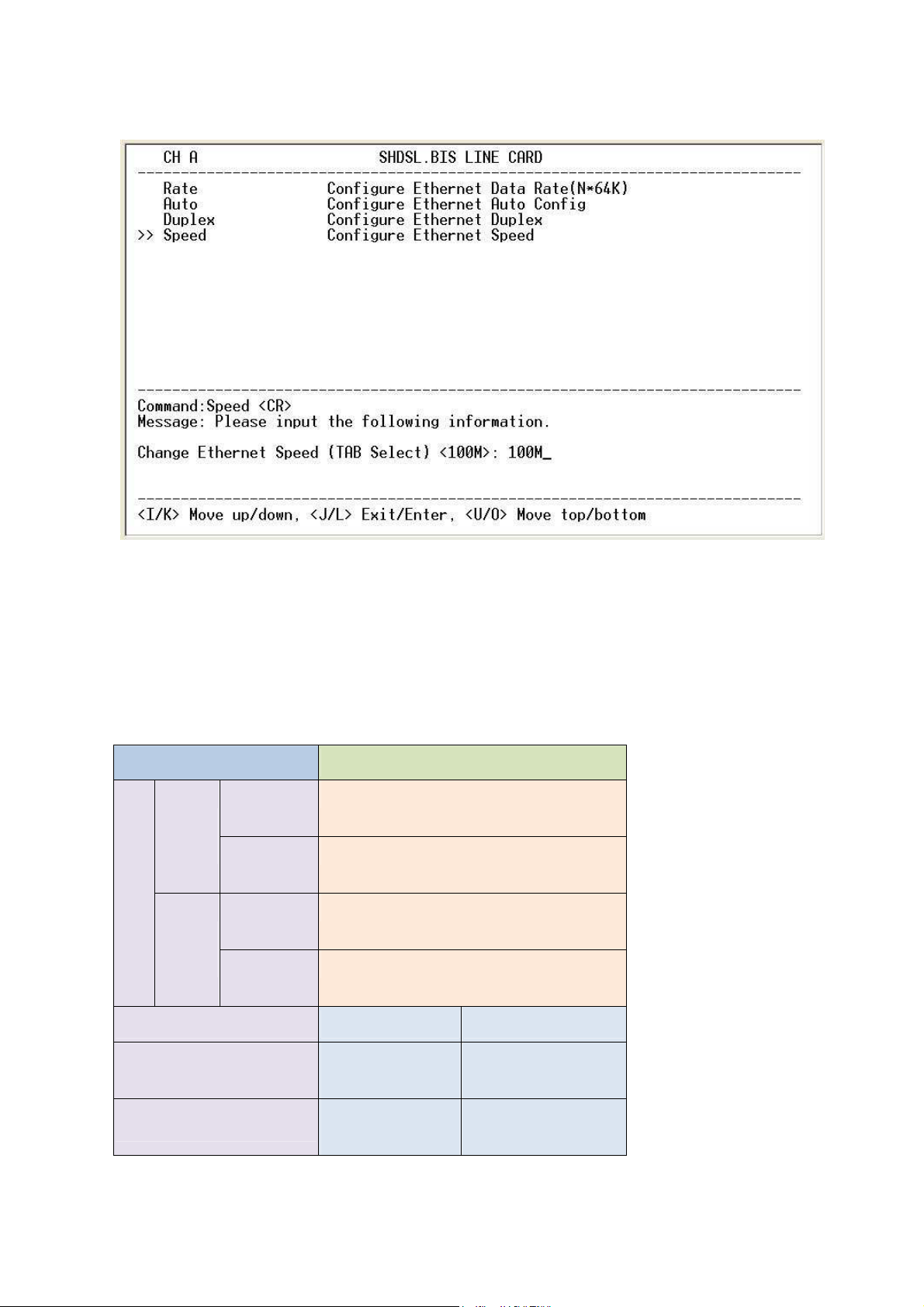
10M and 100M.If auto negotiation is Enable, the items Duplex and Speed
cannot be set. The message will display “Ethernet is in auto negotiate”
If you set Ethernet Auto Negotiation as Enable, the default setting on Duplex is
Full and Speed is 100M.
If you set Ethernet Auto Negotiation as Enable, the Duplex and Speed cannot
be set up and it will use auto configuration.
Ethernet parameter setting:
Ethernet Items Setting
Rat
e
2-wire
s
4-wire
s
Annex
A/B
Annex
F/G
Annex
A/B
Annex
1 ~ 36
1 ~ 89
2 ~ 72 (even number only)
2 ~ 178 (even number only)
F/G
Auto Disable Enable
Full-Duplex
Auto
Duplex
Half-Duplex
100M
Configuration
Auto
Speed
10M
Configuration
65
Page 66
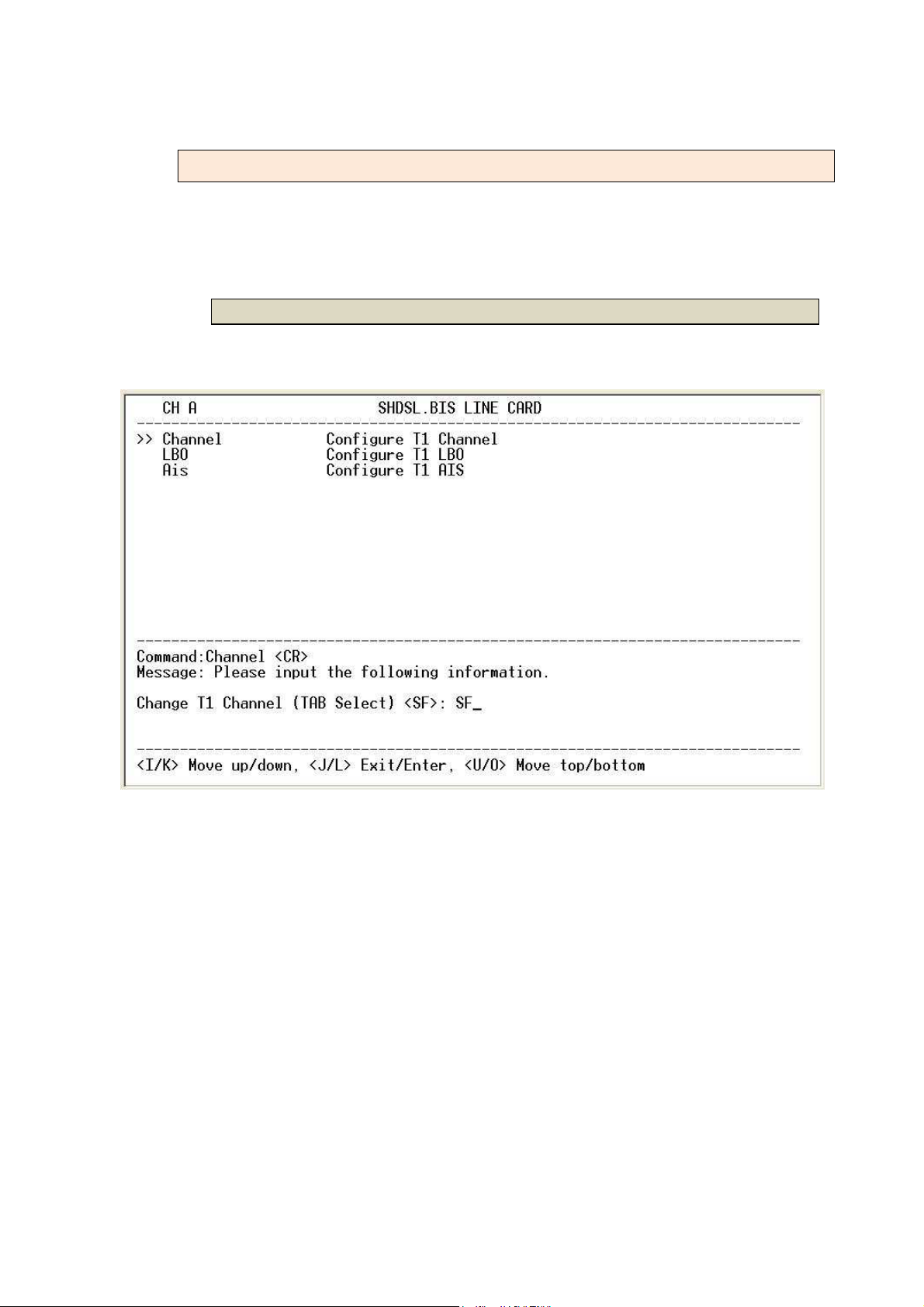
3.6.7 Setup – T1 interface
The T1 settings include the Channel, Number of time slots , First time slots, LBO
and AIS.
3.6.7.1 Channel
The T1 interface can be programmed to encode/decode its transmit/receive
signals using Bipolar with Eight Zero Suppression (B8ZS) coding.
Each T1 frame contains 1 byte of voice data for each of the 24 channels, that
system needs then 8000 frames per second to maintain those 24 simultaneous
voice channels. Because each frame of a T1 is 193 bits in length (24 channels X
8 bits per channel + 1 framing bit = 193 bits), 8000 frames per second is
multiplied by 193 bits to yield a transfer rate of 1.544 Mbit/s (8000 X 193 =
1544000).
The T1 format provides a 64 Kbps channel for each of 24 individual channels.
Each of these channels is called a DS-0 channel or a time slot and consists of
an eight-bit sample. A T1 frame is constructed by time division multiplexing
these 24 time slots and inserting a framing bit at the beginning of the series. This
66
Page 67
results in 192 bits of channel data, plus a framing bit (F-bit), for a total of 193 bits
in a frame. Multiple frames are then grouped into superframes of 12 or 24
frames to provide for framing synchronization and signaling.
The Superframe(SF) (also called D4 or 193S) format defines a superframe as 12
frames.
The Extended Superframe (ESF) (also called 193E) format groups 24 frames into
its superframe.
Both the SF and ESF framing formats provide an actual payload data rate of
1.536 Mbps (192/193 = 1.536/1.544).
For fractional T1 , the data rate is from 64k(N=1) to 1536k(N=24), according to
the T1 framing.
When SHDSL.bis using 2-pairs(4-wires), the time slot number can only use even
number
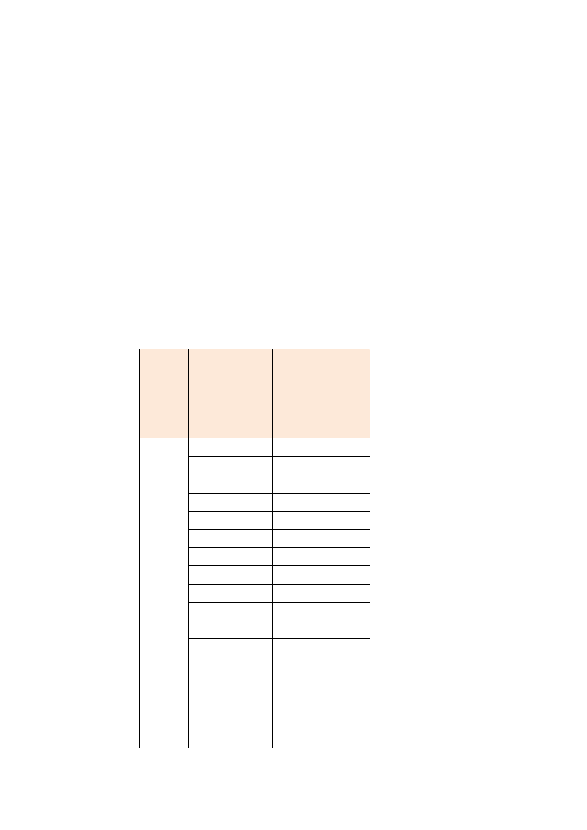
The table of number of time slot vs. 1st time slot:
Chann
Number of 1st slot
el
SF
ESF
24 1
23 1~2
22 1~3
21 1~4
20 1~5
19 1~6
18 1~7
17 1~8
16 1~9
15 1~10
14 1~11
13 1~12
12 1~13
11 1~14
10 1~15
9 1~16
8 1~17
67
Page 68
7 1~18
6 1~19
5 1~20
4 1~21
3 1~22
2 1~23
1 1~24
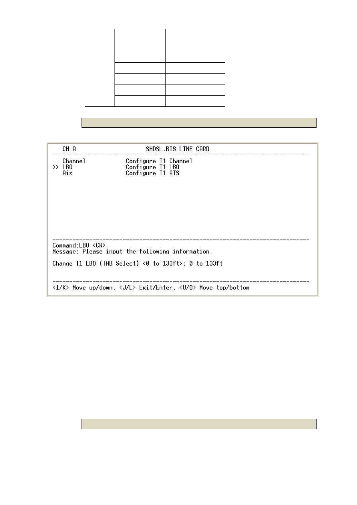
3.6.7.2 LBO
LBO(Line build-out) setting are an inherent part of T1 network element
transmission circuitry. Because cable lengths between T1 device and NTU are
vary, LBO settings are designed to adjust the output power of the transmission
signal to achieve equal level point (ELP) at the NTU.
For short distance of T1 cable, this device must decreases outgoing signal
strength.
There are five type T1 LBO for your select : 0 ~133ft , 133 ~ 266ft , 266 ~399 ft ,
399 ft ~ 533ft , 533ft ~ 655ft
3.6.7.3 AIS
68
Page 69

AIS (Alarm Indication Signal) is a method to inform the remote connection that
there is a signal or sync problem with the T1.
T1 parameter setting:
T1 items Setting
SF
Channel
ESF
Unframed
Slot Number
First Slot
0~133ft
133~266ft
LBO
266~399ft
399ft~533ft
533~655ft
Off
AIS
On
3.6.8 Remote Config
You can set the “Enable/Disable function” to let the remote side configure
parameters to this device remotely.
69
Page 70
3.6.9 Default
The line card can have all settings restored to their original factory settings
simply by going to the setting menu, selecting the 'default' item, and then
press ENTER. The system will ask for a y(es) or n(o) confirmation followed by an
ENTER.
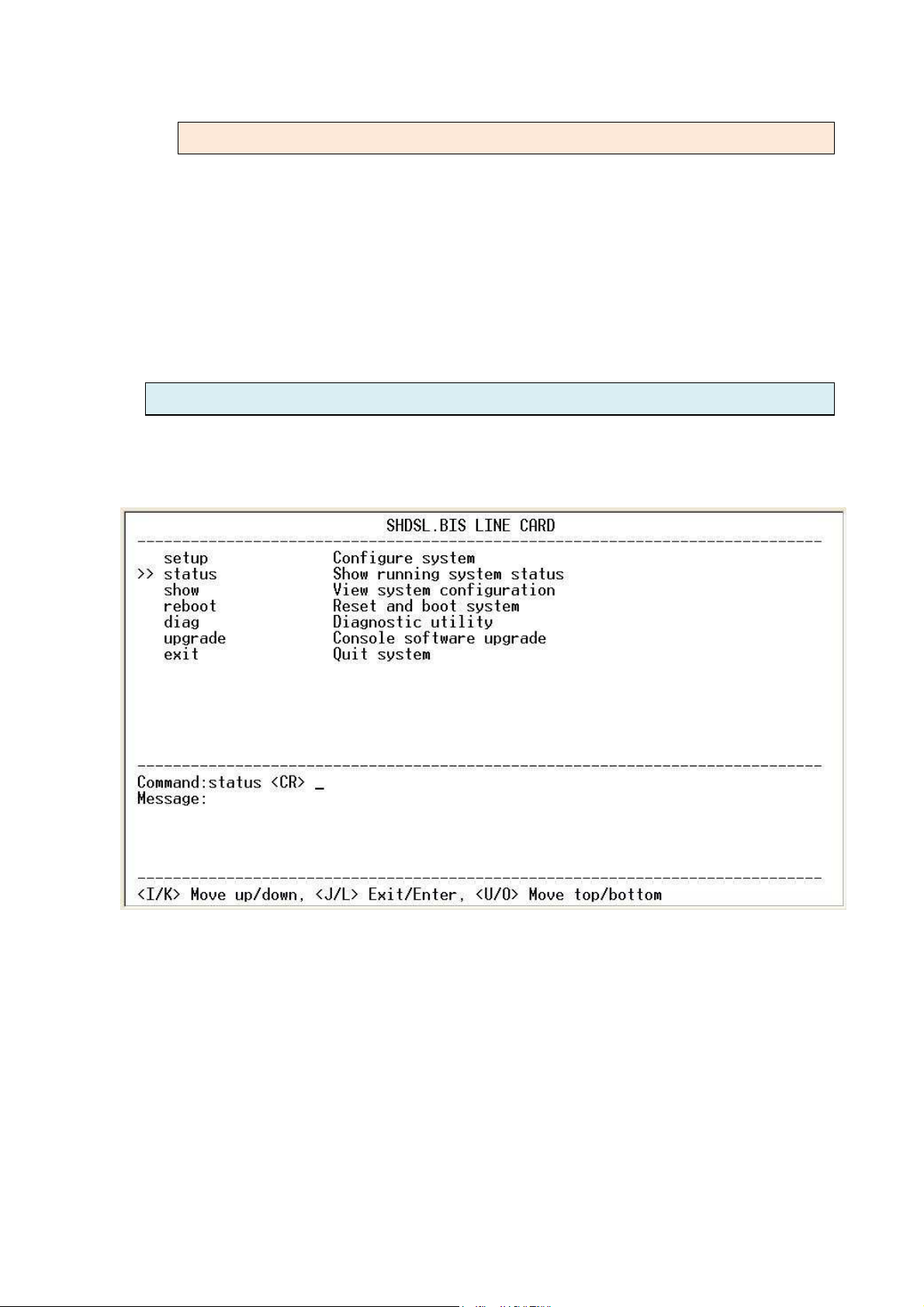
3.7 Status
From the main setup menu after logging in, arrow key down to select the
'status' menu item and then press the right arrow key or ENTER.
From the main Status Display menu press the right arrow or ENTER when the
cursor is on the shdsl menu item.
70
Page 71
3.7.1 Shdsl
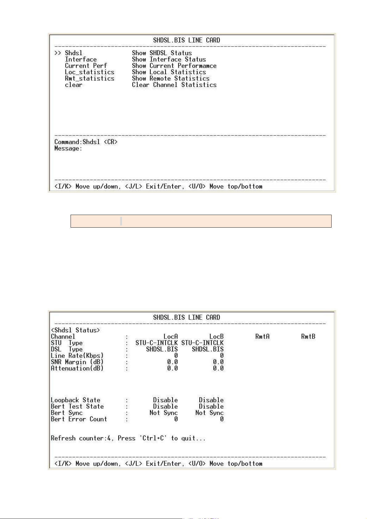
The shdsl status window will display a real-time status of the DSL for both
channels and remote CPE if connected. The screen is refreshed every 2
seconds. The monitoring window displays the DSL line parameters, such as STU
type, Line rate, SNR margin and attenuation. The lower half of the window
displays the loopback and BER test status. While in this display mode the
terminal window will not time out. To exit the window press CTRL-C.
71
Page 72
3.7.2 Interface
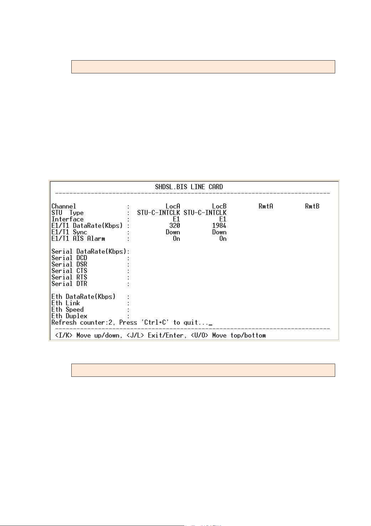
The interface status window will display a real-time status of the interface for
both channels and remote CPE if connected. The screen is refreshed every 2
seconds. The monitoring window displays the interface parameters, such as
STU type, interface type, there have E1 parameters, Serial parameters or
Ethernet parameters according which line card type to been used. While in
this display mode the terminal window will not time out. To exit the window
press CTRL-C.
3.7.3 Current Performance
72
Page 73
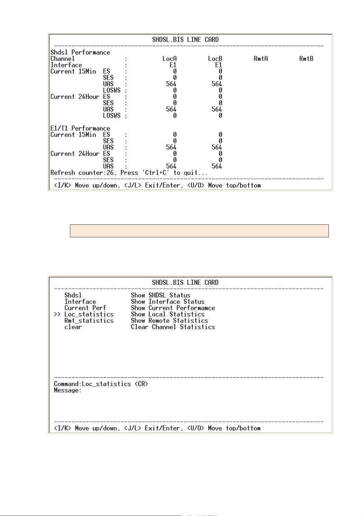
3.7.4 Statistics
After returning to the Status Display main menu, use the down arrow key to
select statistics. Press right arrow or ENTER.
The statistics display window will display performance monitor data for the
73
Page 74
selected channel (A or B) and for the selected interval (15 minutes or 24 hours).
The display will show the recorded results for the SHDSL.bis ES (error seconds),
SES (severely errored seconds), UAS (unavailable seconds), and LOSW (loss of
sync word) and for the G.703 E1/T1 ES (error seconds), SES (severely errored
seconds), UAS (unavailable seconds).
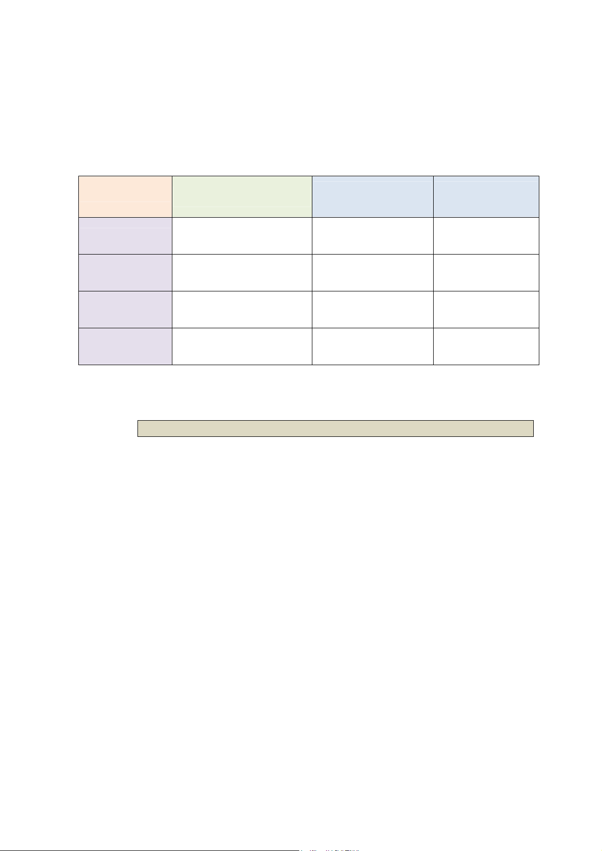
Model vs. Interface modes and statistics support:
Model
SHRM03bB
SHRM03b-V35
SHRM03b-ET100
Interface modes
support
E1 interface
Series interface
Ethernet interface
SHRM03b-T1 T1 interface
SHDSL
statistics support
ES ,SES,UAS,LOSW
● ●
●
●
● ●
statistics support
E1
ES,SES,UAS
3.7.4.1 15 minutes interval
The performance monitor is capable of storing and retrieving performance
information for each 15 minute (one quarter). The following screen shows the
SHDSL.bis and E1 performance monitored on each 15 minute. The 15 minute
display window will display all the performance information for each 15 minute
interval in the current 24 hour period. There are a total of 96 intervals. Press the
ENTER key to display the next page of intervals.
74
Page 75
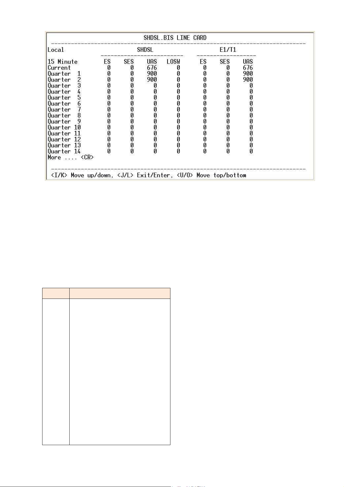
When using Series Interface and Ethernet Interface, there can only display the
SHDSL.bis performance monitor data
While in this display mode the terminal window will not timeout. The 15 minute
display window will display all the performance information for each 15 minute
interval in the current 24 hour period. There are a total of 96 intervals. Press the
ENTER key to display the next page of intervals. To exit the window, press
CTRL-C and then ENTER.
Quarter display on each page:
Page
1
2
3
4
5
6
7
Current and 1 to 14
quarter
Current and 15 to 28
quarter
Current and 29 to 42
quarter
Current and 43 to 56
Time display
quarter
Current and 57 to 70
quarter
Current and 71 to 84
quarter
Current and 85 to 96
quarter
75
Page 76
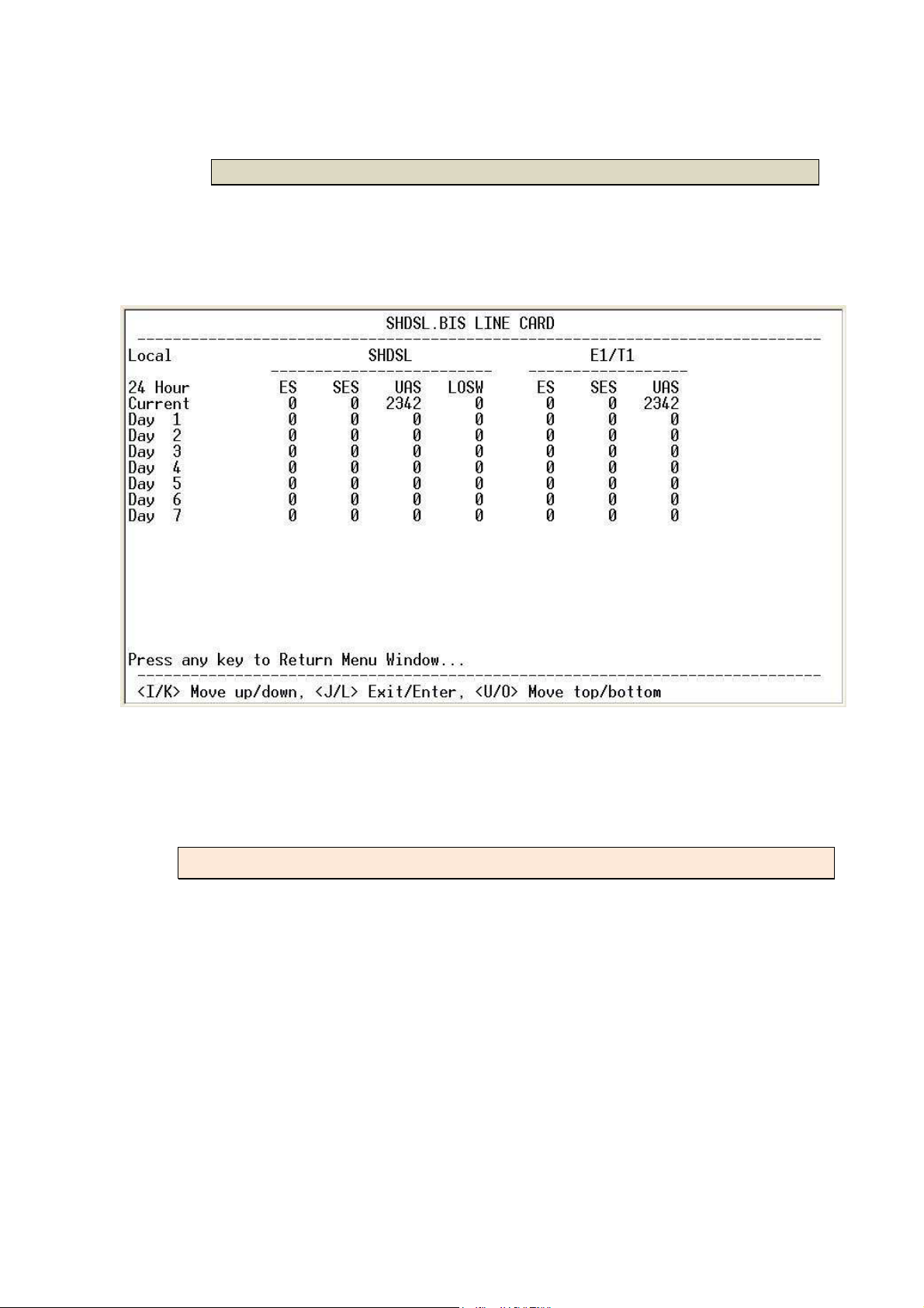
3.7.4.2 24 hours interval
The performance monitor is capable of storing and retrieving performance
information for each 24 hour interval, up to 7 days. The following screen shows
the SHDSL.bis and E1 performance monitored over 7 days.
When using Series Interface and Ethernet Interface, there can only display the
SHDSL.bis performance monitor data
Press any key to leave this menu and go back to the Status Display menu.
3.7.5 Clear
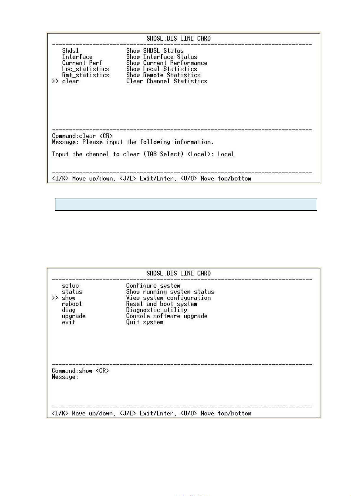
From the Status Display menu, use the down arrow key to select the clear
channel statistics menu item. You may clear the performance statistics for
either Local or Remote side B. After selecting the channel, the data will be
cleared with no further warning.
76
Page 77
3.8 Show
The following is an example of the "Show" menu command. Use the down
menu key "K" or down cursor key and place the cursor on the "show"
command.
With the cursor on the "show" command, press the right cursor key, "J" key or
press ENTER to go to the next sub menu. The following screen will display:
77
Page 78

78
Page 79
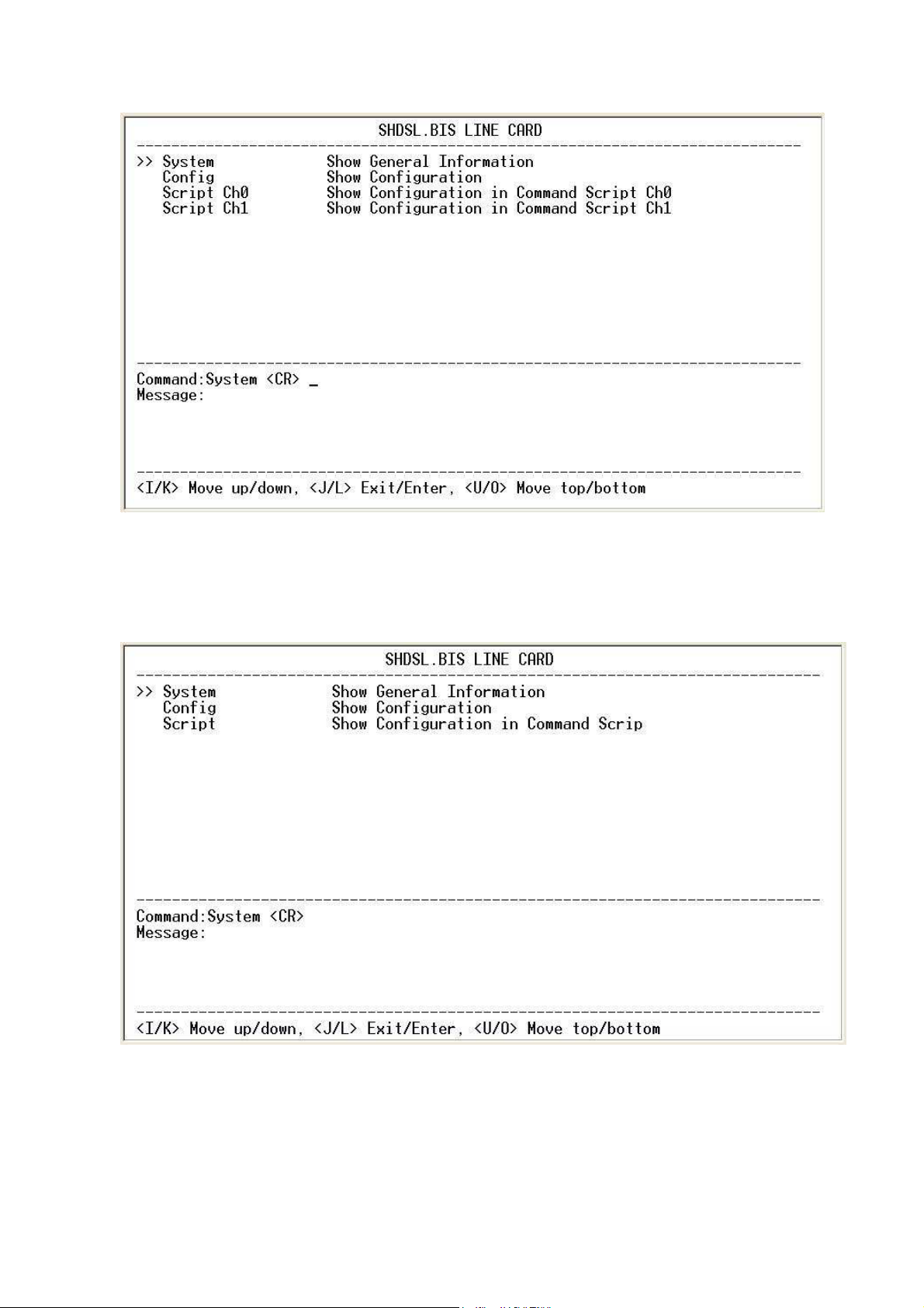
For two wires mode:
Script Ch0 and script Ch1 are meaning channel A and channel B by using
script format.
For four wires mode:
79
Page 80
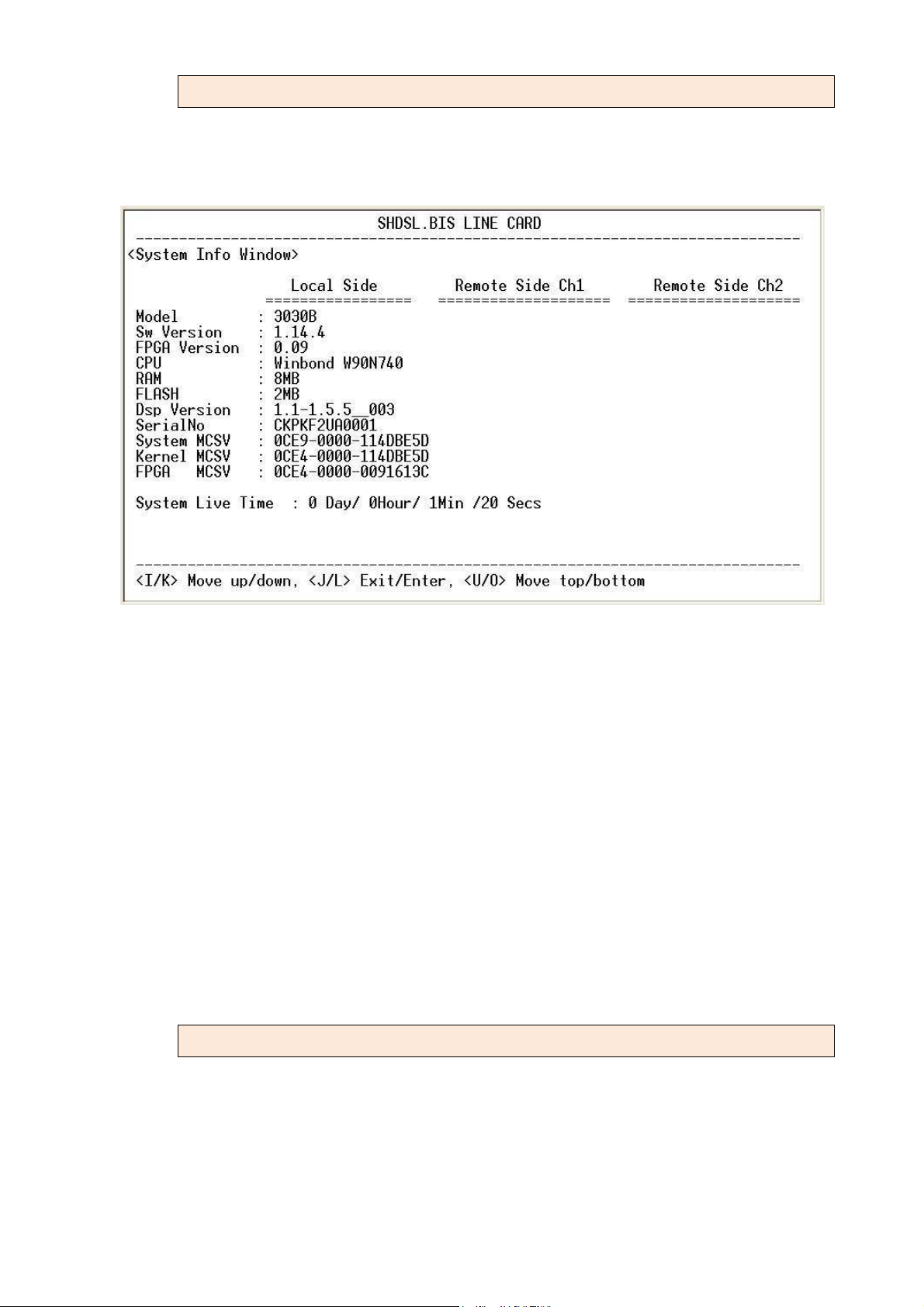
3.8.1 System
Our cursor is already on the "show system" command, so press ENTER and the
following screen will display the general system information.
Most of the information on this screen is either self explanatory or it is simply
irrelevant for the end user. However, two items, the Kernel and FPGA (Field
Programmable Gate Array) version will give the software and hardware
versions respectively of the line card. These are important to know in case new
firmware becomes available in the future to add extra functions of to fix
unknown bugs from the original manufactured equipment. Please make note
of the Kernel MCSV and FPGA MCSV items in the above screen. These show
the Kernel and FPGA versions as follows:
114 means version 1.14
009 means version 0.09
Upgrading the line cards is done through the terminal connection with the
Xmodem protocol. The upgrade procedure will be explained in detail later in
this manual.
3.8.2 Config
It can display the all configuration value of this line card. The following show all
models’ configuration page and their default values. When using 2 wire mode,
there have two channel’s data been displayed as the page.
80
Page 81
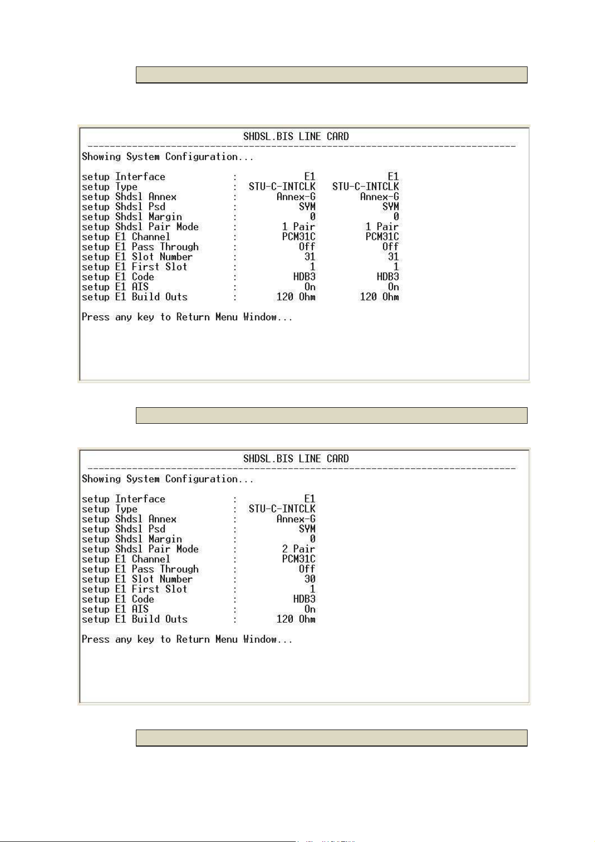
3.8.2.1 E1 interface 2 wire mode
3.8.2.2 E1 interface 4 wire mode
3.8.2.3 Series interface 2 wire mode
81
Page 82
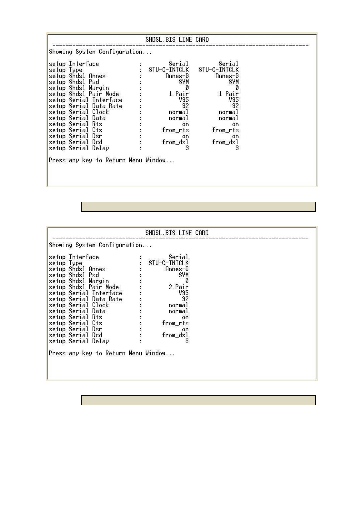
3.8.2.4 Series interface 4 wire mode
3.8.2.5 Ethernet interface 2 wire mode
82
Page 83

3.8.2.6 Ethernet interface 4 wire mode
83
Page 84
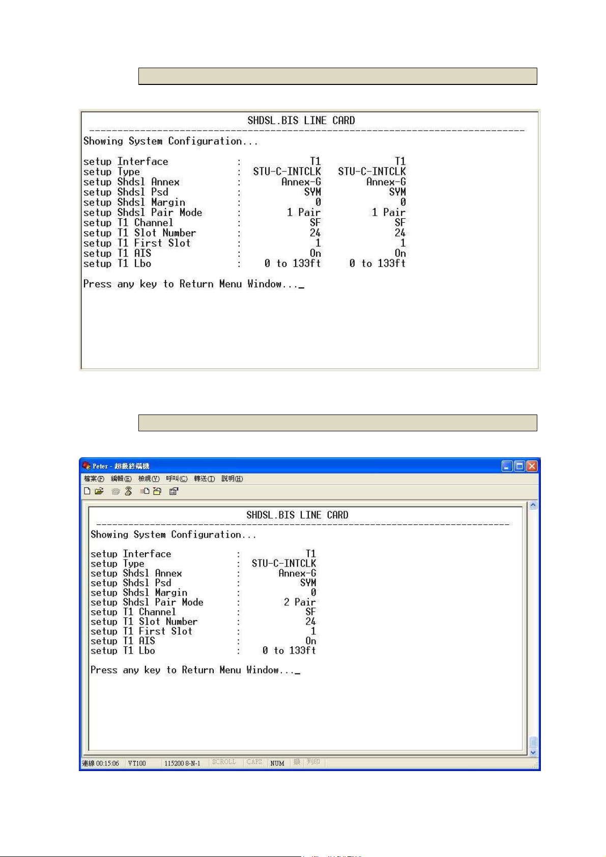
3.8.2.7 T1 interface 2 wire mode
3.8.2.8 T1 interface 4 wire mode
84
Page 85
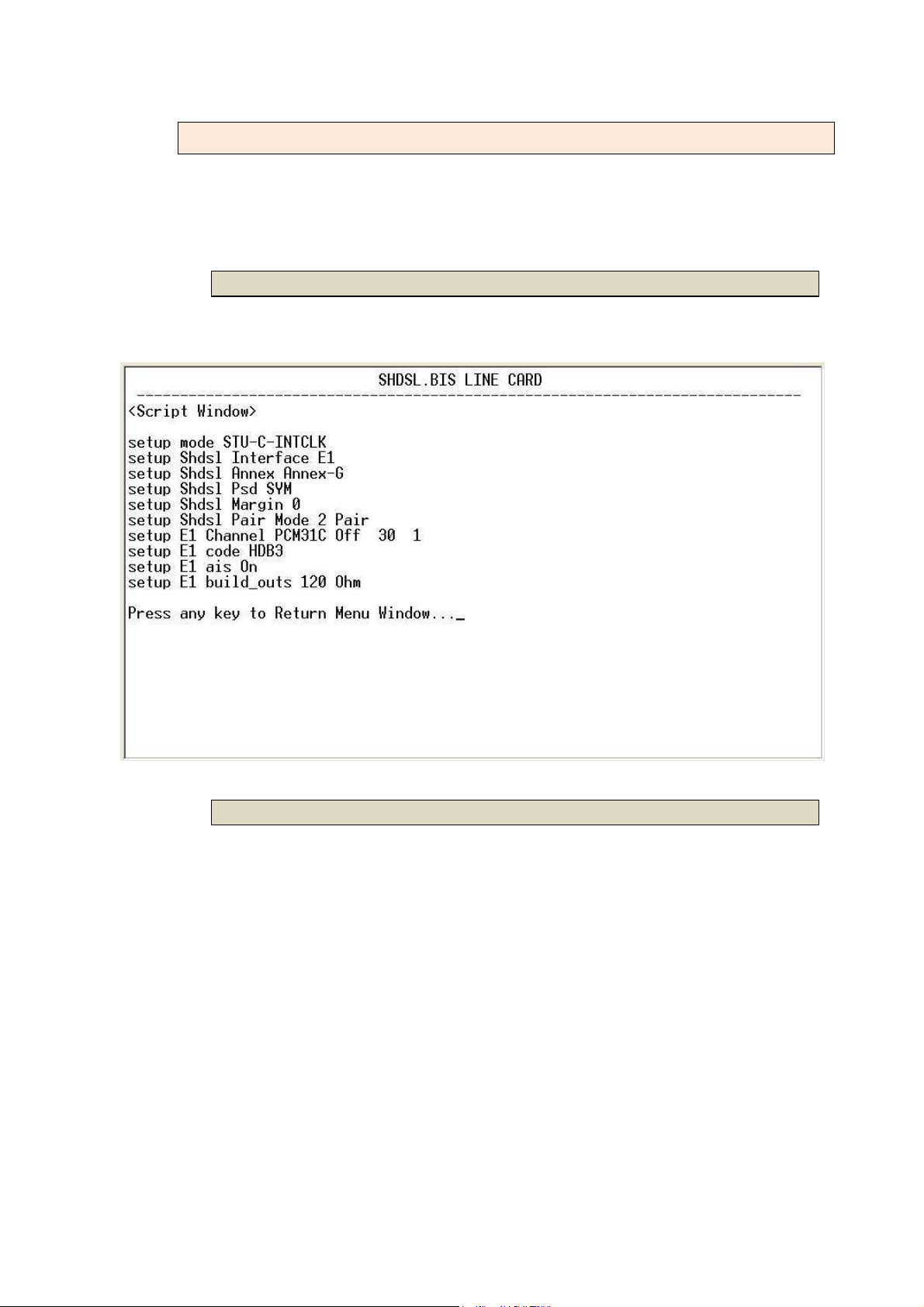
3.8.3 Script
It can display the all configuration value of this line card with using Script
command format.
3.8.3.1 E1 interface
For E1 interface model:
3.8.3.2 Serial interface
For Serial interface model:
85
Page 86
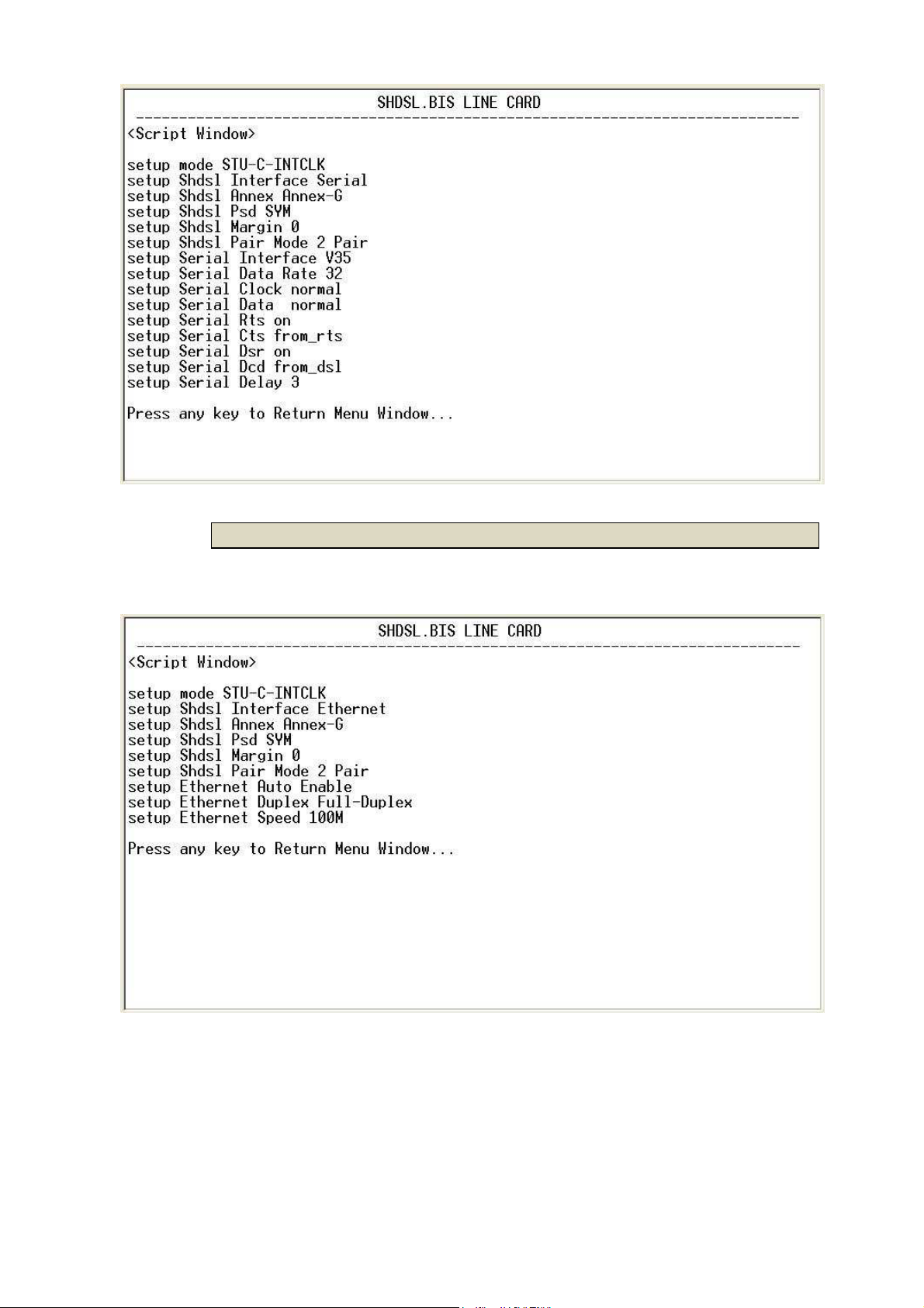
3.8.3.3 Ethernet interface
For Ethernet interface model:
86
Page 87
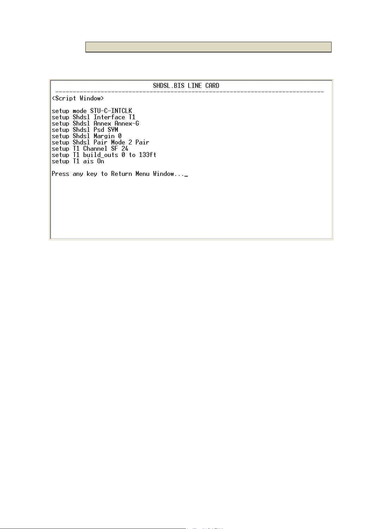
3.8.3.4 T1 interface
For T1 interface model:
87
Page 88
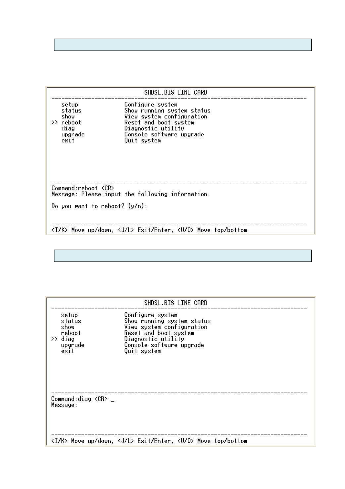
3.9 Reboot
This is a very basic function that needs no further explanation, select it and the
line card will reboot after confirming.
3.10 Diag
The diagnostics features of the line card include loop back and Bit Error Rate
functions. From the main menu move the cursor down to the 'diag' option.
88
Page 89
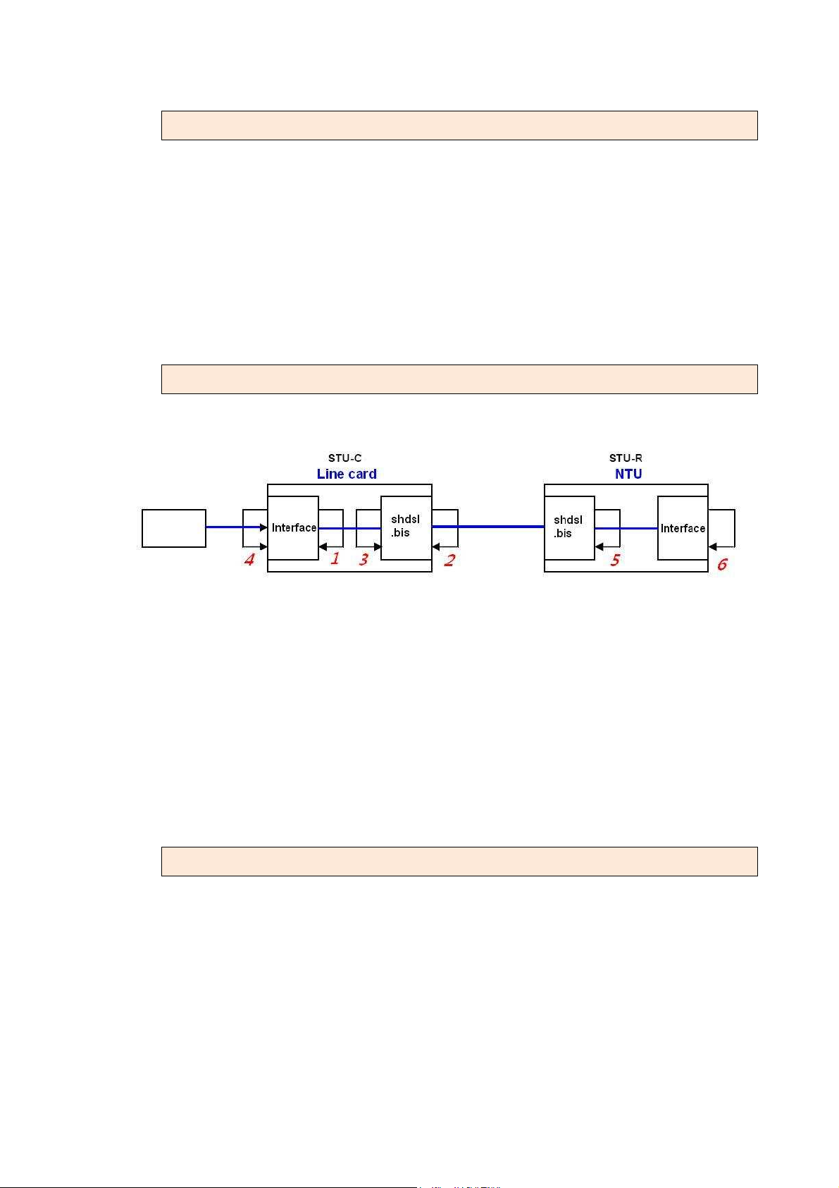
3.10.1 Select Loop back type
The loop back types supported include local digital, local, remote line, remote
payload, far end line, and far end payload loop backs. When line card
doesn’t connect to other remote side NTU,
There can display and supported include local digital, local, remote line,
remote payload loop backs.
3.10.2 Loop back types defined
1 Local Digital Loopback
2 Local Loopback
3 Remote Line Loopback
4 Remote Payload Loopback
5 Far End Line Loopback
6 Far End Payload Loopback
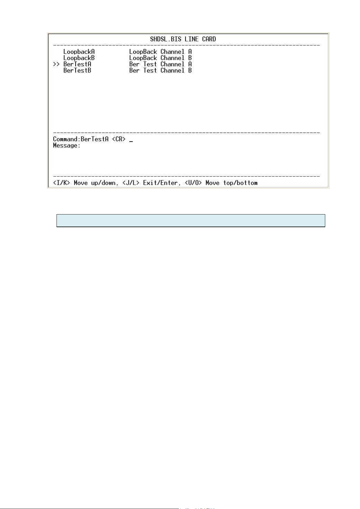
3.10.3 Select BERT pattern
The line card has a built-in Bit Error Rate Test generator that generates a
standard 2047 (211-1) test pattern. When using 2-wire SHDSL.bis configuration,
the generator can be activated for channel A or B from the menu.
89
Page 90
3.11 Upgrade
Occasionally we may release code to upgrade the function of or fix some bug
discovered after our initial production.
The line cards all have the ability to upgrade the code without changing any
components or removing cards. Of course during upgrade and re-flash, the
normal transmissions will be halted, so the upgrade should be done when the
system is taken offline or done during a time of extremely low impact to the
customer's line (like in the middle of the night). The upgrade process uses the
Xmodem protocol via the line card's serial console port.
90
Page 91

3.11.1 Upgrade the FPGA
The hardware in the line card can be upgrade if new functions are added at a
later time. The line card incorporates a Field Programmable Gate Array to
control the line card's logic. To upgrade the code, choose the 'Upgrade FPGA
code' option from the menu.
Press Enter to enable the reception of Xmodem protocol.
91
Page 92
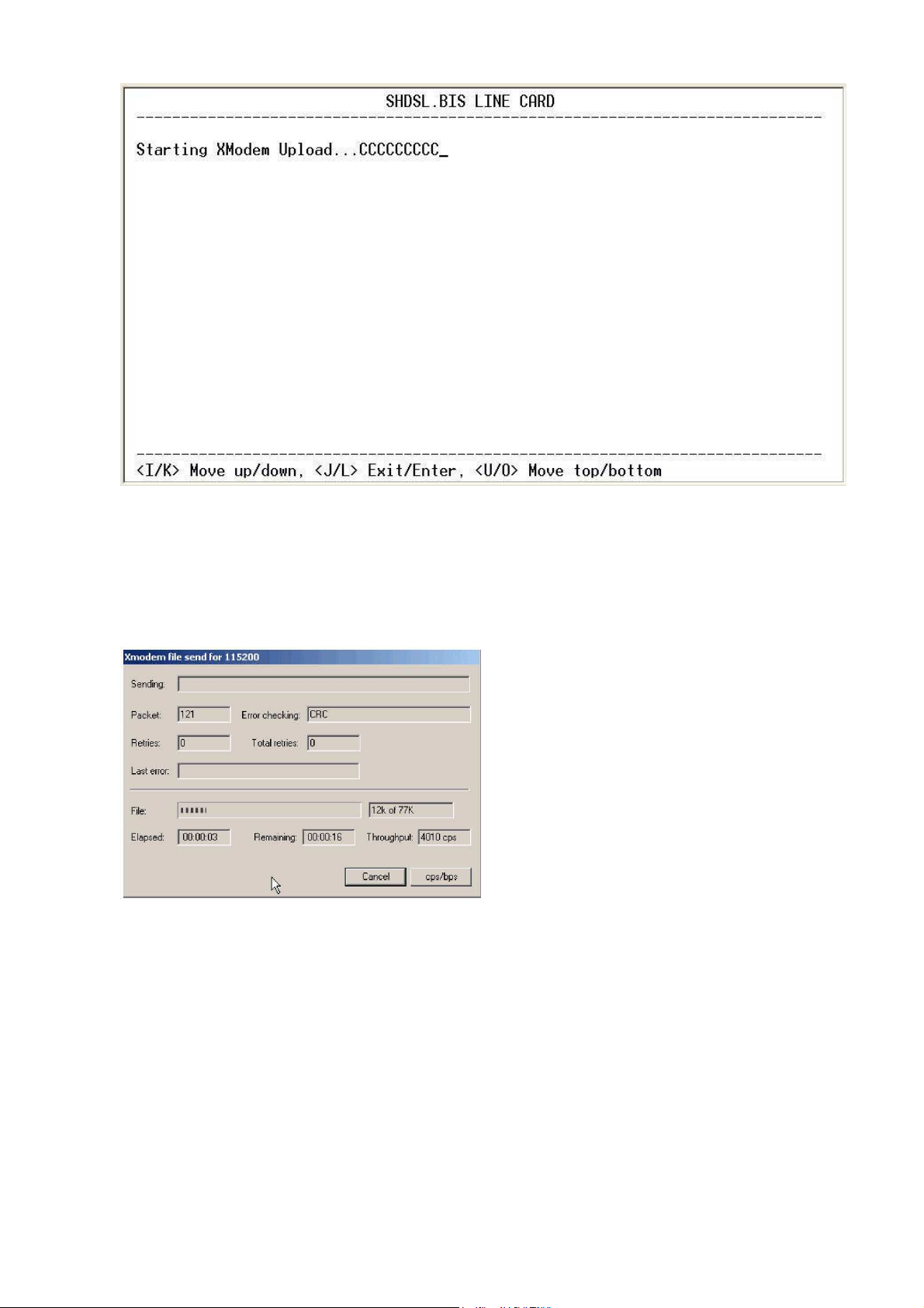
If you are using the HyperTerminal program in Windows, select the "Transfer"
pull down menu and select "Send File".
Now browse to the location of the binary file and select the FPGA upgrade file.
Make sure the sending protocol is Xmodem and send the file.
The binary file is uploaded to the RAM in the line card with CRC error checking
provided by the Xmodem protocol.
Once the upload is complete, all that is required is to make the final
confirmation to erase and re-write the flash with the new binary code.
WARNING!: Do not allow any interruption of power during the erase and
re-write
operation or the Flash will be left in an unknown state and the line card will no
longer be able
92
Page 93
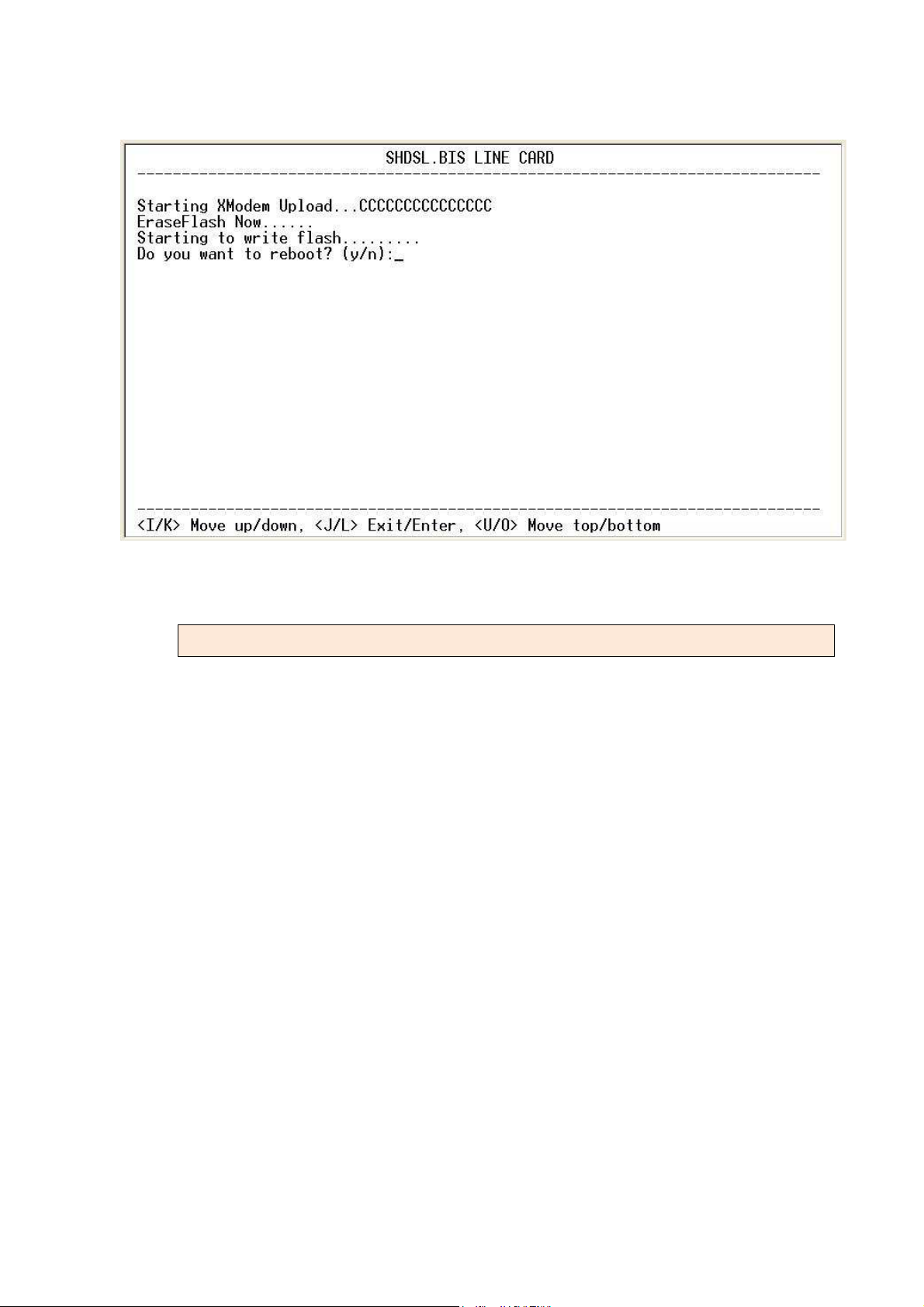
to function. The line card must then be returned to the factory for repair.
3.11.2 Upgrade the Kernel
To upgrade the kernel (software) follow exactly the same procedure and
select 'kernel' from the upgrade menu. Use the binary file for the kernel to send
from the HyperTerminal window.
93
Page 94
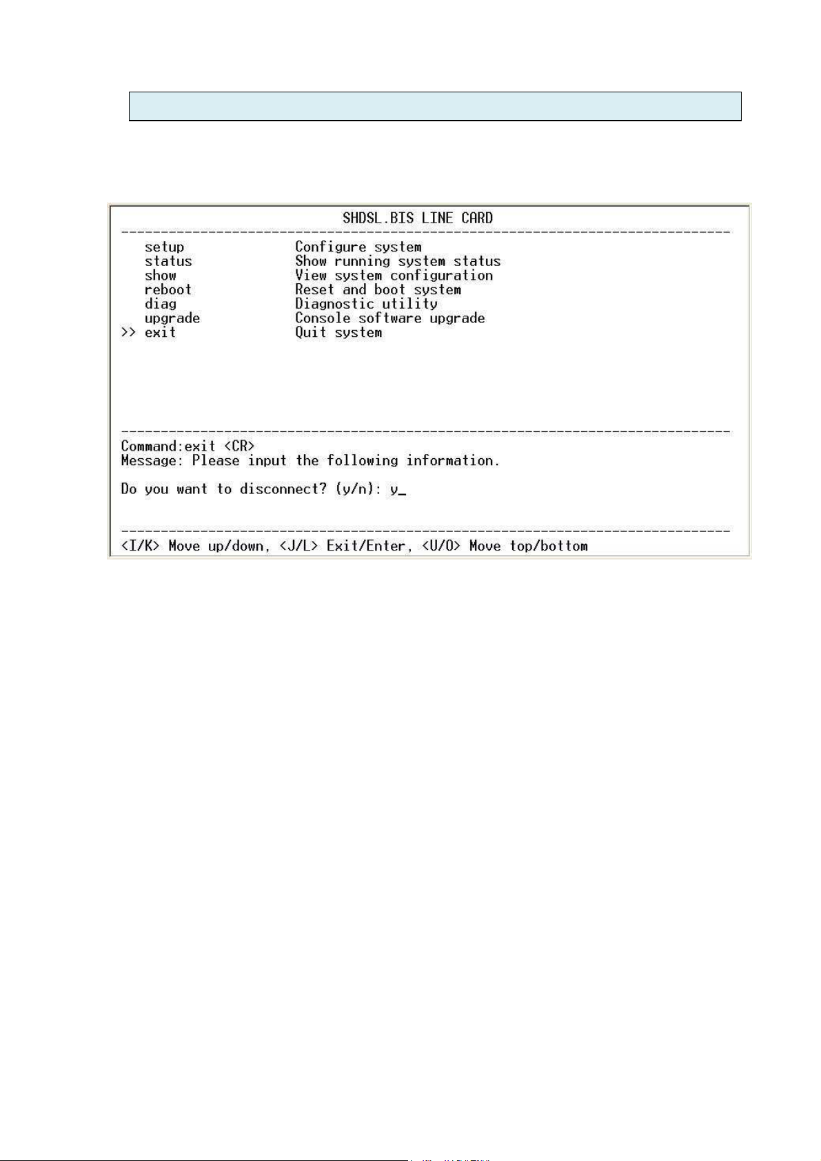
3.12 Exit
To exit the console configuration mode, cursor down to 'exit' and press Enter.
Answer y(es) to confirm.
94
Page 95

4
Network Management System (NMS)
4.1 Overview
This chapter describes the Network Management System (NMS) used to
access statistical, configuration and management through a Hyper
Terminal/Telnet/Web Browser with real time monitoring & trap alarm in window
graphic mode
CTC Union develops a perfect solution for the network managements. The
intelligent NMS provides the support that the network manager needs. It
consists of three modes:
1. Hype Terminal mode: Configuration by local RS-232 serial Console port of
SNMP card
2. Telnet mode: Configuration by 10/100 Ethernet LAN port of SNMP card
3. Web-based mode: Configuration by 10/100 Ethernet LAN port of SNMP card
CTC Union’s network management systems support various important
functions :
1. Fault management - correlates fault management data from all network
devices, isolates faults and initiates recovery actions
2. Configuration management
3. Performance management
Features
View which type of cards occupy the chassis slots
Full Read/ Write capabilities
Enable/ Disable individual cards or channels
Alarm detection for each card, power module
Cards maintain their configuration even if the Management Module fails
Using Windows GUI (Graphical User Interface)
Configuration settings up or download to/from management PC
Loop-back test capability
Get CPE status of remote NTU side
95
Page 96
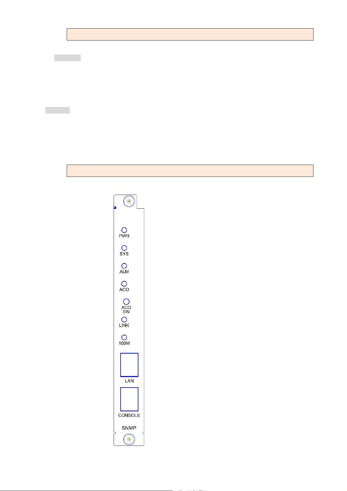
4.1.1 System Requirements
The following are required for use of the NMS:
Hardware:
RJ-45 to DB-9(F) Console cable
RJ-45 to RJ-45 Ethernet Cable
Required for establishing a direct connection from the SNMP card of rack mount shelf to a web
server
Software:
Hyper Terminal
Telnet
Web Browser (IE etc.)
4.1.2 View of front Panel on SNMP card
96
Page 97
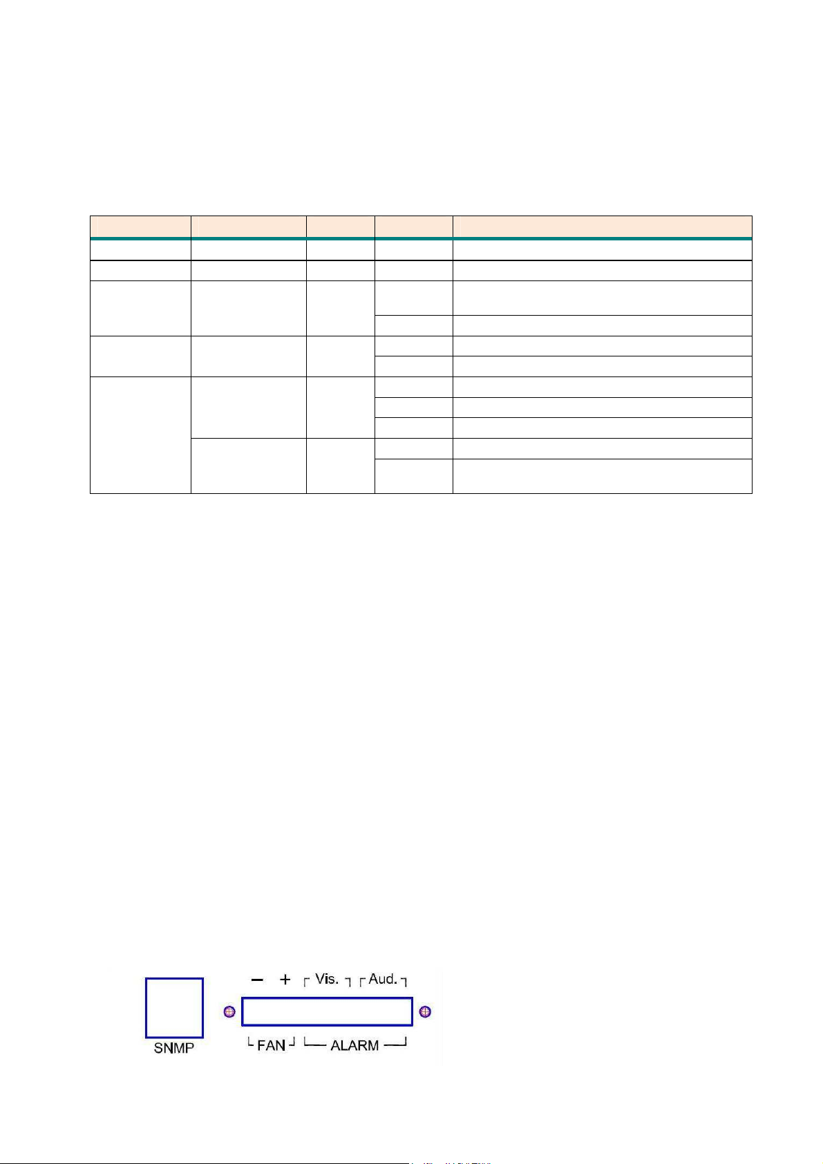
LEDs status of Reset bottom of SNMP card:
Items LEDs Color Active Description
Power PWR Green On Power supply is connected
System SYS Green Flash The system is working
Alarm
Status
ACO
Status
Ethernet
Interface
status
ALM Red
ACO Green
LINK Green
100M Green
On
Off No alarm
On When audible alarm is inactive
Off No audible alarm
On LAN port connected
Blink Transmit or received data over Ethernet
Off LAN port is disconnected
On LAN port connect with 100M NIC
Off
Any failure on line card or power supply
card
LAN port acts in 10M or LAN port is no
connect
[ACO] Alarm Cut-Off
When alarm status is active, audible and visuable alarm output are On. If the
user want to turn off the audio alarm, please press the ACO SW bottom. It will
turn “ACO”LED off and turn audible alarm off.
[Aud.] Audible Alarm Output
If there are alarm triggered and ACO is inactive. It will be turn the audible relay
on, otherwise turn off.
If ACO is active and new alarm is triggered, it will be turn the audible relay on
again. It show that the other alarm status been found.
[Vis.] Visuable Alarm Output
If there are alarm triggered, it will be turn the visuable relay on; otherwise turn
off.
Rear Panel view of SNMP card:
97
Page 98
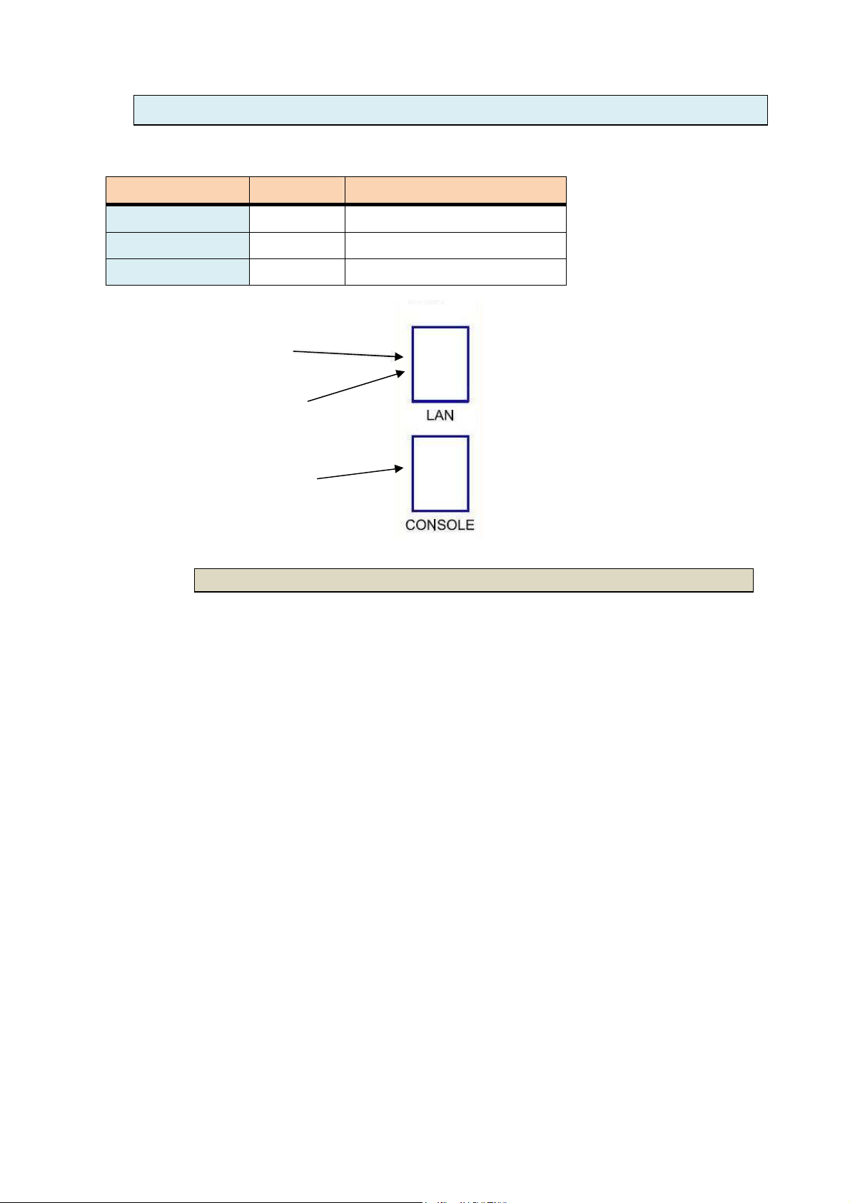
4.2 Operation Mode for SNMP card
User can use one of three operation mode of the following:
Operation Mode Port Usage of Cable
Hyper Terminal Console DB9F to RJ-45 serial Cable
Telnet LAN Ethernet cable
Web-based LAN Ethernet cable
Telnet
Configuration by local RS-232 serial port of SNMP card by Hyper terminal
The console port of SNMP card is a RJ-45 connector labeled Console on the
card face.
The is an RS-232 asynchronous console terminal port designed to facilitate
setup of all parameters through the use of a standard text based terminal or
Web-based
Hyper Terminal
4.2.1.1 Hyper Terminal mode
any terminal emulation program running on a Personal Computer.
You can manage the Line Card locally by connecting the console port to a
PC or workstation with terminal emulation software. After the physical
connection is made, you are ready to configure the SNMP Card. Make sure
you have connected the supplied RS-232 serial cable (DB9F to RJ-45 Plug) to
the console port on the front panel of SNMP Card.
Run a terminal emulation program (such as HyperTerminal) with the following
settings:
Emulation: VT-100 compatible
Band rate: 115200, Data bits: 8, Parity: None, Stop Bits: 1, Flow Control: None
98
Page 99

4.2.1.2 Telnet mode
Configuration by LAN port of SNMP card by Telnet
The Console (Management) port does not have switching capabilities; its main
purpose is to allow a direct PC connection for SNMP and NMS access. A direct
connection with the console port may also be used to access the
management system with Command Line Interface (CLI) via Telnet.
The 10/100 Ethernet management port auto-negotiates speed and duplex
mode; these
Configuration cannot be set on the rack mount shelf. For the best
configuration results, your PC should be set to auto-negotiate speed and
duplex mode as well. If your PC cannot be configured to auto-negotiate,
speed may be set at either 10 Mbps or 100 Mbps but duplex mode must be set
to Half Duplex; a 10/100BaseT Ethernet MGMT connection cannot be made if
your PC is set to Full Duplex.
Using a straight-through or cross over Ethernet cable, connect your PC to the
Ethernet RJ45 management port on the front of the LAN connector of SNMP
card.
The LINK LED will illuminate green to indicate an Ethernet connection has been
established.
4.2.1.3 Web-based mode
Configuration by LAN port of SNMP card by Web browser
The Ethernet cable connection like as above. Configuration is by web browser.
Compatible web browsers include Microsoft Internet Explorer (version 4.0 or
higher) and Netscape Navigator (version 4.0 or higher). NMS is optimized for
use with Internet Explorer.
Use your browser's default settings when running NMS. JavaScript must be
enabled. Set your screen resolution to 1024 x 768 pixels or higher for optimum
viewing of NMS screens.
4.3 Hype Terminal operation mode
Check the connectivity of the RS-232 cable from your computer to the
console port of SNMP card.
Run the terminal emulation program such as Hyper Terminal with the following
setting:
99
Page 100
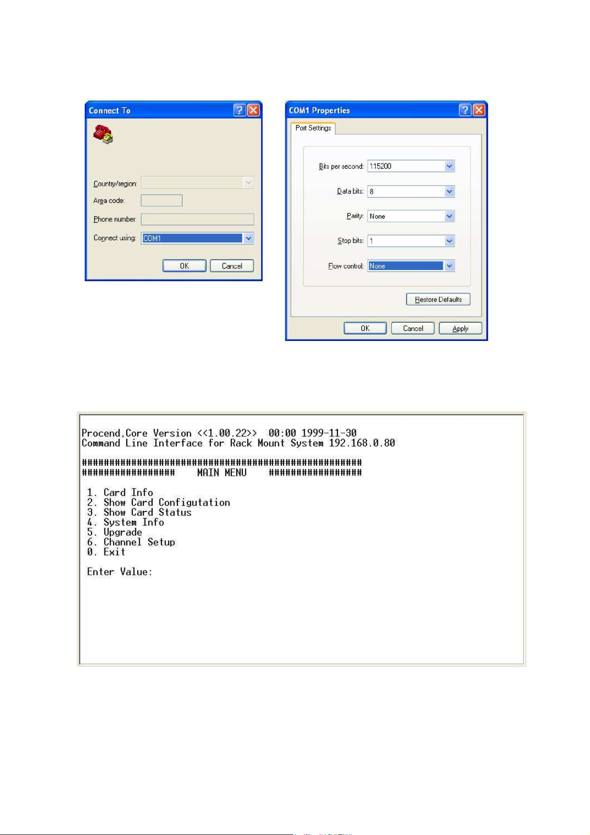
Emulation: VT-100 compatible
Band rate: 115200, Data bits: 8, Parity: None, Stop Bits: 1, Flow Control: None
The main menu :
Their display screen are same as Telnet mode. Please refer to the chapter of Telnet operation mode.
100
 Loading...