

Page 1
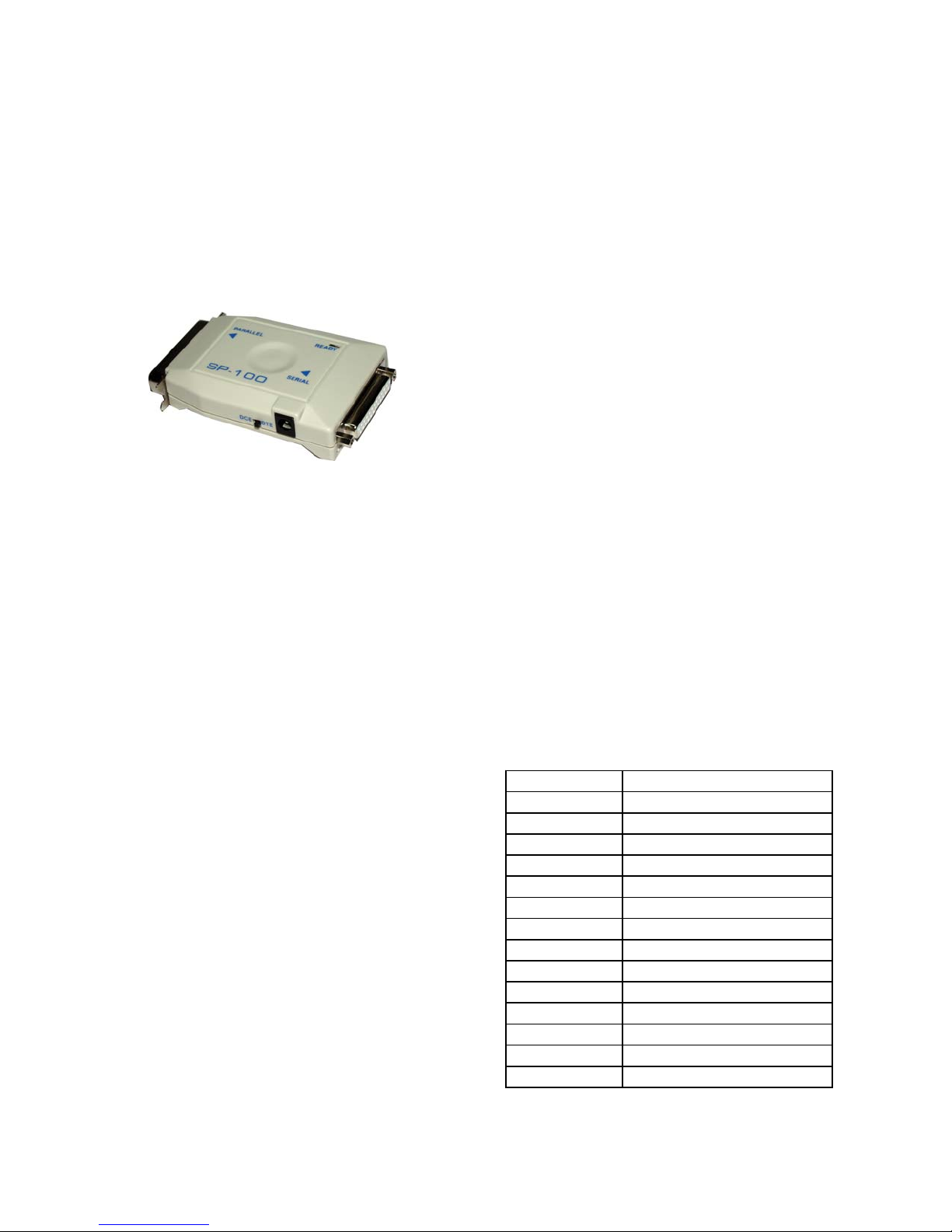
PS-100/SP-100
Parallel to Serial or
Serial to Parallel
Converters
User's Manual
1-3 CONFIGURING THE PS-100/SP-100
1. Gather all the information you can about the
serial port and the parallel port on the host and
peripheral.
2. Power off the devices which you are going
to connect with.
3. Setup the DIP switches on the converter according to the serial information. (transmission
Baud rate, data length, stop bit and parity
check.)
4. Slide the DTE/DCE switch to cooperate with
the serial device. (See Note 2)
5. Connect converter to host and peripheral with
suitable extension cables.
6. Plug in the power plug head of the power
adapter into the power jack of PS-100/SP-100.
7. Turn on all the connected devices. The converter will be ready to work.
1-1 PS-100/SP-100 INTRODUCTION
The PS-100/SP-100 one-way converter is a low
cost converter device. The purpose of the device
is either to convert a parallel (Centronics) interface into a Serial (RS-232C) interface or to convert a Serial interface into a parallel interface. The
main difference between the PS-100 and the SP100 is that the PS-100 converts parallel signal to
serial signal and the SP-100 converts serial signal
to parallel signal.
1-2 Operation
The operation and installation of the PS-100/SP100 are very simple and easy. For the PS-100, the
user only needs a 25-pin to 36-pin cable linked
from DEVICE A parallel port LPT1 (or LPT2) to
PS-100 parallel port, then plug in the PS-100 Serial ports directly to DEVICE B Serial port.Finally
plug in the power adapter plug into the PS-100
power jack. For the SP-100, the user only needs a
25-pin to 25-pin cable linked from DEVICE C
serial port COM1(or COM2) to SP-100's serial
port, then plug the SP-100's parallel port directly
to DEVICE D. Finally, plug in the power adapter
plug into the SP-100 power jack.
PS: After you setup a new DIP SWITCH SETTING, you have to press the "Reset Button."
Then the Ready LED will flash twice, indicating the unit has started running the new settings.
1-4 PS100/SP100 SPECIFICATIONS
Fu nc tion Sp ecificat ion
Power Adapter AC9V, 300mA
Serial Port(DCE) RS-232C, DB25 Female
Pa rallel P ort Cent ron ic s , 36-pin Ma le
Interface Direct ion P→S, S→P
Reset Key Reset Buffer System
Indicator(LED) Display Sys tem Status
Handshake Hardware and Xon-Xoff
Bau d Rate from 300,….,9600, to 19200
Data Bits 7 bits or 8 bits
Parity Bits None, Even or Odd
Driv ing A b ility U p to 9M (30ft )
Enclosure Plastic
Weight 220 grams
Dimen s ion 68W×125L×20H mm
Page 2
DCE DTE Switch
RS-232C Serial Interface definition(DB25)
Pin Name Function Data Direction
TXD Transmit Data DTE→DCE
2
RXD Receive Data DTE←DCE
3
4
5
6
7
8
20
RTS Request to Send DTE→DCE
CTS Clear To Send DT E←DCE
DSR Dat a Set Ready DT E←DCE
GND Ground 0V
DCD Data Carrier Detect DTE←DCE
DT R Dat a T erminal Ready DT E→DCE
Note
1) When the setting for Data Bits is "7" and
parity is none, there are 2 stop bits. In all
other modes the STOP BIT is 1 stop bit.
2) The mode of the serial port of SP-100/
PS-100 is compatible with DTE or DCE
mode. Normal connection to PC with one to
one cable required setting to DCE.
APPENDIX
CENTRONICS INTERFACE SPECIFICATION
Pin No. Name Function
1
2-9 D0-D7 Data Bu s
10
11
12
13
14
15 NC Open
16-17 GND Grou nd
18 NC Open
19-30 GND Grou nd
31 IN IT Initia l Signal (Pu ll up )
32 ERROR Error Sign al (p ull up)
33 GND Ground
34-35 NC Op en
36 SLCT-1 Ground
STB Data Strobe
ACK Data Acknowledge
BUSY Device Busy Signal
PE Paper Empty (Pull Down)
SLCT
AF Auto Feed (Pull up)
Device Select (Pull Down)
AC 9V
200mA
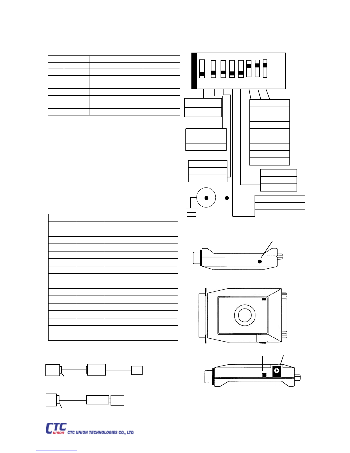
1-5 DIP SWITCH SETTING
PS-100/SP-100 Bottom View
ON DIP
1 2 3 4 5 6 7 8
1. Direct ion
No n
2. Handshake
OFF =H/ W
ON=XON/ XOFF
3. Data BITS
OFF=8
ON=7
¡Ï
6-8 Ba ud Rat e
111→9600
110→19200
101→19200
100→300
011→600
010→1200
001→2400
000→4800
5. Pa rity Type
4. Parity Setting
OFF=DISABLE
ON=DISA BLE
1-6 Outlook Description
Display System Status
PARALLEL
READY
SERIAL
1=ON
0=OFF
OFF=ODD
ON=EVEN
Reset Switch
Application
25pin-to-36pin
A
PC
LPT1 printer port
25 to 25
C
PC
com1 serial port
PS100
SP100
25 to 25
parallel
D
printer
serial
B
printer
ISO 9001
DCE/DTE Slide-sw
DCE
Tel:(886) 2 2659.1021
Fax:(886) 2 2799.1355/ 2 2659.0237
E-mail:[email protected]
http://www.ctcu.com
Power Jack
DTE
 Loading...