

Page 1

PowerStation Flash Memory Replacement
Background
This document describes the procedures for re placing the flash memory on
PowerStations. The P2, P3, and P5 PowerStations come equipped with
flash memory in place of a hard drive. This section describes how to
remove and replace flash memory for these units.
This procedure requires the following tools:
• Slotted head (#2) screwdriver
• Phillips head (#0) screwdriver
• Quarter inch nut driver
Important
Before you begin re moving or r eplacing the flash memory, b e sure to back
up any important data o r Inte ract projec ts on t he exi sting flas h disk. Re fer
to the Interact Project Manager User Guide for details on backing up
Interact projects.
The PowerStation uses special flash memory SIMM modules that
are available from CTC. Using flash memory modules from a
different source will cause unreliable memory storage. Also, CTC
cannot guarantee the integrity of backup operations.
Electrostatic Discharge Precautions
Modern integrated ele ctronic devices, espec ially CPUs and memory chips,
are extremely sensitiv e to electrostatic di scharges (ESD) and fields. Be fore
you disassemble the PowerStation, be sure to follow these simple precautions to protect you and the PowerStation from harm resulting from ESD.
1. To avoid electric s hock, always disconnec t the power f rom the Power Station before you remove the backshell cover or separate the backshell from the front panel. Do not to uch any com ponents of the CPU
card or other cards while the PowerStation is on.
2. Disconnect power before making any hardware configuration changes. The sudden rush of power as you conn ect a jumper or instal l a card
may damage sensitive electronic components.
3. Only handle inter nal components in an ESD-safe l ocation usin g appropriate grounding methods.
• Always ground yo urs el f to remove any static cha rge be fore you
• Be particularly careful not to touch the chip connectors.
Computer Technology Corporation
touch the CPU card.
A3-05197-100
Page 2

PowerStation Flash Memory Replacement
• Keep any card i n its anti -static pa ckaging whe n it is not installe d
in the PowerStation, and place it on a static dissipative mat when
you are working on it.
• Wear a grounding wrist strap for continuous protection.
Disassembling the PowerStation
If you have read and underst and the ESD safety prec autions, you are ready
to disassemble the PowerStation. Follow these steps to disassemble the
unit:
Important
1. Turn of f power to the unit.
2. Disconnect the unit from the power source.
3. Remove the unit from its enclos ure, if installed.
4. Place the unit on a st atic dissipativ e mat in a location fre e from dirt and
moisture and protec ted against static discharge. You must also wear an
ESD wrist strap connected to a good known earth ground.
5. Place the unit on its displ ay, and re move the sc rews s ecuri ng th e bac k
cover.
6. Remove the back cover from the unit.
As you begin to disassemble the unit, you will encounter several
different screw sizes. When you reassemble the PowerStation, be
sure to replace the same size screw in the same location as the one
that was removed. Failure to do so could result in damage to the unit.
Removing a Flash Memory Module
The flash memory modules are located on the System Support Card
located directly in front of the CPU card as you face the back of the unit.
You can also identify the System Support card as the card with the 9-pin
and 25-pin D-SUB connectors. The System Suppor t ca rd is shown below:
1. Locate the flash SIMM sockets located in the upper left corner of the
2
Computer Technology Corporation
Page 3
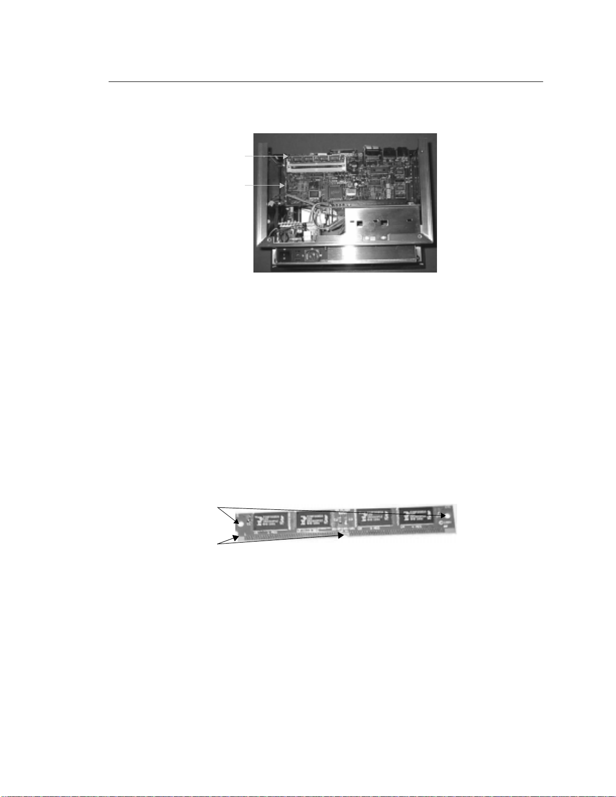
System Support Card.
flash memory
module
PowerStation Flash Memory Replacement
System Support
card
2. Push outward on the socket ejectors. It might be necessary to use a
small screwdriver or the tip of a pen to push on the ejectors.
3. Gently flip the flash memory module upright from the 45-degree angle.
4. Pull the flash memory module outward to remove. Place the flash
memory module on an anti-static surface.
Installing a Flash Memory Module
The steps to installi ng a flash memory module ar e the reverse of removing
a module. Follow these steps to install a flash memory module:
1. Insert the flash memory mod ule into the socke t w ith the notch on the
memory module to the left. The notch on the memory module aligns
with the ridge on the socket. Refer to the picture below:
abs of SIMM soc k et
fit these holes
ridges of SIMM
socket fits these
notches
2. Gently push the module down to a 45 degree ang le until the tabs on the
socket snap onto th e flash memory modu le. Make s ure the socket ejectors are holding the flash memory module in place.
Computer Technology Corporation
3
Page 4
PowerStation Flash Memory Replacement
g
Setting the Flash Memory Jumpers
Like most PCs, the PowerStation uses jumpers to set add resses and enab le
or disable various fu nctions of the syste m. The PowerStati on has four sets
of jumpers for config uring the serial p orts, touch screen, and f lash memory
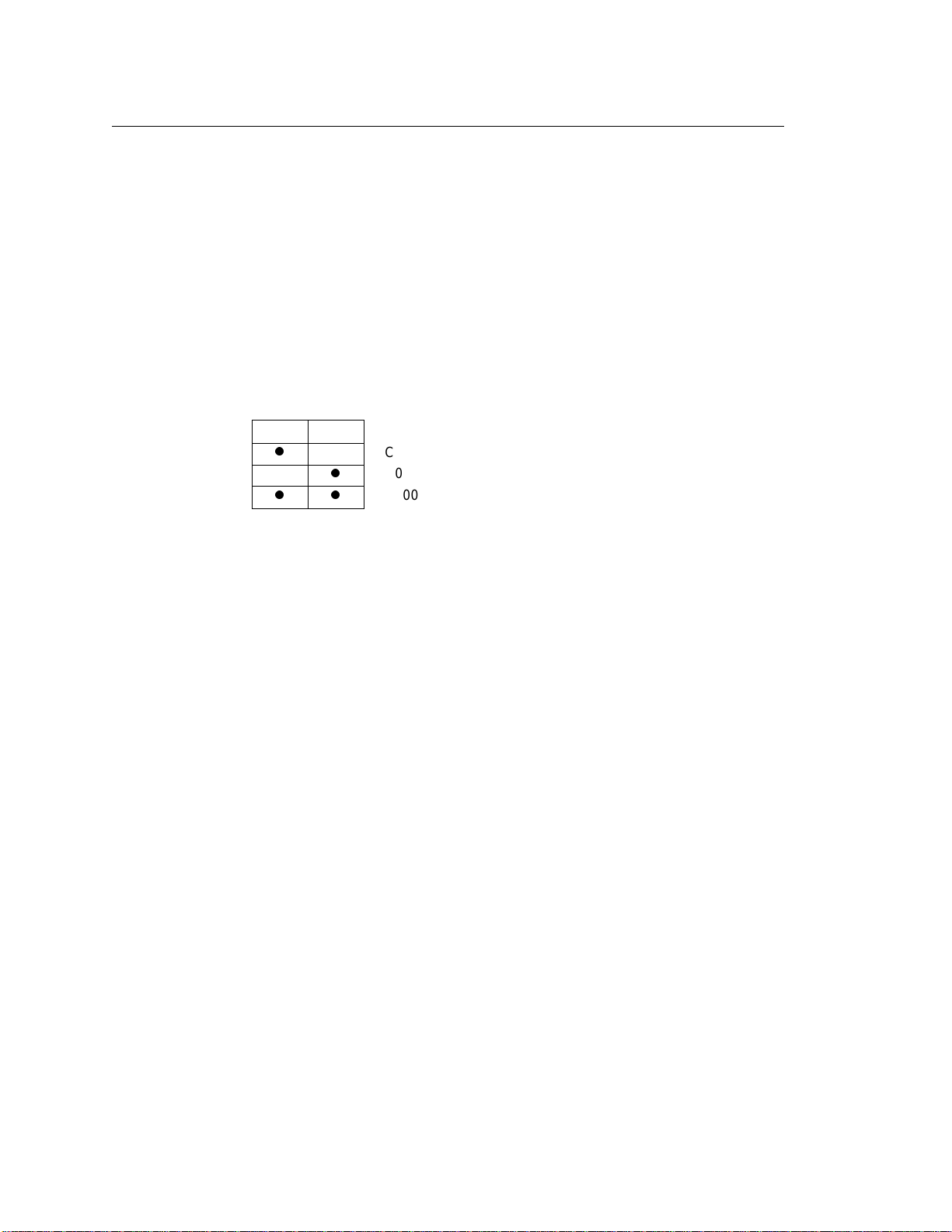
(if available). The jumper settings for the flash memory are shown below.
JP5
This set of jump ers is onl y availa ble on u nits with flash m emory. Thi s
set of jumpers controls where the flash memory appears in memory.
The flash memory uses a 12 Kbyte region of memory starting at the
specified address.
AB
z
z
zz
C8000
D0000
D8000
Starting address of mapped
(used) re
Reassembling the PowerStation
ion
Follow these steps to reassemble the unit.
Important
When you reassemble the PowerStation, be sure to replace the same
size screw in the same location as the on e that was removed. Failure
to do so could result in damage to the unit.
1. Replace the back cover, and tighten the four screws.
2. Reinstall the unit in its enclosure, if previously installed.
3. Restore power to the un it by pluggin g the p ower cord into th e back o f
the unit.
Formatting the Flash Memory
PowerStations equipped with flash memory include a setup utility for
formatting the flash memory. If the flash memor y becomes corrupted or
you install new fl ash memory, you must f ormat the flash memory using the
4
Computer Technology Corporation
Page 5

PowerStation Flash Memory Replacement
flash setup disk. This format procedure will erase all data on the module.
Important
DO NOT use the PowerStation's DOS Format command to format
the flash memory.
1. Insert the flash setup disk into the PowerStation’s floppy drive.
2. Power up the PowerStation.
3. Select option 2 from the Startup Menu, and press Enter to begin the
flash memory test.
Warning
The flash memory test erases the flash memory prior to testing the
capabilities of the flash memory. Be sure to back up any important
data stored on the module before you begin the flash memory test.
4. Press <Y> to continue with the flash memory test when the warning
message appears.
5. Press any key to reboot the PowerStation when the test is complete.
6. Select option 1 from the Startup Menu, and press Enter to format the
flash memory and make it bootable. The set up uti li ty copi es t he most
common DOS commands onto the flash memory.
7. When the flash memory preparati on is complet e, remove the fl ash setup disk. Failure to remove the disk will restart the cycle when you reboot the PowerStation.
8. Press any key to reboot the PowerSt ation. The flas h memory becomes
drive C.
Note
Computer Technology Corporation
The above procedure does not install the shell. The shell must be
installed using the shell installation disk.
5
Page 6

PowerStation Flash Memory Replacement
6
Computer Technology Corporation
 Loading...