

Page 1

NVR
Network Video Reco rder
Page 2

Page 3

LEGAL
The information in this publication has been carefully checked and is believed to be entirely accurate at
the time of publication. CTC Union Technologies assumes no responsibility, however, for possible errors
or omissions, or for any consequences resulting from the use of the information contained herein. CTC
Union Technologies reserves the right to make changes in its products or product specifications with
the intent to improve function or design at any time and without notice and is not required to update
this documentation to reflect such changes.
CTC Union Technologies makes no warranty, representation, or guarantee regarding the suitability of
its products for any particular purpose, nor does CTC Union assume any liability arising out of the
application or use of any product and specifically disclaims any and all liability, including without
limitation any consequential or incidental damages.
CTC Union products are not designed, intended, or authorized for use in systems or applications
intended to support or sustain life, or for any other application in which the failure of the product could
create a situation where personal injury or death may occur. Should the Buyer purchase or use a CTC
Union product for any such unintended or unauthorized application, the Buyer shall indemnify and hold
CTC Union Technologies and its officers, employees, subsidiaries, affiliates, and distributors harmless
against all claims, costs, damages, expenses, and reasonable attorney fees arising out of, either directly
or indirectly, any claim of personal injury or death that may be associated with such unintended or
unauthorized use, even if such claim alleges that CTC Union Technologies was negligent regarding the
design or manufacture of said product.
TRADEMARKS:
Microsoft is a registered trademark of Microsoft Corp.
HyperTerminal™ is a registered trademark of Hilgraeve Inc.
WARNING:
This equipment has been tested and found to comply with the limits for a Class A digital device,
pursuant to Part 15 of the FCC Rules. These limits are designed to provide reasonable protection
against harmful interference when the equipment is operated in a commercial environment. This
equipment generates, uses, and can radiate radio frequency energy and if not installed and used in
accordance with the instruction manual may cause harmful interference in which case the user will be
required to correct the interference at his own expense. NOTICE: (1) The changes or modifications not
expressively approved by the party responsible for compliance could void the user's authority to
operate the equipment. (2) Shielded interface cables and AC power cord, if any, must be used in order
to comply with the emission limits.
CISPR PUB.22 Class A COMPLIANCE:
This device complies with EMC directive of the European Community and meets or exceeds the
following technical standard. EN 55022 - Limits and Methods of Measurement of Radio Interference
Characteristics of Information Technology Equipment. This device complies with CISPR Class A.
WARNING:
This is a Class A product. In a domestic environment this product may cause radio interference in which
case the user may be required to take adequate measures.
CE NOTICE:
Marking by the symbol CE indicates compliance of this equipment to the EMC directive of the European
Community. Such marking is indicative that this equipment meets or exceeds the following technical
standards: EN 55022:1994/A1:1995/A2:1997 Class A and EN61000-3-2:1995, EN61000-3-3:1995 and
EN50082-1:1997
Page 4

CTC Union Technologies Co., Ltd.
Far Eastern Vienna Technology Center (Neihu Technology Park)
8F, No. 60, Zhouzi St.
Neihu, Taipei, 114
Taiwan
Phone: +886-2-2659-1021
FAX: +886-2-2799-1355
NVR
Network Video Software User Manual.
User Manual
Version 4.41 July 2012
This document is the current official release manual. Please check CTC Union's website for any updated
manual or contact us by E-mail at [email protected]. Please address any comments for improving this manual
or to point out omissions or errors to [email protected]. Thank you.
2012 CTC Union Technologies Co.,Ltd.
All Rights Reserved
The contents of this docu ment are subject to change without a ny prior not ice.
Page 5

Table of Contents
i
CHAPTER 1. INTRODUCTION .................................................................................................................. 9
1.1 WHAT'S NEW? ............................................................................................................................................. 9
1.2 CTC UNION NVR FEATURE MATRIX .............................................................................................................. 10
1.3 CAMERA SUPPORTING MATRIX ..................................................................................................................... 15
1.4 GETTING STARTED WITHCTC UNION NVR ...................................................................................................... 20
CHAPTER 2. NVR SYSTEM INSTALLATION .............................................................................................. 25
2.1 INTRODUCTION ........................................................................................................................................... 25
2.2 NVR SYSTEM REQUIREMENTS ....................................................................................................................... 25
2.3 SOFTWARE INSTALL ..................................................................................................................................... 25
2.3.1 Server V.S Client ............................................................................................................................... 25
2.3.2 Exploring the CD contents ................................................................................................................ 26
2.3.3 Installing the Software ..................................................................................................................... 27
2.3.4 NVR Client installation ..................................................................................................................... 34
2.4 START NVR SERVICE ................................................................................................................................... 38
CHAPTER 3. VIDEO STREAMING AND CHANNEL SETTING ...................................................................... 41
3.1 SYSTEM REQUIREMENTS .............................................................................................................................. 41
3.2 DOWNLOAD SETUP ..................................................................................................................................... 41
3.3 USING ONLINE LICENSE AUTHORIZATION ........................................................................................................ 42
3.4 STARTING THE SERVICE ................................................................................................................................ 48
3.5 SETUP FOR MULTI-MONITOR ........................................................................................................................ 49
3.5.1 Consoles and Profiles ....................................................................................................................... 49
3.5.2 Multi-monitor ................................................................................................................................... 50
CHAPTER 4. SYSTEM CONFIGURATION ................................................................................................. 51
4.1 LOG-IN FOR FIRST-TIME ................................................................................................................................ 51
4.2 CHANGE ACTIVE LOCALE .............................................................................................................................. 51
4.2.1 Concepts ........................................................................................................................................... 51
4.3 CONFIGURATION VIDEO STORAGE .................................................................................................................. 52
4.3.1 GUI Overview ................................................................................................................................... 52
4.3.2 Storage Space Parameters ............................................................................................................... 52
4.4 ADDING A CHANNEL .................................................................................................................................... 53
4.4.1 Console operation ............................................................................................................................ 53
4.4.2 Adding a channel .............................................................................................................................. 53
4.4.3 Parameters ....................................................................................................................................... 54
4.5 HOW TO ADD RTSP CAMERA? ...................................................................................................................... 54
4.5.1 Instructions ...................................................................................................................................... 54
4.5.2 How to deal with non-standard RTSP port? ..................................................................................... 56
4.6 SETTING VIDEO PARAMETERS ........................................................................................................................ 57
4.6.1 GUI overview .................................................................................................................................... 57
4.6.2 GUI overview .................................................................................................................................... 58
4.7 SCHEDULE CONFIGURATION .......................................................................................................................... 58
4.7.1 GUI overview .................................................................................................................................... 58
4.7.2 Configuration ................................................................................................................................... 59
4.7.3 Weekly (Graphic) Schedule Configuration ....................................................................................... 60
4.7.4 Scheduled Video Configuration........................................................................................................ 61
4.8 PERMISSION CONTROL OVERVIEW .................................................................................................................. 62
4.8.1 Concepts ........................................................................................................................................... 62
4.8.2 Permission Types .............................................................................................................................. 62
4.9 ADDING A USER .......................................................................................................................................... 62
4.9.1 GUI overview .................................................................................................................................... 62
4.10 ADDING A GROUP ..................................................................................................................................... 63
4.10.1 GUI overview .................................................................................................................................. 63
Page 6

Table of Contents
ii
4.11
CREATING MAPS ...................................................................................................................................... 65
4.11.1 Create New Map ........................................................................................................................... 65
4.11.2 GUI overview ................................................................................................................................. 65
4.11.3 Toolbar Functions .......................................................................................................................... 66
4.11.4 Adding Items ................................................................................................................................. 66
4.11.5 Basic Operations ............................................................................................................................ 67
4.11.6 Special operations ......................................................................................................................... 68
4.12 EXTERNAL MAPS ...................................................................................................................................... 68
4.12.1 Create New Map ........................................................................................................................... 68
4.12.2 Toolbar Functions .......................................................................................................................... 69
4.12.3 Basic Operations ............................................................................................................................ 69
4.12.4 Adding Items ................................................................................................................................. 70
4.12.5 Basic Operations of Objects .......................................................................................................... 70
4.12.6 Special operations ......................................................................................................................... 70
4.13 TRIGGER POLICY ...................................................................................................................................... 71
4.13.1 Adding New Trigger Policy ............................................................................................................ 71
4.13.2 Input Configuration ....................................................................................................................... 72
4.13.3 Output Configuration .................................................................................................................... 72
4.13.4 Channel trigger .............................................................................................................................. 72
4.13.5 Schedule trigger ............................................................................................................................ 72
4.13.6 System trigger ............................................................................................................................... 72
4.13.7 Channel control ............................................................................................................................. 73
4.13.8 Email .............................................................................................................................................. 74
4.13.9 Snapshot ........................................................................................................................................ 75
4.13.10 FTP ............................................................................................................................................... 76
4.13.11 Trigger policy logics ..................................................................................................................... 76
4.14 MOBILE PHONE VIDEO STREAMING (3GPP) ................................................................................................. 77
4.14.1 Overview ....................................................................................................................................... 77
4.14.2 How-tos ......................................................................................................................................... 78
4.14.3 Is the 3G video streaming default enabled? ................................................................................. 78
4.14.4 How to enable 3G video streaming? ............................................................................................. 78
4.14.5 Why can't I see 3G video streaming? ............................................................................................ 79
4.14.6 What are the frame-rate or image size of the 3G streaming video? Can they be changed? ....... 80
CHAPTER 5. NVR SYSTEM OPERATION ................................................................................................. 81
5.1 CONSOLE OVERVIEW .................................................................................................................................. 81
5.1.1 GUI Overview................................................................................................................................... 81
5.1.1.1 Layout Control .............................................................................................................................. 81
5.1.1.2 System control .............................................................................................................................. 82
5.1.1.3 User tree ....................................................................................................................................... 82
5.1.1.4 System briefcase viewer ............................................................................................................... 83
5.1.1.5 Pattern tab control ....................................................................................................................... 83
5.1.1.6 Player ............................................................................................................................................ 84
5.1.1.7 Splitter Control ............................................................................................................................. 85
5.2 VIEWING LIVE VIDEO ................................................................................................................................... 85
5.2.1 GUI Overview................................................................................................................................... 85
5.3 DIGITAL PTZ ............................................................................................................................................. 87
5.2.1 Digital Pan-Tile-Zoom ...................................................................................................................... 87
5.4 RENDERING AUDIO ..................................................................................................................................... 88
5.4.1 GUI Overview................................................................................................................................... 88
5.4.2 Audio Icon Explained ....................................................................................................................... 89
5.5 VIEWING PLAYBACK VIDEO ........................................................................................................................... 89
5.5.1 Concept ........................................................................................................................................... 89
5.5.2 Simple toolbar ................................................................................................................................. 89
Page 7

Table of Contents
iii
5.6
USING PLAYBACK TIMELINE ........................................................................................................................... 90
5.6.1 Overview .......................................................................................................................................... 90
5.6.2 Using timeline .................................................................................................................................. 90
5.6.3 Basic operations ............................................................................................................................... 91
5.6.4 Playback ........................................................................................................................................... 91
5.6.5 Timeline modes ................................................................................................................................ 92
5.7 SYNCHRONIZED PLAYBACK ............................................................................................................................ 93
5.8 PTZ .......................................................................................................................................................... 94
5.8.1 Basic operation................................................................................................................................. 94
5.8.2 Presets .............................................................................................................................................. 95
5.8.3 Patrol ................................................................................................................................................ 96
5.9 BUILDING USER TREE ................................................................................................................................... 97
5.10 TAKING SNAPSHOT .................................................................................................................................... 98
5.11 MANAGING LAYOUT PAGES ........................................................................................................................ 98
5.12 TOUR ...................................................................................................................................................... 99
5.13 STORAGE REPORT ................................................................................................................................... 100
5.14 ALARM DIALOG ...................................................................................................................................... 102
5.15 USER CALCULATOR.................................................................................................................................. 104
5.16 VIEWING LOGS ....................................................................................................................................... 107
5.17 EXPORTING FOOTAGE .............................................................................................................................. 108
5.18 HOT KEYS .............................................................................................................................................. 109
5.19 REMOTE LIVE VIEWING............................................................................................................................. 111
5.20 IO PORT ................................................................................................................................................ 112
5.21 PLAYER CONTROL PANEL .......................................................................................................................... 113
CHAPTER 6. INTELLIGENT VIDEO......................................................................................................... 117
6.1 ACTIVATING INTELLIGENT DETECTION ........................................................................................................... 117
6.2 REGION CONFIGURATION ........................................................................................................................... 118
Page 8

Table of Contents
iv
This page left blank intentionally.
Page 9
Chapter 1. Introduction
9
Chapter 1.
Introduction
Thank you for purchasing the NVR surveillance system developed by CTC Union Technologies Company,
Limited. CTC UNION NVR Server ™ is a surveillance system that delivers the most comprehensive security
architecture for enterprise level security operation.
NVR provides cost-effective scalability to support thousands of cameras and sensors.
Its distributed management technology and modular architecture help reduce the total cost of ownership
and streamline security operations for today's enterprise. For a better understanding, please read this
manual before operating the NVR.
1.1 What's New?
1. New & simplified play control
2. Import/Export System Configurations
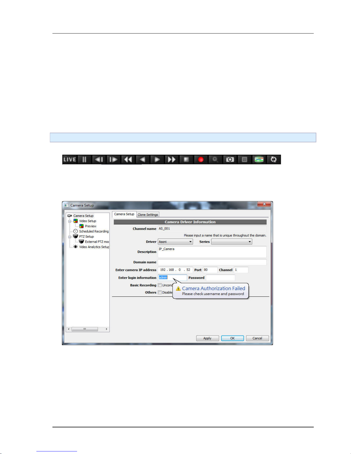
3. Authentication failure message
Page 10
Chapter 1. Introduction
10
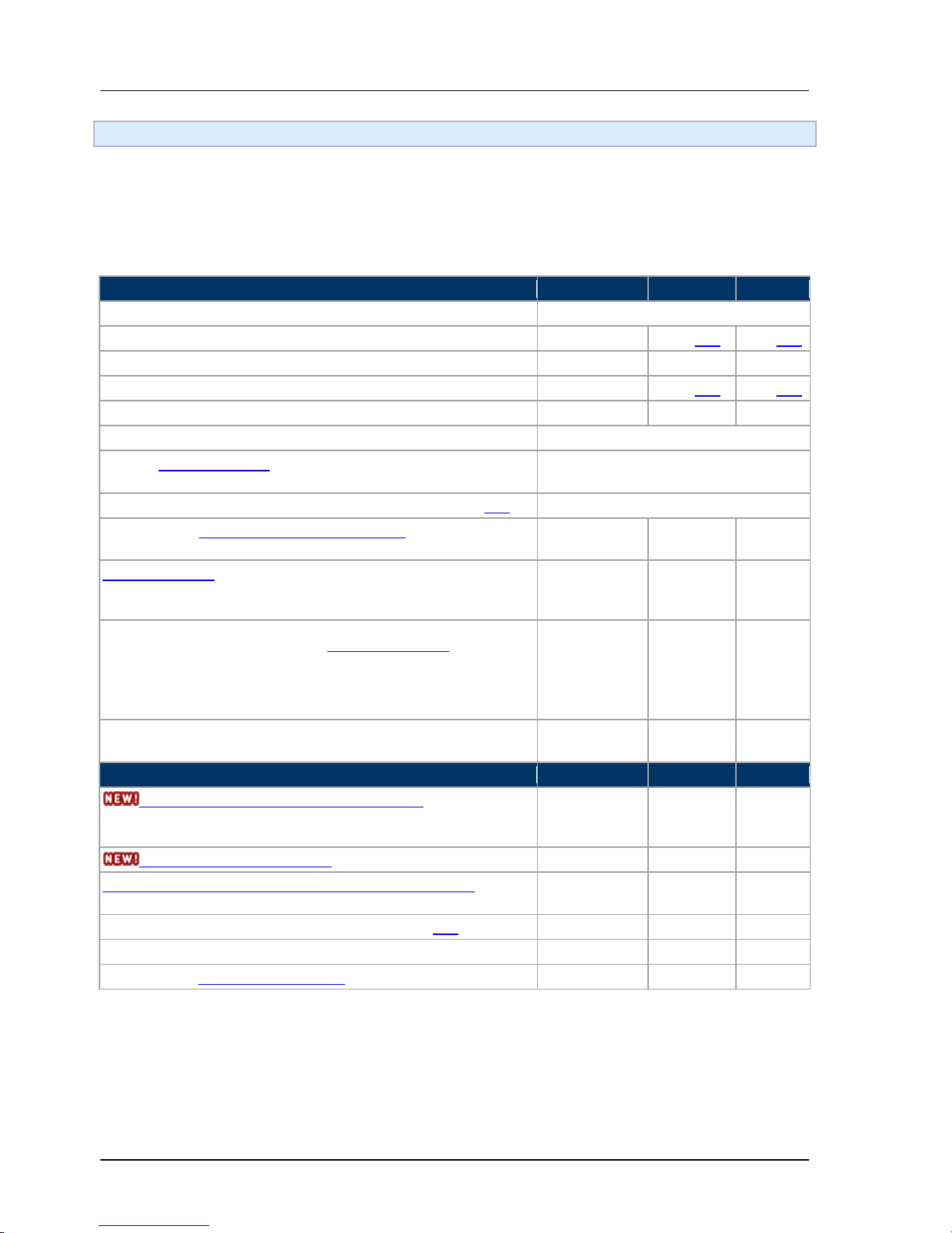
1.2 CTC Union NVR Feature Matrix
Notice :
• NOTE: Terms specified in the document "Copyright Disclaimer " also apply to this document and
content linked by this document.
• Content in this document may change over time and will be changed at the sole discretion of CTC Union.
Function Level 1
Standard
Professional
Intelligent
Maximum concurrent recording channels per server
Depend on actual licensed channels
Maximum number of concurrent login users
3
Max [*3]
Max [*3]
Maximum times of fast playback
32x
512x
512x
Maximum number of concurrent playback sessions per server
4
Max [*3]
Max [*3]
Maximum times of fast playback
32
512
512
Maximum concurrent live view per monitor
25
Support multiple monitor: Maximum number of monitors
supported
6
Maximum number of TCP incoming connection per server [*4]
150
Recording can span into multiple disk volumes. No arbitrary
recording limits.
Single directory
only
v v
Time-bar display (1)Storage space (2)Activity amount(3)Event:
Graphically displays storage space, activity amount, and events
on the time-bar.
Standard and
event mode
only
v v
Sophisticated and comprehensive permission control: Using
groups and hierarchical GUI to represent permissions. Allows
permission control on all or specific channels regarding to live,
playback, operation, and setup
Max 3 users
and 3 groups
v v
Optional display of meta-information, including: timestamp, bps,
Fps, playing status, recording status.
Timestamp only
v vv
Function Level 2
Standard
Professional
Intelligent
Centrally Management Station architecture, providing
management features with integrated security across multiple
NVR servers.
n/a v v
3GPP mobile video streaming
n/a
v
v
Server-side console channel viewing layout configuration. New
user don't have to configure locally after proper configuration.
n/a v v
PTZ advanced operations: preset and preset go-to [*2]
n/a
v
v
MPEG-4/H.264 frame-by-frame backward playback
n/a
v
v
Multi-channel synchronized playback.
n/a
v
v
Page 11
Chapter 1. Introduction
11
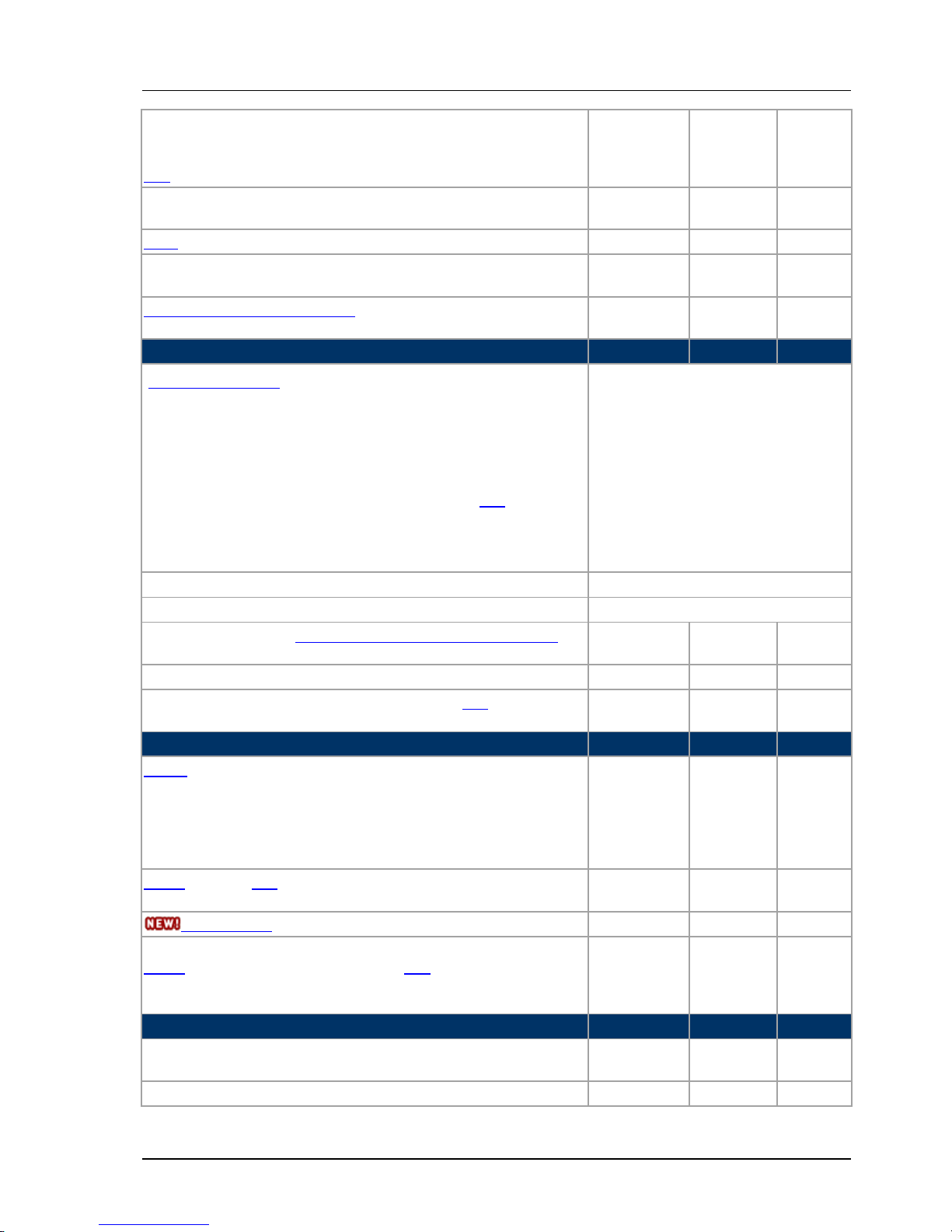
Audio/video synchronized export to AVI file: Export now has the
option to export footage to portable AVI format. Also allow user to
opt to add the raw recorded timestamp overlay as AVI subtitle.
[*1]
n/a v v
Shared logical resource tree. Users can configure an common
arbitrary system tree structures/order with heterogeneous objects.
n/a v v
Tour on console
n/a
v
v
Administrators can assign or retrieve layouts of other remote
consoles
n/a v v
Advanced alarm flow processing: Allow multiple operators to
coordinate and process active and in-progress alarms.
n/a v v
Trigger/Action Features
Standard
Professional
Intelligent
Flexible rule engine for triggering and actions
• System trigger condition for: system start, abnormal
restart, system config change, any channel config change,
any video loss
• Channel trigger condition for: DI/DO on/off[*2], video
loss, recording started, recording stopped, disabled,
enabled, alarm triggered, alarm acknowledged
v
Scheduled trigger condition for: daily, weekly, fixed interval
v
Email notification action (text/html/multilingual)
v
Email notification with snapshot aggregating multiple channels in
split-view
n/a v v
FTP upload snapshot aggregating multiple channels in split-view
n/a
v
v
Channel control action for: recording, output DO[*2], and move to
camera preset
Only support
recording
v v
eMAP/DI/DO Features
Standard
Professional
Intelligent
E-Map: Allows user to edit map and choose arbitrary location and
angle of a camera icon, which reflects camera status in real-time.
Support inter-map linking/navigation/browsing. Allows
viewing/editing in remote site transparently. JPEG and BMP
backgrounds are supported, also with arbitrary resizing and
rotating.
n/a v v
DI/DO on E-Map[*2], reflecting real-time status and provides direct
GUI control. Support several predefined stereo-type icons.
n/a v v
External-map integration (including Google Map)
n/a
v
v
DI/DO on User-tree in arbitrary position[*2], reflecting real-time
status and provide direct GUI control.
Status visible
on standard
tree. No DO
control.
v v
Intelligent Video Content Analysis Features
Standard
Professional
Intelligent
Software-based motion detection. Allows multiple polygon
detection regions.
n/a v v
Tamper detection.
n/a
v
v
Page 12

Chapter 1. Introduction
12
Double-tripwire directional object counting.
n/a
n/a
v
Missing object and foreign object alarm/detection.
n/a
n/a
v
Double-tripwire alarm
n/a
n/a
v
Intelligent video statistics report. View counting in various scale (per
minute, per hour, per day)
n/a n/a v
Basic Features
Standard
Professional
Intelligent
Architectural advantages:
• Disk-access optimized to reduce read/write time. Designed to
handle huge multi-mega pixel data streams and concurrent
number of playback clients.
• Allows the viewing frame-rate to be different from the
actual/recorded frame-rate, and automatically detects
available computing resource.
• Support multi-core processors to boost your system
performance.
• Remote control through Internet Explorer. Identical user-
interface with local interface. (Can opt to install client
software)
• Audio-video synchronized recording and playback
• Most configuration change can take effect immediately
without having to restart system, as well as the change can be
opted to revert to previous state.
• Support many brands of network cameras simultaneously
existing in the system. Also support any RTSP-based video
source. Support M-JPEG, MPEG-4, H.264 and various audio
codec.
v
Basic video player features:
• Seamless integration of live and playback interface. Live and
playback is tightly integrated. User can instantly play
backwardly from live.
• Digital PTZ on both live and playback mode.
• Snapshot JPEG
• PTZ basic operations: on-screen Pan-Tilt-Zoom[*2]
v
Page 13

Chapter 1. Introduction
13
Local/Remote console GUI features:
• Fully multilingual enabled.
• Provides persistent per-user settings of multi-page channel
viewing layout.
• Provide options to remember password and automatic login.
• Provide shortcut script to automatic connect to specified
remote host.
• Automatically and continuously attempt to reconnect upon
connection failure.
• Alarm window flashing. Can opt to switch to 1x1 (popup)
• Full-screen viewing. Can opt to lock keyboard/mouse.
• System events/viewer: System start, configuration change, or
camera alarms.
v
Recording mode:
• Flexible scheduled recording and weekly graphical interface.
• Simple alarm functions. Configurable pre-alarm recording
buffer to support at least 30 seconds.
• Event recording: Allows configuration of event-triggered
recording. Also allows configuration of pre-record and postrecord periods.
• Motion detection: Visually configure motion detection regions
and visually verifies configuration result. [*2]
v
Engine program features:
• Run as Windows service. Engine can be configured to auto-
start recording even without user login nor any GUI activated.
• Prevent non-administrative Windows users from shutting
down the engine.
• Software watchdog. Automatically restart service upon
unknown failure.
• Embedded web server. Don't need to install additional web
server.
v
Export footage (XGV format):
• Export options: Single channel to single file, single channel to
multi-file (size spanned), multi-channel to single file
(combined), multi-channel to multi-file (channel combined, file
spanned).
• Efficient IO with resume able (from interrupt, if any) footage
download transfer over network.
• Single file can contain video of multiple channels.
• Exported file can be appended multiple times later.
v
Page 14

Chapter 1. Introduction
14
Activity analysis and statistics: Records activity (including motion detection) into
a scalar value to indicate the amount of activity occurred at a certain period of
time. This allows user to quickly identify the time of interest to view.
v
Multiple configuration sets for each channel. A configuration set of a channel
specifies channel-specific parameters, such as FPS, quality, etc. A configuration
set can also be "inherited" from other configuration set. The system can be
configured to use different configuration set at different schedule or condition.
v
Storage report:
• Provides a comprehensive report about the recorded storage in
various scales (day, hour, minute).
• Also displays the storage space, statistics of activity, and related
events side-by-side in real-time. This allow user to quickly identify
storage bottleneck and the location of meaningful data
v
User calculator tool:
• Storage space calculator: Provides easy-to-use tool to let user
calculate the required video storage space
• Calculator of field-of-view, resolution for camera lenses: Provides
easy-to-use tool to let user calculate what types of lenses to choose by
computing field-of-view, shooting distance, visual coverage, and
resolution.
v
Remarks
[*1] Not all codec are supported. For more information please refer to here
[*2] Only some selected drivers (hardware models) are supported. For more information
please refer to here
[*3] "Max" means the system places no arbitrary limitation. However the actual limitation
may come from other limiting factors such as server CPU, network, disk I/O throughput, or
memory resource.
[*4] Number of TCP connection required are calculated as follows: If N is the number of
active user sessions, and M is the total number of video connection requested, then the
required number of TCP connection is N*3 + M. Local connection is also accounted. Using
connections exceeding this number is not recommended, as connection request will simply
not be accepted by server.
Page 15

Chapter 1. Introduction
15
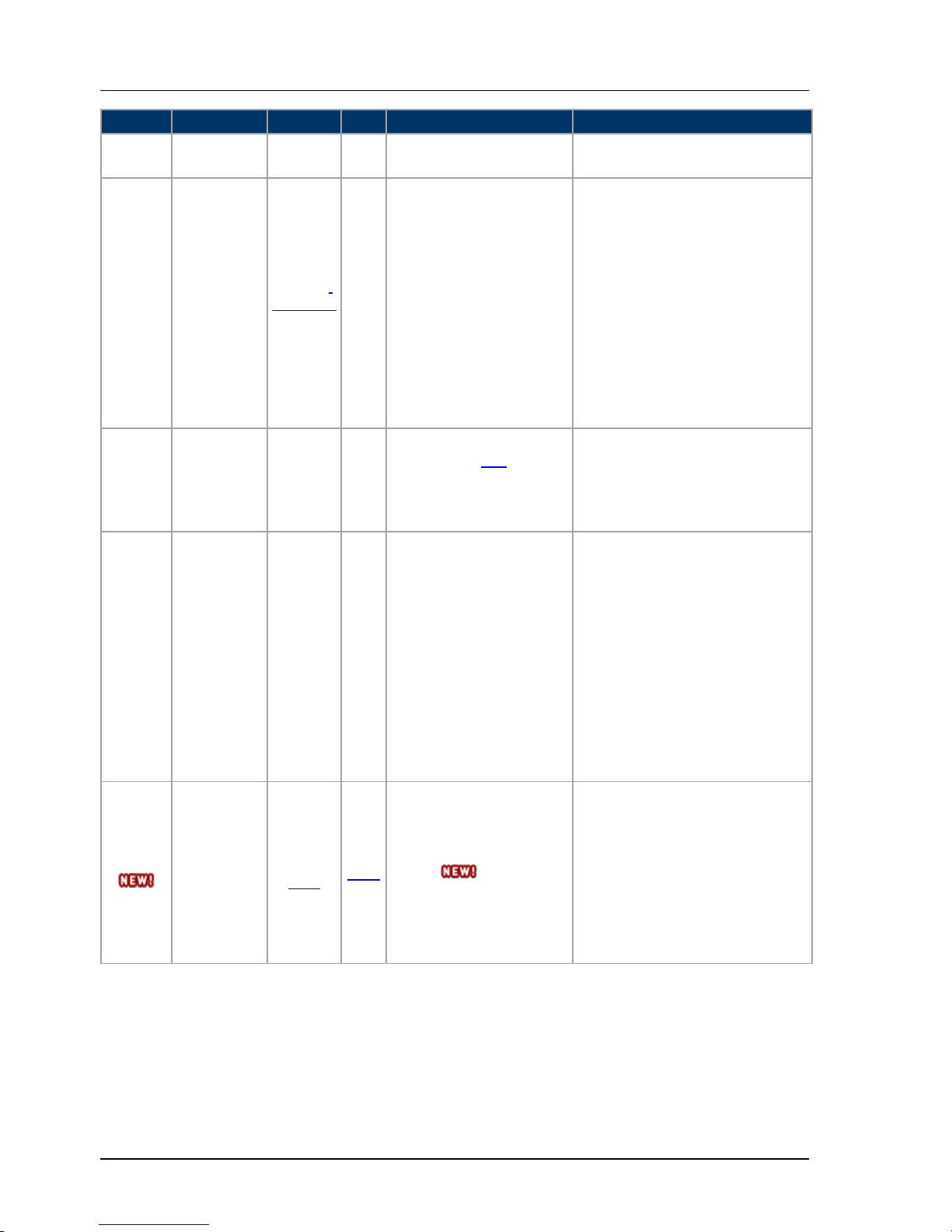
1.3 Camera Supporting Matrix
Note: Different versions or branches may have different feature support. If you are unsure, please
contact us to clarify the actual support of specific camera features.
Vendor
Connectivity
Video
Audio
Supported Features
Supported Model
AXIS HTTP
H.264,
M-JPEG,
RTSP
RTSP
• Video
parameters
setup
• Motion
event/setup
• Pan-Tilt-Zoom
with 8
directions and
free mode.
• Preset
set/recall.
• Focus control.
• Digital
input/output.
• Audio
out
(two-way).
M1011, M1011-W, M1031-W, M1054,
M1103, M1104, M1113, M1114, 1311,
P1343, P1344, P1346, P1347, P1343-E,
P1344-E, P1346-E, P1347-E, Q1755,
Q1755-E, 211W, 221, M3011, M3014,
M3113-R, M3114-R, M3203, M3204,
M3203-V, M3204-V, P3343, P3344,
P3346, P3343-V, P3344-V, P3346-V,
P3343-VE, P3344-VE, P3346-
VE, P3301,
P3304, P3301-V, P3304-V, 209FD,
216FD, 216FD-V, 216MFD, 216MFD-V,
212PTZ, 212PTZ-V, 214PTZ, 215PTZ,
215PTZ-E, P5512, P5522, P5512-E,
P5522-E, Indoor, P5532, P5534,
P5532-E, P5534-E, Q6034, Q6032-E,
Q6034-E, Q1910, Q1921, Q1910-E,
Q1921-E, 233D, Q6034, Q6032-E,
Q6034-E, 241S, 243SA, 247S, Q7401,
M7001, M7001, 240Q, 241Q, 241QA,
243Q Blade, Q7406 Blade, Q7404,
291 1U, Q7900
Arecont
Vision
AV2000
2.5.37
M-JPEG,
H.264
---
• Video
parameters
setup
AV10005, AV2805, AV1305, AV1355,
AV1300, AV1310, AV2105, AV2155,
AV2100, AV2110, AV3105, AV3155,
AV3100, AV3110, AV5105, AV5155,
AV5100, AV5110, AV3130, AV3135,
AV8185DN, AV8365DN, AV8185,
AV8180, AV8365, AV8360, AV1315,
AV2815, AV1325, AV2825,
StarDot HTTP
M-JPEG,
H.264,
RTSP
---
• Video
parameters
setup
• Motion
event/setup
• Auto
discovery.
• Digital
input/output
ExpressXL, NetCamXL,
NetCamSC, NetCamSCD
Page 16
Chapter 1. Introduction
16
Vendor
Connectivity
Video
Audio
Supported Features
Supported Model
IQinVision
HTTP M-JPEG ---
•
Motion event.
IQ755, IQ753
VIVOTEK VNDP-
080610
MPEG-4,
VV_H263,
M-JPEG
AAC,
AMR
• Motion
event/setup.
• Pan-Tilt-Zoom
with 4 directions.
IP8362, IP8162P, IP8162, IP8151P,
IP8151, IP7361, IP7142, IP8332,
IP8330, IP7330, IP8161, IP7161,
IP7160, IP7154, IP7153, IP7130,
IP8132, IP7134, IP7133, PZ71x2,
PZ71x1, PZ7152, PZ7151, PZ7132,
PZ7131, PT7137, PT7135, SD73x3,
SD7151, SD81x1, FD8361, FD8361L,
FD7141, FD8161, FD7132,
FD7131, MD7560, MD7530,
FD8134V, FD8133V, FD8134,
FD813
3, IP8352, FE8171V, SD8362E,
SD83x3E, SD83x2E, SD83x1E,
FD8362E, FD8362, FD8162,
SONY HTTP
MPEG-4,
M-JPEG,
H.264
G.711
G.726
• Motion event/
setup.[*1]
• Pan-Tilt-Zoom
with 8 directions.
SNC-RZ50N, SNC-RZ30, SNC-P5,
SNC-RX550, SNC-P1
ACTi SDK-10000 MPEG-4 PCM
• Video parameters
setup
• Motion
event/setup.
• Pan-Tilt-Zoom
with 8 directions.
• Preset set/recall.
• Digital
input/output.
ACM-5001, ACM-5601, ACM-5611,
KCM-5111, KCM-5211, KCM-5311,
TCM-5311, TCM-5601, TCM-5611,
ACM-1231, ACM-1431, TCM-1231,
TCM-1511, ACM-4001, ACM-4201,
TCM-4201, ACM-3001, ACM-3011,
ACM-3401, ACM-3411, ACM-3511,
ACM-3601, ACM-3701, ACM-7411,
KCM-7111, KCM-7211, TCM-3401,
TCM-3411, TCM-3511, TCM-7411,
TCM-7811, ACM-8511, CAM-6610,
CAM-6630, ACD-2000Q, ACD-2100,
ACD-2200, ACD-2300, ACD-2400,
TCD-2100, TCD-2500,
Brickcom
HTTP
H.264,
RTSP
RTSP
• Video parameters
setup
• Dual (multiple)
streaming.
• Audio out
(two-way).
• Digital
input/output
CB-102A Series, CB-101A Series,
FB-300A Series, FB-130N Series,
FB-130A Series, FB-100A Series,
FD-130A Series, FD-100A Series,
MD-100A Series, OSD-040 36x
Series, PZ-040 12x Series, VD-130A
Series, VD-100A Series
Page 17

Chapter 1. Introduction
17
Vendor
Connectivity
Video
Audio
Supported Features
Supported Model
Panasonic
HTTP
H.264,
RTSP
RTSP
• Video parameters
setup
• Pan-Tilt with 4
directions and
click-move-to.
• Preset set/recall.
• Focus control.
• Dual (multiple)
streaming.
BL-C2xx: BL-C230A/C210A
BL
-C1xx: BL-C121A/C101A,
C160A/C140A,C131A/C111A
BB
-HCM7xx: BB-
HCM701A/HCM705A,
HCM735A/HCM715A
BB
-HCM5xx: BB-
HCM547A/HCM527A/
HCM581A/HCM580A/H
CM531A/HC
M511A/HCM515A
PIXORD
HTTP
H.264,
RTSP
RTSP
•
Video parameters
setup
• Digital
input/output.
PD636, PD634, PB630(W), PD637,
P600, P606(W), PD614, P
-415M,
P
-416(W), P-413, P-400(W), P-426,
P
-412, P-405(W),PL621, P-423, P-
428,
P
-465, P463A, P463H, P600E, D634E,
P
-400 PoE, P-426 PoE, P-413 PoE,
PL621E, P
-423 PoE, PV6901, P-1401
(W,PoE), P-4000
Truen HTTP
H.264,
RTSP
RTSP
•
Video parameters
setup
• Digital
input/output.
• Motion event and
setup.
• Dual (multiple)
streaming
TCAM-330, TCAM-330W,
TCAM
-570-X10S, TCAM-570-X18H,
TCAM
-7300, TCAM-6300,
TCAM
-540-X10S, TCAM-530,
TCAM
-540-X18H, TCAM-531,
TCAM
-531BIR, TCAM-551,
TCAM
-551IR, TCAM-351, TCAM-
351IR, TCAM
-370-X10, TCAM-370-
X26/36,
TCAM
-370-X27/X33/X37, TCS-2000,
TCS-400, TCS-300, TCS-200
JVC
(V.Networks)
HTTP M-JPEG ---
•
Pan-Tilt-Zoom
with 8 directions
and click-move-to.
• Preset set/recall.
C30U, C625U, C655U,
VN
-V685U, VN-686U, VN-686BU
LILIN HTTP
H.264,
M-
JPEG,
RTSP
RTSP
• Pan-Tilt-Zoom
with 8 directions.
• Preset set/recall.
IPD552EX, IPR454, IPR458, IPS203,
IPS212, IPS303, IPS312, IPS125,
IPS130, IPS135, IPS025, IPS030,
IPS035, IPG012ES, IPD112ESX,
IPR312SX, IPR614ES, IPR618ES,
IPR414ESX, IPR418ESX, IPR712S,
VS012, BTE02S,
Page 18

Chapter 1. Introduction
18
Vendor
Connectivity
Video
Audio
Supported Features
Supported Model
ASONI HTTP
H.264,
M-
JPEG,
RTSP
RTSP
• Video
parameters
setup
• Motion event
and setup
• Digital
input/output.
• Pan-Tilt with
4 directions.
• Preset
set/recall.
• Focus control.
CAM613M, CAM616M(PoE),
CAM619M(PoE), CAM619MIR(PoE),
CAM620A(PoE), CAM620B(PoE),
CAM624M(PoE), CAM62
7(PoE),
CAM636M(PoE), CAM628M(PoE),
CAM629(PoE), CAM614(W,PoE),
CAM638(W), CAM639(W),
CAM634M(W), CAM615(PoE),
CAM646MIR(PoE), CAM635(PoE),
CAM640, CAM641, CAM630,
CAM630A(PoE), CAM630B(PoE),
CAM633, CAM633A(PoE),
CAM633B(PoE), CAM647,
CAM647A(PoE), C
AM647B(PoE),
CAM416(PoE), CAM419(PoE),
CAM419IR(PoE), CAM422M(PoE),
CAM428M
-PoE, CAM436(PoE),
CAM439(W), CAM441, CAM415(PoE),
CAM424(PoE), CAM425(PoE),
CAM426(PoE), CAM427(PoE),
CAM428(PoE), CAM450,
CAM413(PoE,W), CAM417(PoE),
CAM418(PoE), CAM435(PoE),
C
AM437(PoE), CAM438(W),
CAM415(PoE), CAM419(PoE),
CAM419IR(PoE), CAM435(PoE),
CAM436(PoE), CAM437(PoE),
CAM420A(PoE), CAM420B(PoE),
CAM450, CAM451, CAM451A(PoE),
CAM451B(PoE), SVR640, SVR611,
SVR610, SVR410, SVR440, SVR411,
ZAVIO HTTP
RTSP,
MPEG-4,
M-JPEG
RTSP,
G.711
• Video
parameters
setup
• Pan-Tilt-Zoom
(8 directions)
• Preset
set/recall.
• Focus control.
• Digital
input/output.
F210A, F312A, F3100, F3105, F3101,
F3106, F7110, F7115, B5110, F531E,
F731E, D5110, D5111, D7110, M511E,
M511W, P5110, P5115, V111T
Page 19
Chapter 1. Introduction
19
Vendor
Connectivity
Video
Audio
Supported Features
Supported Model
CTC-U HTTP
H.264,
RTSP
RTSP
• Pan-Tilt zoom (8
directions)
• Preset set/recall.
• Focus control.
• Digital
input/output.
DVS-8501E, DVS-8501E-H, DVS8504E
-FD, DVS-8504E-H, DVS-8301,
IPCAM
-8318P, IPCAM-8318F, IPCAM-
8309D,
IPCAM
-8309FW, IPCAM-8309F,
EtroVision
EtroSDK 1.31
MPEG-
4, H.264
---
• Video parameters
setup
• Pan-Tilt-Zoom
with 4 directions
• Preset set/recall
• Focus control
EV6150 Series, EV6150A Series,
EV6151A, EV6153A, EV6156A,
EV6551A Seri
es, EV6551A-DI,
EV6552A, EV6552R, EV8150A,
EV8180F, EV8180U, EV8780U,
EV8580U Series, EV8580F, EV8180A,
EV8580A Series, EV8780A, EV8781A,
EV8781D, EV8781F, EV8781U Series,
EV6353A Series, EV6355A Series,
EV6356A Series, EV6750, EV6250A
Series, EV3150A, EV3151, EV3151A,
BOSCH
VideoJet
HTTP
M-JPEG ---
• Pan-Tilt with 8
directions
VideoJet-10
RTSP Supporting Information
Supported Video Codecs MPEG-4, M-JPEG, H.264
Supported Audio Codecs G.711, AAC, AMR, G.726, MPEG audio
Supported Transport Modes UDP, TCP, HTTP
Remarks
• VV_H263: A variation of proprietary H263 developed apparently by VIVOTEKV_H263">.
• [*1] Not all models are supported. Known supported models are RZ50, RX550
AVI-Export Supporting Information
Supported Video Codecs MPEG-4, M-JPEG, H.264
Supported Audio Codecs G.711, PCM
Page 20
Chapter 1. Introduction
20
1.4 Getting Started with CTC Union NVR
Installation and Initialization
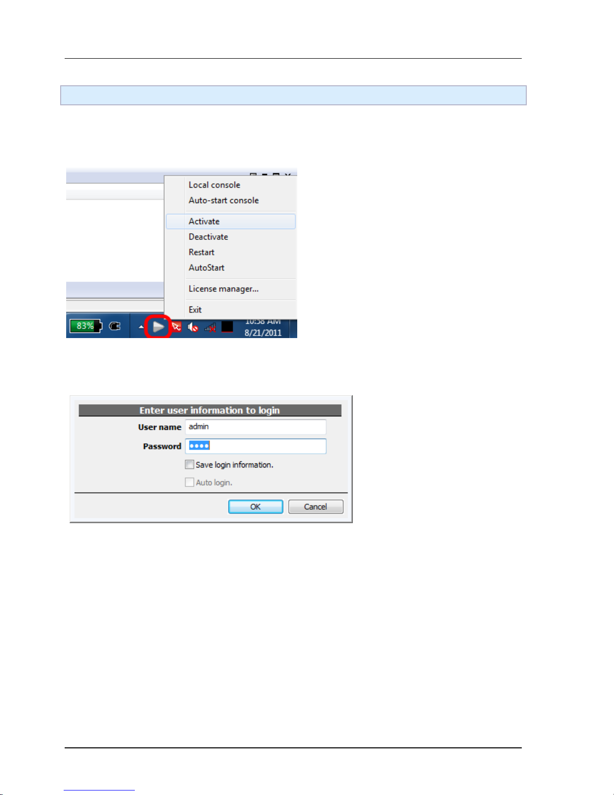
The installer will install a Windows service. You can manage it with our organizer, a triangle in Windows
task-bar. When the triangle is green, you are good to go.
Invoke the console to interact with the server. Default account/password is admin/1234.
Page 21
Chapter 1. Introduction
21
Minimum Configuration
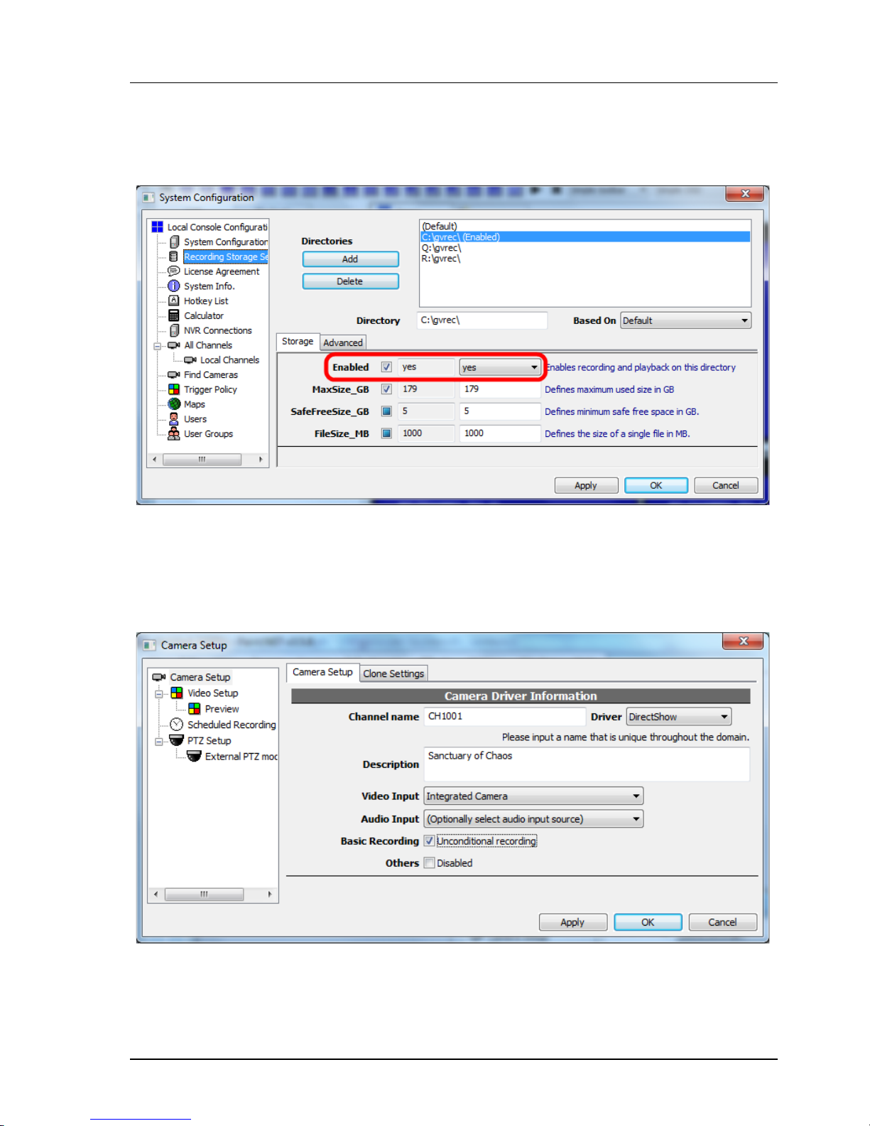
The first thing you need to do is configuring storage. All available drives are listed automatically. Just
enable the drive you want to use to store recorded data. You may want to change "MaxSize_GB" if the
drive is not dedicated to recording. Everything else should be left untouched.
The second to do is adding a camera. Channel name is an unique identification associated with recorded
data and events. It can't change in the future so name it carefully. Put additional information in description
instead. Select driver DirectShow for webcam. Check "unconditional recording" for 24x7 recording.
Okay. Now the setup is done and the server is recording. The server is running as long as the PC is on, even
before any user logged in Windows.
Page 22
Chapter 1. Introduction
22
Things You May Want To Know
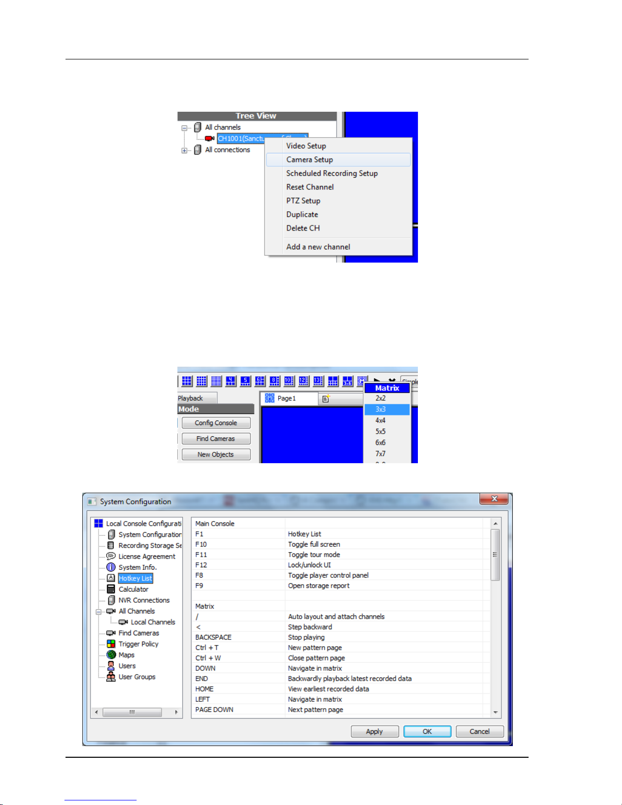
Configure camera, and many things as well, with right click menu.
Cameras, maps, and some objects can be dragged. Experiment with various operations with mouse drag &
drop
Use matrix mode for better performance. Decoding massive channels with massive resolution consumes
hell lot of computing power. Use simplified player (no OSD, no aspect control, no zoom, no playback, no
audio) for better performance.
List all hot-keys.
Page 23
Chapter 1. Introduction
23
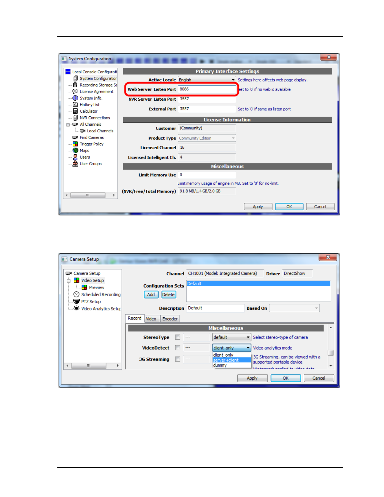
Configure for IE access.
Enable intelligent video analytic on server in camera configuration. You don't want to do this if the server is
not dedicated to surveillance. To analyze video, the engine must decode it first so it consumes fair amount
of computing power.
Page 24
Chapter 1. Introduction
24
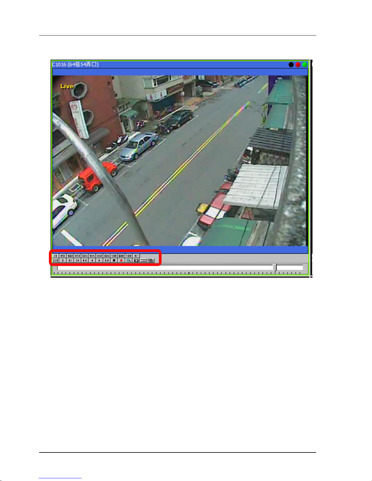
Some of the indicators in player is clickable
Page 25

Chapter 2. NVR System Installation
25
Chapter 2.
NVR System Installation
2.1 Introduction
The NVR software is typically deployed from a CDROM. This is how the software is distributed as a package.
It is also possible that the installation program might have been downloaded from CTC Union's website, in
which case the setup software is packaged in a ZIP file.
The following procedure will assume that we are installed the CDROM distribution.
2.2 NVR System Requirements
Recommended System Requirement
Operating System Microsoft Windows XP/Windows 7/Server 2008
CPU Multi-core CPU
System Memory 2G (or more)
Graphics Nvidia or ATi Hi-performance graphics card
Video RAM
128MB (or more)
Required Space At least 40MB for installation
Others Requires DirectX 9
2.3 Software install
2.3.1 Server V.S Client
There are two software packages for NVR, one server, and one client. The server software provides the
main recording functions. It captures the video streams from the network cameras, provides live view and
records to local storage.
Client PCs view video from the server. A PC may simply use Internet Explorer web browser to view video, or
if using the client software, may local record streams from the server. The client software cannot record
the streams from the network cameras. That function is reserved for the server.
Page 26
Chapter 2. NVR System Installation
26
2.3.2 Exploring the CD contents
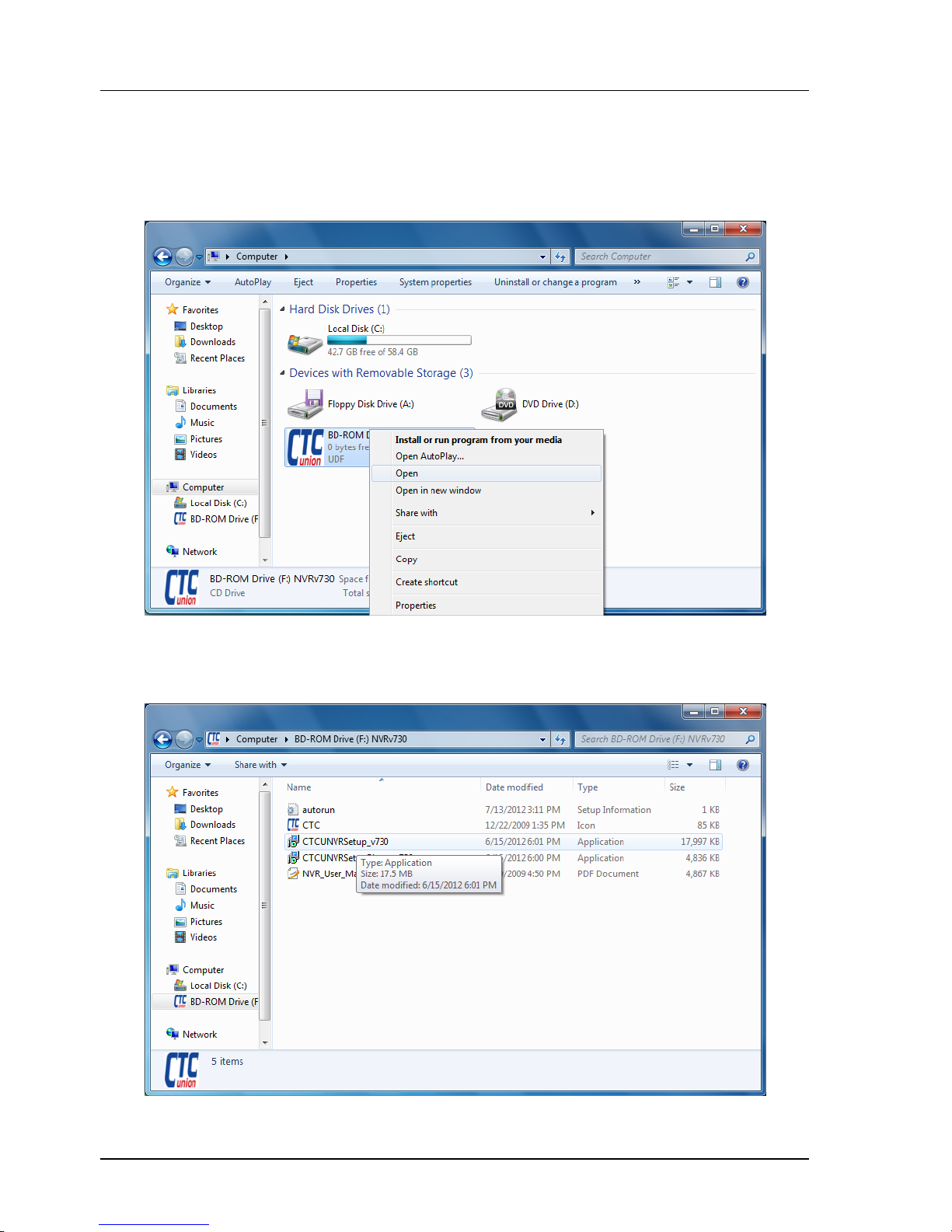
Place the installation CD into the PC's CD/DVD drive. If the installation does not auto-run, click the
Window's 'Start' button and select 'Computer'. Locate the drive containing the installation media, click with
the 'Right' mouse button and from the pull-down window select 'Open'.
Below the contents of the CD are shown. There are two setup files, one for installing the NVR server, the
other for installing only the NVR client software. The user manual is also included on the CD and is in PDF
format. The PDF can be opened using Acrobat Reader, Foxit Reader, or any other free PDF reader software.
Page 27
Chapter 2. NVR System Installation
27
2.3.3 Installing the Software
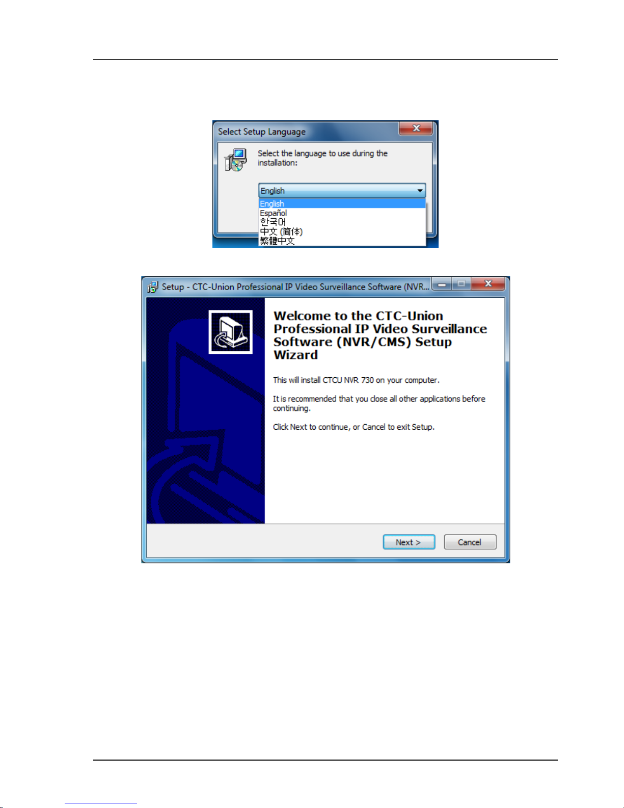
Locate the file called 'CTCU NVR Setup vXXX' and double-click it to start the NVR installation.
Select the language to use during installation.
Click 'Next' from the 'Welcome' screen to continue the setup or 'Cancel' to exit setup.
Page 28
Chapter 2. NVR System Installation
28
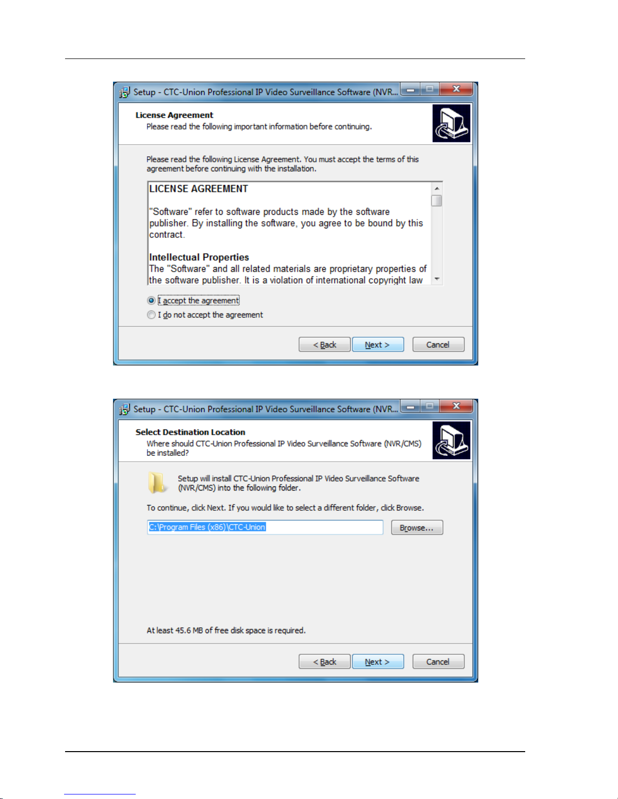
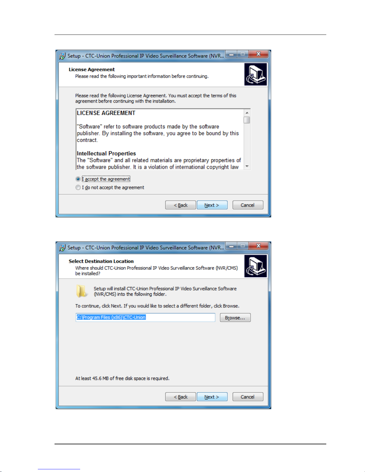
You must click the radio button "I accept the agreement" to the EULA (End User License Agreement) before
you can install the software. After accepting the agreement, click 'Next' to continue.
The default installation directory can be changed through this "Select Destination Location" screen. We
recommend leaving the system default location which would be "C:\Program Files" for 32 bit OS or
"C:\Program Files (x86) for the 32 bit folder on 64 bit OS. Click 'Next' to continue.
Page 29
Chapter 2. NVR System Installation
29
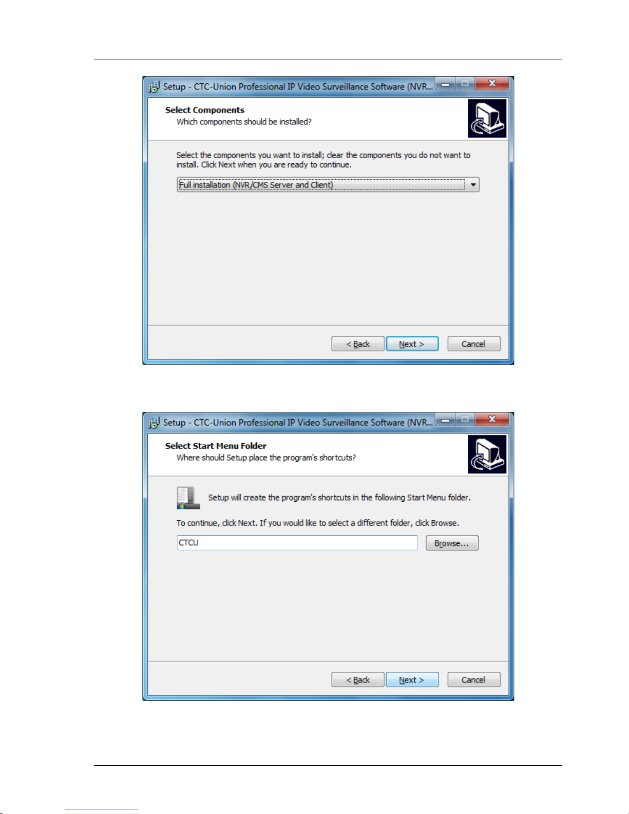
It is possible to only install the client portion of the software from the main server installation program. But
in our case we will be sure to choose "Full installation (NVR/CMS Server and Client). Click 'Next'.
From the "Select Start Menu Folder" window the default program shortcut name can be changed. Click
'Next' to continue.
Page 30
Chapter 2. NVR System Installation
30
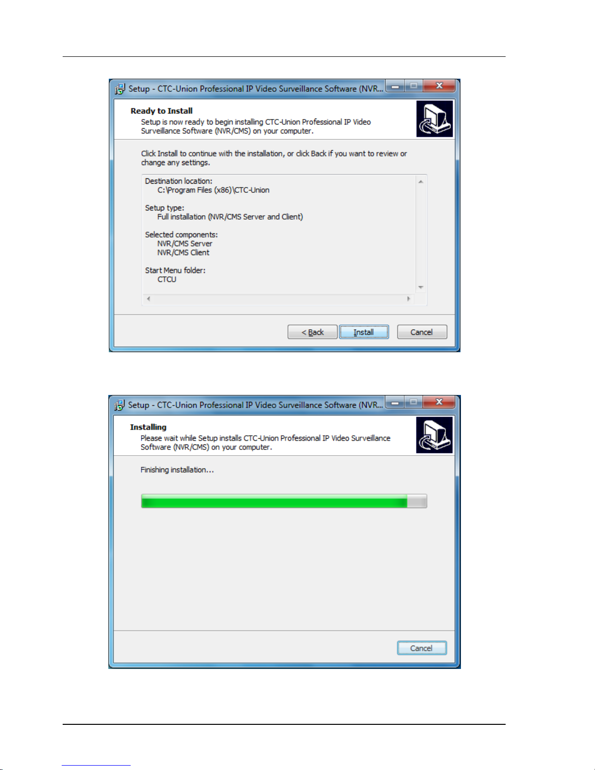
Now that all information has been gathered, the program is ready to be installed. If you 'Cancel' at this
point, you must start installation all over again. Click 'Install' now to install the NVR server program.
The "Progress Bar" will indicate the progress of the NVR installation.
Page 31
Chapter 2. NVR System Installation
31
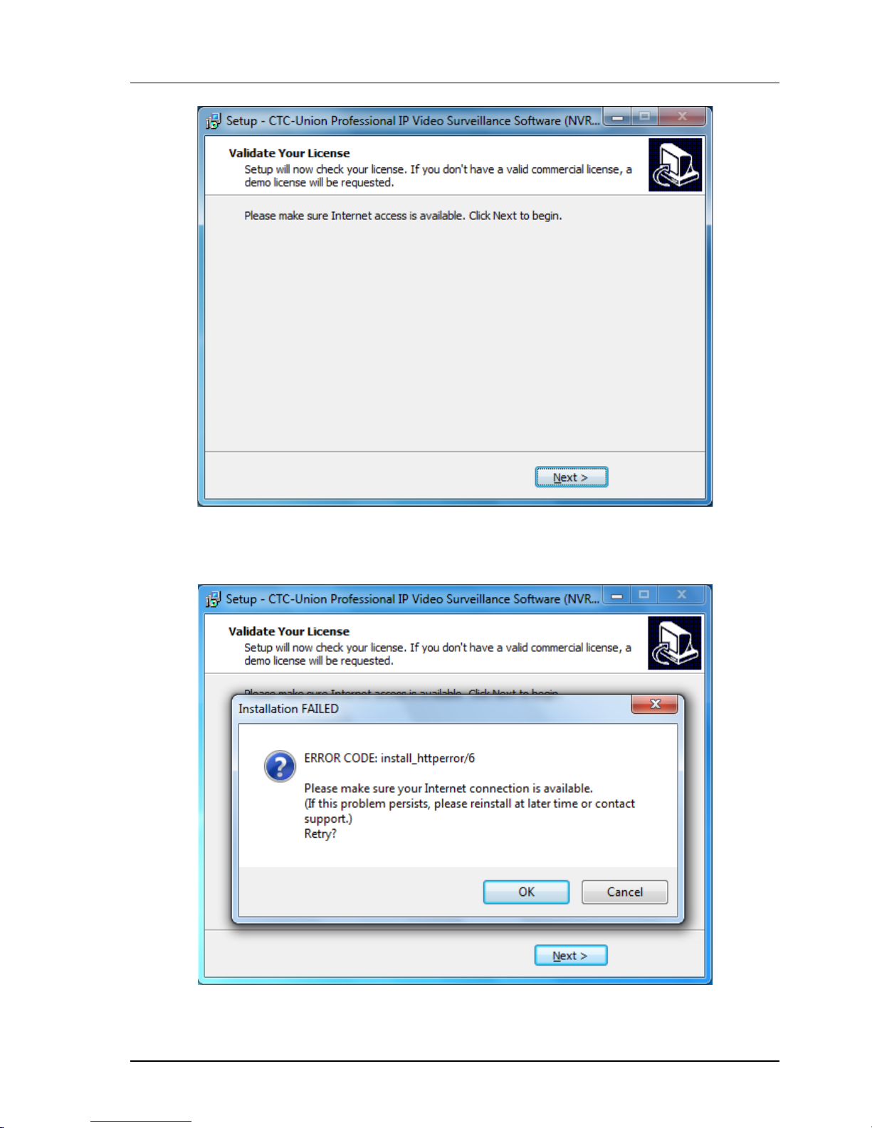
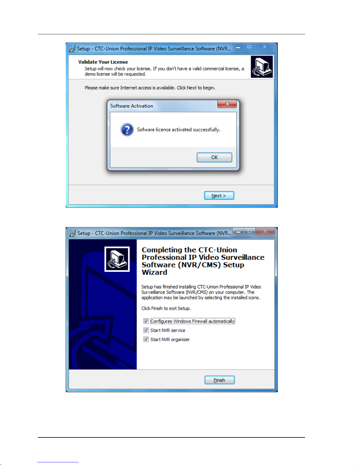
The next step of the installation will validate your NVR license. You must be connected to the Internet in
order for License Verification to succeed. If you do not yet have a license, you still must be connected to the
Internet. The NVR will run in 'Demo License' mode, supporting a maximum of only 4 cameras.
If there is a problem with Internet connection, the above error code will be displayed. The NVR installer
must be able to contact the License Server.
Page 32
Chapter 2. NVR System Installation
32
The software has been installed and is running in Demo mode.
The final step of the setup is the configure which windows "services" will be launched. Select all three items
and then click 'Finish'.
Page 33
Chapter 2. NVR System Installation
33
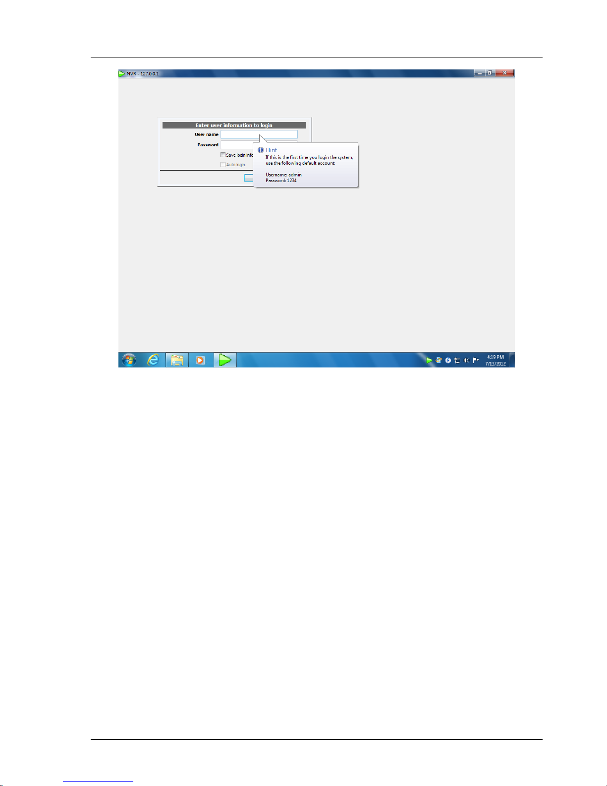
The NVR is now installed and running. The default username and password are "admin/1234".
Page 34
Chapter 2. NVR System Installation
34
2.3.4 NVR Client installation
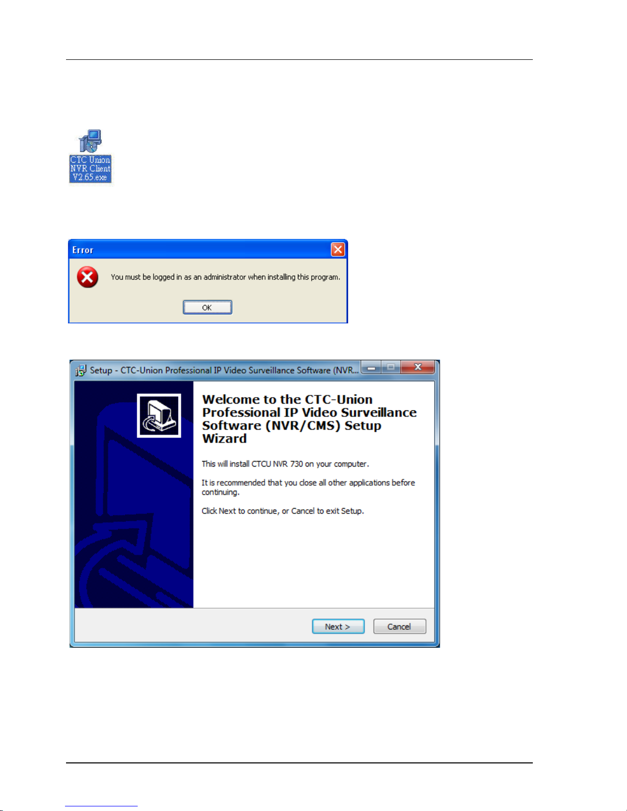
Locate the installation files. You may have these files on CDROM or they may have been downloaded from
CTC Union's website. In either case, double-click the client install file.
Administrative privileges are required in order to install this software. If you see the following message,
either logout and log back in as 'administrator', log in with another account that has administrative
privileges or add administrative privileges to your user account.
Start to setup wizard
Page 35
Chapter 2. NVR System Installation
35
Continue with setup by clicking the 'Next >' button.
You must accept the License Agreement by selecting the radio button, then click 'Next >'.
Use the 'Browse…' button to select a different location to install the program, or press 'Next >' to continue.
Page 36
Chapter 2. NVR System Installation
36
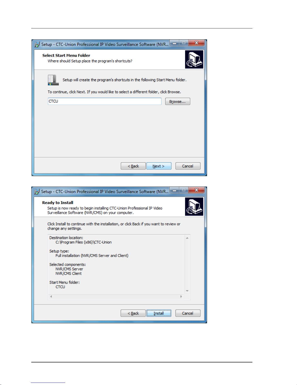
Click 'Next >' to continue with the assigned program start folder.
Review the settings and then click 'Install'.
Page 37
Chapter 2. NVR System Installation
37
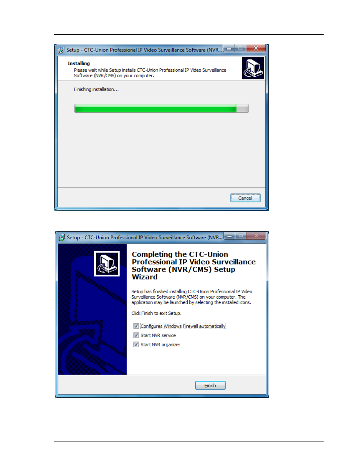
The setup now proceeds to install the program.
By default, just leave one check boxes checked and then click 'Finish'.
Page 38
Chapter 2. NVR System Installation
38
2.4 Start NVR Service
At installation complete screen, you can choose "Start NVR service" to start the NVR service. You can also
invoke this by using "Start Menu"=>"Programs'=>" NVR organizer"=>"Start NVR service
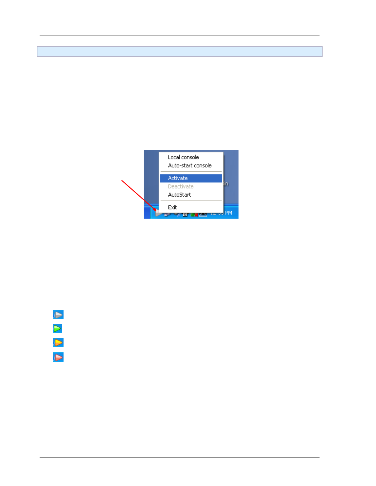
If the installation is properly done and service is started, you will see a gray triangle-shaped icon in the trayicon area (usually at the right-bottom side of the screen)
Use the Tray Icon
The NVR has an icon that will reside in the toolbar. The icon is 'green' in color when the NVR is activated.
To activate the NVR, right-click the toolbar icon and select 'Activate' from the pop-up window. If you
select 'Auto-Start' the NVR will automatically activate on Windows startup or login.
The color of the tray icon indicates the system status:
The NVR is offline.
The NVR is online.
The NVR will be auto-started very soon
The NVR is busy starting up or shutting down.
Page 39
Chapter 2. NVR System Installation
39
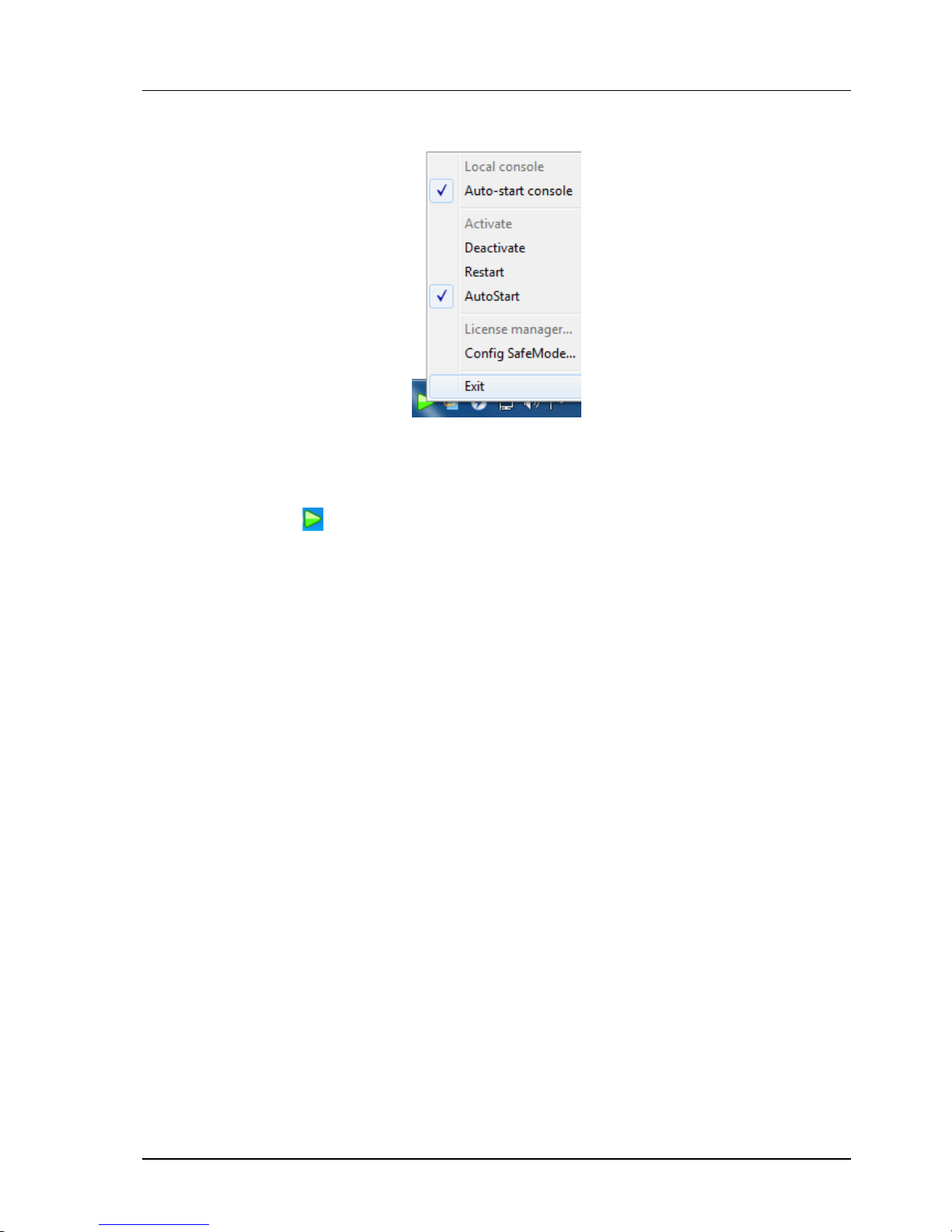
You can right-click on the tray-icon to change the system state:
In production environment, you should configure your NVR as "Auto-start", so it will
automatically start on system start-up, and it will also automatically restart after abnormal
shutdown.
Right click the icon ,and click “Local Console” to login.
If there are no accounts existing in the system, an administrator account is automatically
created:
Default accounts
Account:admin
Password:1234
It is essential to change the password right after first login to ensure the security of the
system. Please refer to related pages in this section about how to perform password change
to a specific account.
Page 40

Chapter 2. NVR System Installation
40
This page left blank intentionally.
Page 41

Chapter 3. VIDEO STREAMING AND CHANNEL SETTING
41
Chapter 3.
VIDEO STREAMING AND CHANNEL SETTING
3.1 System Requirements
Minimum System Requirement
Operating System Microsoft Windows XP / Windows 7 / Server 2008
System Memory 1G
Video RAM 64MB
Others Requires DirectX 9 preinstalled
Recommended System Requirement
Operating System Microsoft Windows XP
CPU Multi-core CPU
System Memory 2G
Video RAM 128MB
Others Requires DirectX 9 preinstalled
3.2 Download Setup
Downloading
Log in to the partner web and selects the "Licensed Install". Select proper component to install.
Download the setup package into local folder and execute it.
Activating License
There are two ways to properly activate your license. One is to use our USB-dongle-key. The other is use
Online License Authorization.
If the product is not properly licensed, it won't work correctly.
Starting NVR ServiceAt installation complete screen, you can choose "Start NVR service" to start the NVR
service. You can also invoke this by using "Start Menu"=>"Programs'=>"NVR organizer"=>"Start NVR
service"
If the installation is properly done and service is started, you will see a gray triangle-shaped icon
in the tray-icon area (usually at the right-bottom side of the screen), like the following picture.
Page 42

Chapter 3. VIDEO STREAMING AND CHANNEL SETTING
42
3.3 Using Online License Authorization
Concepts
Online license authorization offers software publisher a more flexible way to sell license and to eliminate
additional logistic cost. In NVR system, it even gives the flexibility to license software in per-single-channel
basis. Therefore it's more cost-effective to the customers.
In our system, there are two types of license:
Online license: This type of license requires periodic Internet check of license validity. It allows users to
transfer license from one computer to another, as long as the maximum concurrent license does not
exceed the purchased ones. In most scenario, this offers greatest flexibility, highest cost efficiency, and
minimum risk.
Offline license: This type of license does not require Internet when normal operation. However it needs to
be "bound" to a specific computer. The operation to bind a license to a computer is called "commit
". If you
committed a license to a computer, it became fused to that specific computer state (including its system
and the underlying hardware). If you change the underlying system or hardware, you risk losing the license.
It is generally recommended unless situation is required, one should avoid using offline license and choose
the online one. Even if offline scenario is required, one should start from using online license. After a
period of stable running, one can always convert online license directly to offline ones through the process
of committing
.
To generate effective license (called authorization code, or auth. code), one need two
elementsRequest code: This code contains information about target computer, number of channels and
type of product requested.
Purchase code: This is the code that you paid money for. (Giving away this code is same as giving
away your money. So you need to keep it in secret.)
In online environment, the request code is transparent (invisible) to users. You only need to input
purchase code in the GUI to get authorized. However, in some special environment, where Internet access
is not possible, we also offer an offline way to activate license. In this scenario, you must generate a
request file (which contains encrypted request code), copy it to a portable storage device, and bring it to a
computer where Internet access is available.
Page 43

Chapter 3. VIDEO STREAMING AND CHANNEL SETTING
43
In addition to the types of license, there are some attributes associated with a specific license. Depending
on actual business terms, a license might have a number of following properties:
Forced online license: If a license has this attribute, it cannot be committed to computer. If you try
to do that, it will fail (Offline Install Forbidden). This is needed in some business terms to enforce
certain licensing policies.
Limited (Expire able) license: A license may subject to expire after certain date (either demo
license or not). This kind of license implies "forced online license".
Demo/Evaluation: If a license has this attribute, the program will display an evaluation notice
stating that "using the software in production environment of any kind is strictly prohibited". This
is needed for customers who want to try the software before paying. The function of the program
is, however, almost same as the formal one. Demo version implies "forced online license" and
"limited license" (the reverse is not true). A demo license can be transparently converted to
formal one by paying fees to clear the demo flag on the server. The user only needs to restart the
NVR engine to obtain formal license automatically.
Page 44
Chapter 3. VIDEO STREAMING AND CHANNEL SETTING
44
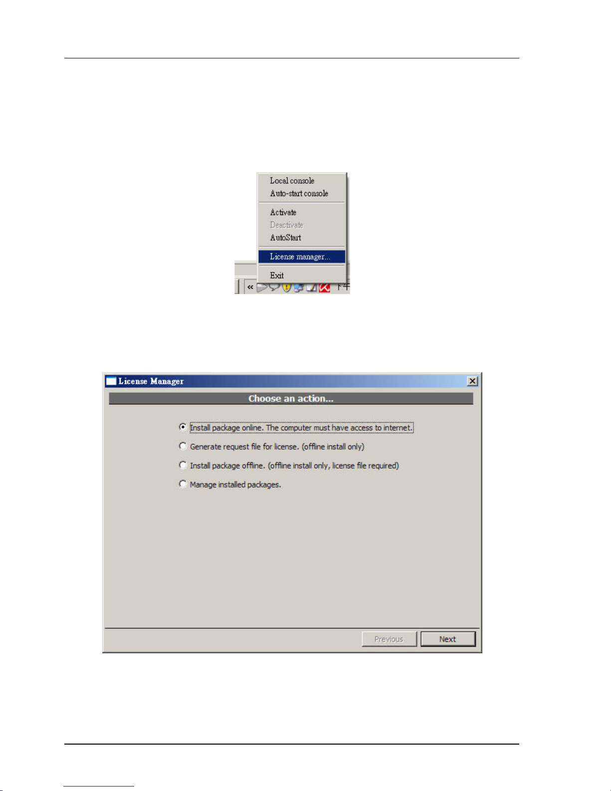
On systems like Windows Vista or Windows 7, where administrative privilege is often not given in default
scenario, you will need right-click NVR organizer and select "Run as administrator" to let the program gain
administrative access.
The NVR engine service must NOT be also running. That is: only one of NVR engine and License Manager
can be running at the same time. They are, sort of, exclusive to each other. If you try to start NVR engine
service while License Manager is running, it will cause the NVR service license check to fail.
License Manager - Install package online
The fastest and most convenient way to install package is through "Install package online" option. You will
need unrestricted access to the Internet to use this option. Please note however, using this option means
you will need Internet even in normal operation, as License Manager will check in the background
periodically for license validation. (see Concepts.)
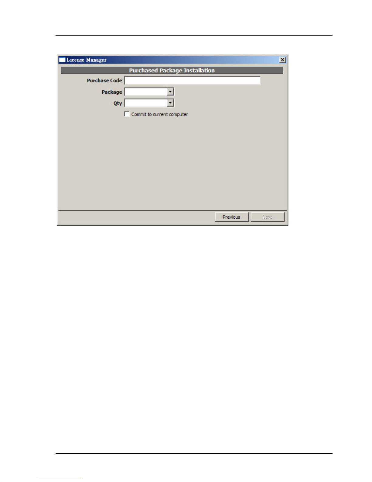
After clicking "Next", following screen will appear. You need to enter purchase code, package, and desired
quantity. Please note the desired quantity must not exceed the remaining purchased quantity. If you
check the "Commit to current computer" box, this will became an offline license (unless the licensing
terms doesn't allow that). You can always convert an online license to an offline one later.
Page 45
Chapter 3. VIDEO STREAMING AND CHANNEL SETTING
45
Package Types
There are 3 types of packages, when selecting license to install:
"std": This means the NVR Standard edition.
"pro": This means the NVR Professional edition.
"ipr": This means the NVR Intelligent edition.
The prices for different packages are different. Please note however, you cannot mix installing "std" and
"pro" packages on the same computer. If you do so, "std" packages will be hidden and disabled, becoming
useless. On the other hand, you can mix "pro" and "ipr" packages freely on the same computer.
Page 46
Chapter 3. VIDEO STREAMING AND CHANNEL SETTING
46
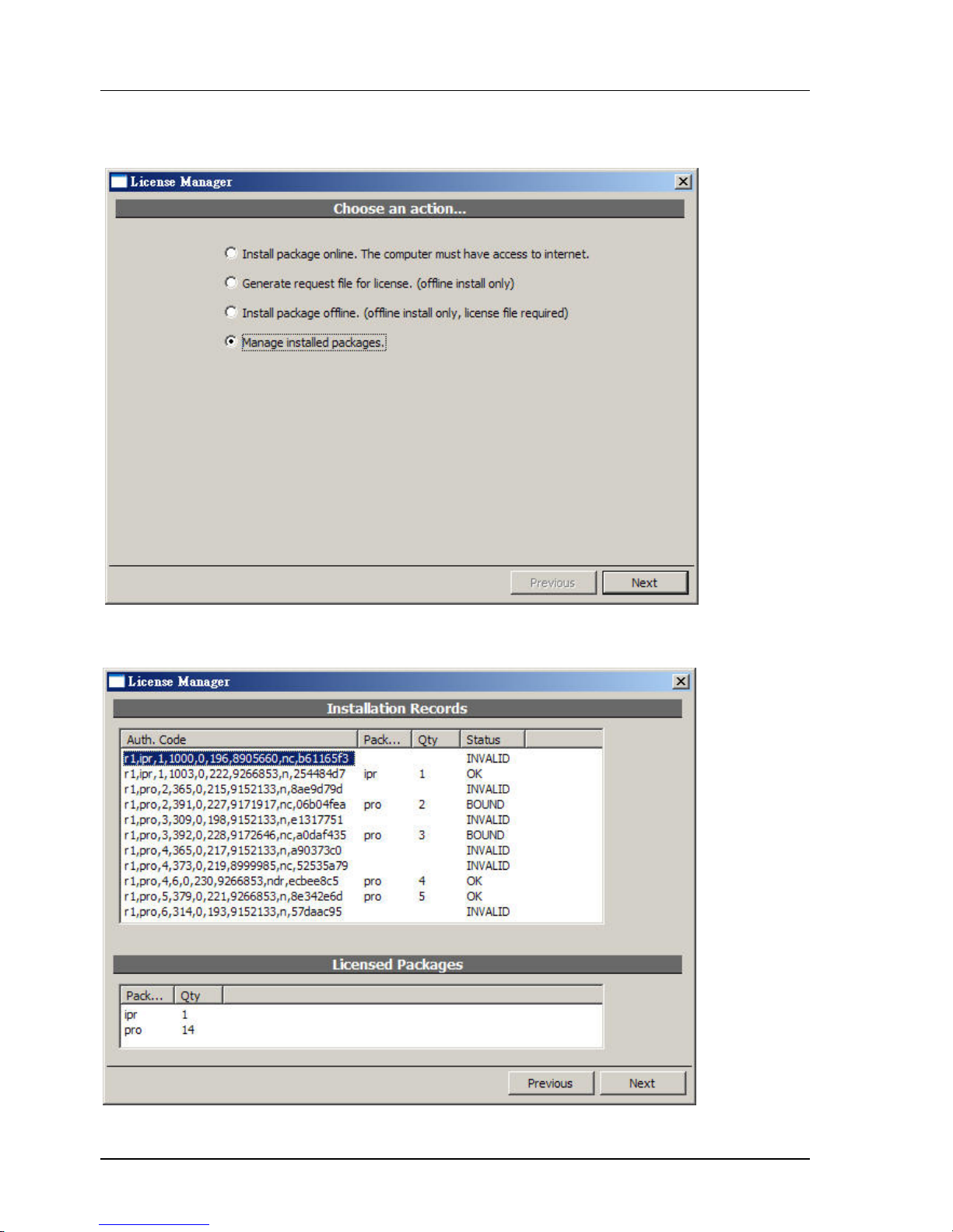
Managing Installed License
To manage installed license, select the indicated item:
Following screen will appear:
Authorized packages
Page 47

Chapter 3. VIDEO STREAMING AND CHANNEL SETTING
47
Below explains license status:
"OK": This online license works correctly.
"NEW": This is a newly installed license.
"BOUND": This is an offline (committed) license which works correctly.
"UNKNOWN": This license is currently working (and is previously known working). But due to some
factors (such as lacking Internet connection or exceeding maximum concurrent license), it might soon
be invalidated.
"FAIL": This license is invalidated, mostly likely due to license check failure, or license revoked at
server-side.
"INVALID": This license is invalidated, mostly likely due to computer system change.
If you want to commit a online license to current computer, right-click on that license and bring up a
context menu. Select "Commit..." to perform the commit operation. You'll need Internet connection to
perform this operation.
Page 48
Chapter 3. VIDEO STREAMING AND CHANNEL SETTING
48
3.4 Starting the Service
Use the Tray Icon
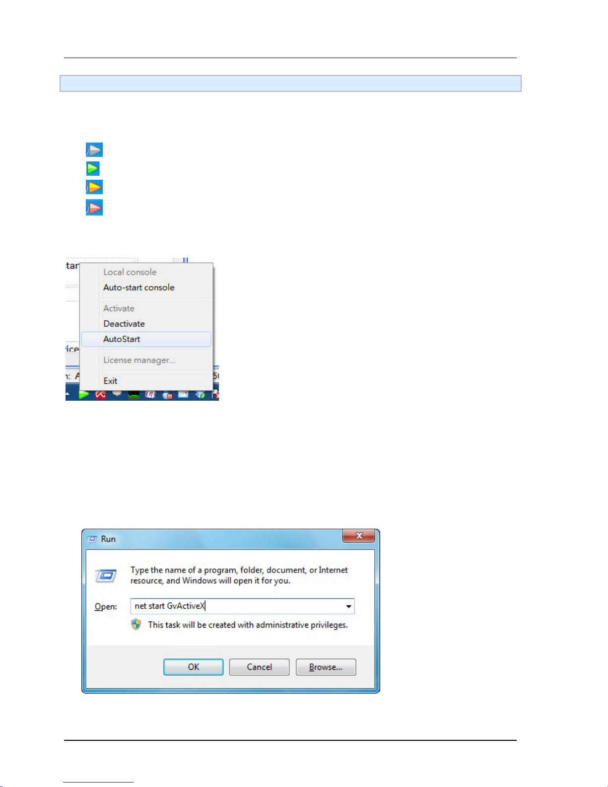
The color of the tray icon indicates the system status:
The NVR is offline.
The NVR is online.
The NVR will be auto-started very soon
The NVR is busy starting up or shutting down.
You can right-click on the tray-icon to change the system state:
In production environment, you should configure your NVR as "Auto-start", so it will automatically start
on system start-up, and it will also automatically restart on abnormal shutdown.
Alternative Way to Activate NVR
The tray icon manager of the CTC NVR should automatically appear . If it's not, you can activate the tray
icon by using Windows service manager to start service "ActiveX".
You can do so by either
(1) Start a service using "net" Command Use "Start Menu"=>"Run"
A dialog will appear. Now enter "net start ActiveX" and press ENTER.
Page 49
Chapter 3. VIDEO STREAMING AND CHANNEL SETTING
49
(2) Start a service using Windows service manager consol
Use "Start Menu"=>"Settings"=>"Control Panel"=>"Administrative Tools"=>"Services"
Locate "ActiveX"
Right-click and select "Start".
Note: Sometimes the GUI of the service manager is not updated so you will be unable to select the "Start"
from context menu. In this case, press F5 to refresh the GUI.
3.5 Setup for Multi-monitor
3.5.1 Consoles and Profiles
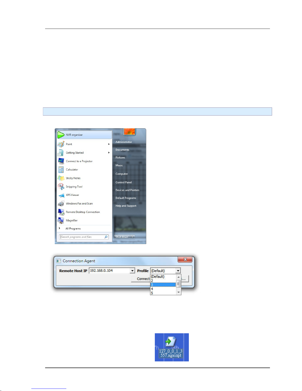
A profile stores states and settings associated with a
local console, including the window position, layout,
saved login information, IP address of server... etc. To
invoke a console with specific profile, click Connect to
remote NVR in CTC Union in Start Menu. Connection
Agent dialog will be opened.
To select a profile, use the Profile combo box.
IP address of the remote server must be specified before connecting. If the server and console is on the
same computer, enter 127.0.0.1 in IP address.
Click Make Shortcut... button and a shortcut will be created in windows desktop. Simply double click
on the shortcut and the console with this profile will be invoked. Rename the shortcut or it may be
overwritten next time a shortcut is created.
Page 50
Chapter 3. VIDEO STREAMING AND CHANNEL SETTING
50
3.5.2 Multi-monitor
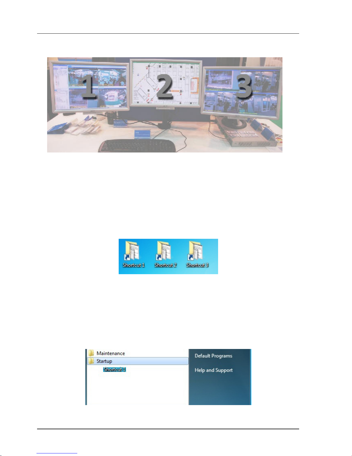
The following demonstrates how to setup CTC Union NVR for multi-monitor. The example uses 3
monitors but this can be applied to more or less monitors as well.
1. Set the multi-monitor to Extended mode in Windows. This is not a requirement but it's
recommended for easier setup and more intuitive operations. In extended mode, multimonitor act as a single desktop. Just navigate the mouse cursor in different monitors to
access them. For more information, refer to the manual provided by video card vendor.
2. Create 3 shortcuts with different profiles. They may connect to the same NVR server or
different ones. Or they may connect to local host using 127.0.0.1 as IP address.
3. Invoke the consoles using the shortcuts. There will be 3 windows. Move them to the
monitors you want to place in and change the layout. To move among different monitors,
simply move the mouse to the left/right edge of the monitor.
4. For best viewing experience, close menu of some consoles by pressing F10 on keyboard.
5. Next time the shortcuts are clicked, the consoles will be invoked as their last states and
layouts. The shortcuts can also be placed in the Startup of Windows Start Menu.
Page 51
Chapter 4. SYSTEM CONFIGURATION
51
Chapter 4.
SYSTEM CONFIGURATION
4.1 Log-in for first-time
Default accounts
If there are no accounts existing in the system, an administrator account is automatically created:
Account Name admin
Password 1234
It is essential to change the password right after first login to ensure the security of the system.
Please refer to related pages in this section about how to perform password change to a specific
account.
4.2 Change Active Locale
4.2.1 Concepts
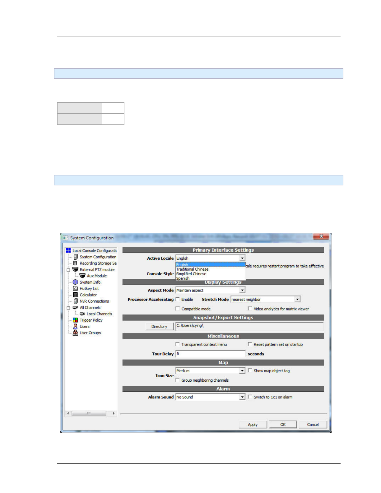
CTC Union NVR is designed as fully multilingual. Because of this, the factory default is set as English. You
can change this by selecting "Cfg. Console":
Following dialog will appear.
Select the first combo-box to change to your locale. After this, you need to restart the system to make the
setting change take effective.
Page 52
Chapter 4. SYSTEM CONFIGURATION
52
4.3 Configuration video storage
4.3.1 GUI Overview
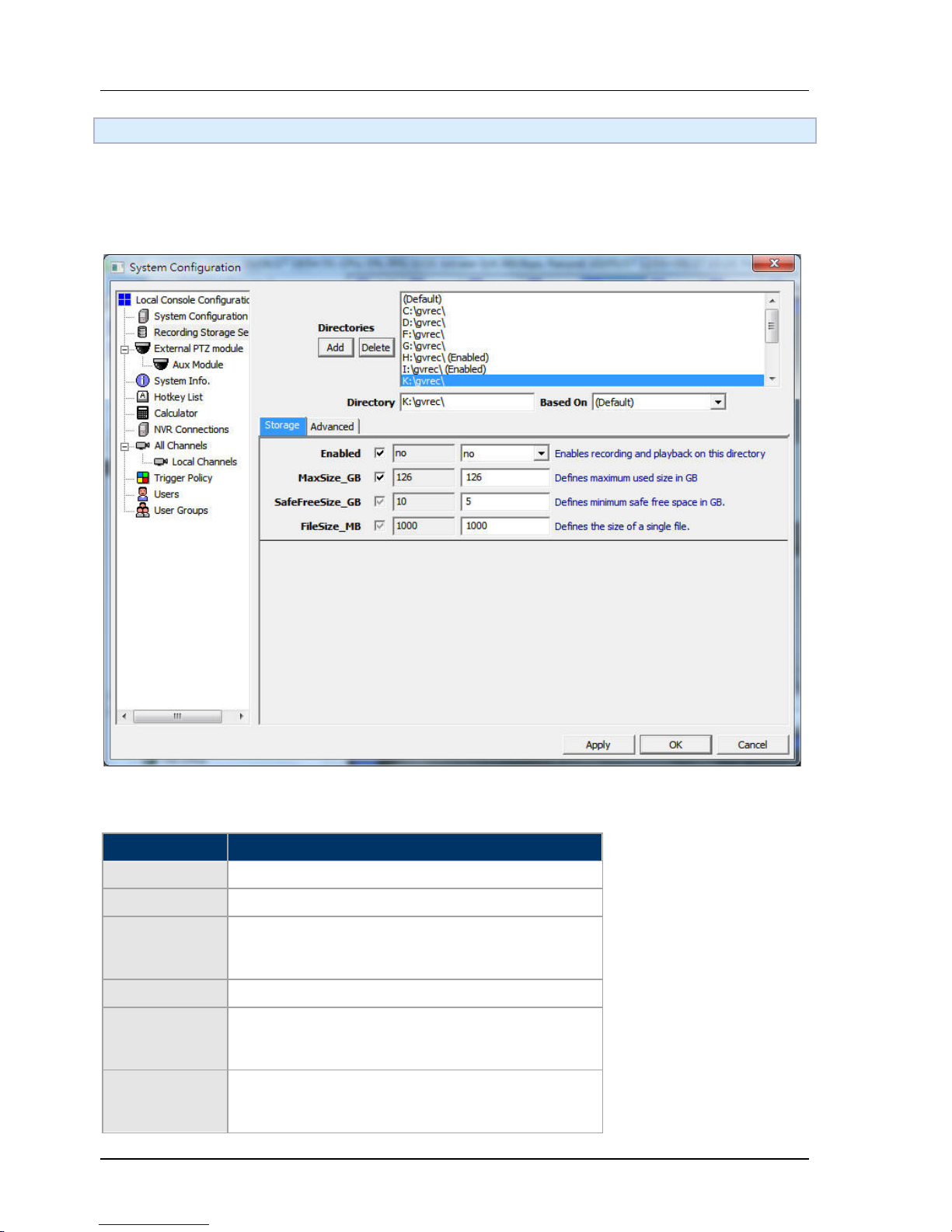
Click on the "Cfg. Storage". Following dialog box will appear. If no directories have been enabled, this dialog
will appear automatically after login.
4.3.2 Storage Space Parameters
Parameter Description
Enabled Is the directory enabled?
MaxSize_GB Maximum space the recording process will utilize.
SafeFreeSize_GB
Safe-guard of free space. If free space is lower than
this value the system will start to recollect space from
old video data.
FileSize_MB The size of a single file.
ReadCache_MB
This is the global setting of storage system read
(playback) cache. Adjust this value according to your
available memory and required performance.
WriteCache_MB
This is the global setting of storage system write
(record) cache. Adjust this value according to your
available memory and required performance.
Page 53
Chapter 4. SYSTEM CONFIGURATION
53
4.4 Adding a channel
4.4.1 Console operation
To start configuration, you need to get basic understanding about how the console is operated after login.
You may read the first page of "Operation" section before you proceed with this page.
4.4.2 Adding a channel
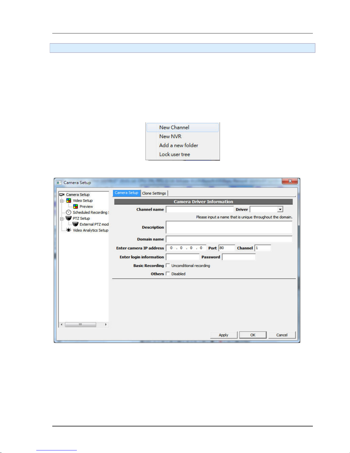
Right-click on the empty area of the user tree panel, and then click "New Channel…"
Following dialog box will appear.
This is an integrated dialog with everything about channel configuration; camera setup, video setup,
schedule recording setup, PTZ setup. Navigate through the tree nodes to change the items to be
configured.
Enter the channel name, IP address, etc information.
Note: "Channel name" is an important signature of a channel and therefore cannot be changed after it's
created. Nor can it be duplicated with other channels. You should choose the channel name carefully, as it
associates all configuration and storage information with that channel. If you expect a more user-friendly
description, you can use the "Description" field for the purpose.
Page 54

Chapter 4. SYSTEM CONFIGURATION
54
4.4.3 Parameters
IP Address
IP address of the network camera
PortThe TCP/IP port number of the network camera
Channel
The channel number of the network camera. This value may apply if a single video server has
multiple channels.
Unconditional Recording
Check this box, if you wish the NVR to start recording immediately. To configure other types of recording,
you need to perform additional operations after channel creation.
Disable Channel
Temporarily disable the channel. NVR will not access any channel with this box checked. You can always
enable it at later time.
4.5 How to add RTSP camera?
4.5.1 Instructions
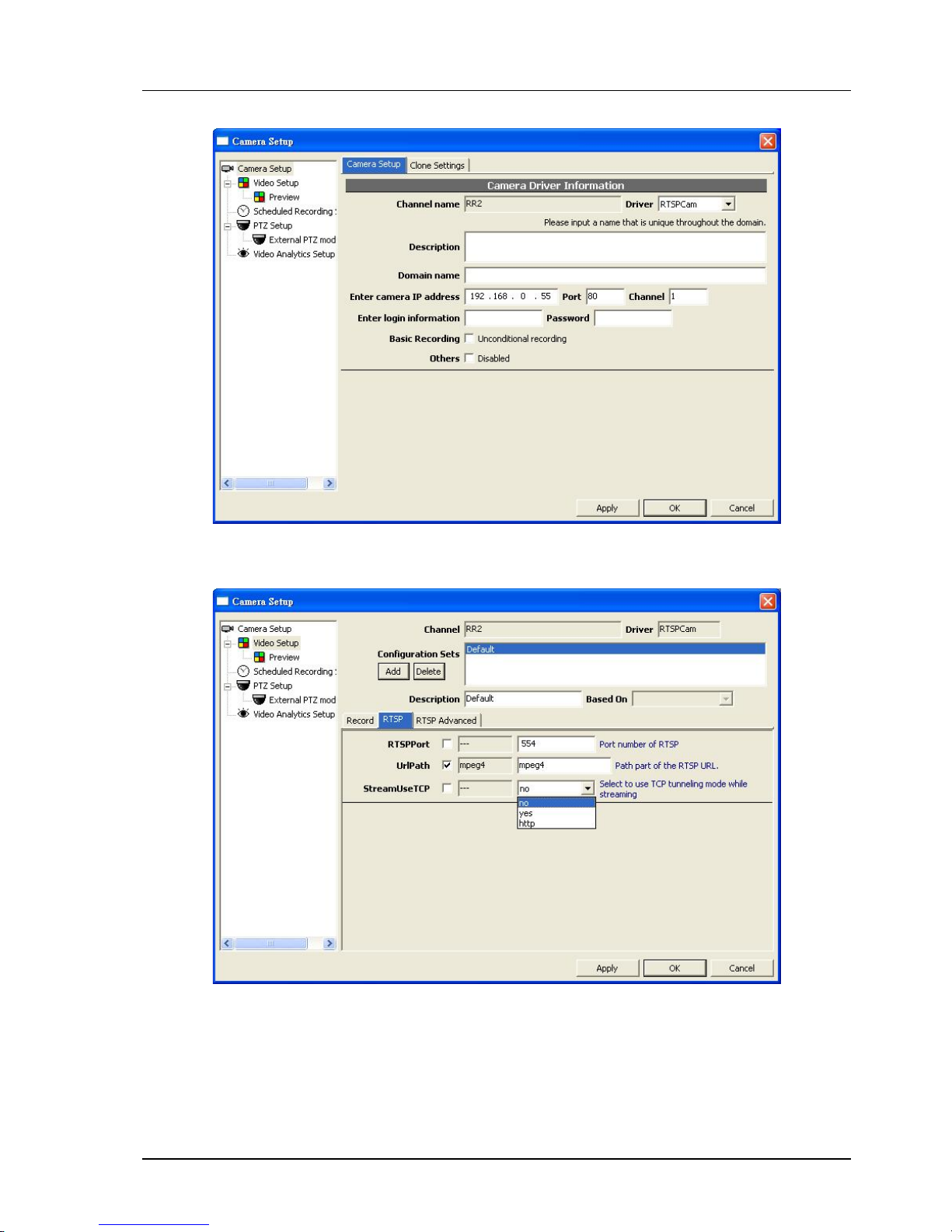
Let's assume you have a RTSP video source as follows: rtsp://192.168.0.55/mpeg4
In this example, you need to perform following configuration steps in Camera Setup
Select RTSPCam as driver
Enter correct IP address (Port is not related RTSP port)
Page 55
Chapter 4. SYSTEM CONFIGURATION
55
Then perform following configuration steps in Video Setup:
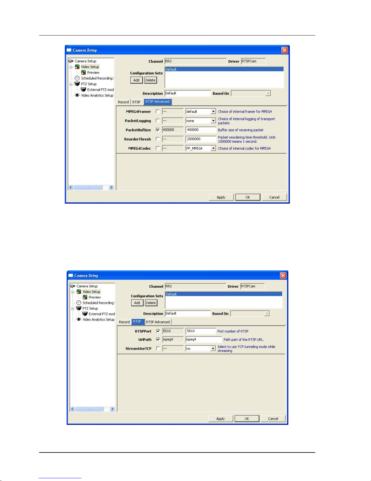
If your frame packet is extraordinarily large, you may needs this step to increase
RTP buffer size (as follows):
Page 56
Chapter 4. SYSTEM CONFIGURATION
56
4.5.2 How to deal with non-standard RTSP port?
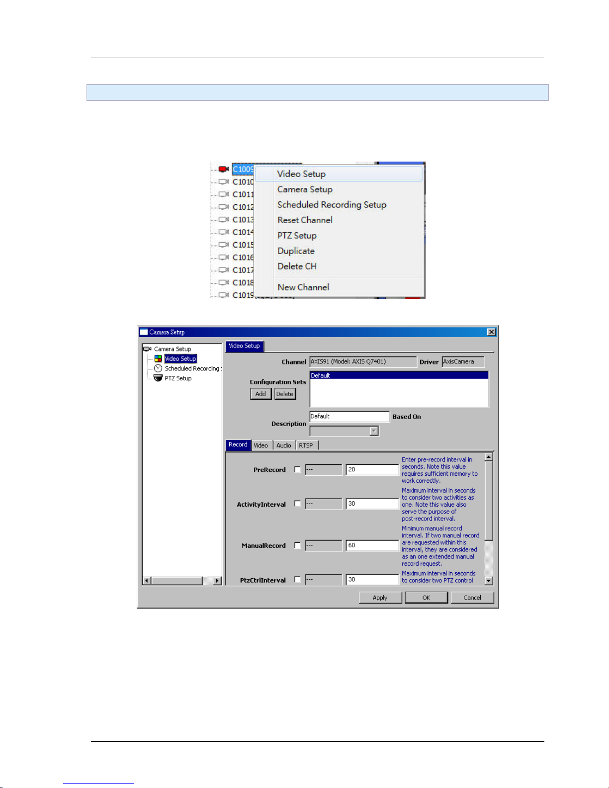
RTSP has a standard control port number 554. If you have a non-standard RTSP control port, your RTSP URL
will look like: rtsp://192.168.0.55:5510/mpeg4
When you encounter this situation, you need to change RTSP Port:
Page 57
Chapter 4. SYSTEM CONFIGURATION
57
4.6 Setting video parameters
4.6.1 GUI overview
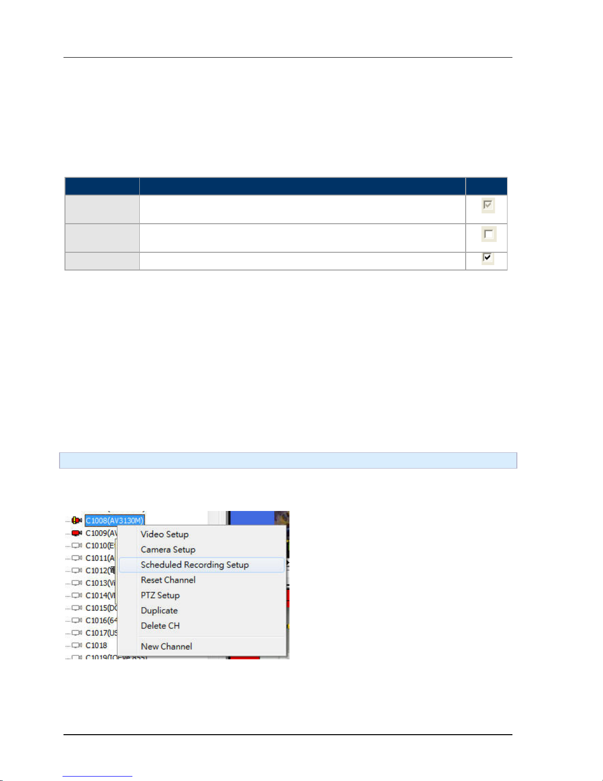
Right-click on the desired channel and select "Video setup".
Following dialog box will appear.
Page 58
Chapter 4. SYSTEM CONFIGURATION
58
4.6.2 GUI overview
Each channel can be associated with multiple set of configurations. A configuration set is composed of
multiple parameters. A configuration set can also "inherit" from another configuration set.
Each parameter, except for its value, can also specify its effectiveness depending on the status of the
checkbox:
Effectiveness Description Icon
Unspecified
The value is not specified in current configuration set. The effective value
depend on the inherited configuration set.
Clear
The value is "cleared" by current configuration set, meaning the
parameter will not be in the effective parameter list.
Set The value is set by current configuration.
Carefully planning of configuration set can make your system extreme versatile to deal with various
different situations. Especially note that the schedule config can associate to a specific configuration set.
The meaning of each parameter can differ from various vendors of IP cameras. You can refer to the
description beside the parameter or look for vendor manuals for further information.
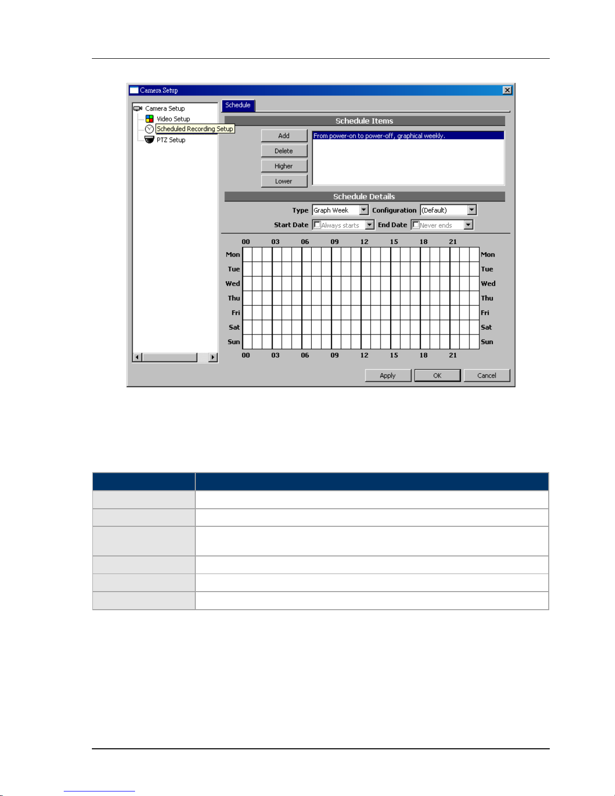
4.7 Schedule configuration
4.7.1 GUI overview
Page 59
Chapter 4. SYSTEM CONFIGURATION
59
4.7.2 Configuration
Scheduled configuration items has various types, including whole day, daily, weekly (detailed), weekly
(graphic), disabled. You may add multiple items.
Type Description
24x7 24 hours recording
Dail Daily fixed interval . For example: daily 08:00:00 to 21:30:00.
Weekly (Detailed)
Resembles "Daily", but you may appoint to days within a week. For example:
Every Monday, Wednesday, Friday 08:00:00 to21:30:00
Weekly (Graphic) Weekly schedule. Each slot is united an hour.
Interval Fixed interval, each starts with offset every X seconds, lasts Y seconds
Disabled Disable current schedule item.
Page 60
Chapter 4. SYSTEM CONFIGURATION
60
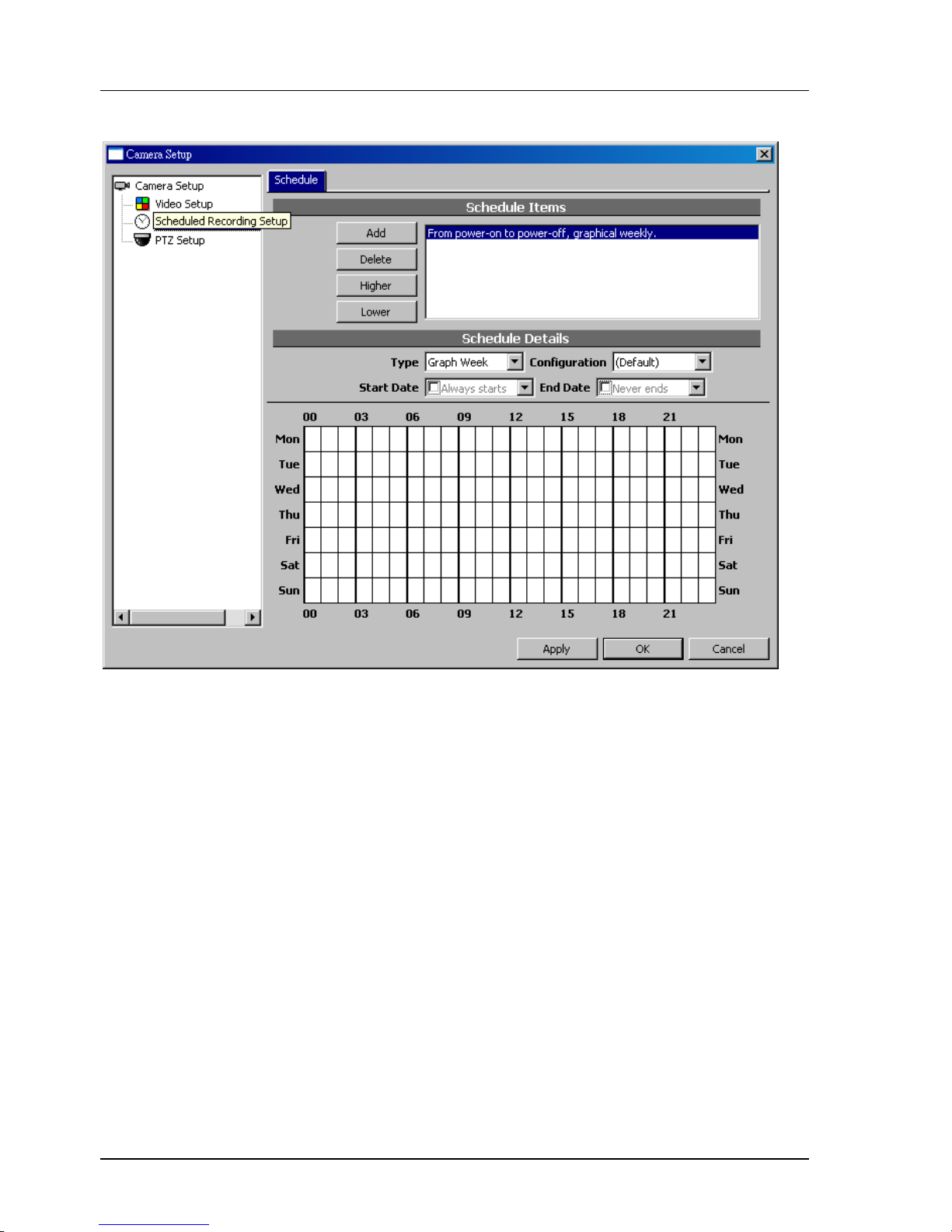
4.7.3 Weekly (Graphic) Schedule Configuration
Horizontal axis is time, with hour as the unit. Vertical axis is day in a week. Click to change the schedule
status. Blue means enabled, white means disabled. Click any cell and drag will copy the state of the clicked
cells to others.
Page 61
Chapter 4. SYSTEM CONFIGURATION
61
4.7.4 Scheduled Video Configuration
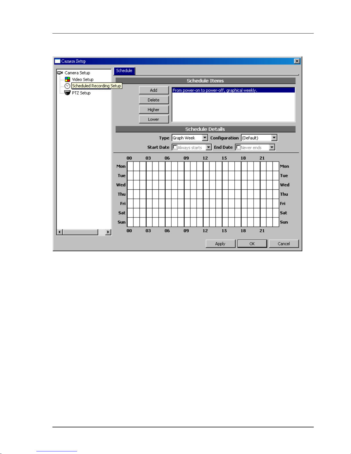
You may specified a Video Parameters for each schedule configuration item . When that item is activated
during appropriate time, the specified parameter will be used. If you choose (Default) for the value,
schedule configuration will not affect video parameters.
When multiple schedule configuration item is in effect, the higher (in order) one will apply. To change the
priority of the items, use Higher and Lower buttons.
Page 62
Chapter 4. SYSTEM CONFIGURATION
62
4.8 Permission control overview
4.8.1 Concepts
The permission control in CTC Union NVR is group-based. The administrator configures permissions for
groups, and then assigns the user to one or more groups. Permissions are not assigned directly to the user,
but rather associates to the user through groups.
4.8.2 Permission Types
System admin
Allows to control system-level configuration, such as permissions or
creating a channel.
System operation Allows creating or deleting a channel, editing maps and files.
All channel permissions Configures permissions to all channels.
Specific channel permissions Configures permissions to specific channels.
Channel live video Allows to view live video
Channel playback Allows accessing archived (playback) video.
Channel operation Allows to operate on PTZ, manual recording, or channel resetting.
Channel administration Allows to change settings.
4.9 Adding a user
4.9.1 GUI overview
Following dialog box will appear. Please click on Users tree node.
If you want to create, delete, or duplicate a user, use the buttons on the top area.
Page 63
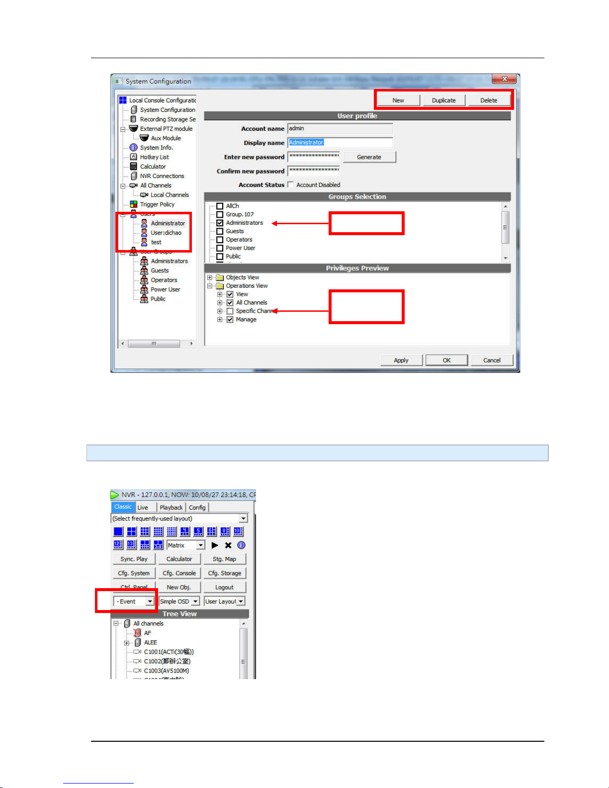
Chapter 4. SYSTEM CONFIGURATION
63
4.10 Adding a group
4.10.1 GUI overview
Following dialog box will appear.
Select Group
Preview
privilleges
Page 64
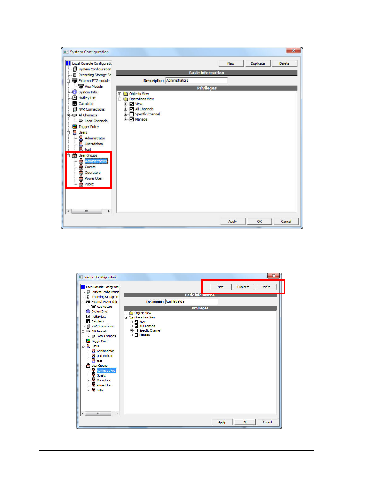
Chapter 4. SYSTEM CONFIGURATION
64
You can check the privillege you wish to grant to the group.
If you want to create, delete, or duplicate a user group, use the buttons on the top area.
Page 65
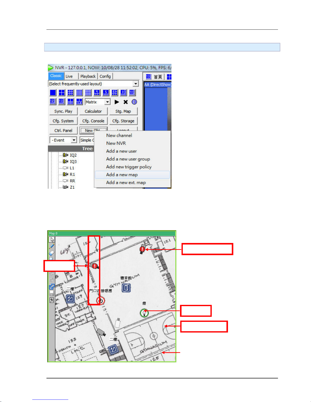
Chapter 4. SYSTEM CONFIGURATION
65
4.11 Creating Maps
4.11.1 Create New Map
Select Add a new map in menu of New Obj. The map can be dragged into User tree and be operated as it
is in system briefcase viewer. To view the map, drag it in a player. Not all players support maps.
4.11.2 GUI overview
I/O port
Disable channel
Tool bar
Channel in alarm
Page 66
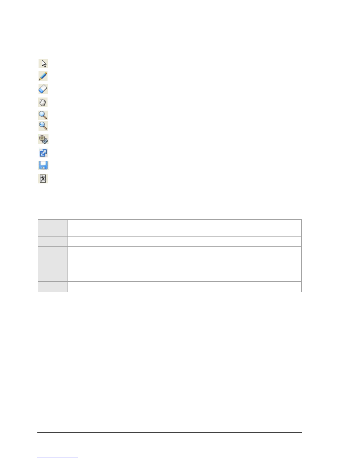
Chapter 4. SYSTEM CONFIGURATION
66
4.11.3 Toolbar Functions
Enter map viewing mode
Enter map editing mode
Enter delete object mode
Enter map panning mode
Zoom-in map
Restore 1:1 view of map
Map properties
Map hyperlink
Save changed map
Exit map editor
4.11.4 Adding Items
Bitmap
Drag a JPEG/BMP file in the map. Or drag a previously uploaded file from system briefcase
viewer.
Channel Drag channels from system briefcase viewer or user tree.
Hyperlink
Assuming you want to add the link of map A in map B.
1. Open both map A and map B in players.
2. Adjust the view of map A with zoom in/out.
3. In the toolbar of map A, drag Map hyperlink icon to map B.
IO port Drag IO ports from system briefcase viewer or user tree.
Page 67
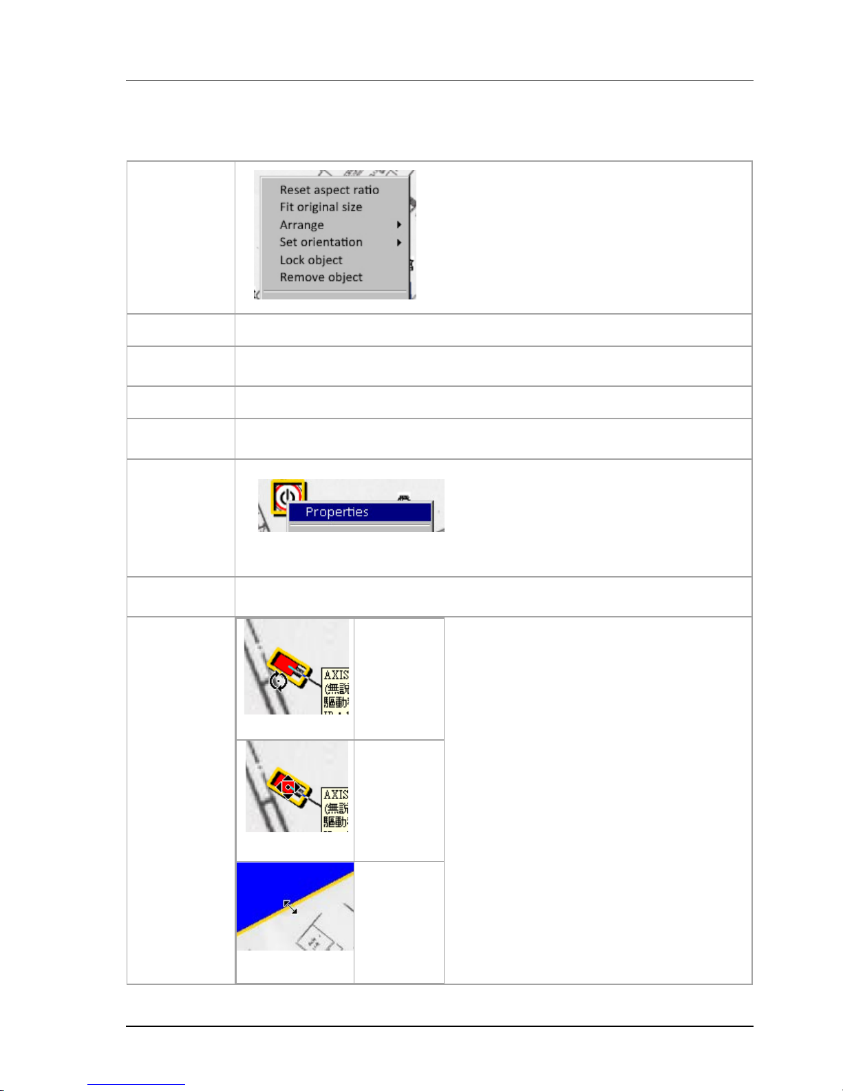
Chapter 4. SYSTEM CONFIGURATION
67
4.11.5 Basic Operations
Not all operations are available for all objects.
Reset aspect
ratio
Reset the object to its original aspect. Only applies to
Bitmaps.
Fit original
size
Reset the object to its original size. Only applies to Bitmaps.
Arrange
Arrange the object's display order(Z order). "Back" objects covered by "front"
objects are not visible.
Set
orientation
Set orientation of the object to 0/90/180/270 degrees.
Lock object
Position/size/direction of a locked object cannot be changed. Its "property" dialog is
still accessible if available for that object type.
Properties
Invoke the property dialog to edit additional information such as description or
stereotype(icon). Only applies to hyperlink and IO port.
Remove
object
Only the map object is deleted. The entity the object represents to will not be
deleted.
Mouse
operations
Rotate/resize
Move
Resize
Page 68
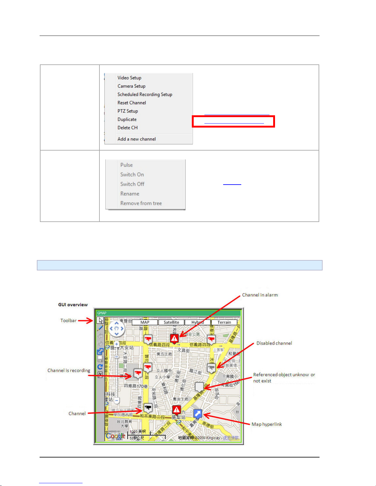
Chapter 4. SYSTEM CONFIGURATION
68
4.11.6 Special operations
4.12 External Maps
4.12.1 Create New Map
Channel operation
See also :
●
Setting video parameters
●
Schedule configuration
IO port
See also IO Port
Page 69
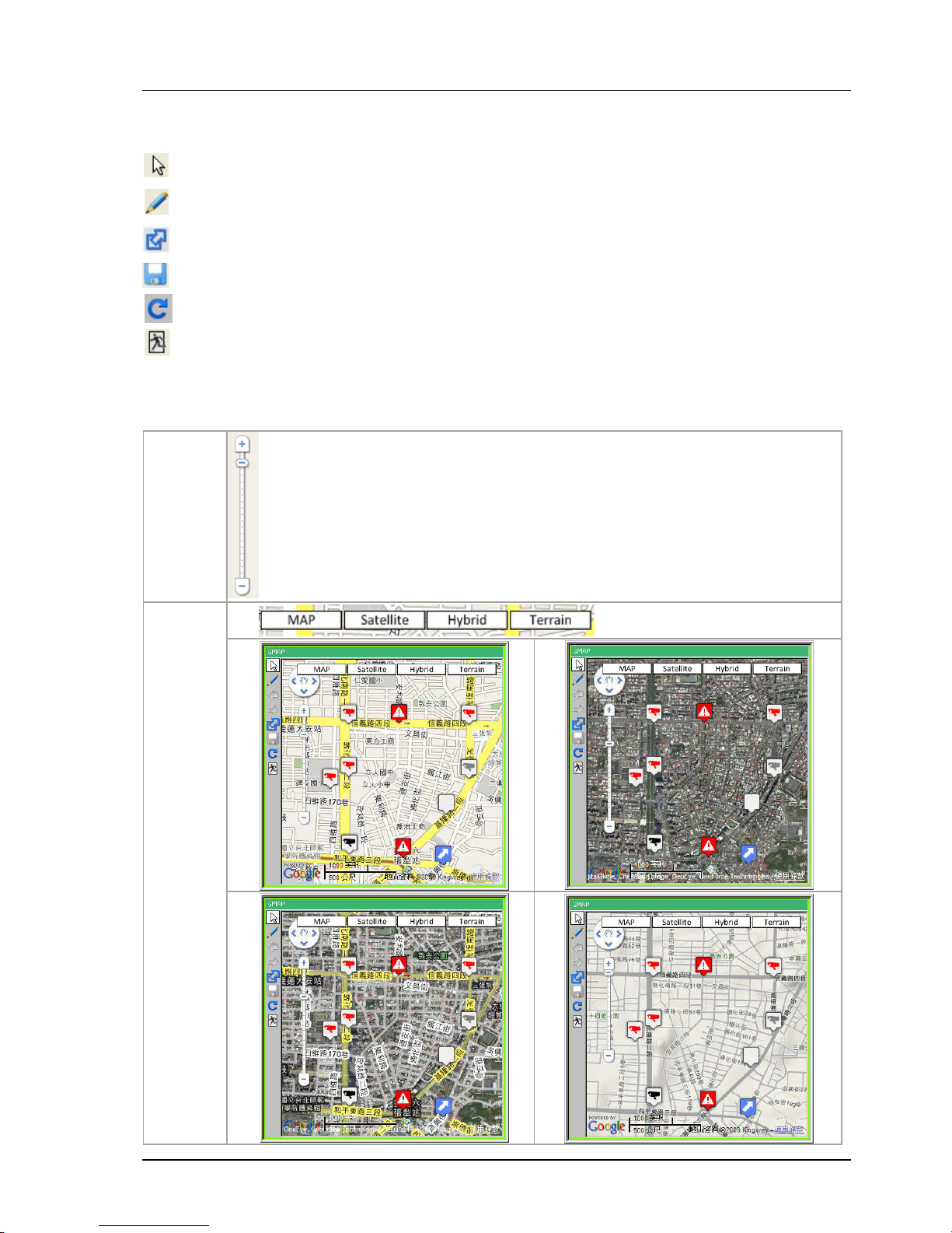
Chapter 4. SYSTEM CONFIGURATION
69
4.12.2 Toolbar Functions
Enter map viewing mode
Enter map editing mode
Added a bookmark of current map and current view in system briefcase.
Save changed map
Reloading the map from map server. Any unsaved changes will be discarded.
Exit map editor
4.12.3 Basic Operations
Zoom In
Use mouse wheel or click the scale bar on map.
Change
Map
Type
Page 70
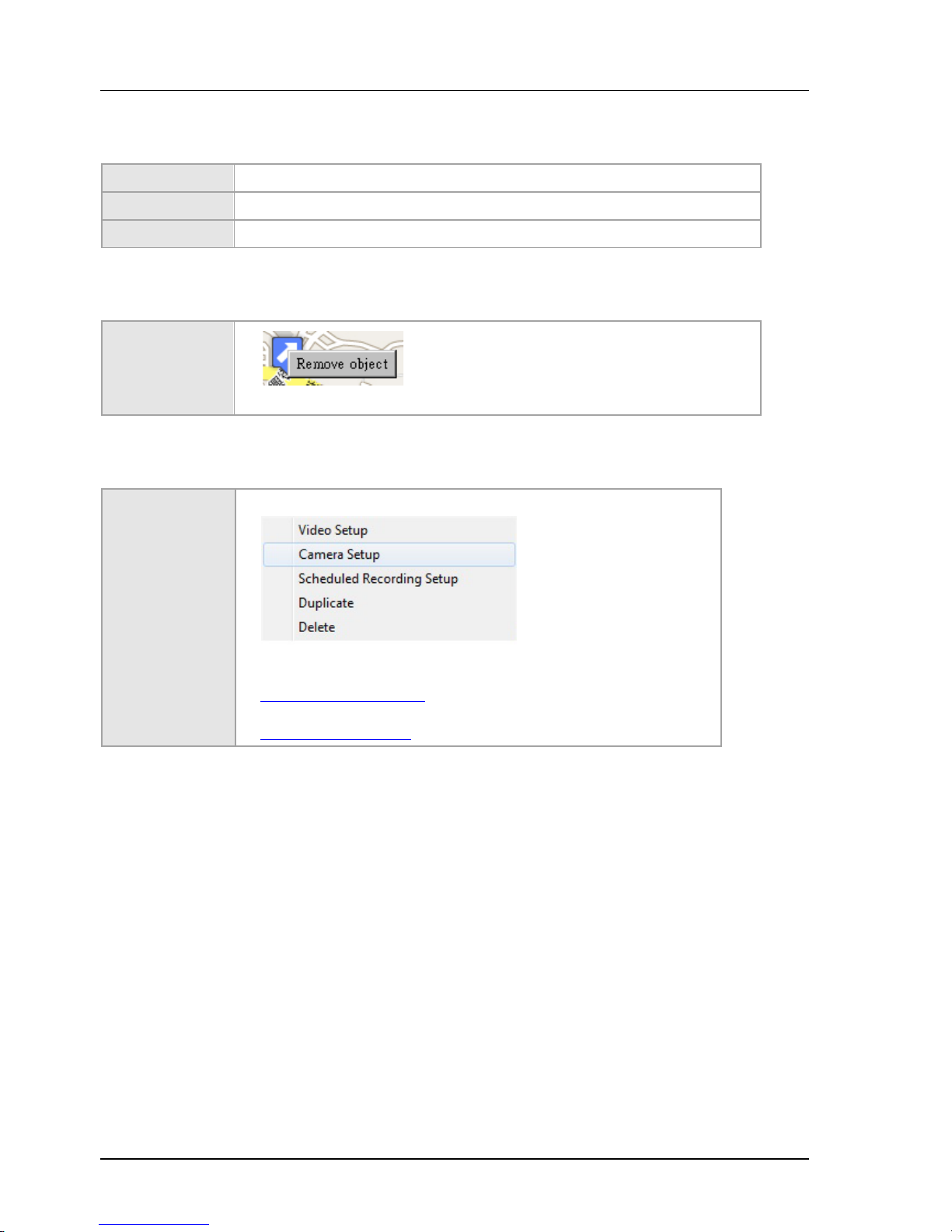
Chapter 4. SYSTEM CONFIGURATION
70
4.12.4 Adding Items
Channel Drag channels from system briefcase viewer or user tree.
Hyperlink Drag a map hyperlink from briefcase viewer or from internal map viewer.
IO port Currently unsupported
4.12.5 Basic Operations of Objects
Remove object
Object can only be removed in editing mode.
4.12.6 Special operations
Channel operation
See also
Setting video parameters
Schedule configuration
Page 71
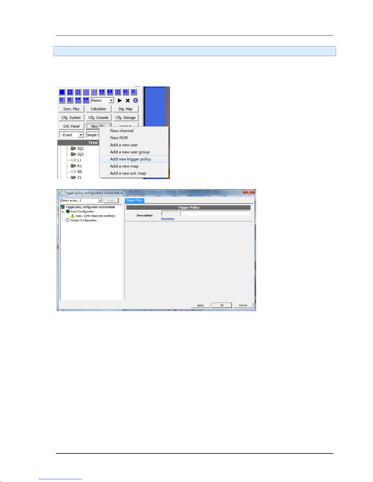
Chapter 4. SYSTEM CONFIGURATION
71
4.13 Trigger Policy
4.13.1 Adding New Trigger Policy
Click New Obj and select "Add trigger policy". If multiple trigger policies exists in a system, they are all ineffective.
Page 72

Chapter 4. SYSTEM CONFIGURATION
72
4.13.2 Input Configuration
Channel trigger Triggered by channel events such as video loss, alarm, IO port... etc.
System trigger System events such as system start, system config change... etc.
Schedule trigger Triggered at specified time.
4.13.3 Output Configuration
Channel control Recording, IO control, PTZ control
Email Send Emails
FTP Upload file to FTP server
4.13.4 Channel trigger
on IO on
off IO off
vloss video los
vreturn video recovered
disabled disabled
enabled enabled
record is/start recording
nrecord not/stop recording
alarm alarm triggered
alarm_progress alarm in progress
nalarm alarm dismissed
4.13.5 Schedule trigger
See also Schedule configuration
4.13.6 System trigger
any_vloss any video loss
system_start system start
error_restart system start after error shut down
system_config_change system config changed
channel_config_change any channel config changed
Page 73
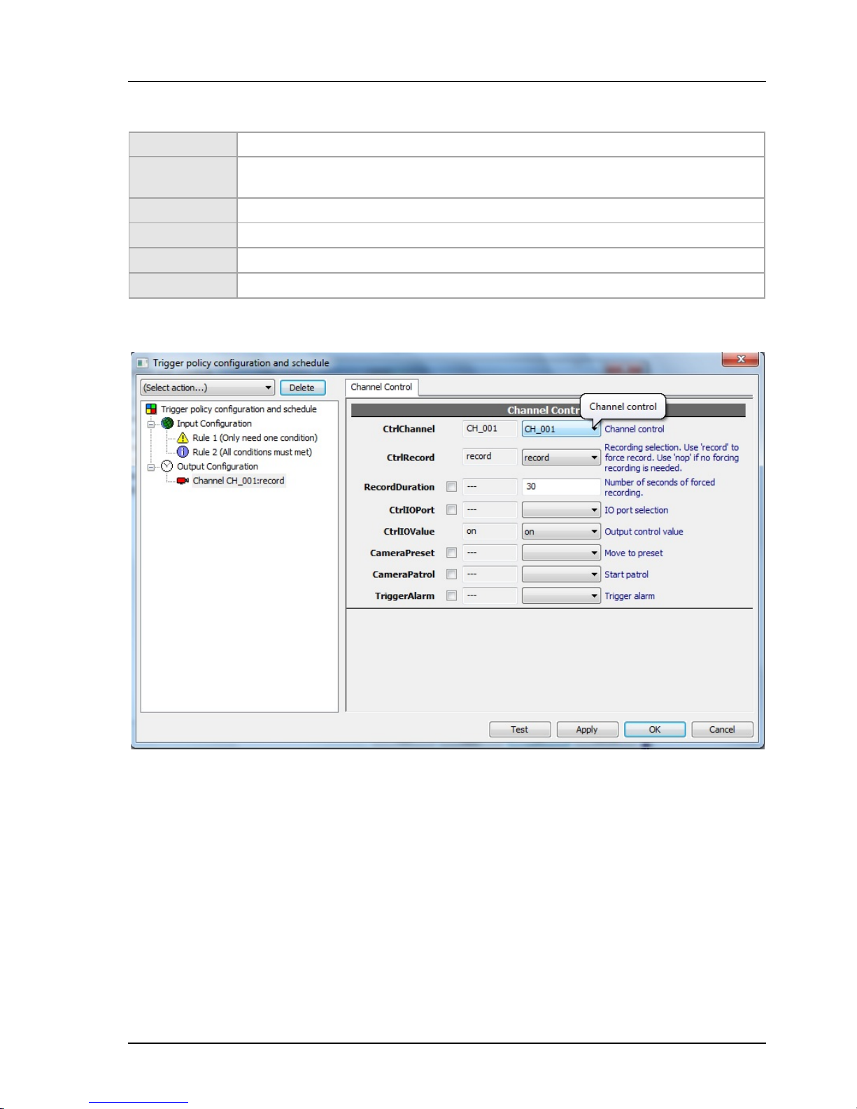
Chapter 4. SYSTEM CONFIGURATION
73
4.13.7 Channel control
CtrlChannel The channel to control
CtrlRecord
Recording selection. Use 'record' to force record. Use 'nop' if no forced recording is
needed.
RecordDuration Number of seconds of forced recording.
CtrlIOPort IO port selection
CtrlIOValue Output control value
CameraPreset Move to preset
Page 74
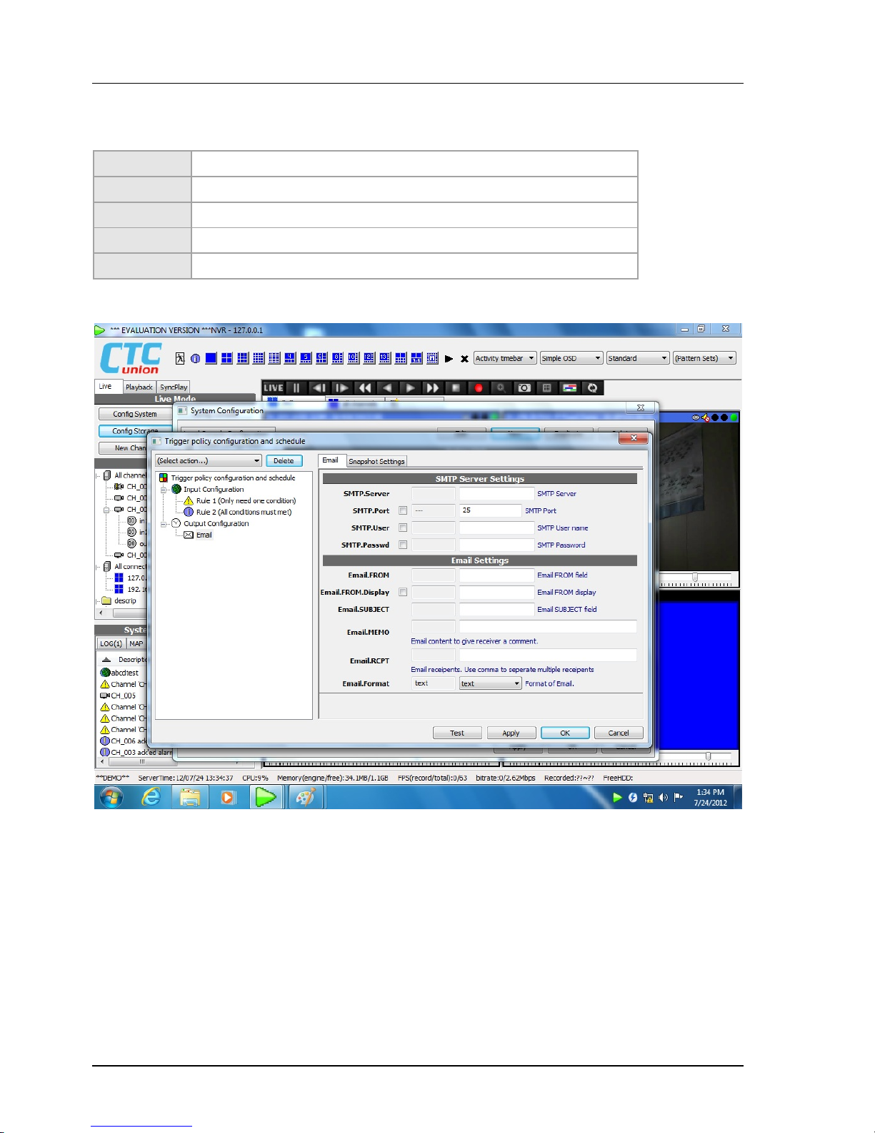
Chapter 4. SYSTEM CONFIGURATION
74
4.13.8 Email
Required parameters
SMTP.Server IP or domain name of SMTP server
SMTP.Port Port, usually 25
SMTP.User User name to log in
SMTP.Passwd Password to log in
Email.RCPT Recipients. At least one is required. Separate multiple recipients with.
Page 75
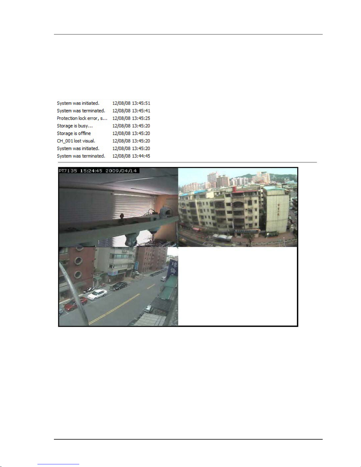
Chapter 4. SYSTEM CONFIGURATION
75
4.13.9 Snapshot
If "Email.Format" is set to "snapshot" and one or more channel control exist in this policy, a snapshot of
the channels is attached to the email. Multiple channels will be composed as a single snapshot
automatically. The dimension and quality of the snapshot can be configured in Snapshot Settings tab.
Page 76
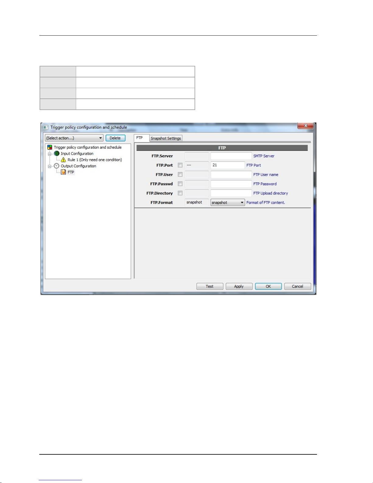
Chapter 4. SYSTEM CONFIGURATION
76
4.13.10 FTP
Required parameters
FTP.Server IP or domain name of FTP server
FTP.Port Port, usually 21
FTP.User User name to log in
FTP.Passwd Password to log in
4.13.11 Trigger policy logics
Multiple trigger conditions can exist in a single trigger rule. Action is done only when all or some of the
conditions are met, depends on AND or OR logic being applied. Logic OR is always applied to the first rule.
Logic AND is applied to any added new rule.
Page 77
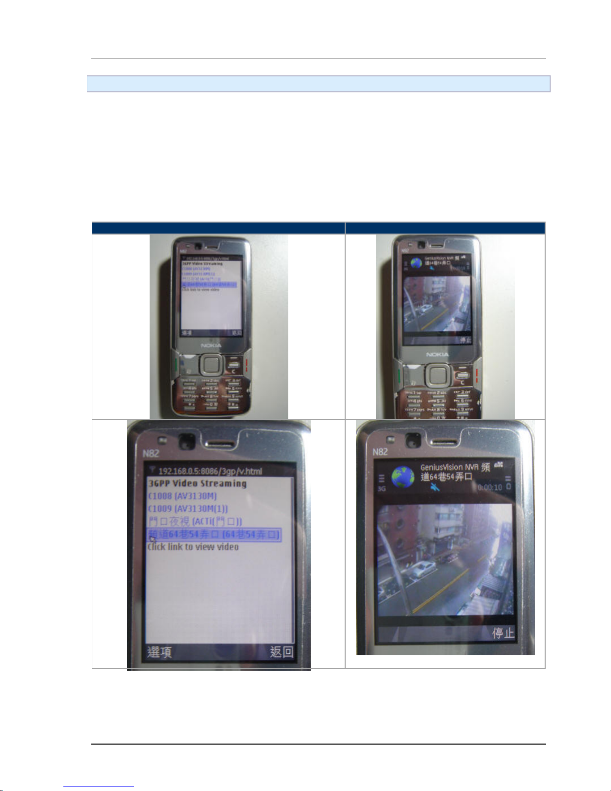
Chapter 4. SYSTEM CONFIGURATION
77
4.14 Mobile Phone Video Streaming (3GPP)
4.14.1 Overview
If you have a mobile phone that is compliant to 3GPP standard, then you can now use it to connect to our
NVR to see live video streaming.
If your system is properly configured to support 3G video streaming, you will firstly use your browser to
enter the URL to your NVR in the form:
Note: The "8086" is the default port number of the NVR built-in web server, the one that also serve
Internet Explorer. This can be changed from system configuration.
Step 1. Entering first page, listing all channels available
Step 2. Viewing video streaming
Page 78
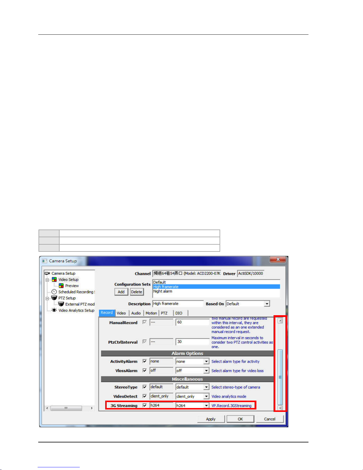
Chapter 4. SYSTEM CONFIGURATION
78
4.14.2 How-to's
Here's a of list quick questions that might help you to find the information you need:
Is the 3G video streaming default enabled?
How to enable 3G video streaming?
Why can't I see 3G video streaming?
How to change default web server port number?
What are the frame-rate or image size of the 3G streaming video? Can they be changed?
4.14.3 Is the 3G video streaming default enabled?
No.
3G video streaming involves potential video transcoding. It has to be enabled in the server before you can
really use it. Also, be informed that enabling this feature consumes certain resource (though not much) on
the server.
4.14.4 How to enable 3G video streaming?
To enable 3G video streaming, open "Video Setup" of a designated channel. On first tab "Record", scroll
down the page to look for attribute "3G Streaming".
There are three options:
off
3G video streaming is disabled.
on
Turn on the 3G video streaming, using MPEG-4 codec.
h264
Turn on the 3G video streaming, using H.264 codec.
Page 79
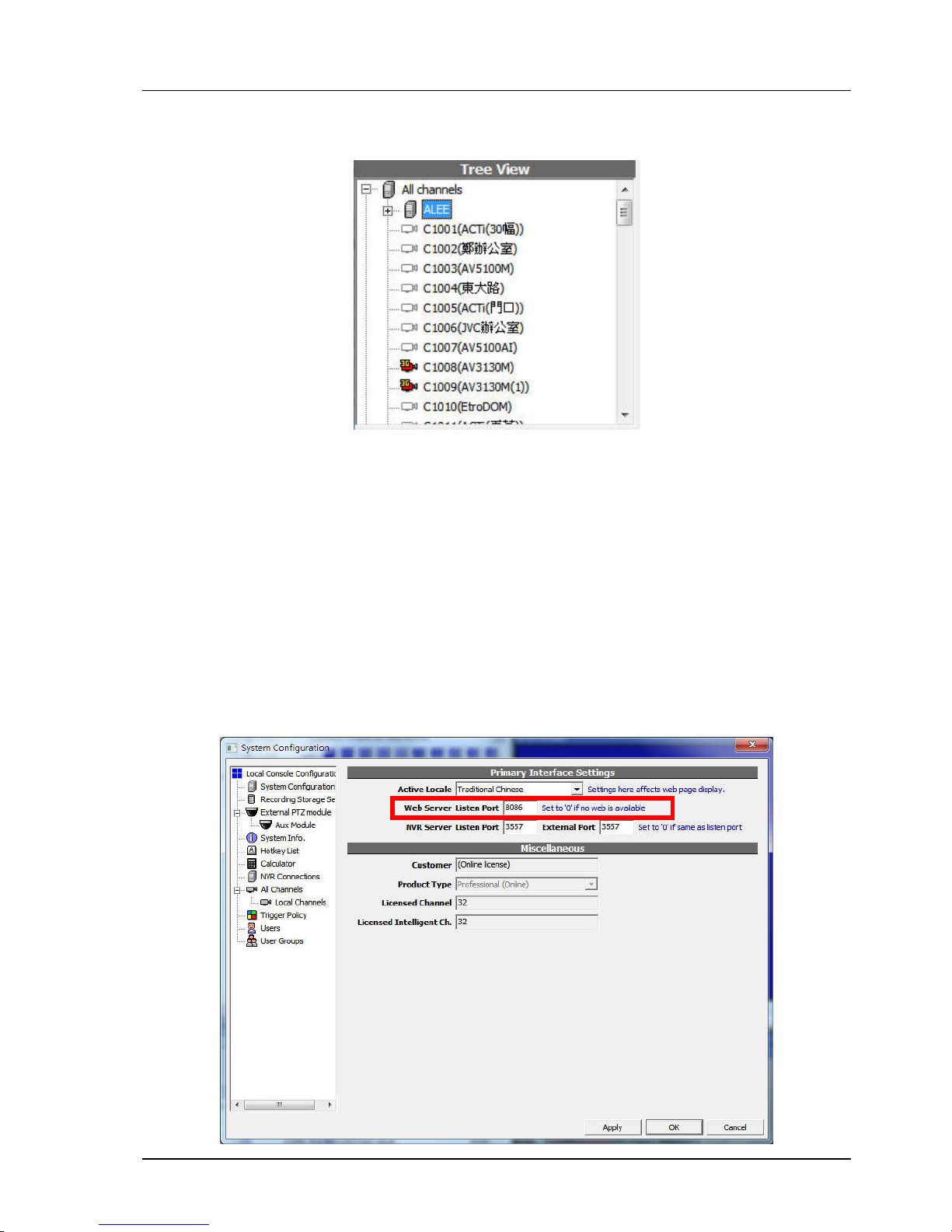
Chapter 4. SYSTEM CONFIGURATION
79
If the 3G video streaming is successfully enabled, a small "3G" will appear beside the camera icon,
indicating 3G transcoding is activated:
4.14.5 Why can't I see 3G video streaming?
There could be a number of reasons. Firstly, your mobile phone must support 3GPP standard for
this function to work. Secondly, when the mobile browser tries to reach NVR web server, it will
automatically determine the phone type. If this detection is not successful, you may not be
redirecting to the correct page. In this case, enter the following URL:
http://<ip_to_your_nvr>:8086/3gp/v.html
If you still can't see video streaming, please contact our technical support, with your mobile
phone model number (or device) available to us for testing and diagnosis.
How to change default web server port number?
Invoke "Cfg. System" dialog and change the value as indicated in the following picture:
Page 80

Chapter 4. SYSTEM CONFIGURATION
80
4.14.6 What are the frame-rate or image size of the 3G streaming video? Can they be changed?
The image size and frame-rate is currently fixed at 320x240, 5 frames-per-second.
There is currently no GUI offered to change these settings. You can only choose to enable this feature or
not.
Page 81
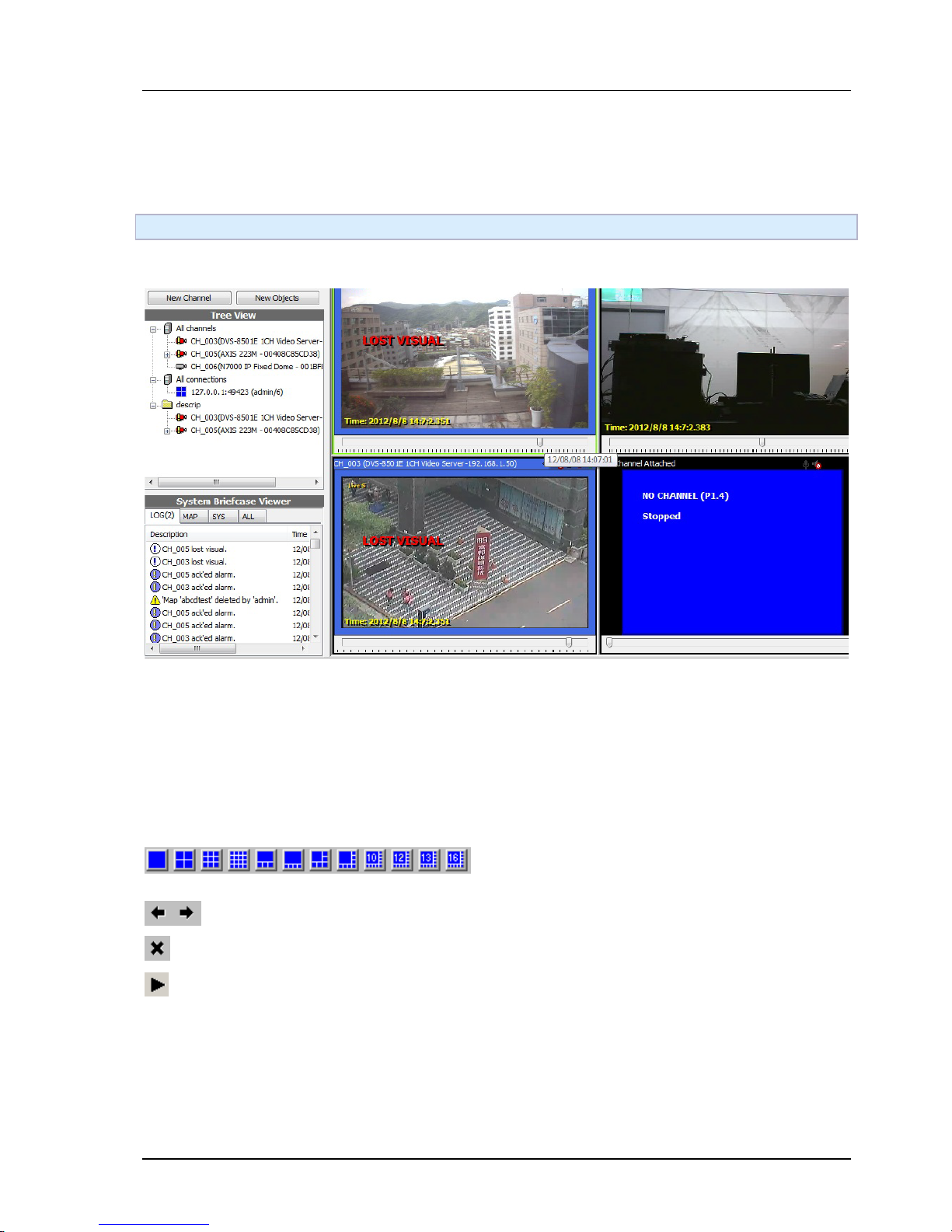
Chapter 5. NVR SYSTEM OPERATION
81
Chapter 5.
NVR SYSTEM OPERATION
5.1 Console Overview
5.1.1 GUI Overview
5.1.1.1 Layout Control
Switch between the pre-defined NxN or special layouts.
Previous/next page.
Stop all players.
Make all players show live.
Page 82
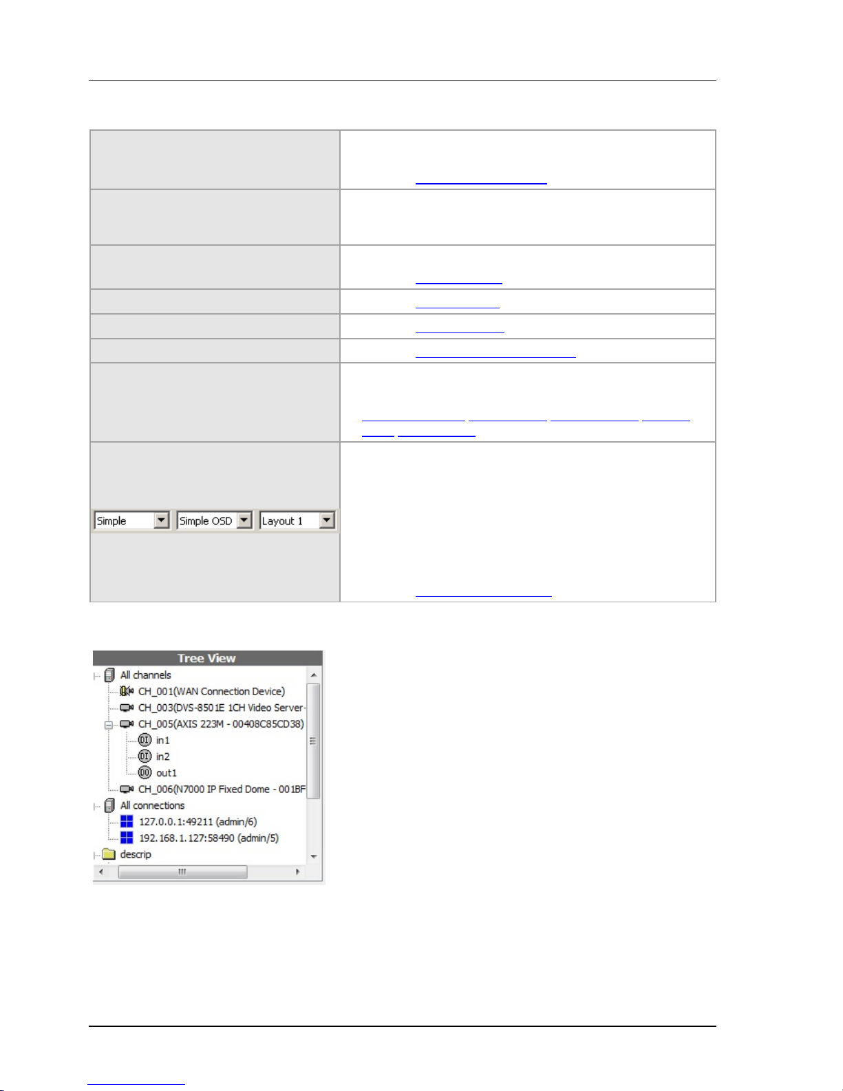
Chapter 5. NVR SYSTEM OPERATION
82
5.1.1.2 System control
Sync. Play
Synchronize all players. When the button is sinked, playback
control of all players are synchronized.
See Also Synchronized playback
Logout
Log out. The local console will be closed but the system is
not terminated. You will need to enter account/password to
operate the system.
Calculator
Opens various configuration or tool dialogs.
See Also User calculator
Stg. Map See Also Storage report
Cfg. System, Cfg. Console See Also Console setting
Cfg. Storage See Also Configuration video storage
New Obj.
Add a new channel, user, group, map..., etc.
See Also
Adding a channel
Adding a user Adding a group Creating
Maps Trigger Policy
From left to right respectively:
Toolbar type selector:
Set the default toolbar for all players. This overrides all
individual players' toolbar settings.
OSD type selector:
Select OSD information level for all players.
Main layout selector: Select default console layout type.
See Also Using playback timeline
5.1.1.3 User tree
User can manage objects by creating folders and drag & drop to change the hierarchy and the order.
Folders can also be renamed. Remind that the tree is global and local changes affect all remote GVNVR
connected.
The node "All channels" are pre-defined and cannot be modified. Dragging a channel in "All channels" to a
user-created folder creates its representatives which can be operated like the original channel item. But
deleting a representative doesn't remove the channel from the system.
See Also Building user tree
Page 83
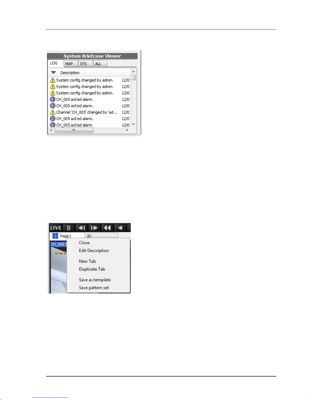
Chapter 5. NVR SYSTEM OPERATION
83
5.1.1.4 System briefcase viewer
A system briefcase viewer let the users browse system objects like user logs, channels, maps, users,.. etc.
There are three components in system briefcase viewer; the filter, the header, and the list. The filter
controls what types of items to be displayed. The header can be clicked to sort the items by different
columns and different order. Right-click on different types of objects invokes their corresponding context
menus. Items may also be dragged into players. Drag & drop behavior depends on the destined player state
and the item type.
See Also Viewing logs
5.1.1.5 Pattern tab control
User can create and rename tabs in pattern tab control. Each pattern tab has its own layout and state.
See Also Managing layout pages
Page 84
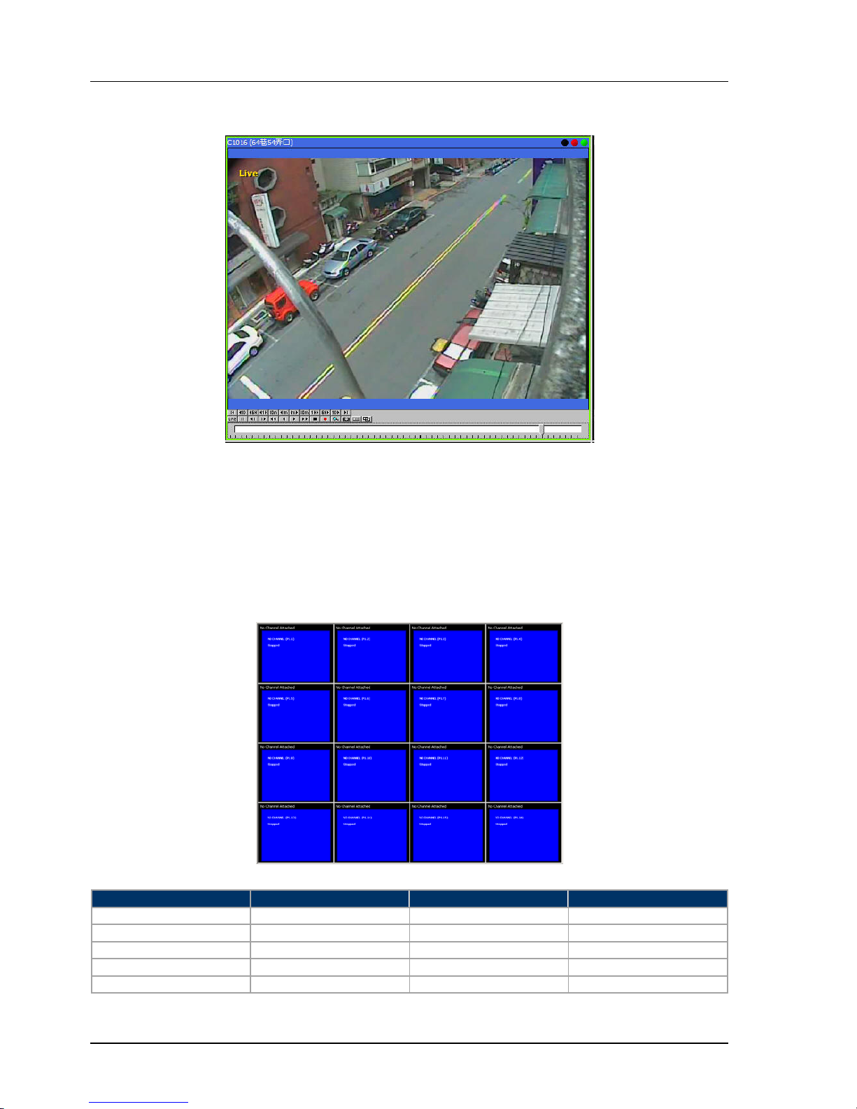
Chapter 5. NVR SYSTEM OPERATION
84
5.1.1.6 Player
There are three components in the payer; status bar, display, and toolbar. Status bar shows the title of the
channel attached and its states. The three indicators on the top-right shows if the channel is recording (red),
accessing recorded data(yellow), live video(green), or alarm. The toolbar is used to control the player.
See Also Player
Player (Multi-Function-Display) Capabilities
Each player slot in the console has an number as their identifier. Those are P1.1, P1.2.. P1.16, etc, as
illstrated below. Their function is slightly different, as illustrated in the table following the picture.
Player identifier
Can play live & PB?
Can view maps
Can view Ext. Map
P1.1
Yes
Yes
Yes
P1.2
Yes
Yes
No
P1.3
Yes
Yes
No
P1.4
Yes
Yes
No
P1.5 ... P1.25
Yes
No
No
Page 85
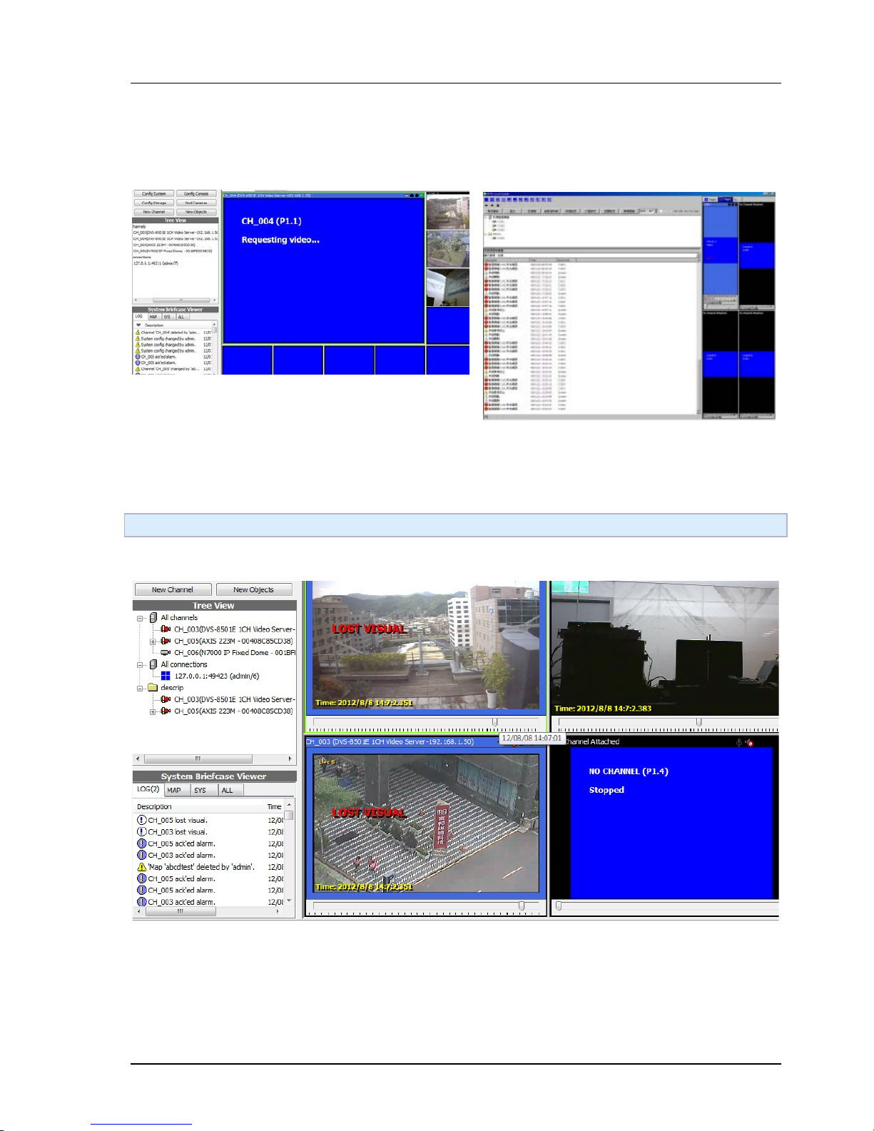
Chapter 5. NVR SYSTEM OPERATION
85
5.1.1.7 Splitter Control
Hover mouse on these areas and the cursor will be changed to a two-way arrow. Users can hold left button
and drag to adjust the size of different console components.
5.2 Viewing live video
5.2.1 GUI Overview
Before viewing live video, a channel must be attached to a player. To attach a channel, drag it from user
tree(the red box above) to a player(the blue area above). Or double click to auto assign it to an available
player.
Page 86
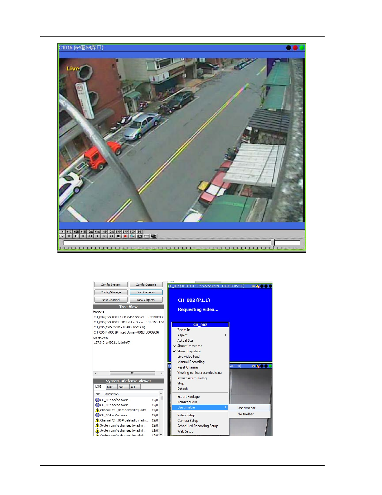
Chapter 5. NVR SYSTEM OPERATION
86
To switch from playback to live video, click LIVE (the left most) in the toolbar. Or when the player is
focused, press ENTER on keyboard to view live video. Players can be focused by left mouse click on it. You
can tell if a player is focused by a green frame around it.
If you cannot see any buttons in players, use the context menu of the player to set the toolbar.
Page 87
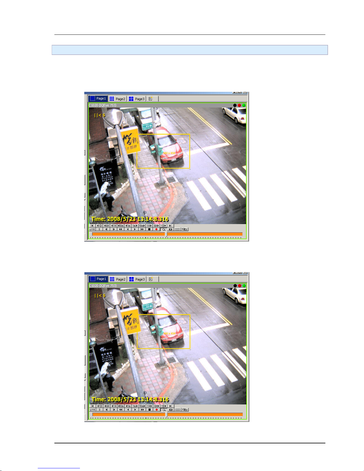
Chapter 5. NVR SYSTEM OPERATION
87
5.3 Digital PTZ
5.2.1 Digital Pan-Tile-Zoom
User can right-click context menu and select "Zoom-In" to drag a rectangular area to zoom-in.
Step 1. Click on the magnifier icon on the player toolbar.
Step 2. Drag to select a rectangular area.
Page 88
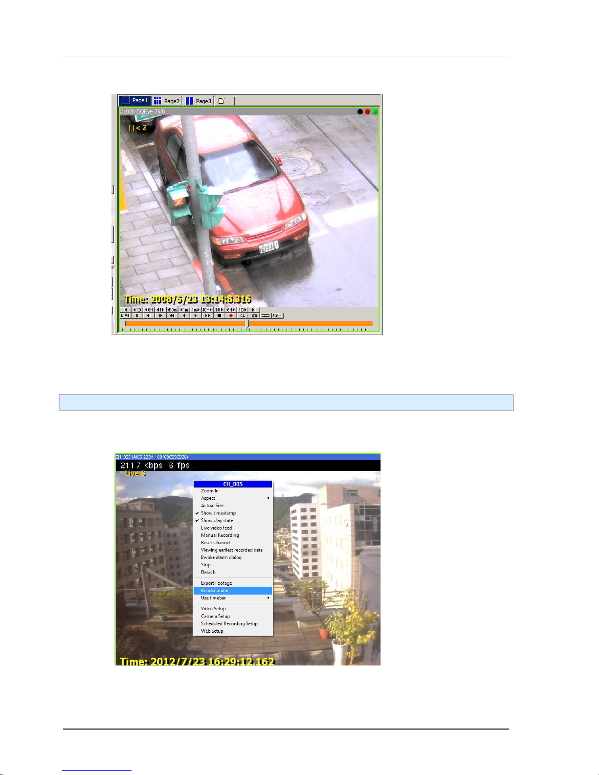
Chapter 5. NVR SYSTEM OPERATION
88
Step 3. Zoomed-in.
Under the zooming mode, user can hold mouse left button down to pan the zoomed area. User can also
use mouse-wheel to easily zoom-in and zoom-out interested area quickly.
5.4 Rendering audio
5.4.1 GUI Overview
In the context menu of players, click "Render audio" to enable audio. To mute the channel, just click it
again. Or click on the speaker icon.
Page 89
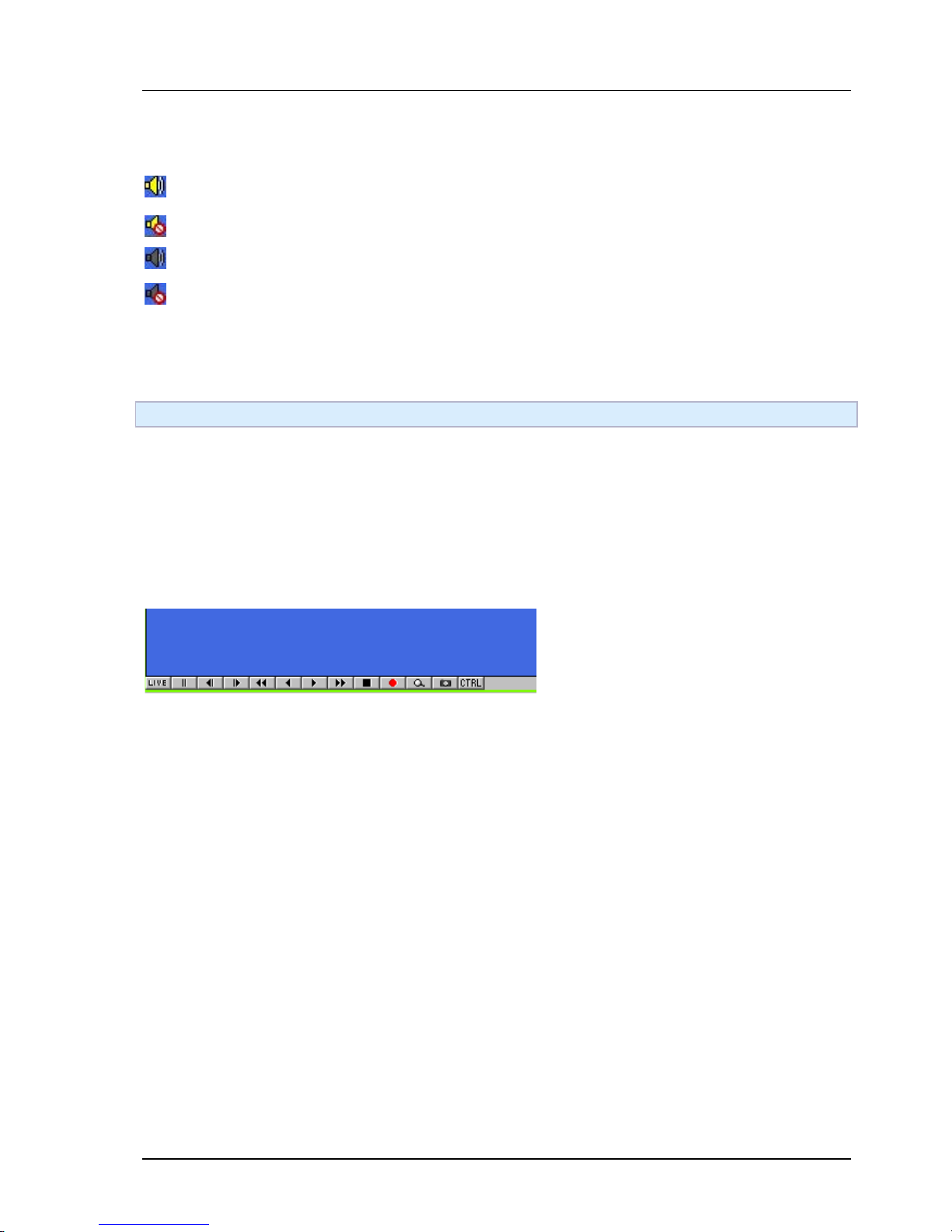
Chapter 5. NVR SYSTEM OPERATION
89
5.4.2 Audio Icon Explained
The channel has audio, and is currently playing.
The channel has audio, but not playing.
Though audio playing is requested, but no audio is available.
Audio playing is neither requested nor available.
5.5 Viewing playback video
5.5.1 Concept
There are several methods to view playback video. You can:
1. Use the toolbar in player. It works just like the buttons on a CD/DVD player.
2. Use player control panel.
3. Use the time bar in player.
4. Use the storage report.
5. Hot keys
5.5.2 Simple toolbar
Live view
Pause
Fast backward 2x/4x/8x
Backward playback
Forward playback
Fast forward 2x/4x/8x
Stop
Manual recording
Zoom in
Take snapshot
Open control panel
Page 90
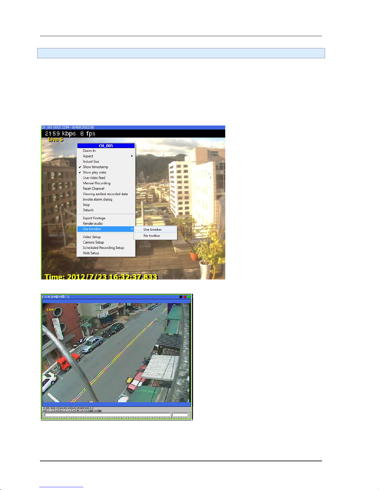
Chapter 5. NVR SYSTEM OPERATION
90
5.6 Using playback timeline
5.6.1 Overview
A timeline is an integrated tool for both inspecting recorded data and navigating in video playback. The
timeline can be configured to show different information of recorded data. User can access the desired
data easily based on the information the timeline provides.
5.6.2 Using timeline
Timeline can be enabled in player context menu.
Before timeline can be operated, it must acquire window focus first. To do so, left click on the timeline and
a dotted box appeared around the timeline. The user can use the mouse wheel to zoom in or zoom out the
timeline. The ruler indicates the scale.
Page 91
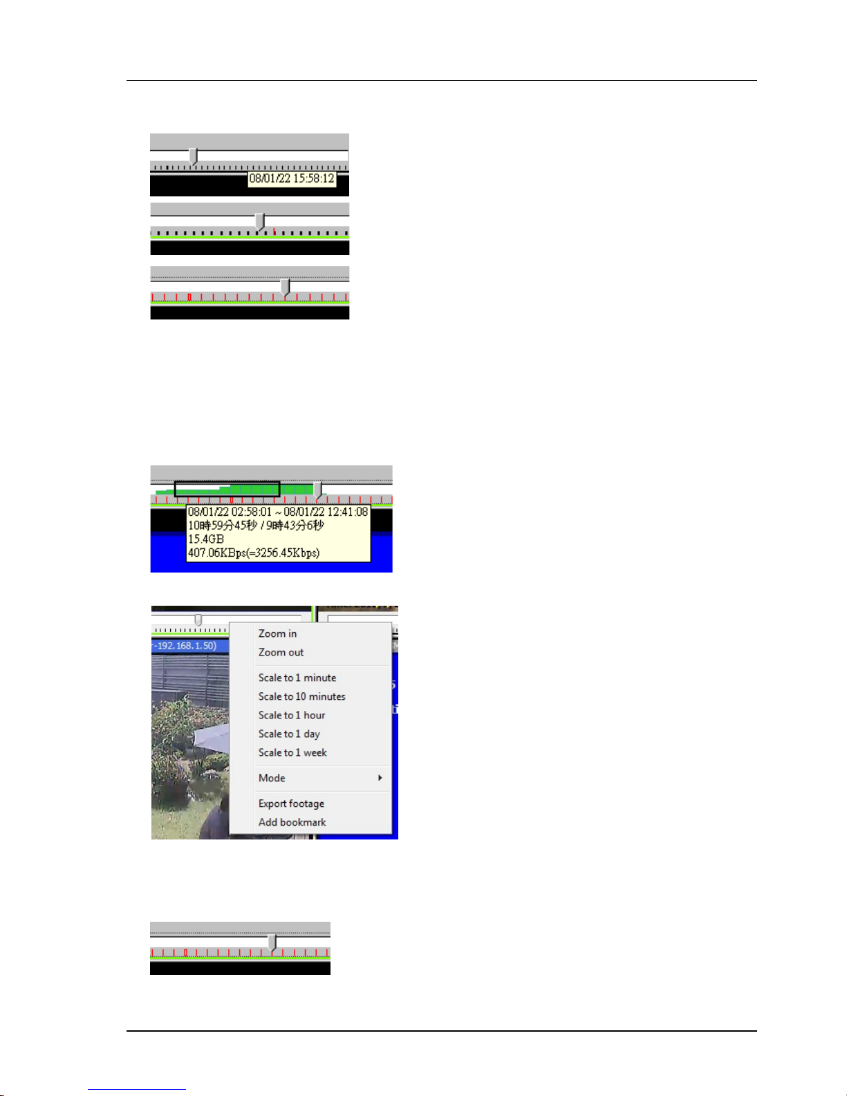
Chapter 5. NVR SYSTEM OPERATION
91
5.6.3 Basic operations
Drag on the ticks to navigate in the timeline (the cursor changes to four-way arrow before you can do this).
Use mouse wheel to zoom in/out. The ticks change automatically depends on the scale. You can also hover
on the timeline to see the exact time.
There're four types of ticks. The black thin lines are for seconds. Black thick ones are for minutes. Red thin
lines are for hours. Red boxes are for days.
You can also select an interval by mouse dragging in the track bar area. The interval length will be displayed.
Fast navigation are also available in context menu.
5.6.4 Playback
You can double click on anywhere in track bar area of the timeline to jump to that time point, or drag the
arrow.
Page 92
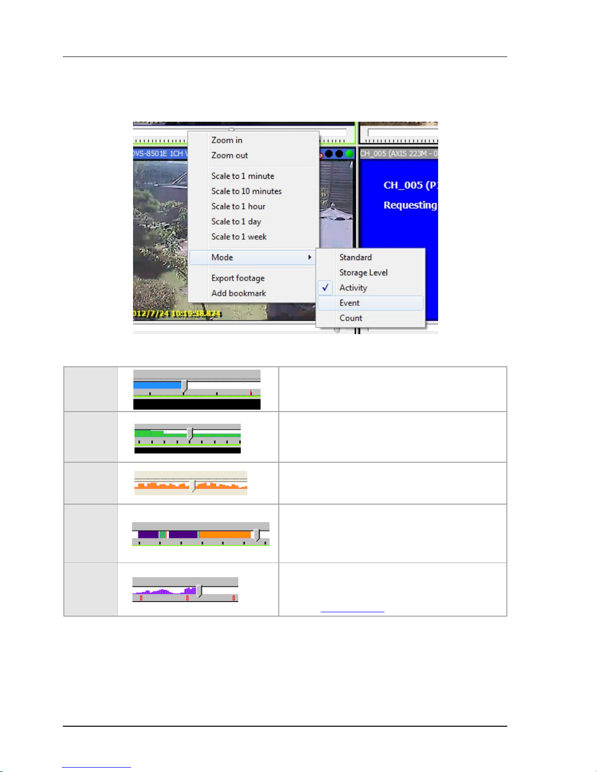
Chapter 5. NVR SYSTEM OPERATION
92
5.6.5 Timeline modes
Please Note: Not all editions of software license has this feature enabled. Check with feature matrix for
more details.
There are various modes in timeline to display different information. It can be set by right click on the
timeline.
Standard
Blue area indicates that there are recorded data.
White area means there's no recorded data.
Storage
level
Green blocks indicate the storage level of recorded
data. This is the average of a fixed time span, which
depends on the scale of the timeline. In this mode,
user can calculate storage by selecting an interval.
Activity
The height of the orange block is the counts of
activities in a fixed time span, which depends on the
scale of the timeline.
Event
Orange: activity
Green: recording
Purple: unexpected system off
Gray: normal system off
Counting
The purple bar shows the level of tripwire counting.
Results of all tripwires in this channel are summed
up, including both directions of every tripwire.
See also Object Tracking
Page 93
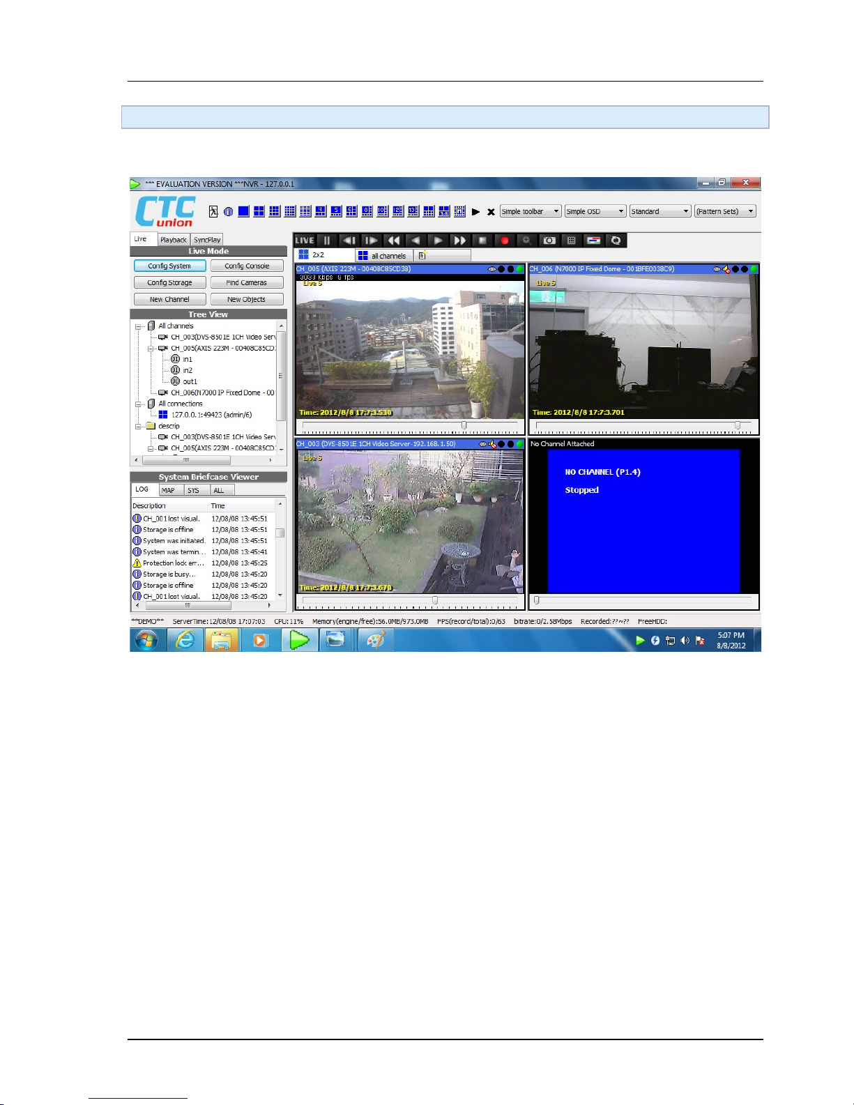
Chapter 5. NVR SYSTEM OPERATION
93
5.7 Synchronized playback
Enable synchronized playback
When synchronized playback is enabled, the play control of all players is synchronized. The video is
synchronized to the focused player when playback is requested.
The timestamp of all synchronized channels may not match exactly. Because it's impossible for every
channel to have available frame for any given time. This is obvious especially when the frame rate is low.
Page 94
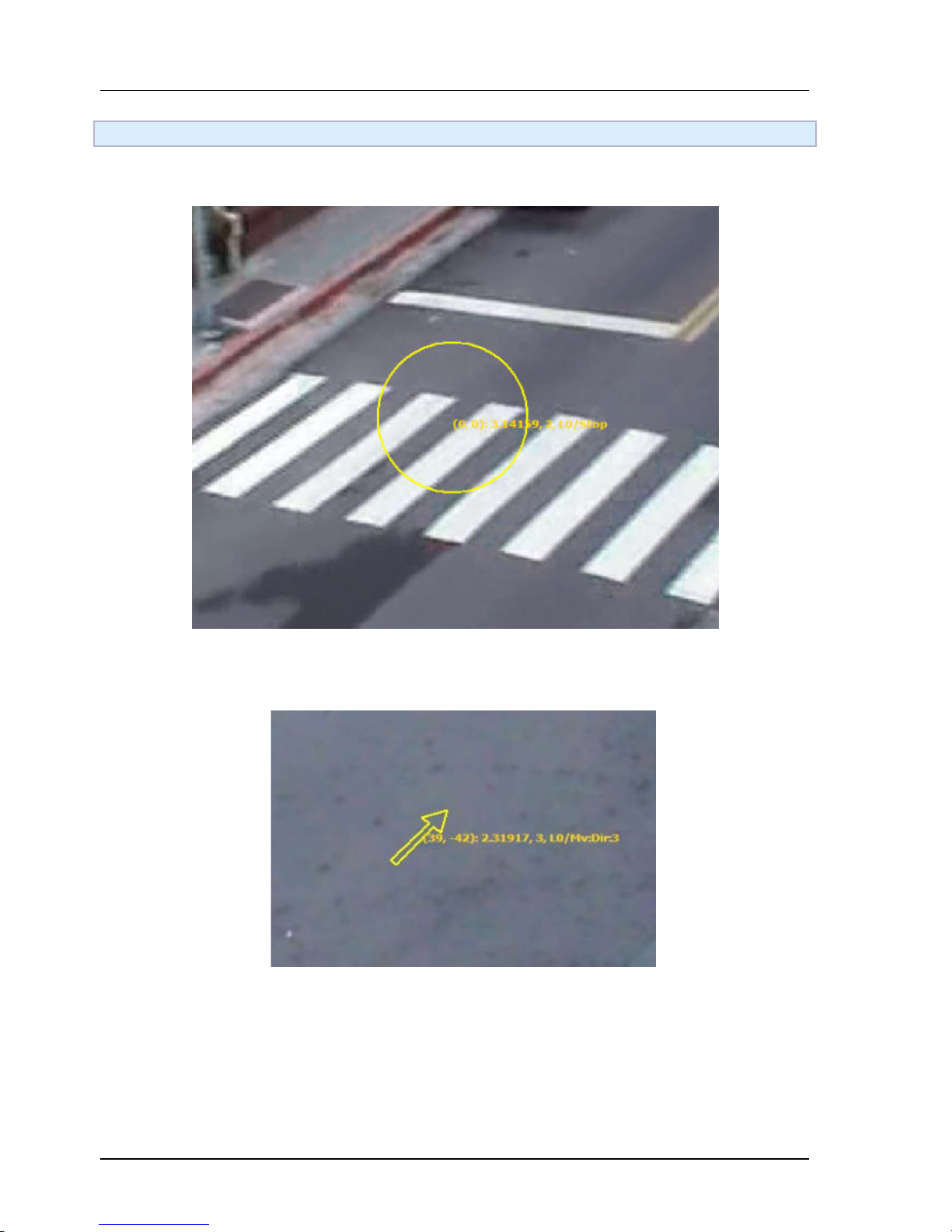
Chapter 5. NVR SYSTEM OPERATION
94
5.8 PTZ
5.8.1 Basic operation
If a channel support PTZ and is attached to a player, users can hold left mouse button on it to start PTZ
control. An yellow circle appears when the operation is valid. Hold mouse button and drag to the direction
you want the PTZ camera to turn.
A yellow arrow indicates the direction and the speed to turn the PTZ camera. The camera turns faster when
the arrow is longer. To stop the camera, simply release mouse button. To zoom in/out, use the mouse
wheel.
Page 95
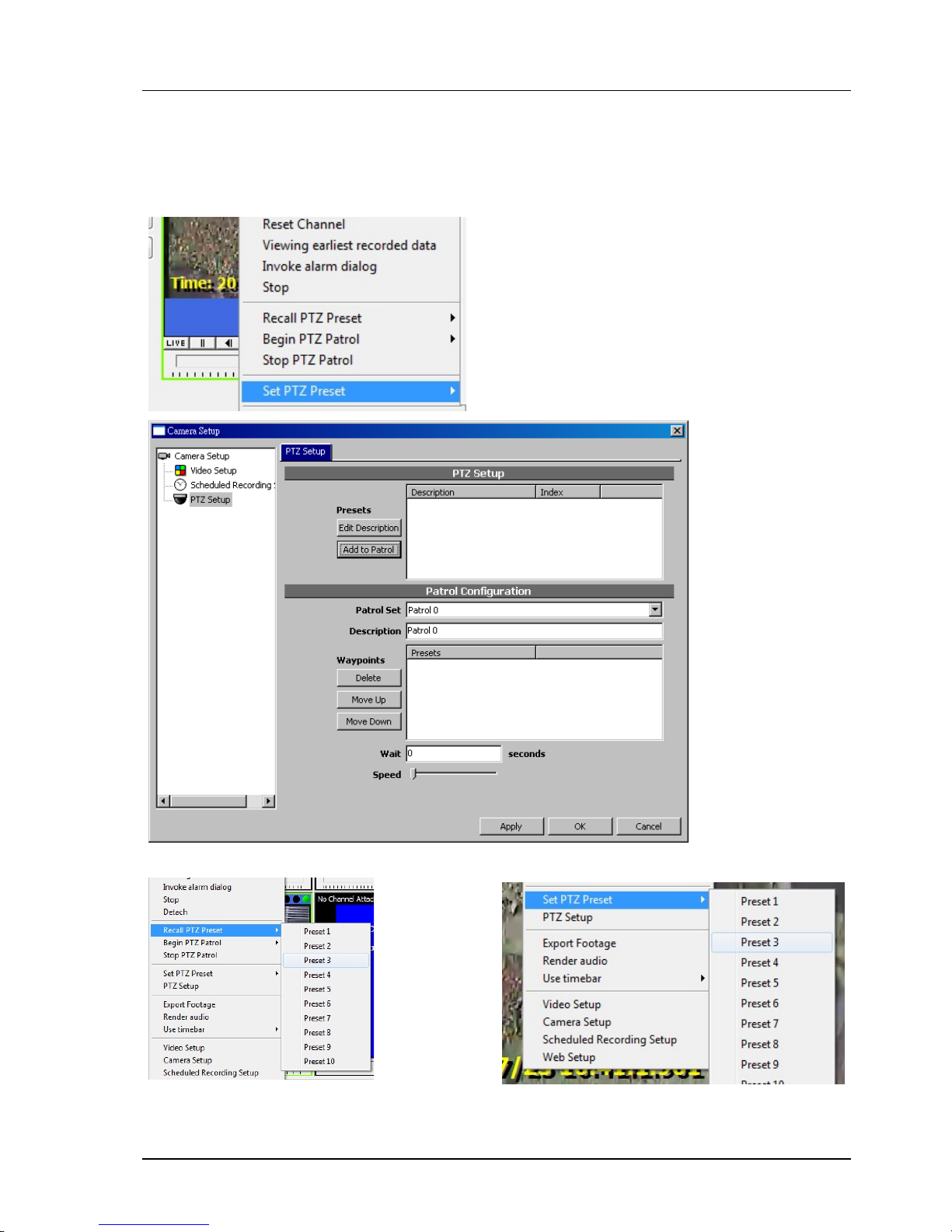
Chapter 5. NVR SYSTEM OPERATION
95
5.8.2 Presets
Before you can use presets, you must first configure PTZ configuration. To invoke the configuration dialog,
click PTZ config in player context menu. If there's no PTZ config item in the context menu, check the video
configuration to see if the proper PTZ type is selected. For more information, check Video Configuration.
The description can be renamed by clicking on its description. Click OK when you done with configuration.
After PTZ is configured, you can use context menu of player to set or recall presets. Or use keyboard 0-9
to recall when the player is focused.
Page 96
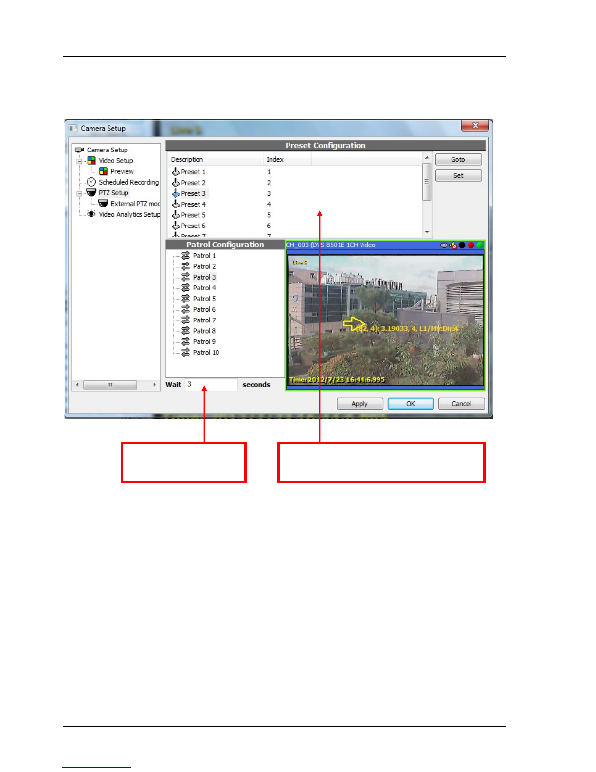
Chapter 5. NVR SYSTEM OPERATION
96
5.8.3 Patrol
Patrol is a list of presets to be called in sequence. You can manage up to 10 patrols in the PTZ
dialog.
<NOTE> PTZ functionality is limited by the actual specs and SDK support of the hardware. Not all models
support the functions mentioned above.
To add a preset in the patrol, drag it from
Preset List and drop it in Patrol.
The interval and speed of
patrol can be set.
Page 97
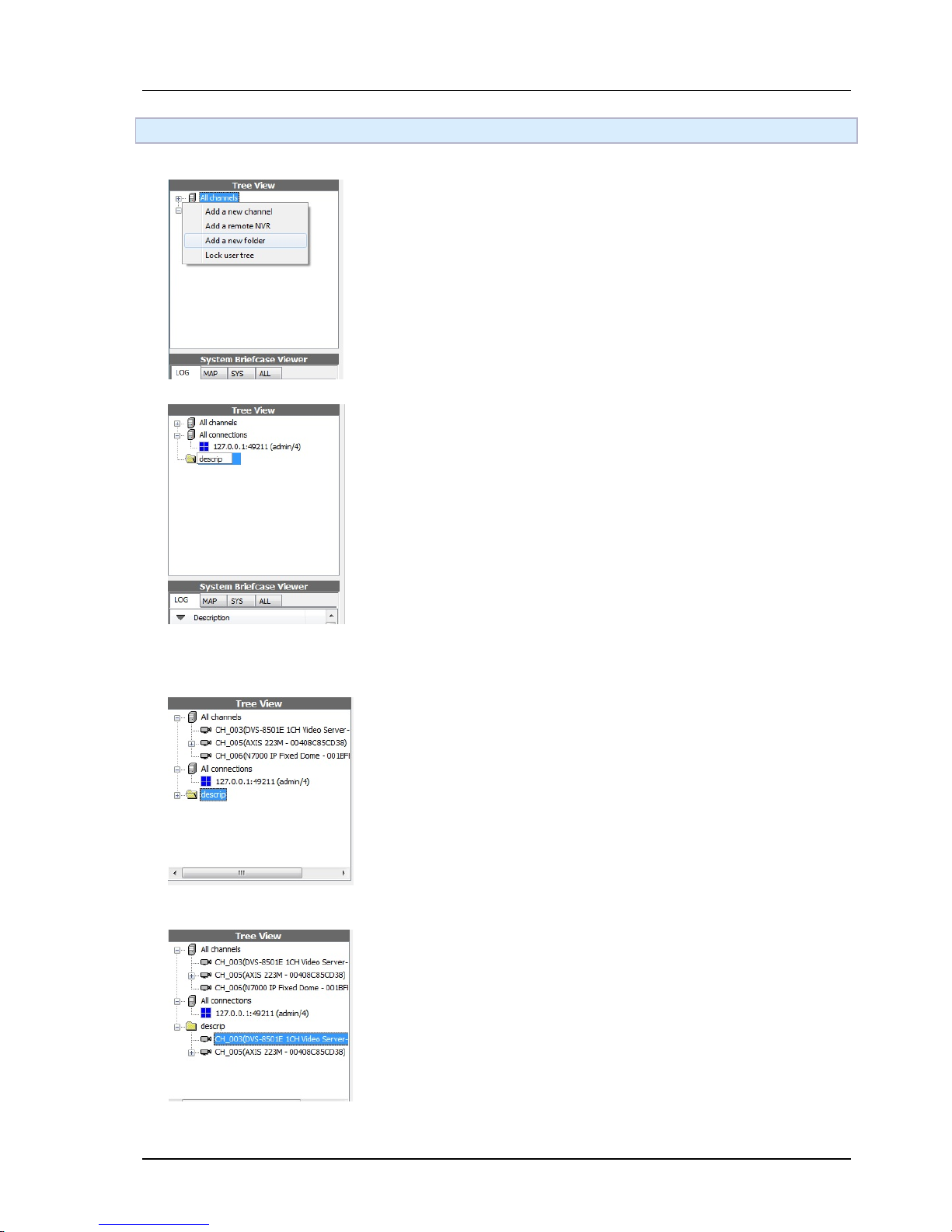
Chapter 5. NVR SYSTEM OPERATION
97
5.9 Building user tree
Add/edit folders
To add a new folder, right-click on blank area and click Add a new folder
To edit folder description, click it again when it's already selected.
Add/edit tree items
To create a channel representative in user-created folder, drag a channel from folder All channels to
the destined folder.
To change the order of items, drag and drop it in the tree.
Page 98
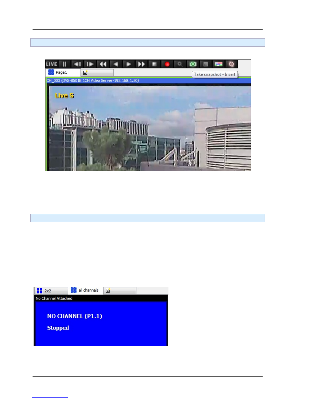
Chapter 5. NVR SYSTEM OPERATION
98
5.10 Taking snapshot
To take a snapshot, click the camera button in the player toolbar. A message will be poped if the snapshot
is taken.
5.11 Managing layout pages
Overview
A page is a set of players with its own layout settings and player states. Each page is configured separately
and will not affect other pages. Users can create multiple pages and configure them for management
purposes. For example, you can create a page named it "all channels". Switch its layout to 4x4 and attach
16 channels in it. And then create another page named "map". Switch it to 1x1 and open a map. Then you
can switch between the two pages easily without open multiple windows or applications.
Add a new page
Click on the right most tab button to add a new page.
Page 99
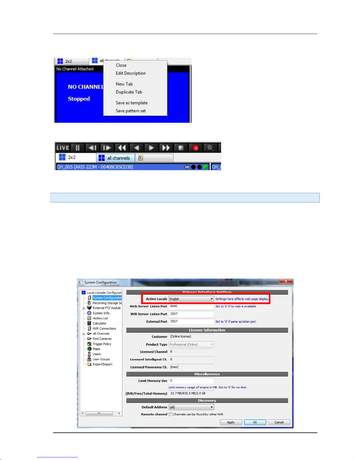
Chapter 5. NVR SYSTEM OPERATION
99
Editing pages
User can create, remove, and rename tabs in pattern tab control. Each pattern tab has its own
layout and state. You can also drag the tab to change the order of the pages.
5.12 Tour
Design tour phases
You can use tab managing functions to create pattern pages and properly order them as the actual tour
required.
Activating/stopping tour
Press F11 to toggle activating or stopping tour.
Configuring tour interval
Open the local console configuration dialog.
Page 100
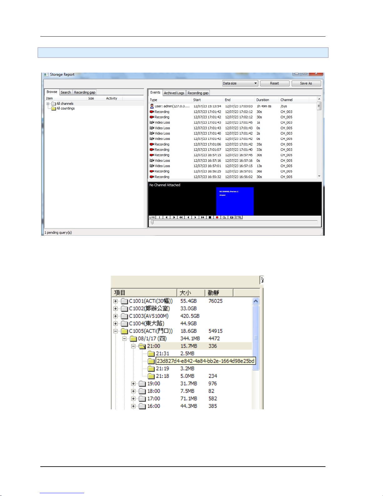
Chapter 5. NVR SYSTEM OPERATION
100
5.13 Storage Report
GUI overview
By using the sub nodes of the root nodes, you can easily explore recorded video in the scale of days, hours,
or minutes. The second column indicates the size accumulated of the item. The third is called the activity
indication value. If this value is larger than more activity has happened during that period.
Event viewing
At right panel you can view the related events to the selected period of time. If you wish to examine the
video of a specific event, you can either double-click the event to let an idle player to play it. Or that you
can drag it to a specific player to play it.
 Loading...