

Page 1

IPM-E1
E1 over IP Multiplexer
Page 2

Page 3

LEGAL
The information in this publication has been carefully checked and is believed to be entirely accurate at the time of
publication. CTC Union Technologies assumes no responsibility, however, for possible errors or omissions, or for any
consequences resulting from the use of the information contained herein. CTC Union Technologies reserves the right
to make changes in its products or product specifications with the intent to improve function or design at any time
and without notice and is not required to update this documentation to reflect such changes.
CTC Union Technologies makes no warranty, representation, or guarantee regarding the suitability of its products for
any particular purpose, nor does CTC Union assume any liability arising out of the application or use of any product
and specifically disclaims any and all liability, including without limitation any consequential or incidental damages.
CTC Union products are not designed, intended, or authorized for use in systems or applications intended to support
or sustain life, or for any other application in which the failure of the product could create a situation where personal
injury or death may occur. Should the Buyer purchase or use a CTC Union product for any such unintended or
unauthorized application, the Buyer shall indemnify and hold CTC Union Technologies and its officers, employees,
subsidiaries, affiliates, and distributors harmless against all claims, costs, damages, expenses, and reasonable attorney
fees arising out of, either directly or indirectly, any claim of personal injury or death that may be associated with such
unintended or unauthorized use, even if such claim alleges that CTC Union Technologies was negligent regarding the
design or manufacture of said product.
TRADEMARKS
Microsoft is a registered trademark of Microsoft Corp.
HyperTerminal™ is a registered trademark of Hilgraeve Inc.
WARNING:
This equipment has been tested and found to comply with the limits for a Class A digital device, pursuant to Part 15 of
the FCC Rules. These limits are designed to provide reasonable protection against harmful interference when the
equipment is operated in a commercial environment. This equipment generates, uses, and can radiate radio
frequency energy and if not installed and used in accordance with the instruction manual may cause harmful
interference in which case the user will be required to correct the interference at his own expense. NOTICE: (1) The
changes or modifications not expressively approved by the party responsible for compliance could void the user's
authority to operate the equipment. (2) Shielded interface cables and AC power cord, if any, must be used in order to
comply with the emission limits.
CISPR PUB.22 Class A COMPLIANCE:
This device complies with EMC directive of the European Community and meets or exceeds the following technical
standard. EN 55022 - Limits and Methods of Measurement of Radio Interference Characteristics of Information
Technology Equipment. This device complies with CISPR Class A.
WARNING:
This is a Class A product. In a domestic environment this product may cause radio interference in which case the user
may be required to take adequate measures.
CE NOTICE
Marking by the symbol CE indicates compliance of this equipment to the EMC directive of the European Community.
Such marking is indicative that this equipment meets or exceeds the following technical standards: EN
55022:1994/A1:1995/A2:1997 Class A and EN61000-3-2:1995, EN61000-3-3:1995 and EN50082-1:1997
Page 4

CTC Union Technologies Co., Ltd.
Far Eastern Vienna Technology Center (Neihu Technology Park)
8F, No. 60, Zhouzi St.
Neihu, Taipei, 114
Taiwan
Phone: +886-2-2659-1021
FAX: +886-2-2799-1355
IPM-E1
1, 2, 4, 8 or 16 E1 over IP Multiplexer.
User Manual
Version 2.1 July 3, 2014
This manual supports the following models:
IPM-1E1-AD
IPM-2E1-AD
IPM-4E1-AD
IPM-8E1-AD
IPM-16E1-AD
This document is the current official release manual. Please check CTC Union's website for any updated manual or
contact us by E-mail at [email protected]. Please address any comments for improving this manual or to point out
omissions or errors to [email protected]. Thank you.
2014 CTC Union Technologies Co., Ltd.
All Rights Reserved
The contents of this document are subject to change without any prior notice.
Page 5

Table of Contents
i
CHAPTER 1. INTRODUCTION .................................................................................................................................... 7
1.1 WELCOME .................................................................................................................................................................... 7
1.2 FUNCTIONAL DESCRIPTION ............................................................................................................................................... 7
1.3 FEATURES ..................................................................................................................................................................... 7
1.4 IPMUX OUTLOOK .......................................................................................................................................................... 7
1.5 APPLICATIONS OF IPMUX ................................................................................................................................................ 7
1.6 TECHNICAL SPECIFICATIONS .............................................................................................................................................. 8
1.7 ORDER INFORMATION ..................................................................................................................................................... 8
CHAPTER 2. INSTALLATION ...................................................................................................................................... 9
2.1 DESCRIPTION ................................................................................................................................................................. 9
2.2 UNPACKING .................................................................................................................................................................. 9
2.3 SITE REQUIREMENTS ....................................................................................................................................................... 9
2.4 SITE SELECTION .............................................................................................................................................................. 9
2.5 AC OR DC ELECTRICAL OUTLET CONNECTION ...................................................................................................................... 9
2.6 RACK INSTALLATION CONFIGURATION ................................................................................................................................ 9
2.7 GETTING STARTED ........................................................................................................................................................ 10
CHAPTER 3. CONFIGURATION AND OPERATION ..................................................................................................... 11
3.1 DESCRIPTION ............................................................................................................................................................... 11
3.2 FRONT PANEL .............................................................................................................................................................. 11
3.3 REAR PANEL ................................................................................................................................................................ 13
3.4 LOOPBACK MODES ....................................................................................................................................................... 14
3.5 IP CONFIGURATION ...................................................................................................................................................... 14
3.6 INTERFACE CONFIGURATION ........................................................................................................................................... 14
3.7 FAULT REPORT ............................................................................................................................................................. 14
3.8 SAVE CONFIGURATION .................................................................................................................................................. 14
3.9 COMMAND LINE INTERFACE FOR SETUP ............................................................................................................................ 15
3.10 WEB BASED MANAGEMENT ......................................................................................................................................... 18
3.10.1 IP Address Configuration ................................................................................................................................ 19
3.10.2 Port General Configuration ............................................................................................................................ 19
3.10.3 TDM Configuration ......................................................................................................................................... 20
3.10.4 Alarm History Display ..................................................................................................................................... 21
3.10.5 Time Configuration ......................................................................................................................................... 21
3.10.6 Backup & Restore Configuration .................................................................................................................... 22
3.10.7 Save and Reboot Configuration ...................................................................................................................... 22
3.10.8 Firmware Upgrade ......................................................................................................................................... 23
APPENDIX ............................................................................................................................................................. 24
Page 6

Page 7
Chapter 1 Introduction
7
Chapter 1. Introduction
1.1 Welcome
Thank you for choosing CTC Union's IP multiplexer product as your migrating solution to an all IP based network.
This user manual will help to explain the settings of this equipment. Due to popular demand, this new generation of
multiplexers provides the ability to provision via simple point and click Web interface. The more complex CLI
(command line interface) is still available for experienced engineers and is the only method available for Telnet.
1.2 Functional Description
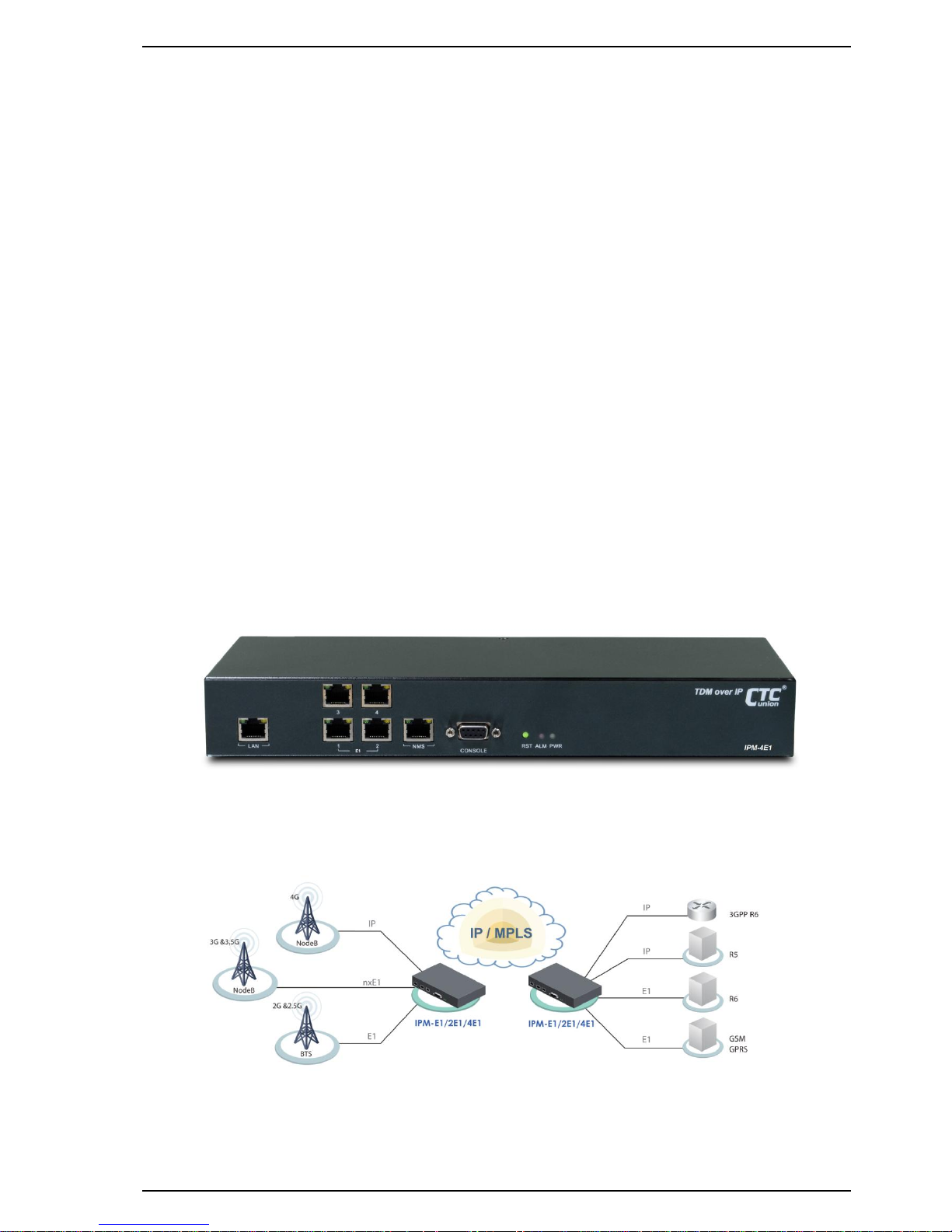
The IPMux series is a "Multi-service (TDM and Ethernet) over Ethernet" bridge, which transports up to sixteen ports
of E1 and one LAN into Ethernet packets. The target application, shown in Figure 1.4.1, is transparent E1 port
interconnection via IP network (using Ethernet packets). IPMux series implements the newest Circuit Emulation
System over IP technology as defined by IETF (Internet Engineering Task Force).
The E1 over IP of IPMux is compliant with IETF "CES over IP" standard. Versatile LEDs are provided for alarms and
status indication.
1.3 Features
Supports 1~16 E1 (1,2,4,8,16) over 100M Ethernet (WAN).
Provides 1-port Ethernet LAN for Ethernet access (1,2,4E1 units only).
User side has standard TDM (E1) interfaces.
Full-duplex 100Mbps Ethernet Interface.
Provides auto-negotiation which can auto configure IPMux to 100M depending on the speed of Ethernet port.
Supports "E1" clock source with alternative "E1 line recovered clock", "adaptive clock" or "internal clock".
Provides "ACT" and "ALM" LED indicators for each TDM interface.
Provides "Link/Activity" and "Link Speed" LED indicators for Ethernet interface.
Standalone desktop unit, optional 19" rackmount.
Power Supports built-in "AC 110/220 VAC input" and "DC -36 ~ -60VDC input"
1.4 IPMux Outlook
Figure 1.4.1 IPMux 4-Port E1 Outlook
1.5 Applications of IPMux
The IPMux is mainly applied for the solution of wire line usage connected with PSTN via E1 and Router via
100BaseTx and for integrating the various equipment based on traditional TDM and popular IP services.
Figure 1.5.1 Application Configuration of IPMux Multiplexer
Page 8

Chapter 1 Introduction
8
1.6 Technical Specifications
(1) Construction
Physical Dimension
Height: 44 mm (1U)
Width: 320 mm (1, 2 & 4E1), 290 mm (8 & 16E1)
Depth: 125 mm (1, 2 & 4E1), 267 mm (8 & 16E1)
Weight: 1.4 Kg (1, 2 & 4E1), 2.4kg (8 & 16E1)
(2) 100M Ethernet Interface
a. Compliant with 802.3/802.3u standards
b. 100-BaseT with RJ45 connector
c. Full-duplex
d. Support Auto-negotiation
e. LED indicator for Ethernet: Link status and Act activity
(3) TDM Interfaces : E1 Interface
a. Data Rate: 2.048 Mbit/s 50 ppm
b. Line Code: Bipolar with HDB3
c. Test Load Impedance: 120 ohms± 5% resistive, balanced.
d. LED indications for E1: ACT, ALM
e. Connector Type: USOC RJ48C
(4) Power Supply
a. AC: 85~264V, 47~63Hz and DC: -36 ~ -60 V
b. Maximum Power Consumption: < 15 watts
(5) Operating Environment
a. Ambient temperature: 0 ~ 40° C for indoor application
b. Storage temperature: 0 ~ 85° C
c. Relative humidity: 5 ~ 95% non condensing
1.7 Order Information
Feature Options:
[ Downlink Interface ] □ 1x E1 □ 2x E1 □ 4x E1 □ 8x E1 □ 16x E1
[ Management ] □RS232 terminal □ RS232 terminal + SNMP-based MIB management
[ Power ] □ 1x AC + 1x DC
Page 9
Chapter 2 Installation
9
Chapter 2. Installation
2.1 Description
This chapter provides the information needed to install IPMux series. It is important to follow the installation
instructions to ensure normal operation of the system and to prevent damages from human negligence.
2.2 Unpacking
If there is a possibility for future relocation of the IPMux unit, please keep the packing cartons and protective
packaging material.
Please carefully unpack and inspect the unit and accessories for potentially damaged or missing parts. Contact our
nearest sales representative or our company directly if you detect any damaged or missing parts. Improper handling
during shipment may cause early failure.
2.3 Site Requirements
Users should follow the precautions below to insure the safety and to minimize the risk of damage to the
equipment:
Make sure that the power outlet is properly grounded. Please refer to article 250 of the National Electrical Code
(NEC) Handbook. Proper grounding should include a minimum of:
A grounded rod buried outside the building at least 8 feet (2.44 meters) deep.
2.4 Site Selection
For best performance, the distance of 6 feet (1.83 meters) from the AC power outlet to IPMux series is preferred. To
allow easy access to the equipment, leave at least 36 inches (90 cm) clearance in the front and at least 4 inches (10.2
cm) at the rear.
Caution: To avoid overheating, leave at least 1 inch (2.5 cm) on either side of the IPMux series. Also, DO NOT
stack other equipments on top of the IPMux unit in order to ventilate the system normally.
2.5 AC or DC Electrical Outlet Connection
For safety and to prevent damage to IPMux series, make sure that the power requirement matches the appearance
of user electric outlets. Connect power source to IPMux unit and power on the equipment.
Caution: Damage to compact key components may occur if the output voltage applied to device is not within
the specified range.
2.6 Rack Installation Configuration
There are 3 common parts for each IPMux package, including one set of TDM over IP multiplexer, one AC power
cable. If IPMux is intended to be mounted into a rack, a pair of L-shaped brackets with 10 screws are also included in
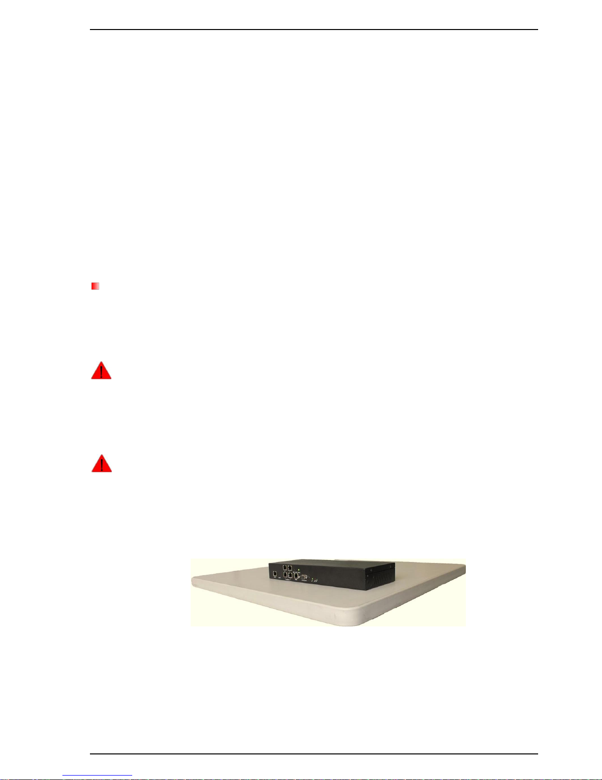
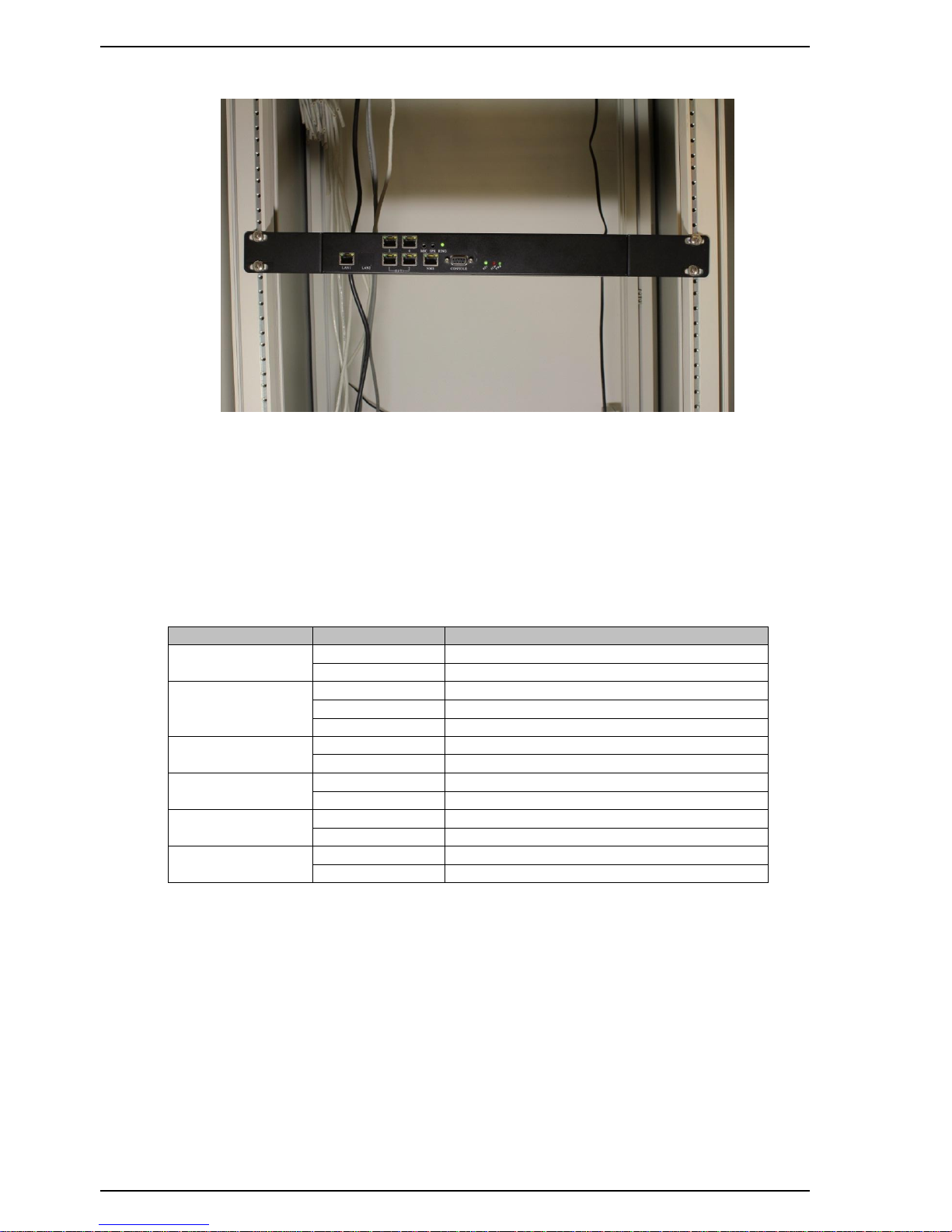
the package. The following Figure 2.6.1 shows the unit on a desktop. Figure 2.6.2 shows the unit in a rack.
Figure 2.6.1 IPMux series on a desktop
Page 10
Chapter 2 Installation
10
Figure 2.6.2 IPMux series mounted in a rack
2.7 Getting Started
1. Place both CO and CPE IPMux devices on a flat work surface.
2. Connect the Ethernet cable to the CO IPMux device's WAN port and the other end of the Ethernet cable to the CPE
IPMux device's WAN port.
3. Ensure that CO and CPE IPMux devices are both switched on.
4. Connect your computer to the LAN port of the IPMux device.
5. Check LAN and WAN Ethernet ports LED status as shown in Table2.7.1.
6. You may need to set up further parameters via a RS232 console port or a telnet session as described in section 3.9
"Command Line Interface for Setup". Examples to configure IPMux can be found in Appendix section.
LED Name
State
Description
PWR
Green
Power is on.
Off
No power present.
Ethernet Link/Activity
Green
Ethernet link is up.
Blinking Green
Tx/Rx traffic is traversing the port.
Off
Ethernet Link is down.
Ethernet Link Speed
Yellow
100 Mbps
Off
10 Mbps
E1 ACT
Green
E1 port is enabled and traffic is traversing the port.
Off
E1 port is disabled.
E1 ALM
Yellow
E1 link error has occurred.
Off
No alarm present.
ALM
Red
Alarms raised from any of E1 link
Off
No alarm present.
Table 2.7.1 LED Indications of IPMux 1/2/4/8/16-Port E1
Page 11
Chapter 3 Configuration and Operation
11
Chapter 3. Configuration and Operation
3.1 Description
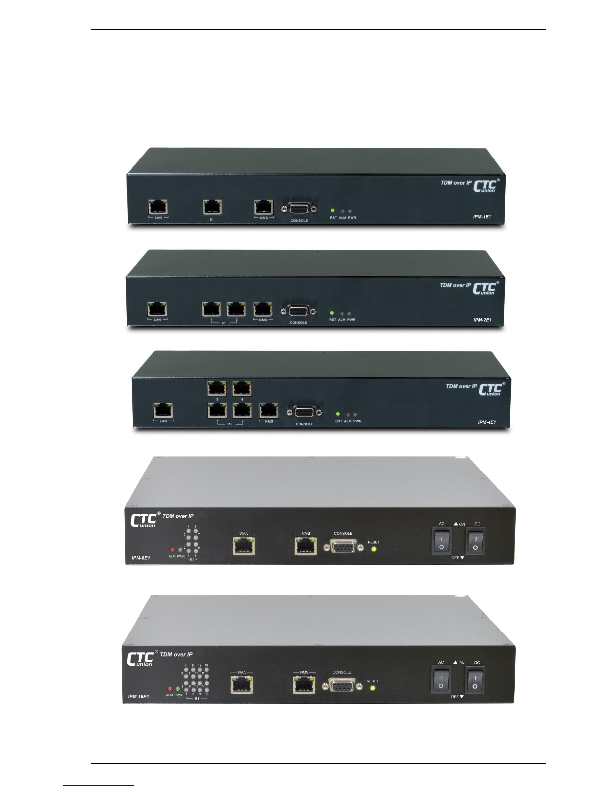
IPMux series consists of the front panel and the rear panel. The views and description of front and rear panels are
shown in Figure 3.2.1 and 3.3.1 for details.
3.2 Front Panel
Figure 3.2.1 IPMux 1-Port E1 Front Panel
Figure 3.2.2 IPMux 2-Port E1 Front Panel
Figure 3.2.3 IPMux 4-Port E1 Front Panel
Figure 3.2.4 IPMux 8-Port E1 Front Panel
Figure 3.2.5 IPMux 16-Port E1 Front Panel
Page 12
Chapter 3 Configuration and Operation
12
(1) System Indicators
PWR (Power On/Off LED)
ALM (failures/errors from any of E1 link)
(2) RST Button
Use this button to restart the system.
(3) LAN Ethernet Connector and Indicators
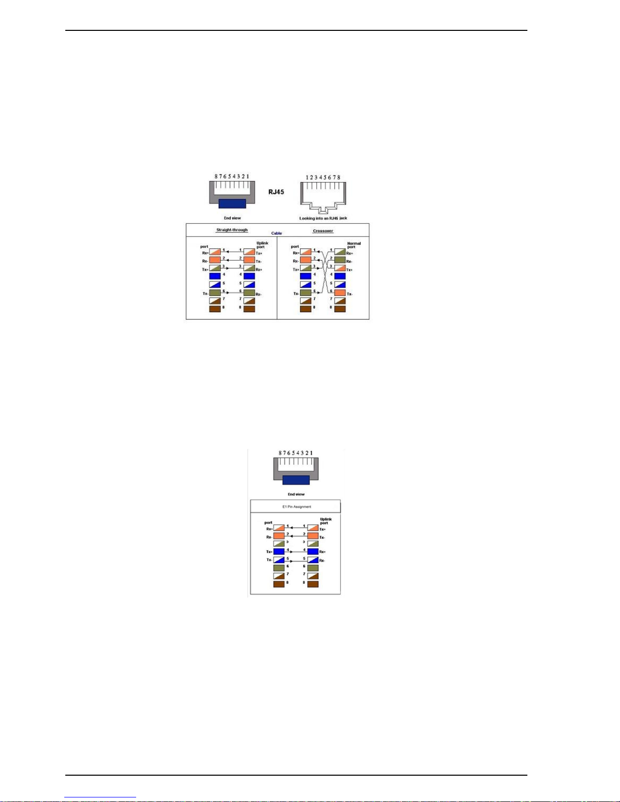
The Ethernet interface is a RJ45 connector with two LED indicators and its pin assignments are shown in Figure 3.2.6.
Two LED indicators are described below.
Green LED: Solid Green indicates Ethernet link is up; Blinking Green indicates Tx/Rx traffic is traversing the port.
Yellow LED: Solid Yellow indicates 100 Mbps link speed; Off indicates 10 Mbps link speed.
Figure 3.2.6 Ethernet Pin Assignment
(4) E1 Interface Connectors and Indicators
The E1 interface is a RJ48c connector with two LED indicators.
Green LED: Solid Green indicates E1 port is enabled and traffic is traversing the port; Off indicates E1 port is
disabled.
Yellow LED: Solid Yellow Indicates E1 link error has occurred; Off indicates no alarms or failures.
The "Yellow" LED indicates one of the following alarms occurred:
E1 LOS, LOF, AIS or L-bit received from the remote device.
E1 Pin Assignments are shown in Figure 3.2.7.
Figure 3.2.7 E1 Pin Assignments
(5) RS232 Connector
A RS232 interface with baud-rate 115200bps via DB9 (female)-to-DB9 (male) cable is provided for diagnostic. The
user commands (CLI command) are listed in Table 3.9.1.
(6) NMS Ethernet port
This Ethernet port is used for device management (local or remote access via Telnet or SNMP-based management).
Embedded web server provides a user-friendly interface for the management of IPMux devices.
Page 13
Chapter 3 Configuration and Operation
13
3.3 Rear Panel
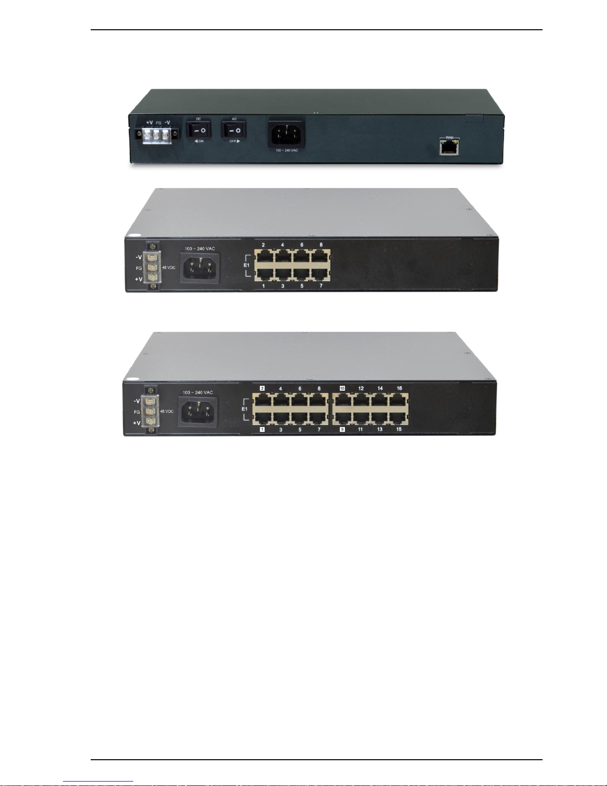
Figure 3.3.1 IPMux 1, 2, 4E1 Rear Panel
Figure 3.3.2 IPMux 8E1 Rear Panel
Figure 3.3.3 IPMux 16E1 Rear Panel
(1) WAN Ethernet Interface:
The Ethernet interface is a RJ45 connector with two LEDs and its pin assignments are shown in Figure 3.2.6. Two LED
indicators are described below.
GREEN LED: Solid Green indicates Ethernet link is Up; Blinking Green indicates Tx/Rx traffic is traversing the port.
YELLOW LED: Solid Yellow indicates 100 Mbps link speed; Off indicates 10 Mbps link speed.
(2) AC Power Socket and Switch (On/Off switch for AC):
The built-in power module provides AC 110V/220V with the input voltage range of 85 to 264VAC.
(3) DC Power Socket and Switch (On/Off switch for DC):
The built-in -48VDC power module provides the power with the input voltage range of -36 to -60VDC.
Both built-in AC power module and built-in DC power module are shipped with IPMux.
Page 14

Chapter 3 Configuration and Operation
14
3.4 Loopback Modes
The IPMux provides two modes of loopback: "E1 Local Loopback" and "E1 Remote Loopback". (Please refer to Figure
3.4.1).
Figure 3.4.1 IPMux E1 Loopback Modes
3.5 IP Configuration
The IP address, subnet mask, and default gateway address can be setup through RS232 or Telnet.
3.6 Interface Configuration
LAN Ethernet port provides the bandwidth control. This feature allows users to limit the data rate from LAN to WAN
port. Implement this feature to ensure the quality of service in TDM circuits. For different applications, there are 16
different bandwidth options available for users to choose (50K, 100K, 150K, 200K, 250K, 300K, 350K, 400K, 800K, 1.6M,
3.2M, 6.4M, 12.8M, 25.6M, 51.2M and 100M). In addition, setting a 100Mbps bandwidth option is to only utilize the
rest of the available bandwidth of 100Mbps minus the bandwidth being reserved for all E1 traffic.
As for E1 interfaces, the LEDs will be lit after enabling the E1 channel. User can map to the different remote E1
channel for flexible selection (cross connection). Jitter Buffer is also used to minimize packet delay variations between
two devices, including 8 available options of 11, 23, 40, 75, 99, 145, 192 and 239 ms based on the standard Ethernet
frame size of 1518 bytes.
3.7 Fault Report
E1 active alarms can be displayed by executing a CLI command "almall". This information is useful for a technical
support personnel who performs diagnostic tasks. The alarms are interpreted as follows:
E1LOS: Loss of receiving signal of E1 from the upstream equipment connected to the E1 port.
E1AIS: AIS (Alarm Indication Signal, a message consisting of all "1"s) signal received from the upstream equipment
connected to the E1 port.
PWLBIT: E1 LOS or AIS alarm has been raised at the remote E1 port.
PWRBIT: Packets loss occurred at remote Ethernet WAN port.
PWSEQNUMERR: Packets received out of sequence at local Ethernet WAN port.
JBUFEMP: Jitter buffer empty occurred at the E1 port. (Possible reasons could be due to WAN port Ethernet link
down or pseudo-wire ID mismatched.)
JBUFOV: Jitter buffer overflow occurred at the E1 port.
3.8 Save Configuration
After change the settings of device, please execute csave command to save the new settings to the device. This can
prevent all of your settings being lost if you reboot or power cycle the device.
Page 15

Chapter 3 Configuration and Operation
15
3.9 Command Line Interface for Setup
a. Serial Terminal Emulation
When logging into the terminal, set up the RS-232 port as follows:
Bit rate: 115200bps
Data bit: 8
Parity: none
Stop bit: 1
Flow control: none
Login password: admin
b. Telnet as Remote Terminal
The IPMux device supports a telnet service for remote configuration. Any host with telnet client enabled can access
to the CLI (command line interface) of the IPMux device. The telnet port has been changed to port 8888 because of
security issues with default port 23. Please follow instructions below to remotely log into a device via telnet
connection. The illustration is based on IPMux device default factory settings listed below.
IPMux CO/CPE Device Settings
CO device (Factory defaults)
CPE device
NMS port IP address
192.168.1.11
192.168.2.11
NMS port subnet mask
255.255.255.0
255.255.255.0
Default gateway
172.16.1.2
172.16.1.1
WAN port IP address
172.16.1.1
172.16.1.2
WAN port subnet mask
255.255.255.0
255.255.255.0
LAN to WAN port bandwidth
400Kbps
400Kbps
To telnet to an IPMux CO device from your computer, connect your computer to the LAN port of CO device with an
Ethernet cable, and follow these steps:
Step 1: Configure your computer IP address as 172.16.1.100 and subnet mask set to 255.255.255.0
Step 2: On the command terminal of your computer, type telnet 172.16.1.1 8888.
Step 3: When the device prompts a password, just enter the default password "admin".
Step 4: Type ? to display a list of commands available for a user.
Step 5: If want to see a full list of commands, type "passwd" command and input password "gciadmin" to enter
administration mode.
Step 6: Type ? to display a full list of commands.
To telnet to an IPMux CPE device from your computer, connect your computer to the LAN port of CPE device with
an Ethernet cable, then follow same steps described above except Step 2 type telnet 172.16.1.2 8888 instead, telnet
to a CPE device’s IP address.
The CLI commands are summarized as the following table:
Table 3.9.1 CLI Command Description
CLI Command
Description
System Command
logout
Logout CLI System
cdisp
Display IPMux current configurations.
csave
Save current configurations: IPMux & relative setting.
cload
Load configuration setting from FLASH.
passwd
Enter password to change user-mode. (i.e. View/Setup/Admin mode)
PS: If inputted password is not for "setup" or "admin", it will enter the "view" mode.
setpass mode
Modify password for user-mode.
mode: ‘s’ for setup mode, ‘a’ for admin mode, ‘c’ for CLI login
ipset ip_addr net_mask
gw_addr
Set NMS port IP address, subnet mask and gateway address.
ip_addr: NMS port IP address to be assigned.
net_mask: subnet mask of IP address.
gw_addr: gateway IP address.
Example: ipset 192.168.1.11 255.255.255.0 192.168.1.254
ipget
Display NMS port current IP address.
trapset mode trap_ip_addr
Set SNMP Trap Mode & Host IP
mode: 0 for disable SNMP trap, 1 for enable SNMP trap
Example: trapset 1 192.168.1.200
Page 16

Chapter 3 Configuration and Operation
16
CLI Command
Description
(enable SNMP trap function and set host 192.168.1.200 to receive the trap message)
trapget
Get SNMP Trap Mode & Host IP
ntpset mode server_ip_addr
Set NTP Enable Mode & NTP Server IP
mode: 0 for disable NTP function, 1 for enable NTP function
Example: ntpset 1 192.168.1.201
(enable NTP function and set NTP server address to192.168.1.201)
ntpget
Get NTP Enable Mode & NTP Server IP
upgrade tftp_server_ip
file_name
Upgrade SW image file from TFTP server
tftp_server_ip: TFTP server IP address
file_name: the file name of software image to be upgraded
EX: upgrade 172.16.1.101 IPMux_v100_f110418.bin
backup tftp_server_ip
file_name
Backup the system configuration to TFTP server
tftp_server_ip: TFTP server IP address
file_name: backup file name
EX: backup 172.16.1.101 IPMux_co_backup_1
restore tftp_server_ip
file_name
Restore the backup system configuration from TFTP server
tftp_server_ip: TFTP server IP address
file_name: backup file name
EX: restore 172.16.1.101 IPMux_co_backup_1
timeset hour min sec
Set current time with ‘hour’, ‘minute’ and ‘second’.
Example: timeset 7 30 00
(set IPMux’s real time clock to 7:30AM)
dateset year month day
Set current date with ‘year’, ‘mouth’ and ‘day’
Example: dateset 2011 07 05
(set IPMux’s date to July 5, 2011)
timeget
Get current time and date
ping ip_addr
Use ICMP to check connection
EX: ping 192.168.1.11
version
Display software version and related information
logout
Quit CLI session and return to CLI login prompt
reboot
Perform a warm startup on IPMux. Ethernet data will be interrupted during this
operation.
Provision Command
gci
Global Chipset Initialization of Middle Ware & CESoPSN chip
Initial relative Tasks, Messages and Semaphores.
srcnet ip_addr net_mask
[source_mac(AA:BB:CC)]
Set WAN port IP address, subnet mask, gateway IP address and its MAC address.
If source_mac is omitted, the last three numbers of WAN port IP address will be
used as its MAC address.
ip_addr: WAN port IP address to be assigned.
net_mask: subnet mask of IP address.
[source_mac(00:02:AB)](OUI is fixed): WAN port MAC address.
EX: srcnet 172.16.1.1 255.255.255.0
(WAN port MAC address will be set to OUI+10:01:01)
EX: srcnet 172.16.1.1 255.255.255.0 0A:0B:0C
(WAN port MAC address will be set to OUI+0A:0B:0C)
lanset enable bandwidth
Enable LAN port and set its bandwidth
enable: 0:disable, 1:enable LAN port
bandwidth: 0: 50Kbps, 1: 100Kbps, 2: 150Kbps, 3: 200Kbps,
4: 250Kbps, 5: 300Kbps, 6: 350Kbps, 7: 400Kbps,
8: 800Kbps, 9: 1.6Mbps, 10: 3.125Mbps, 11: 6.25Mbps,
12: 12.5Mbps, 13: 25Mbps, 14: 50Mbps, 15: 100Mbps.
EX: lanset 1 7 (enable LAN port and limit its bandwidth to 400Kbps)
vlanset op_mode
Enable or disable E1 channel vlan mode
op_mode: 0:disable, 1:enable
EX: vlanset 1 (enable E1 channel vlan mode)
ceschset ch_no enable
[dest_ip] [dest_mac]
Set CESoPSN Channel and its destination IP and MAC address of the remote device.
ch_no: E1 channel number (1~4)
enable: 0:disable, 1: enable.
[dest_ip]: destination IP address. Can be omitted if disable E1 channel.
[dest_mac]: destination MAC address.
Example 1: Enable E1 port #1, set the dest_ip, then automatically get the dest_mac
Page 17

Chapter 3 Configuration and Operation
17
CLI Command
Description
address from the remote device only if the local device can communicate with the
remote device via its WAN port.
EX: ceschset 1 1 172.16.1.2
Example 2: Enable E1 port #1 and specifically set the destination ip and mac address
of the remote device.
EX: ceschset 1 1 172.16.1.2 00:02:AB:DD:EE:FF
cespwidset ch_no TrPWID
PrPWID
Set CESoPSN Channel TrPWID and PrPWID.
ch_no: E1 channel number (1~4)
TrPWID: Transmit PW ID.
PrPWID: Provision PW ID.
EX: cespwidset 1 1 1
jitterbd ch_no depth
Set CESoPSN Channel Jitter Buffer Depth.
ch_no: E1 channel number (1~4)
depth(pktsize=0): jitter buffer depth 0~7 (0:11ms, 1:23ms, 2:40ms, 3:75ms,
4:99ms, 5:145ms, 6:192ms, 7:239ms )
EX: jitterbd 1 1 (set jitter buffer to 23msec when pkt_size is set to 1518 Bytes)
pktsize ch_no pkt_size
Set CESoPSN Channel Packet Size
ch_no: E1 channel number (1~4)
Pkt_size: 0 ~ 3 ( 0: 1514 Byte, 1: 782 Byte, 2: 178 Byte, 3: 306 Byte)
EX: pktsize 1 1
ceschclkset ch_no clksrc
Set Channel transmit clock source
ch_no: E1 channel number (1~4)
clksrc: 0:Adaptive, 1:Internal, 2:RxLine.
lpkset ch_no mode enable
Enable/Disable E1 channel loopback mode.
ch_no: E1 channel number (1~4)
mode: 0:Disable-All, 1:E1-Remote (FE), 2:E1-Local (NE)
enable: 0:disable, 1:enable.
EX: lpkset 1 1 1
lpkget
Get current loopback mode of E1 channel.
cesfe1mode ch_no en(1/0)
Set TDM PW to Transparent E1 (SAToP) or Fractional E1 N x 64k mode (CESoPSN)
ch_no: E1 channel number (1~4)
enable: 0:disable, 1: enable.
EX: ceschmode 1 1 (Set E1 port #1 to Fractional E1 (CESoPSN) mode)
cesfe1crc ch_no en(1/0)
E1 G.704 CRC4 generation/analyze control for Fractional E1 mode. This setting only
affect E1 ports set to FE1 N x 64k mode, for E1 ports set to Transparent E1 mode this
setting has no effect.
ch_no: E1 channel number (1~4)
enable: 0:disable, 1: enable.
EX: cesfe1crc 1 1 (Enable G.704 CRC4 generation/analyze on E1 port #1.)
cesfe1tsmap ch_no TsMap
Set 64k PCM channel number to be transported over the TDM PW for FE1 (CESoPSN)
mode. This setting only affect E1 ports set to FE1 N x 64k mode, for E1 ports set to
Transparent E1 mode this setting has no effect.
ch_no: E1 channel number (1~4)
TsMap: bit mask for DS0, b31:TS31 ~ b0:TS0
EX: cesfe1tsmap 1 x000007FE
Timeslot #1 ~ 10 of E1 port #1 will be transported over the TDM PW.
x000007FE (hexadecimal)=0000 0000 0000 0000 0000 0111 1111 1110 (binary)
TS31: the most left bit, TS0: the most right bit, TS0 is used for frame alignment and
can’t be counted in your timeslots and always set to 0.
ceschvlanvlpid ch_no vlp id
Set CESoPSN Channel vlan tag
ch_no: E1 channel number (1~4)
vlp: vlan priority, 0 ~ 7(highest priority)
id: vlan id, 0 ~ 0xFFF
Ex: ceschvlanvlpid 1 7 5 (set E1 port #1 traffic with vlan tag, set priority to 7 and set
vlan ID to 5)
Alarm Command
almall
Display all alarm status (CESoPSN)
Page 18
Chapter 3 Configuration and Operation
18
3.10 Web Based Management
Web management is a convenient configuration method that does not require memorizing complex commands. It
allows for quick configuration of TDM parameters by placing them all on one configuration page.
The web management of IPMux connects via non-standard port 6868 in an effort to detour hackers from accessing
the IPMux.
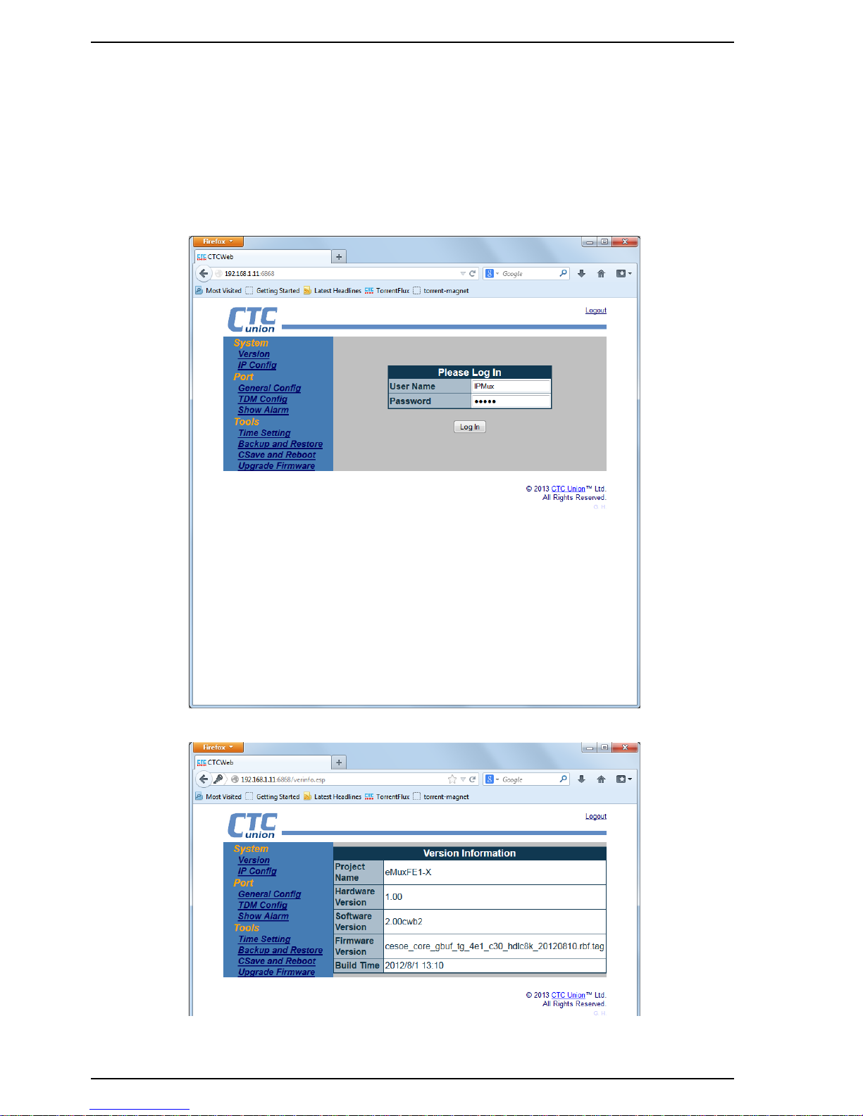
After checking the management IP address via console, or resetting the address, log into the IPMux using the
correct IP and the default 6868 port. In our example here, the default IP address is 192.168.1.11. The username and
password are both 'IPMux' (case sensitive).
Figure 3.10.1 Login page of IPMux
Figure 3.10.2 Version Information page
Page 19
Chapter 3 Configuration and Operation
19
3.10.1 IP Address Configuration
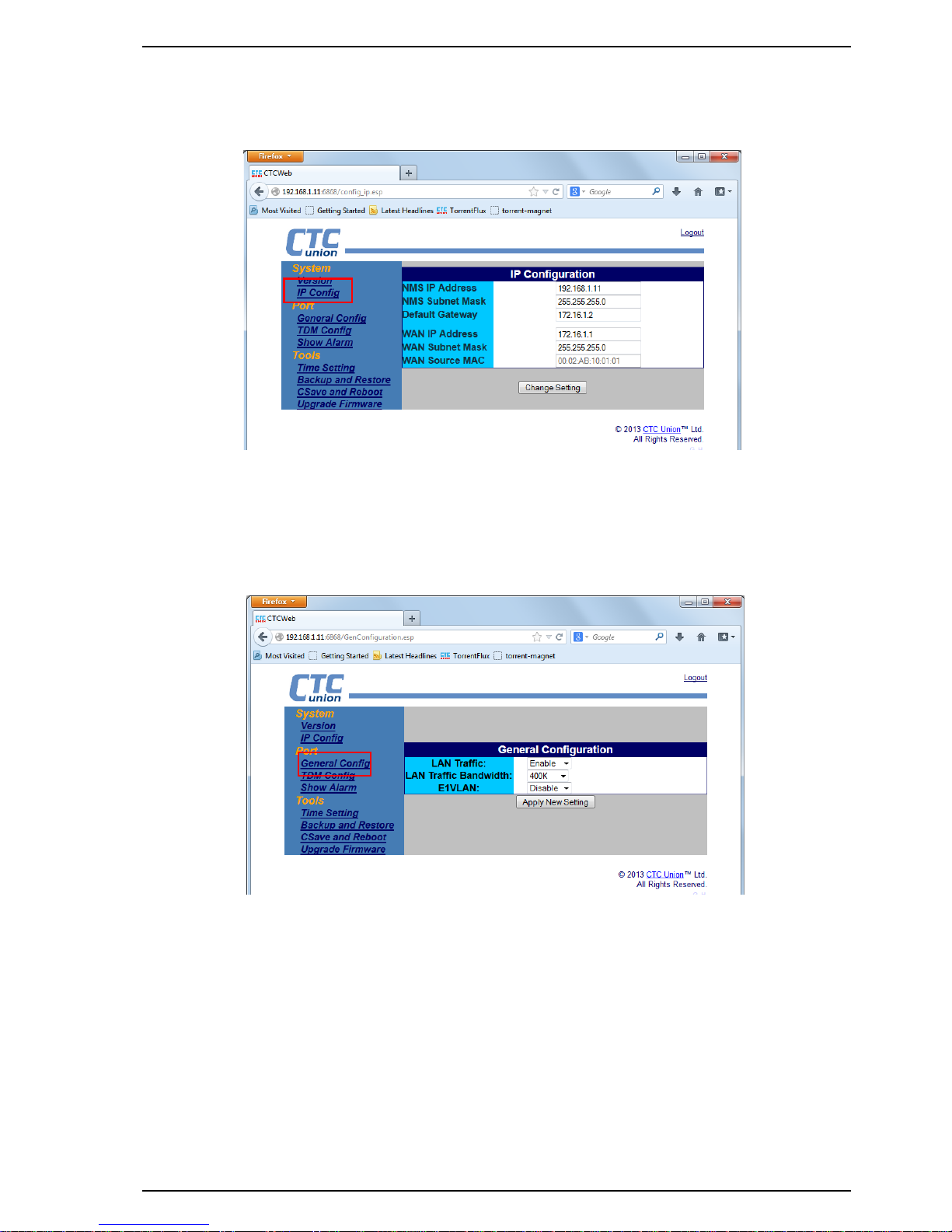
Change the NMS management IP address, subnet mask and gateway as well as the WAN IP and subnet mask here.
Figure 3.10.3 NMS and WAN IP configuration page
3.10.2 Port General Configuration
Configure the local LAN port here to enable or disable traffic. If enabled, configure the maximum allowed LAN traffic
speed. Enable or disable the E1 VLAN function here. The actual VID settings are performed under the "TDM Config"
screen.
Figure 3.10.4 General configuration page
Page 20
Chapter 3 Configuration and Operation
20
3.10.3 TDM Configuration
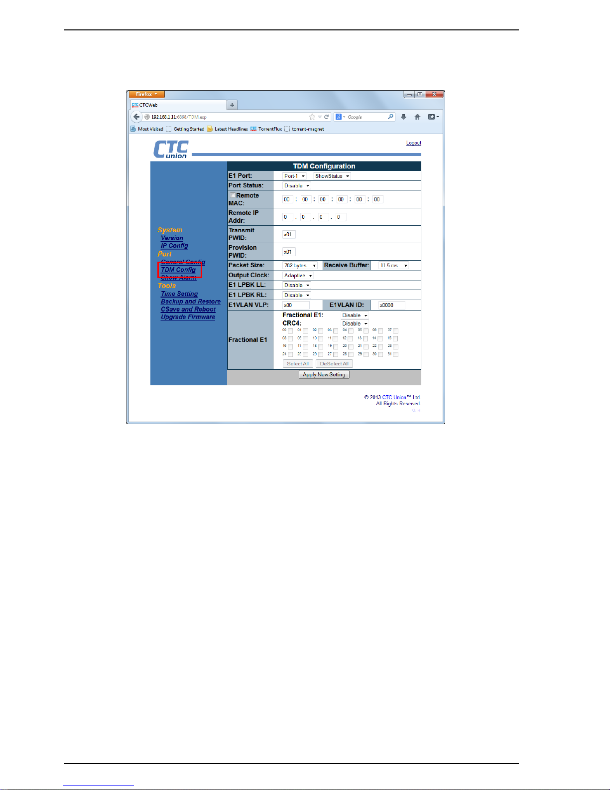
This page is the heart of the TDM configuration for the IPMux.
Figure 3.10.5 TDM configuration page
E1 Port : Chose the port to be configured from the pull-down
Port Status : Enable or Disable the E1 port
Remote MAC : Enter the MAC address of the remote E1 port for connection
Remote IP Addr : Enter the IP address of the remote WAN.
Transmit PWID : Enter the pseudo-wire ID.
Provision PWID : Enter the pseudo-wire ID for provisioning
Packet Size : Adjust the packet size of the TDMoIP packets. Larger packets have better utilization, smaller packets less
latency. This setting is a trade-off that depends on the network quality.
Receive Buffer : Adjust the jitter buffer to compensate for network latency. (Buffer must be more than latency)
Output Clock : Select the E1 clock type (Adaptive=packet recovery, RxLine=E1 recovery, Internal=OSC timing).
E1 LPBK LL : Disable or Enable E1 local loop back
E1 LPBK RL : Disable or Enable E1 remote loop back
E1VLAN VLP : Sets the VLAN tag's priority bits (0~7)
E1VLAN ID : Configured the VLAN ID for CeS traffic
Fractional E1 : Configure fractional E1 with or without CRC to reduce packet traffic when only fractional E1 is required.
When fractional E1 is enabled, individual timeslots are selected by checkboxes.
Page 21
Chapter 3 Configuration and Operation
21
3.10.4 Alarm History Display
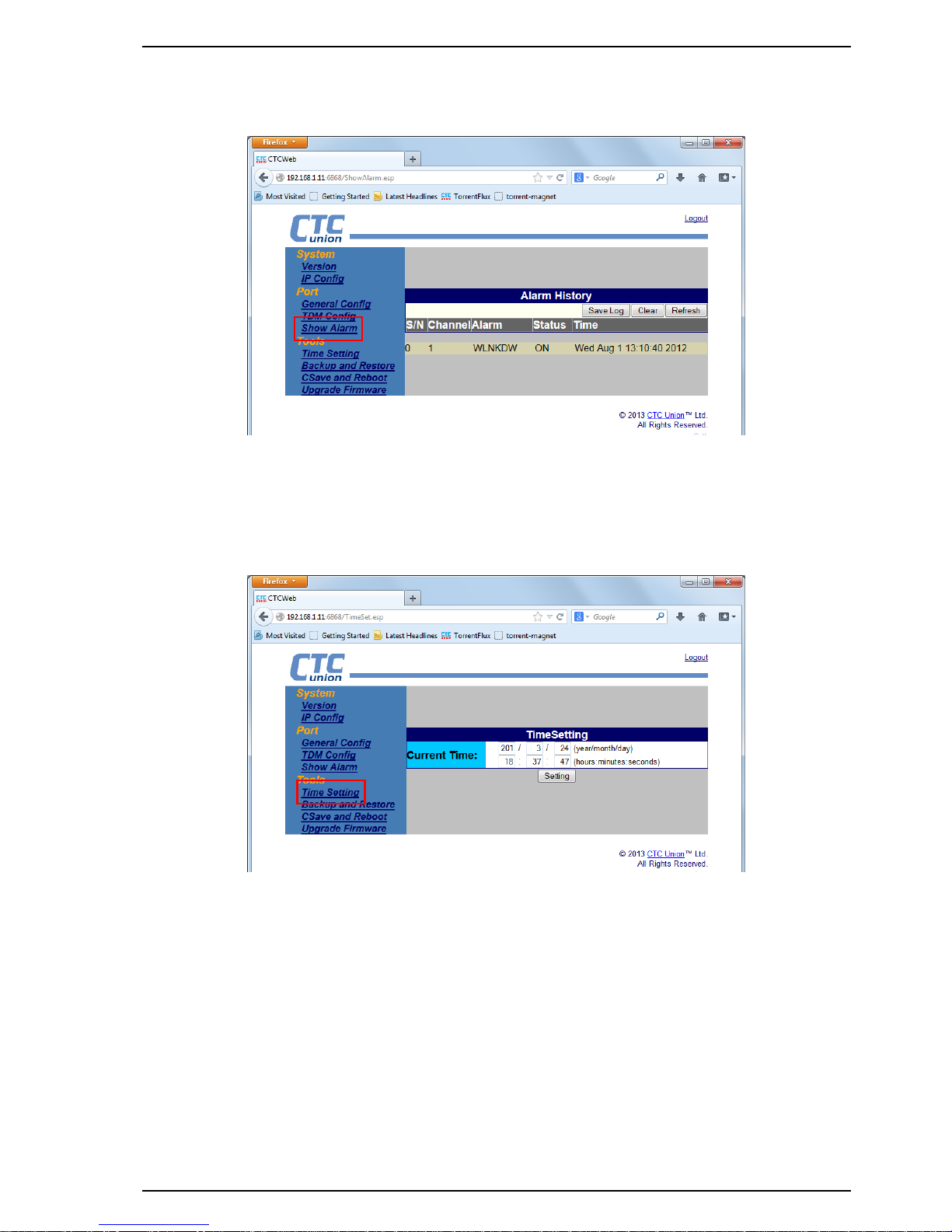
Alarm history is a read-only display. The screen supports refreshing, clearing or exporting the alarm log.
Figure 3.10.6 Alarm History page
3.10.5 Time Configuration
Select each parameter field, key in the correct value, press [Enter]. After finishing all fields, click "Setting".
Figure 3.10.7 Time Setting page
Page 22
Chapter 3 Configuration and Operation
22
3.10.6 Backup & Restore Configuration
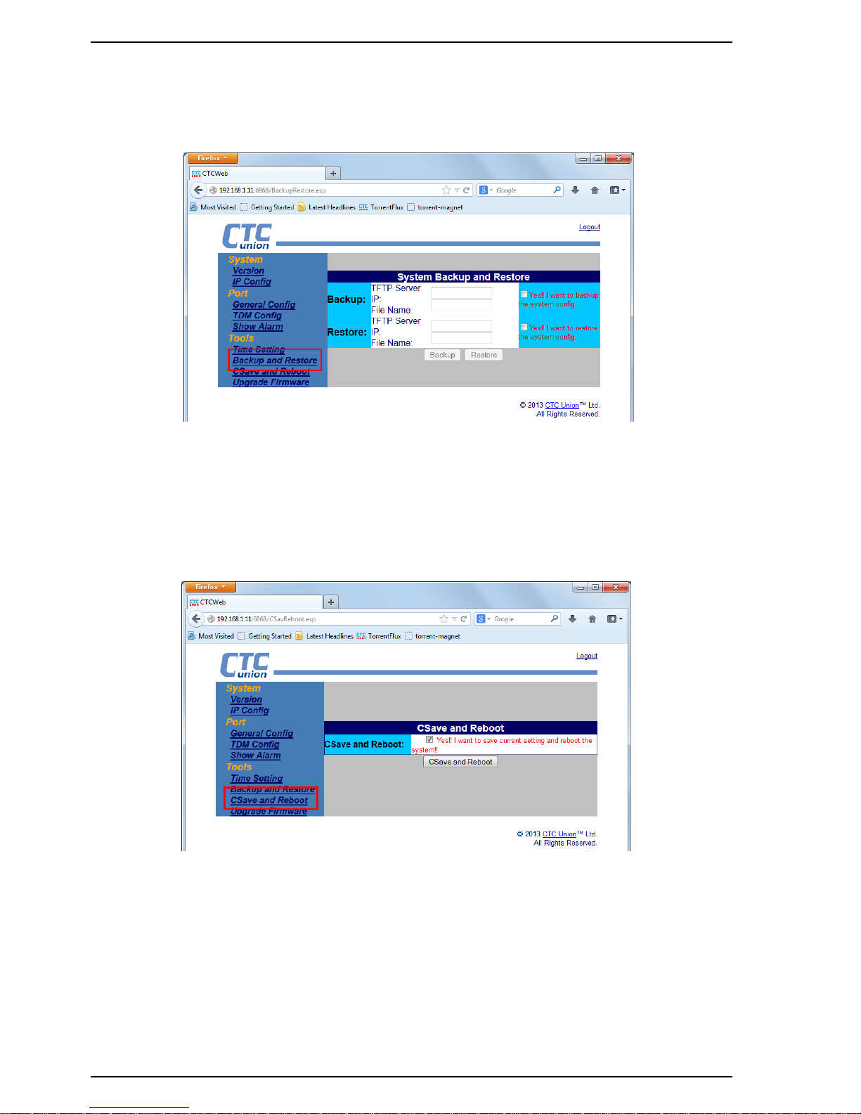
The IPMux provides backup and restore of system configuration via TFTP server. Enter the TFTP server's IP address
and the configuration filename (case sensitive), select the appropriate check box and function button.
Figure 3.10.8 Backup and Restore page
3.10.7 Save and Reboot Configuration
The Csave and Reboot page lets the configuration changes be stored in non-volatile storage and lets the IPMux
reboot with the new, saved configuration.
Figure 3.10.9 Save and Reboot page
Page 23
Chapter 3 Configuration and Operation
23
3.10.8 Firmware Upgrade
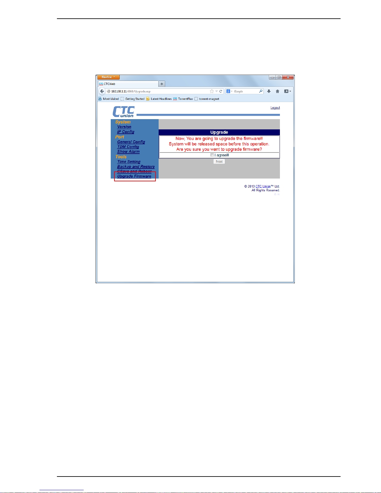
Occasionally, updated firmware may become available to add features or fix previously unknown issues. The
upgrade method uses TFTP server to transfer new image to the IPMux. The new image is then written to the flash and
will be available at next reboot.
Figure 3.10.10 Firmware Upgrade page
Warning: During firmware upgrade the flash memory will be erased prior to being written with the new
firmware image. Any interruption during this process will result in a 'bricked' device. Upgrading must be done with
reliable power provided and should only be attempted when instructed by the manufacturer.
Page 24

Appendix A
24
Appendix
A) Script for resetting IPMux to default I
Script for setting the device back to default I ( LAN bandwidth is 400 kbps)
Script for setting CO site configuration back to default I
#Execute global chip initialization
gci
#Configure an ip address for the WAN port
srcnet 172.16.1.1 255.255.255.0
#Configure an ip address and gateway for the NMS port
ipset 192.168.1.11 255.255.255.0 172.16.1.2
#Enable LAN port and set the bandwidth to 400Kbps.
lanset 1 7
#Save the configuration csave
Script for setting CPE site configuration back to default I
gci
srcnet 172.16.1.2 255.255.255.0
ipset 192.168.2.11 255.255.255.0 172.16.1.1
lanset 1 7
csave
B) Script for resetting IPMux to default II
Script for setting the device back to default II
(Enable E1 port#1 and set LAN bandwidth to 400 kbps)
Script for setting CO site configuration back to default II
gci
srcnet 172.16.1.1 255.255.255.0
ipset 192.168.1.11 255.255.255.0 172.16.1.2
#Set both transmitting and receiving pseudowire ID to 1 for E1 port#1
cespwidset 1 1 1
#Set the transmit packet size to 782 byte for E1 port#1
#Usage: pktsize ch_no pkt_size(0~3) !
#pkt_size(total len)=> (0: 1514 Byte, 1:782 Byte,
# 2: 178 Byte, 3: 306 Byte)
pktsize 1 1
#Set the jitter buffer depth to 11.5 msec for E1 port#1
#Usage: jitterbd ch_no depth !
#depth(pktsize=0)(0: 11 ms, 1: 23 ms, 2: 40 ms, 3: 75 ms,
# 4: 99 ms, 5: 145 ms, 6: 192 ms, 7: 239 ms ).
# since the packet size is set to 1 (782 Bytes) which is about half
# length of 1514 Bytes, the jitter buffer depth for packet size of
# 782 bytes will be 23msec/2 = 11.5msec
jitterbd 1 1
#Set the transmit clock source to RxLine for E1 port#1
#Usage: ceschclkset ch_num clksrc(0:Adaptive/1:Internal/2:RxLine)
ceschclkset 1 2
#Enable E1 port #1, and specifically set the destination IP and MAC
#address of the remote device (CPE).
ceschset 1 1 172.16.1.2 00:02:ab:10:01:02
lanset 1 7
csave
Page 25

Appendix A
25
Script for setting CPE site configuration back to default II
gci
srcnet 172.16.1.2 255.255.255.0
ipset 192.168.2.11 255.255.255.0 172.16.1.1
cespwidset 1 1 1
pktsize 1 1
jitterbd 1 1
ceschclkset 1 0
ceschset 1 1 172.16.1.1 00:02:AB:10:01:01
lanset 1 7
csave
C) Script for resetting IPMux to default III
Script for setting the device back to default III
(Enable E1 port#1 and port#2 and set LAN bandwidth to 400 kbps)
Script for setting CO site configuration back to default III
gci
srcnet 172.16.1.1 255.255.255.0
ipset 192.168.1.11 255.255.255.0 172.16.1.2
#Set both transmitting and receiving pseudowire ID to 1 for E1 port#1
#Set both transmitting and receiving pseudowire ID to 2 for E1 port#2
cespwidset 1 1 1
cespwidset 2 2 2
#Set the transmit packet size to 782 byte for both E1 port#1 and
# port#2.
pktsize 1 1
pktsize 2 1
#Set the jitter buffer depth to 11.5msec for both E1 port#1 and
# port#2.
jitterbd 1 1
jitterbd 2 1
#Set the transmit clock source to RxLine for both E1 port#1 and
# port#2.
ceschclkset 1 2
ceschclkset 2 2
#Enable both E1 port#1 and port#2, and specifically set the #destination IP and MAC address of the remote device
(CPE).
ceschset 1 1 172.16.1.2 00:02:ab:10:01:02
ceschset 2 1 172.16.1.2 00:02:ab:10:01:02
lanset 1 7
csave
Script for setting CPE site configuration back to default III
gci
srcnet 172.16.1.2 255.255.255.0
ipset 192.168.2.11 255.255.255.0 172.16.1.1
cespwidset 1 1 1
cespwidset 2 2 2
pktsize 1 1
pktsize 2 1
jitterbd 1 1
jitterbd 2 1
ceschclkset 1 0
ceschclkset 2 0
ceschset 1 1 172.16.1.1 00:02:ab:10:01:01
ceschset 2 1 172.16.1.1 00:02:ab:10:01:01
lanset 1 7
Page 26

Appendix A
26
csave
D) Script for resetting IPMux to default IV
Script for setting the device back to default IV (Enable E1 port #1 to #4 and set LAN bandwidth to 400kbps)
Script for setting CO site configuration back to default IV
gci
srcnet 172.16.1.1 255.255.255.0
ipset 192.168.1.11 255.255.255.0 172.16.1.2
#Set both transmitting and receiving pseudowire ID to 1 for E1 port#1
#Set both transmitting and receiving pseudowire ID to 2 for E1 port#2
#Set both transmitting and receiving pseudowire ID to 3 for E1 port#3
#Set both transmitting and receiving pseudowire ID to 4 for E1 port#4
cespwidset 1 1 1
cespwidset 2 2 2
cespwidset 3 3 3
cespwidset 4 4 4
#Set the transmit packet size to 782 byte for E1 port#1 to
# port#4.
pktsize 1 1
pktsize 2 1
pktsize 3 1
pktsize 4 1
#Set the jitter buffer depth to 11.5msec for E1 port#1 to
# port#4.
jitterbd 1 1
jitterbd 2 1
jitterbd 3 1
jitterbd 4 1
#Set the transmit clock source to RxLine for E1 port#1 to
# port#4.
ceschclkset 1 2
ceschclkset 2 2
ceschclkset 3 2
ceschclkset 4 2
#Enable E1 port#1 to port#4, and specifically set the destination
#IP and MAC address of the remote device (CPE).
ceschset 1 1 172.16.1.2 00:02:ab:10:01:02
ceschset 2 1 172.16.1.2 00:02:ab:10:01:02
ceschset 3 1 172.16.1.2 00:02:ab:10:01:02
ceschset 4 1 172.16.1.2 00:02:ab:10:01:02
lanset 1 7
csave
Script for setting CPE site configuration back to default IV
gci
srcnet 172.16.1.2 255.255.255.0
ipset 192.168.2.11 255.255.255.0 172.16.1.1
cespwidset 1 1 1
cespwidset 2 2 2
cespwidset 3 3 3
cespwidset 4 4 4
pktsize 1 1
pktsize 2 1
pktsize 3 1
pktsize 4 1
jitterbd 1 1
Page 27

Appendix A
27
jitterbd 2 1
jitterbd 3 1
jitterbd 4 1
ceschclkset 1 0
ceschclkset 2 0
ceschclkset 3 0
ceschclkset 4 0
ceschset 1 1 172.16.1.1 00:02:ab:10:01:01
ceschset 2 1 172.16.1.1 00:02:ab:10:01:01
ceschset 3 1 172.16.1.1 00:02:ab:10:01:01
ceschset 4 1 172.16.1.1 00:02:ab:10:01:01
lanset 1 7
csave
E) Script for resetting IPMux to default V
Script for setting the device back to default V (Enable E1 port#1 as Fractional E1
[10 timeslots] and set LAN bandwidth to 400 Kbps)
Script for setting CO site configuration back to default V
gci
srcnet 172.16.1.1 255.255.255.0
ipset 192.168.1.11 255.255.255.0 172.16.1.2
cespwidset 1 1 1
pktsize 1 1
jitterbd 1 1
ceschclkset 1 2
#Enable E1 port#1 to the fractional E1 mode
cesfe1mode 1 1
#Configure 10 timeslots allocated to the fractional E1 port#1
cesfe1tsmap 1 x7FE
ceschset 1 1 172.16.1.2 00:02:ab:10:01:02
lanset 1 7
csave
Script for setting CPE site configuration back to default V
gci
srcnet 172.16.1.2 255.255.255.0
ipset 192.168.2.11 255.255.255.0 172.16.1.1
cespwidset 1 1 1
pktsize 1 1
jitterbd 1 1
ceschclkset 1 0
cesfe1mode 1 1
cesfe1tsmap 1 x7FE
ceschset 1 1 172.16.1.1 00:02:ab:10:01:01
lanset 1 7
csave
F) Script for enable or disable order wire function
E1 channel # 5 is reserved for transmitting order wire packets. Before you execute the following commands, make
sure that the WAN port has been configured. Please refer to Appendix A on how to configure WAN port IP address.
Script for enable order wire at CO site
#Set transmitting and receiving pseudowire ID to 5 for E1 port#5
cespwidset 5 5 5
#Enable E1 port#5, and specifically set the destination IP and MAC
#addresses of the remote device (CPE).
ceschset 5 1 172.16.1.2 00:02:ab:10:01:02
csave
Page 28

Appendix A
28
Script for enable order wire at CPE site
#Set transmitting and receiving pseudowire ID to 5 for E1 port#5
cespwidset 5 5 5
#Enable E1 port#5, and specifically set the destination IP and MAC
#addresses of the remote device (CO).
ceschset 5 1 172.16.1.1 00:02:ab:10:01:01
csave
Script for disable order wire at both CO and CPE sites
#Disable E1 port#5 to stop transmitting order wire packets.
ceschset 5 0
csave
Page 29

Revision History
Version
Date
Descriptions
2.1
2014/7/3
Change factory defaults title to ~~CO/CPE device settings
CO Device (Factory Defaults)
Last page image (remove certificate logos)
Page 30

 Loading...