

Page 1
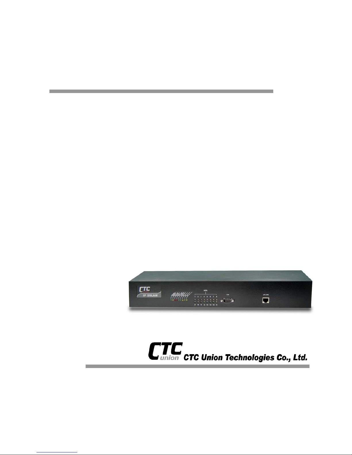
USER MANUAL
IP DSLAM for ADSL
IPDSLAM-A8/A16
Page 2

TABLE OF CONTENTS
List of Figures.................................................................................... vi
List of Tables..................................................................................... vii
About This Manual.............................................................................. 1
What’s the difference between ATM based DSLAM and IP based
DSLAM?............................................................................................... 3
1. Introduction................................................................................... 5
1.1 General.........................................................................................................5
1.2 ADSL IP DSLAM Overview .........................................................................6
1.3 ADSL IP DSLAM Application......................................................................9
1.4 ADSL IP DSLAM Features ........................................................................10
1.5 ADSL IP DSLAM Specifications...............................................................11
2. Getting Started............................................................................ 12
2.1 General.......................................................................................................12
2.2 Unpacking your ADSL IP DSLAM.............................................................13
2.3 Hardware Installation................................................................................14
Safety Instruction............................................................................................................14
ADSL IP DSLAM Rear Panel Connection......................................................................15
ADSL IP DSLAM Front Panel Connection......................................................................16
2.4 Ways of Management Connection...........................................................17
Embedded Web Interface(EmWeb)................................................................................17
Command Line Interface (CLI).......................................................................................17
Telnet Client....................................................................................................................18
3. System Administration with EmWeb ........................................ 19
3.1 Log In with Embedded Web Interface......................................................19
3.2 Embedded Web Interface Menu...............................................................20
3.3 Default (Factory) Configuration Settings {Default Setting}...................23
3.4 Displaying the System Information of your ADSL IP DSLAM {System
Information}..........................................................................................................24
3.5 Save your Configuration to Flash {Save to Flash}.................................25
Page 3

iii
3.6 Displaying Current Event {Current Event}..............................................26
3.7 Configuring ADSL IP DSLAM ...................................................................28
Configuring Port Filtering {Set Port Filter} ......................................................................28
Configuring IP and Location {System IP / Location}.......................................................29
Configuring Date and Time {System Date and Time}.....................................................30
Changing your Password {Changing Password}............................................................30
3.8 DSL Line Configuration............................................................................31
Creating a Line Profile {Create Line Profile}...................................................................31
Creating a Alarm Profile {Create Alarm Profile} ...........................................................32
Displaying and Modifying a Line Profile {Current Line Profile}.......................................33
Displaying and Modifying a Alarm Profile {Current Alarm Profile} ..................................34
3.9 Port Configuration ....................................................................................35
DSL Port Configuration{DSL Port Configuration}............................................................35
PVC Configuration{PVC Configuration}..........................................................................36
List of Subscriber {List of Subscriber}.............................................................................38
Routing Table {Routing Table} ........................................................................................39
3.10 Management Configuration......................................................................40
Configuring SNMP Access Parameters and Trap IPs {SNMP}.......................................40
Configuring Management IP {Management IP}..............................................................41
3.11 Performance Monitor................................................................................42
ADSL Physical Layer PM {Physical Layer Info}..............................................................42
ADSL Channel Layer PM {Channel Layer Info}..............................................................43
ADSL Physical Layer PM within Current 15 Minutes and a Day Duration {Current
Phy-Layer PM}................................................................................................................44
ADSL Channel Layer PM within Current 15 Minutes and a Day Duration {Current
Channel-Layer PM} ........................................................................................................46
ADSL Physical Layer PM within Previous 15 Minutes Duration {15 MIN Phy-Layer PM}
........................................................................................................................................47
ADSL Physical Layer PM within Previous 1 Day Duration {1 DAY Phy-Layer PM}........48
ADSL Channel Layer PM within Previous 15 Minutes Duration {15 MIN Channel-Layer
PM}.................................................................................................................................49
ADSL Channel Layer PM within Previous 1 Day Duration {1 DAY Channel-Layer PM}.50
3.12 Miscellanea................................................................................................51
IGMP Snooping Configuration {IGMP_Snooping Config}...............................................51
IGMP Snooping Status {IGMP_Snooping Status} ..........................................................51
SNTP Status {SNTP Status}...........................................................................................53
4. System Administration with CLI................................................ 55
4.1 Command Structure..................................................................................55
Calling Commands.........................................................................................................60
4.2 General Configuration ..............................................................................61
4.3 Event Viewing and Deleting .....................................................................62
Displaying the Current Event..........................................................................................62
Page 4

iv
Deleting the Event of ADSL IP DSLAM ..........................................................................62
Reset Port.......................................................................................................................62
Restart the ADSL IP DSLAM..........................................................................................63
Resetting all Configurations to Default Setting...............................................................63
System Upgrade.............................................................................................................63
Logging Out your ADSL IP DSLAM................................................................................64
4.4 Configuring Y our ADSL IP DSLAM ..........................................................64
System Configuration.....................................................................................................64
Port-Filtering Configuration.............................................................................................66
IP Configuration..............................................................................................................67
Time Configuration.........................................................................................................68
SNTP configuration ........................................................................................................69
Changing the Password .................................................................................................70
4.5 Configuring DSL........................................................................................71
Creating Line Profile and Alarm Profile...........................................................................71
Modifying DSL Profile and Alarm Profile.........................................................................74
Deleting a DSL Profile and Alarm Profile........................................................................75
Displying a DSL Profile and Alarm Profile.......................................................................76
4.6 Port Configuration ....................................................................................79
Enabling and Disabling a port.........................................................................................79
Attaching DSL Profile......................................................................................................79
Displaying the Current Status and Information of ADSL Line.........................................80
PVC Configuration..........................................................................................................81
Subscriber Configuration................................................................................................85
Routing Table configuration............................................................................................87
4.7 Management Configuration......................................................................89
Configuring SNMP Access Parameters..........................................................................89
Configuring Trap IP.........................................................................................................90
Configuring Management IP...........................................................................................91
Displaying Management IP.............................................................................................91
Deleting Management IP................................................................................................92
4.8 IGMP configuration...................................................................................93
Displaying IGMP Status..................................................................................................93
Displaying IGMP Group..................................................................................................94
Configuring IGMP...........................................................................................................94
4.9 Performance Monitor................................................................................95
Displaying the Physical Layer Information...................................................................95
Displaying the Channel Layer Information......................................................................96
Displaying Physical Performance Statistics within Current 15 Minutes and 1 Day Duration
........................................................................................................................................96
Displaying Channel Performance Statistics within Current 15 Minutes and 1 Day Duration
........................................................................................................................................98
Displaying Physical Performance Statistics durin g Previous 15 Minutes or 1 Day Duration
......................................................................................................................................100
Displaying Channel Performance Statistics durin g Previous 15 Minutes or 1 Day Duration
......................................................................................................................................101
Page 5

v
4.10 Ethernet Rate Mode Configuration........................................................102
Show Ethernet Rate Mode ...........................................................................................102
Modifying Ethernet Rate Mode.....................................................................................102
4.11 DHCP Server Configuration ...................................................................103
Show DHCP Sever Configuration.................................................................................103
Modifying DHCP Server ...............................................................................................103
4.12 Configuring User Account......................................................................104
Creating User Account..................................................................................................104
Modifying User Account................................................................................................106
Displaying the Information of User Account..................................................................106
4.13 Deleting User Account............................................................................107
5. Configuration Backup and Restore ........................................ 108
5.1 Configuration Restore ............................................................................109
5.2 ADSL IP DSLAM upgrade procedure..................................................... 111
5.3 IP DSLAM rescue procedure while system crashed............................112
6. Troubleshooting.........................................................................116
Problems with Starting up ADSL IP DSLAM.................................................................117
Problems with Configuration.........................................................................................117
Problems with SNMP.................................................................................................... 118
Problems with Telnet ....................................................................................................118
Problems with Password.............................................................................................. 118
Appendix-A: Pin Assignment.............................................................. I
Appendix-B The SNTP timezone abbrivation..................................IV
Appendix-C The Default Setting of ADSL IP DSLAM.....................VII
Glossary............................................................................................VIII
Page 6

vi
List of Figures
Figure 0-1 PPPoE application in Traditional ATM-based ADSL Network.......................3
Figure 0-2 PPPoE application in ADSL IP DSLAM with Ethernet-All-The-Way Network4
Figure 1-1 ADSL IP DSLAM Front View ........................................................................6
Figure 1-2 ADSL IP DSLAM Rear View.........................................................................7
Figure 1-3 ADSL IP DSLAM LED Identification .............................................................7
Figure 2-1 ADSL IP DSLAM Rear Panel Connection ..................................................15
Figure 2-2 ADSL IP DSLAM Front Panel Connections................................................16
Page 7

List of Tables
Table 1-1 ADSL IP DSLAM LED Description.................................................................8
Table 3-1 Sysinfo field definition ..................................................................................24
Table 3-2 Event log description....................................................................................26
Table 3-3 Create Line Profile Field Definitions.............................................................31
Table 3-4 Create Alarm Profile Field Definitions ..........................................................32
Table 3-5 PVC Configuration Field Definitions.............................................................36
Table 3-6 Physical Layer Info Field Definitions ............................................................42
Table 3-7 Channel Layer Information Field Definitions ................................................43
Table 3-8 Current Phy-Layer PM Information Field Definitions....................................44
Table 3-9 Current Channel-Layer PM Information Field Definitions.............................46
Table 3-10 15 MIN Phy-Layer PM Information Field Definition....................................47
Table 3-11 1-DAY Phy-Layer PM Information Field Definition......................................48
Table 3-12 15 MIN Phy-Layer PM Information Field Definition....................................49
Table 3-13 1 DAY Phy-Layer PM Information Field Definition......................................50
Table 3-14 IGMP Snooping Table Definition ................................................................52
Table 4-1 CLI Command - Action List ..........................................................................56
Table 4-2 CLI Command – Identifier List........................................................................56
Table 4-3 Relation between <action> and <identifier>.................................................57
Table 4-4 CLI Command – Parameter List...................................................................57
Table 4-5 “show event” Field Definition........................................................................62
Table 4-6 Sysinfo field definition ..................................................................................65
Table 4-7 “show portfilter” Filed Definition....................................................................66
Table 4-8 Sysip Field Definition....................................................................................67
Table 4-9 Time Field Definition.....................................................................................68
Table 4-10 “show lineprof” Field Definition...................................................................76
Table 4-11 “show alarmprof” Field Definition................................................................77
Table 4-12 “show port” Field Definition ........................................................................80
Table 4-13 “show adslline” Field Definition ..................................................................81
Table 4-14 Ways of PVC configuration either with VLAN tag or without VLAN tag......82
Table 4-15 “show connection” Field Definition .............................................................84
Table 4-16 “show vid” Field Definition..........................................................................85
Table 4-17 “show subscriber” Field Definition..............................................................85
Table 4-18 “show snmp” Field Definition......................................................................89
Table 4-19 “show trapdest” Field Definition..................................................................90
Table 4-20 “show manip” Field Definition.....................................................................92
Table 4-21 “show adslphysical” Field Definition...........................................................95
Table 4-22 “show adslchannel” Field Definition” ..........................................................96
Table 4-23 “show adslphperf” Field Definition..............................................................97
Table 4-24 “show adslchperf” Field Definition..............................................................99
Table 4-25 “show adslphintl” Field Definition .............................................................100
Table 4-26 “show adslchintl” Field Definition..............................................................101
Table 4-27 “show dhcpd” Field Definition...................................................................103
Table 7-1 Troubleshooting the Start-up your ADSL IP DSLAM.................................. 117
Table 7-2 Troubleshooting the ADSL IP DSLAM configured setting.......................... 117
Table 7-3 Troubleshooting the SNMP server.............................................................118
Table 7-4 Troubleshooting Telnet............................................................................... 118
Table 7-5 Troubleshooting the password...................................................................118
T able A-1 ADSL IP DSLAM CID port pin assignment...................................................I
T able A-2 Null modem cable pin assignment (for PC to CID port connection).............I
T able A-3 ADSL IP DSLAM uplink port pin assignment ...............................................I
Page 8

Introduction
viii
T able A-4 Uplink and downlink port (Xn) pin assignment............................................II
T able A-5 8 ports ADSL LINE Connector pin assignment...........................................II
T able A-6 8 ports POTS splitter PHONE Connector pin assignment ..........................II
Page 9

ADSL IP DSLAM
1
About This Manual
Audience
This book is intended for anyone who installs, manages, and configures the
ADSL IP DSLAM, one product of ADSL IP DSLAM Series, via CID/RS-232 or
Telnet/Ethernet CLI command interface. The ADSL IP DSLAM is a standalone
IP-based DSLAM which can concentrate and manage 8/16 ADSL ports.
You must have a basic understanding of ADSL related technologies, be
knowledgeable about data communications, and familiar with VT-100 terminal
emulation tools.
Purpose
This book describes how to install, manage, and configure the ADSL IP
DSLAM system via CLI command Line interface through CID/RS-232 interface
or Telnet/Ethernet interface.
Organization
This book provides task-based instructions for installing and using the CLI
interface to configure and administrate the ADSL IP DSLAM System. The
manual is organized as follows:
Chapter Title & Description
1
Introduction
Provides an overview of ADSL IP DSLAM System, including
features, fucntions, applications of the ADSL IP DSLAM.
2
Getting Started
Presents platform and system requirements as well as
procedures and instructions for installing the ADSL IP DSLAM.
3
System Administration with EmWeb
Provides all the instructions and procedures necessary for you to
administer your ADSL IP DSLAM with EmWeb interface.
4
System Administration with CLI
Provides all the instructions and procedures necessary for you to
Administer your ADSL IP DSLAM with CLI interface.
5
Configuration Back Up, Restore,Update and Rescue
Provides the procedures to back up configuration settings from
ADSL IP DSLAM and restore to ADSL IP DSLAM. Moreover, the
upade and rescue porcedures are also introduced.
Page 10

ADSL IP DSLAM
2
6
Troubleshooting
Provides some potential problems and possible remedies and
helps you diagnose and solve the problems.
7
Appendix A
Presents the pin assignment for ADSL IP DSLAM
8
Appendix B
Presents the SNTP time zone abbrivation.
9
Appendix C
Present the deafult settings of ADSL IP DSLAM
9
Glossary
Defines the key terms and acronyms mentioned in this maunal.
Document Conventions
Screen displays use these conventions:
# Login with Administrator privilege
% Login with operator privilege
> Login with guest privilege
Commands descriptions use these conventions:
[ ] Elements in square brackets are optional
< > Essential values
< x | y | z > Alternative keywords are grouped in < > and separated by
vertical bars
Others
Note
Means reader take note. Notes contain helpful suggestions.
Page 11
ADSL IP DSLAM
3
What’s the difference between ATM based
DSLAM and IP based DSLAM?
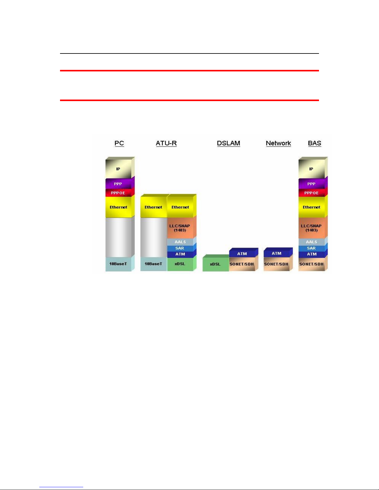
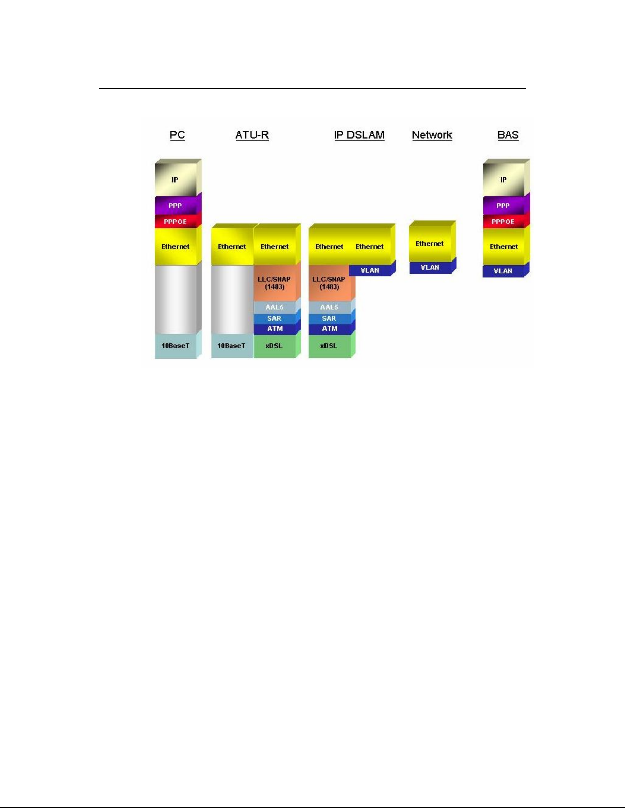
Fig 0-1 & Fig 0-2 display the differences between traditional ATM-based
DSLAM and ADSL IP DSLAM in PPPoE application sample.
Figure 0-1 PPPoE application in Traditional ATM-based ADSL Network
As Fig 0-1 displays, in traditional ATM-based ADSL network, the user
application information is encapsulated by ADSL CPE into ATM cells in
pre-defined VC(Virtual Channel, PVC), and then upstream the ATM cells to
DSLAM via ADSL link. (In this example, the user information (PPPoE
encapsulated) is encapsulated by ATU-R using RFC-1483 Bridge-mode
encapsulation format.)
All the ATM cells belong to the specified VC is concentrated by the DSLAM,
and switched in the ATM network clouds, to the defined destination (ISPs,
Offices, ..), at there the ATM cells and PPPoE frames is resolved by the
Broadband Access Server, and the user application information is serviced.
Page 12
ADSL IP DSLAM
4
Figure 0-2 PPPoE application in ADSL IP DSLAM with Ethernet-All-The-Way
Network
In addition to traditional ATM-based ADSL network. As Fig 0-2 displays, the
user application information is still encapsulated by ADSL CPE into ATM cells
in pre-defined VC (Virtual Channel, PVC), and then upstream the ATM cells to
DSLAM via ADSL link.
In the ADSL IP DSLAM, all the ATM cells belong to the specified VC are
decapsulated back to the original PPPoE encapsulated Ethernet packet (if
VLAN-mode of the specified ADSL port is disabled), or mapped to the
pre-defined Ethernet-VLAN packets (if VLAN-mode of the specified ADSL port
is enabled). ADSL IP DSLAM concentrates all Ethernet-with/without VLAN-tag
packets from 16 ports’ ADSL and uplinks to ISP’s Ethernet-All-The-Way
network. The PPPoE frames will be resolved at Broadband Access Server
(BAS), and the user application information was serviced.
The ADSL IP DSLAM supports ADSL CPE Bridge-mode (RFC-1483 Bridge
mode and router mode). For performance concern, ADSL IP DSLAM will not
act as BRAS to process user application information directly.
ADSL IP DSLAM provides Ethernet-with/without VLAN tag to ATM-PVC
mapping feature for the ISP to isolate user’s data with security and to provide
lots of service enhancement capabilities. ADSL IP DSLAM supports 2 ATM
PVC links for each ADSL CPE.
Page 13

ADSL IP DSLAM
5
1. Introduction
1.1 General
This chapter will help you understand the function and application of your
ADSL IP DSLAM. It covers
ADSL IP DSLAM Overview
This section describes the overview of your ADSL IP DSLAM. The ADSL IP
DSLAM is cost effective solution for you to complete immediate
implementation of multiple of services in private and public networks.
ADSL IP DSLAM Application
ADSL IP DSLAM can be applied in MTU/MDU/MHU and Ethernet-all-the-way
application.
ADSL IP DSLAM Features
This section describes the features of ADSL IP DSLAM and its specification.
Page 14
ADSL IP DSLAM
6
1.2 ADSL IP DSLAM Overview
Using the latest ADSL technology, ADSL IP DSLAM offers service providers a
very cost-effective solution for immediate implementation of multiple services
in private and public networks.
ADSL IP DSLAM can concentrate and manage up to 16 ADSL lines. User can
use local RS-232 CID and/or remote TELNET/SNMP to manage the ADSL IP
DSLAM directly
Since the ATM backbone coverage is not so general in the real broadband
network environment. Instead of traditional DSLAM system provides ATM
uplink interface, the ADSL IP DSLAM concentrates 8/16 ports of the ATM over
ADSL traffic which is encapsulated by ADSL CPEs, and maps each user’s
data encapsulated in ATM-PVC to Ethernet-with/without VLAN-tag packet
(depends on the VLAN was enabled or not for the specified ATM ports), and
then uplink to Telco or ISP directly, User can enable VLAN-PVC mapping
capability for each ADSL port independently. The ADSL IP DSLAM acts as
bridge for the ADSL ports without enabling the VLAN-PVC mapping feature.
ADSL IP DSLAM provides both Ethernet-VLAN and non-VLAN to ATM-PVC
mapping feature and bridge mode for the ISP to isolate user’s data with
security and to provide lots of service enhancement capabilities. ADSL IP
DSLAM supports 2 ATM PVC links for each ADSL CPE.
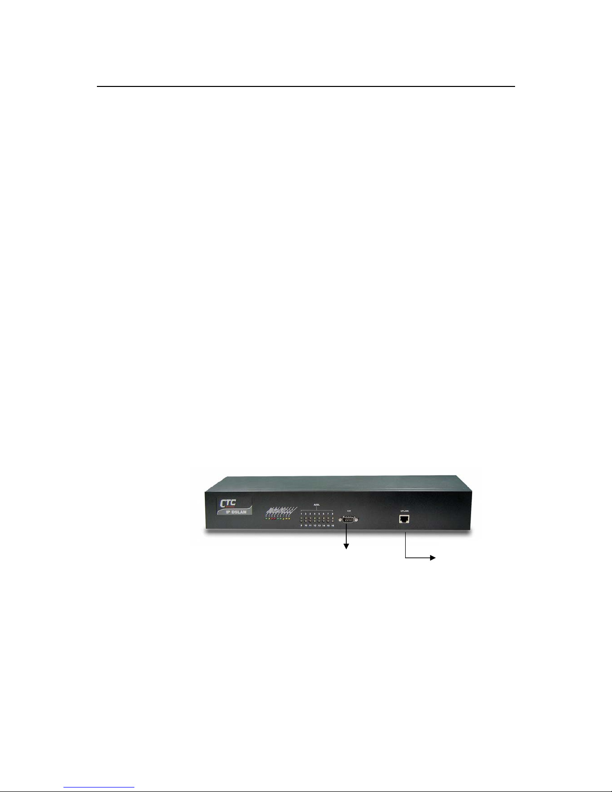
Figure 1-1 ADSL IP DSLAM Front View
As Fig 1-1 displays, in the front view of ADSL IP DSLAM, there are several
LEDs to indicate current system and link status and one 10/100 Mega Ethernet
interface for uplink.
The ADSL IP DSLAM can be managed via SNMP, but each ADSL IP DSLAM
will cost one IP address, and the performance of the ADSL IP DSLAM will be
little affected due to CPU usage for the SNMP agent processing.
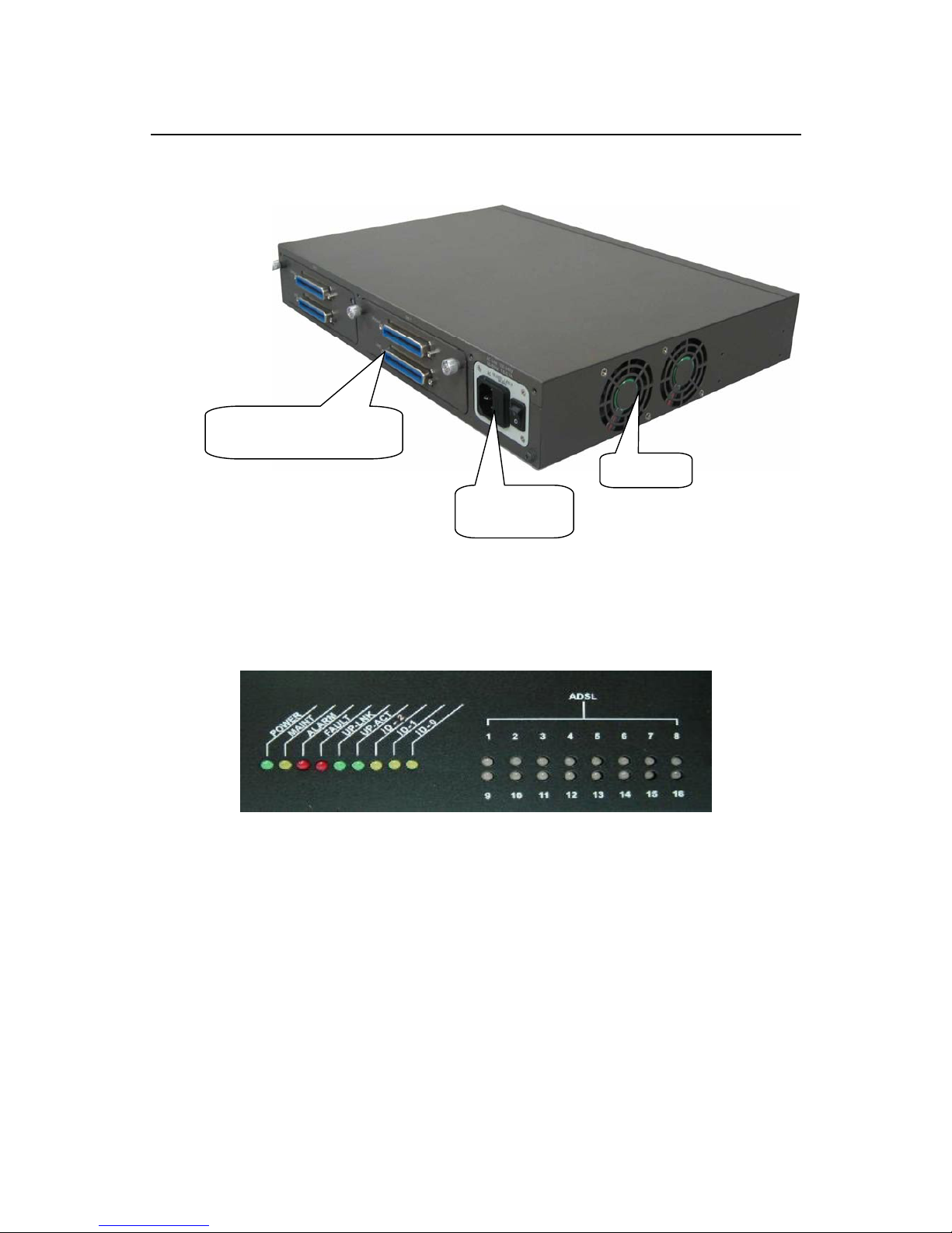
As Fig 1-2 displays, in the rear-panel, there is one power adaptor, both -42V ~
-56V DC or 90V ~ 240V AC power module can be selected. There are two DSL
module slots, each module provides 8-port with built-in POTS-splitter ADSL
module, totally 16 ADSL CPE users can be supported in one ADSL IP DSLAM.
CID
Fast Ethernet uplink
for uplink
Page 15
ADSL IP DSLAM
7
Figure 1-2 ADSL IP DSLAM Rear View
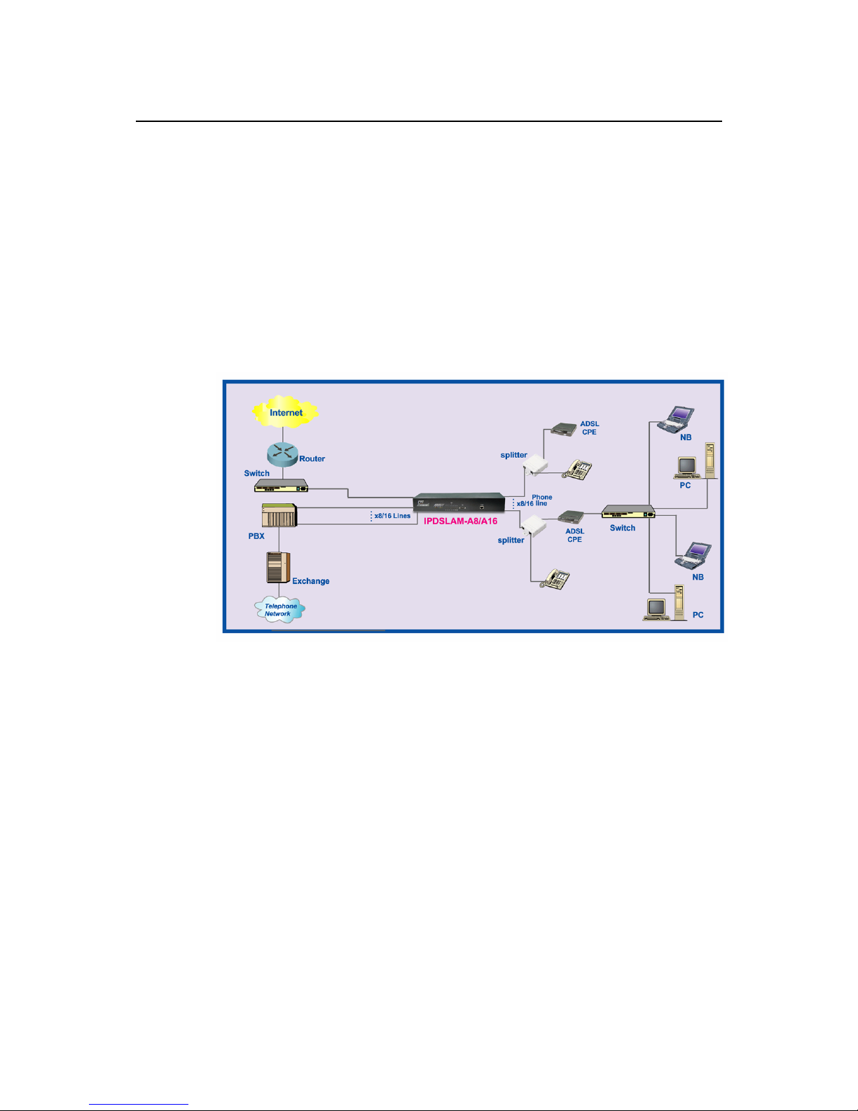
Fig 1-3 displays the LED identification of ADSL IP DSLAM, and Table-1
describes its color definition and status description.
Figure 1-3 ADSL IP DSLAM LED Identification
AC power
module
8-port ADSL module
with built-in splitter
Fan
Page 16

ADSL IP DSLAM
8
Table 1-1 ADSL IP DSLAM LED Description
<LED ID> Color Description
Power Green Lit when power on
Maint Green Lit when maintance commands were issued
Alarm Green Lit when MJ/MN events happen
Faullt Green Lit when system error is detected
Link Green Lit when Uplink Ethernet interface was connected
Act Green Blink when information is transmitted through uplink
Ethernet interface
ID-0 & ID-1 &
ID-2
Green ID0, ID1,ID2 : off off off ------when po wer on
ADSL1 –
ADSL16
Green/
Blinking
Orange/
No light/
Red
Lit Solid Green when ADSL link is in active state;
Lit Blinking Orange when the specified ADSL link is
in connection training state;
LED off when ADSL link is not in service
Lit Solid Red when loss of signal occurs
Note: Do not power off your ADSL IP DSLAM when LEDs “MAINT”,
“ALARM” and “FAULT” are blinking simultaneously.
Page 17
ADSL IP DSLAM
9
1.3 ADSL IP DSLAM Application
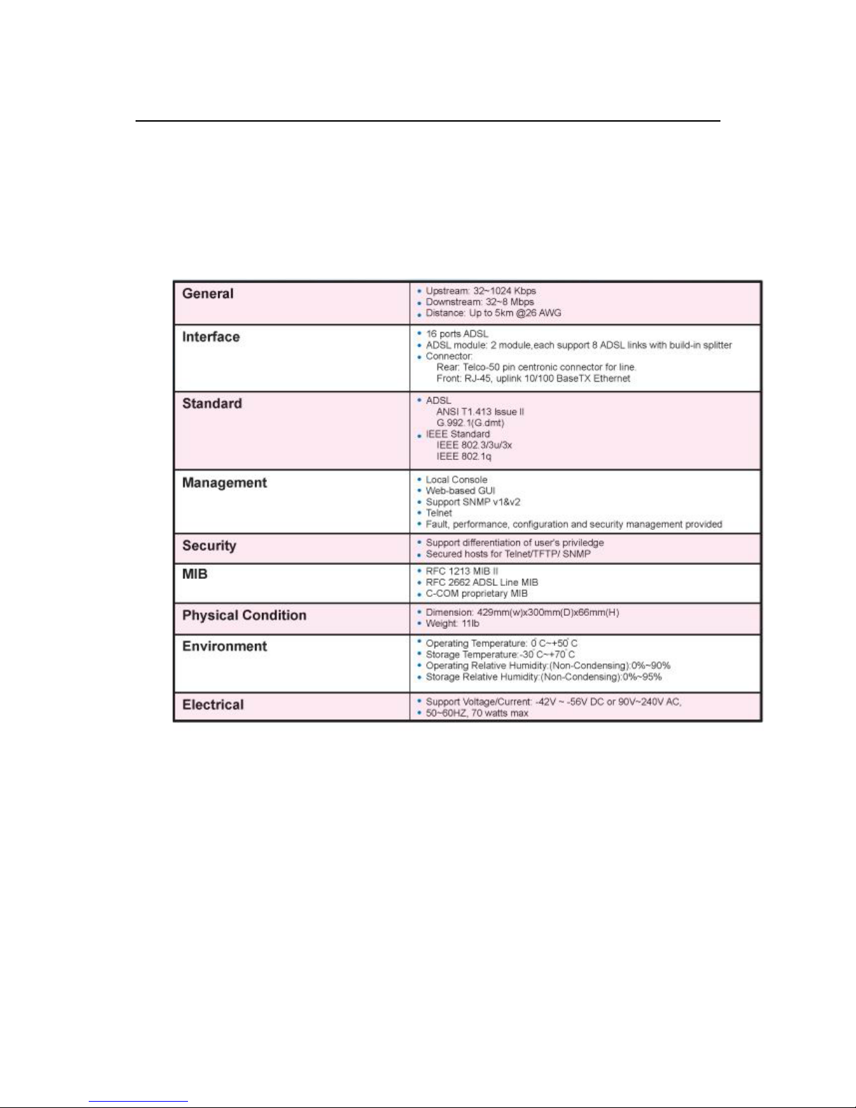
As the following figure shown, ADSL IP DSLAM consists of two network
modules. Each network module provides eight ADSL ports with built-in POTS
splitters so that it provides broadband data service over existing copper wires
without affecting the conventional voice service. ADSL IP DSLAM, therefore, is
a perfect solution for both central office co-location and MTU/MHU markets.
Page 18

ADSL IP DSLAM
10
1.4 ADSL IP DSLAM Features
VLAN support
The ADSL IP DSLAM supports mapping of Ethernet-VLAN to ATM-PVC
feature for security concern.
Compact design for limited space
The ADSL IP DSLAM occupies 1.5 U of standard Telco rack space. Its
compactness is perfect for collocation and basement installation. With the
built-in POTS splitters, service providers even no need to allocate extra space
for POTS splitter shelves.
Standalone System Design
For the area of less than 16 subscribers, network designer can use ADSL IP
DSLAM to provide service directly.
Page 19
ADSL IP DSLAM
11
1.5 ADSL IP DSLAM Specifications
Page 20

ADSL IP DSLAM
12
2. Getting Started
2
2.1 General
This chapter provides the installation instruction for the hardware installation
and system configuration of your ADSL IP DSLAM so that you can start up
quickly. It includes the following sections:
Unpacking your ADSL IP DSLAM
This section describes how to unpacking your ADSL IP DSLAM, and part
number explanation.
Hardware Installation
This section describes the power connection, loop connection and CID
connection.
Ways of management connection
This section describes how to engage in management connection by EmWeb,
CLI and Telnet.
Page 21

ADSL IP DSLAM
13
2.2 Unpacking your ADSL IP DSLAM
This section describes how to unpack your ADSL IP DSLAM. For a box of
ADSL IP DSLAM, there may contain the following materials:
1. ADSL IP DSLAM
2. Mounting bracket package
3. RJ-45 Ethernet cable
4. Power cord (AC power module only)
5. RS 232 cable to facilitate the connection between CID and PC
6. CD including user manaul and Quick Start Guide
7. A copy of Quick Start Guide
8. Accessory package
¾ Any other accessories requested at time of ordering.
Check the contents of the package and inspect the unit for any signs of
damage. Report any defects to vendor’s customer service representative.
Retain all packing materials for future shipment.
Page 22

ADSL IP DSLAM
14
2.3 Hardware Installation
• The ADSL IP DSLAM can be installed in a standard 19-inch rack, by using
the mounting brackets provided.
• Mount the shelf on the rack using the large screws provided.
• Follows the following procedures to connect and wire the system.
Safety Instruction
The following is the safety instructions for ADSL IP DSLAM before installation:
1. Read and follows all warning notices and instructions of this user manual.
2. The maximum recommended operating temperature for the ADSL IP
DSLAM is 50ºC. Care must be taken to allow sufficient air circulation or space
between units when the ADSL IP DSLAM is installed inside a closed rack
assembly and racks should safely support the combined weight of all ADSL IP
DSLAM.
3. The connections and equipment that supply power to the ADSL IP DSLAM
should be capable of operating safely with the maximum power requirements
of the ADSL IP DSLAM. In the event of a power overload, the supply circuits
and supply wiring should not become hazardous.
4. The AC adapter must plug in to the right supply voltage. Make sure that the
supplied AC voltage is correct and stable. If the input AC voltage is over 10%
lower than the standard may cause the ADSL IP DSLAM to malfunction.
5. Do not allow anything to rest on the power cord of the AC adapter, and do
not locate the product where anyone can walk on the power cord.
6. Generally, when installed after the final configuration, the product must
comply with the applicable safety standards and regulatory requirements of the
country in which it is installed. If necessary, consult for technical support.
7. A rare condition can create a voltage potential between the earth grounds of
two or more buildings. If products installed in separate building are
interconnected, the voltage potential can cause a hazardous condition.
Consult a qualified electrical consultant to determine whether or not this
phenomenon exists and, if necessary, implement corrective action before
interconnecting the products. If the equipment is to be used with
telecommunications circuit, take the following precautions:
Page 23
ADSL IP DSLAM
15
• Never install telephone wiring during a lightning storm.
• Never install telephone jacks in wet location unless the jack is specially
designed for wet location.
• Never touch uninsulated telephone wires or terminals unless the telephone
line has been disconnected at the network interface.
• Use caution when installing or modifying telephone lines (other than a
cordless telephone) during an electrical storm. There is a remote risk of electric
shock from lightning.
• Do not use a telephone or other equipment connected to telephone lines to
report a gas leak in the vicinity of the leak.
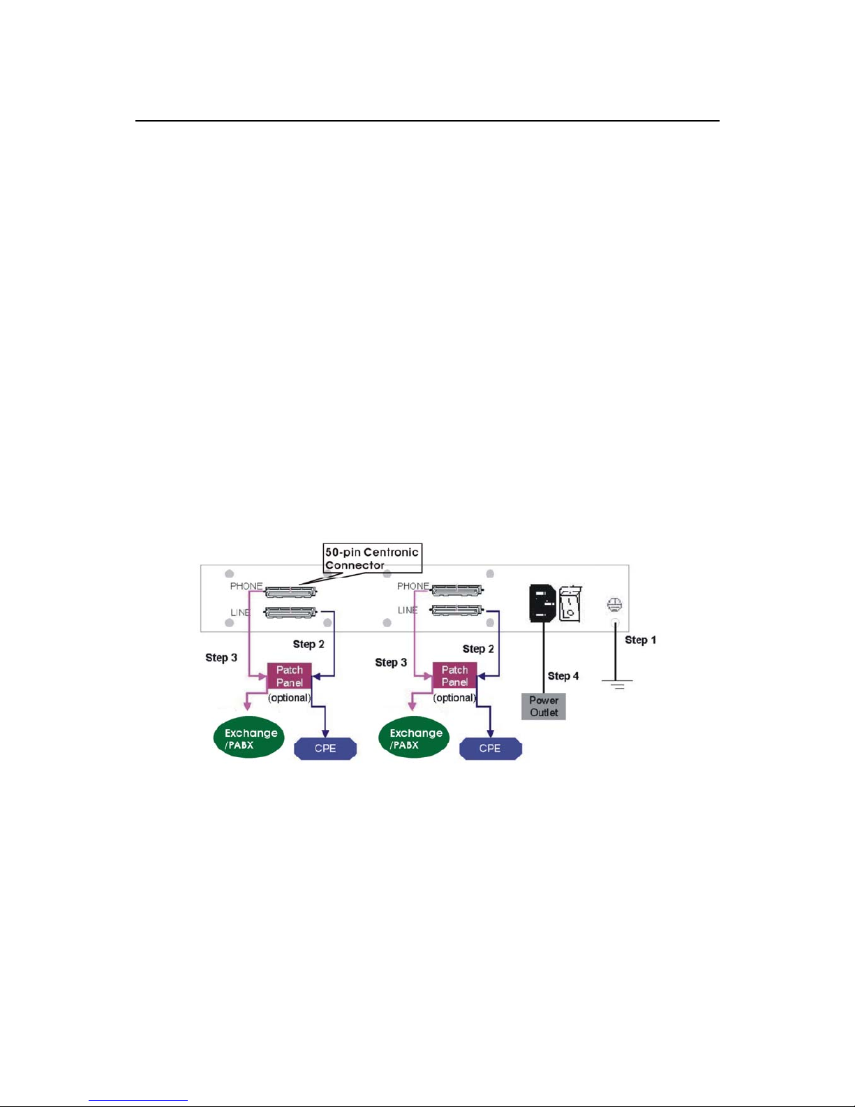
ADSL IP DSLAM Rear Panel Connection
The following figure shows the rear panel connection of ADSL IP DSLAM:
Figure 2-1 ADSL IP DSLAM Rear Panel Connection
Step 1: Ground the ADSL IP DSLAM by connecting a grounded wire
Step 2: Connect the ADSL line connector, a 50-pin centronic connector, of
ADSL IP DSLAM to CPE by using telco cable. Each line connector supports 8
ports of ADSL for Data path from MDF(Main Distribution Frame).
Step 3: Connect the phone connector, a 50-pin centronic connector, of ADSL
IP DSLAM to Exchange/PBX by using telco cable. phone connector is an
optional module supporting Voice path to Exchange/PBX; it must be along with
Line Connector.
Step 4: Connect the power adapter and plug it into an outlet.
Page 24
ADSL IP DSLAM
16
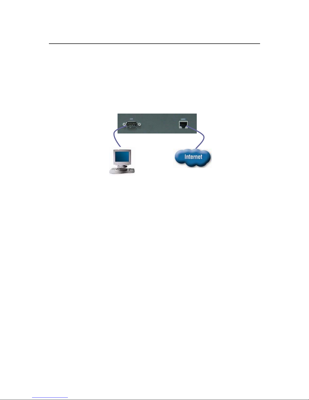
ADSL IP DSLAM Front Panel Connection
Connect the uplink port of ADSL IP DSLAM to internet by using the RJ-45
cable, and Connect the CID port to the console terminal by using the RS-232
cable(Null modem cable) in order to Administer your ADSL IP DSLAM
through CLI.
Figure 2-2 ADSL IP DSLAM Front Panel Connections
Note: Please refer to Appendix A: pin assignment of telco cable, RJ-45 and
RS-232 cable.
UplinkConsole
Console Terminal
For Manufacture
Maintenance Only
Page 25

ADSL IP DSLAM
17
2.4 Ways of Management Connection
This section will tell you how to connect and manage your ADSL IP DSLAM
through EmWeb, CLI and EMS.
Embedded Web Interface(EmWeb)
The embedded Web Interface (EmWeb), comprised of HTML files, is more
user- friendly than CLI for your configuring ADSL IP DSLAM. The HTML files
embedded in ADSL IP DSLAM are dynamically linked to the system’s
functional command sets. You can access the EmWeb from any Web Browser.
Following the following procedure to connect the embedded Web management
interface:
1. Establish a connection to the internet
2. Open the Web browser
3. Enter the IP address of the ADSL IP DSLAM (Default IP:
192.168.100.111)
4. Log in as usual. (User account: Admin; Password: Admin)
To access any menu item on EmWeb, simply click on the item you want. The
corresponding work screen will then appear on the right side frame. By
pressing the Apply button will allow you to achieve your configuration,
whereas pressing Cancel button will clear all your changes without applying
them. In some menus, there will be Modify item will allow you to modify the
existing configuration.
Command Line Interface (CLI)
The Command Line Interface is the most primary character based
configuration interface. Some of configurations not provided in EmWeb can be
configured through CLI. You can access CLI from the terminal emulation
software.
The procedure of connecting to the CLI is as follows:
1. Start up the terminal emulation software on the management station.
If necessary, reconfigure the terminal-emulation software to match the
Page 26

ADSL IP DSLAM
18
switch console port settings.
Bits per second 9600
Data b its 8
Parity None
Stop bits 1
Flow control None
2. Enter Admin when prompted for a user name and password. The ADSL IP
DSLAM prompt appears when you have logged in to the management
interface successfully.
Telnet Client
ADSL IP DSLAM supports only one Telnet client that you can use to connect
with. Telnet provides a simple terminal emulation that allows you to see and
interact with the CLI of ADSL IP DSLAM. As with any remote connection, the
network interface IP address for the ADSL IP DSLAM must be established.
Note: as to the default setting of ADSL IP DSLAM, please refer to the
Appendix-C.
Page 27
ADSL IP DSLAM
19
3. System Administration with EmWeb
3
This chapter provides all the instruction and procedure necessary for you to
administer your ADSL IP DSLAM with EmWeb interface.
3.1 Log In with Embedded Web Interface
This section describes how to log into Embedded Web Interface.
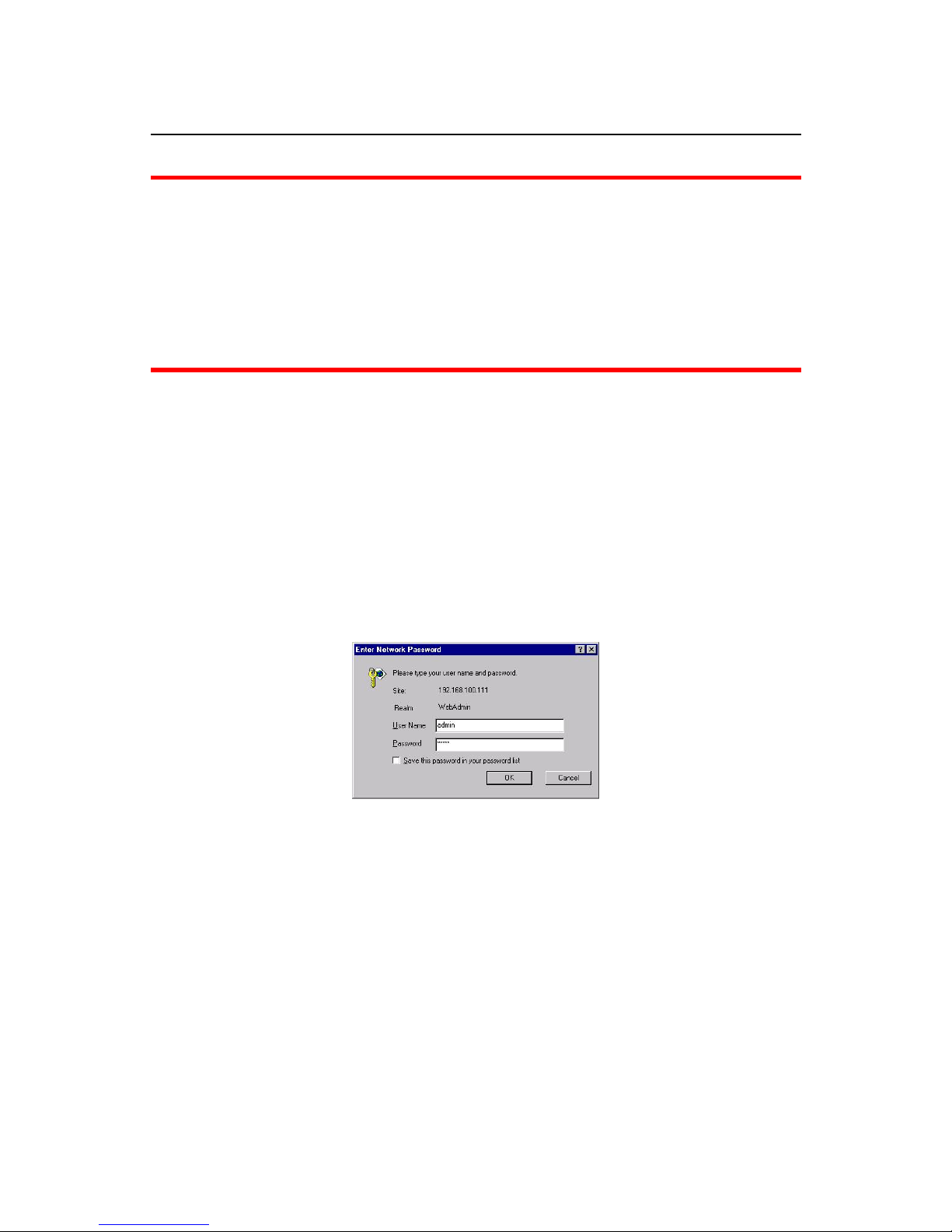
Open a web browser with the default IP address: http://192.168.100.111
The log in screen appears as follows:
1. Enter your user name. If it is an initial installation, enter Admin for user
name.
2. Enter your password. If it is an initial installation, enter Admin for
password.
Note: For safety concern, it is recommended to change the password. For
changing the password, go to the Changing Password in the System
menu. See page 30.
Page 28
ADSL IP DSLAM
20
3.2 Embedded Web Interface Menu
This section describes the overview of the embedded Web interface menu,
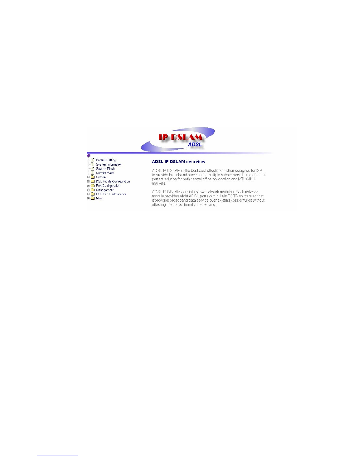
EmWeb. After your successfully logging into the EmWeb, the screen will
appears as follows:
Default Setting
Display the information of default (factory) setting of your ADSL IP DSLAM.
See page 23.
System Information
Display the system time, system up time, system up period of your ADSL IP
DSLAM. It also provides you with the information of software version,
hardware version. See page 24.
Save to Flash
Allow you to save your configuration in Flash. See page 25.
Current Event
Allow you to view the alarm and event status of your ADSL IP DSLAM. See
page 26.
System
Set Port Filter: Allow you configure the port filtering function. See page
28.
System IP / Location: Allow you to configure the IP address and location
of your ADSL IP DSLAM. See page 29.
System Date and Time: Allow you to configure the SNTP status, Time
zone, date and time of your ADSL IP DSLAM. See page 30.
Page 29

ADSL IP DSLAM
21
Changing Password: Allow you to change your password. See page 30.
DSL Profile Configuration
Create Line Profile: Allow you to create ADSL line profile. See page 31.
Create Alarm Profile: Allow you to create ADSL alarm profile. See page
31.
Current Line Profile: Allow you to view, modify, or delete existing ADSL
line profiles. See page 33.
Current Alarm Profile: Allow you to view, modify, or delete existing ADSL
alarm profiles. See page 34.
Port Configuration
DSL Port configuration: Allow you to display, modify and delete the
status of the port. It provides the configuration of a port’s status. See page
35.
PVC Configuration: Allow you to configure PVC and VID on a port and
set the priority. It also provides the modification and delete function. See
page 36.
List of Subscriber: Allow you to view the existing information of
subscribers and modify them. See page 38.
Routing Table: allow you to configure the routing table. See page 39.
Management
SNMP: Allow you to configure SNMP access parameters and trap IPs. See
page 41.
Management IP: Allow you to configure the management IPs so that only
with those configured management IPs can access to your ADSL IP
DSLAM remotely. See page 41.
DSL Port Performance
Physical Layer Info: Allow you to view the performance information on
physical layer by specifying the definite unit. See page 42.
Channel Layer Info: Allow you to view the performance information on
channel layer by specifying the definite unit. See page 43.
Current Phy-Layer PM: Allow you to view the physical layer performance
collected within current 15 minutes and a day duration. See page 44.
Current Channel-Layer PM: Allow you to view the channel layer
Page 30

ADSL IP DSLAM
22
performance collected within current 15 minutes and a day duration. See
page 46.
15 MIN Phy-Layer PM: Allow you to view the physical layer performance
during previous 15 minutes interval. See page 47.
1 DAY Phy-Layer PM: Allow you to view the physical layer performance
during previous 1 day interval. See page 48.
15 MIN Channel-Layer PM: Allow you to view the channel layer
performance during previous 15 minutes interval. See page 49.
1 DAY Channel-Layer PM: Allow you to view the channel layer
performance during previous 1 day interval. See page 50.
Miscellanea
IGMP Snooping Config: Allow you to configure the IGMP Snooping. See
page 51.
IGMP Snooping Status: allow you to view IGMP snooping status. See
page 51.
Page 31

ADSL IP DSLAM
23
3.3 Default (Factory) Configuration Settings {Default
Setting}
This section describes how to get the information of the default setting of your
ADSL IP DSLAM.
1. Click on “Default Setting” from the ADSL IP DSLAM Main Menu.
The Default Setting screen appears as follows:
Default Settings
SNMP:
community : “public”
no In-band management channel
IP
IP : 192.168.100.111
Mask: 255.255.255.0
Gateway: 192.168.100.1
System
Bridge – mode
Port-Filter(Port-based VLAN) : Enable
ADSL Port
“up” for all ports
VCC
connection
8/81(vpi/vci) for all ports
VLAN – tag : disable
DSL profile
named “DEFAULT”
1) tx mode : “adaptAtStartup”
2) Line type : “Interleaved”
3) Target SNR margin : “6 dB”
4) mim tx rate : “32 Kbps”
5) max tx rate at ATU-C : “8064 Kbps”
6) max tx rate at ATU-R : “1024 Kbps”.
7) interleave delay : “16 milliseconds”
Alarm
profile
named “DEFAULT”
ATU-C side:
Thresh15MinLofs – 0 sec
Thresh15MinLoss – 0 sec
Thresh15MinLols – 0 sec
Thresh15MinLprs – 0 sec
Thresh15MinEss – 0 sec
initial failure trap – Enable
ATU-R side :
Thresh15MinLofs – 0 sec
Thresh15MinLoss – 0 sec
Thresh15MinLols – 0 sec
Thresh15MinLprs – 0 sec
In the default setting table, the status of SNMP, IP, System, ADSL Port, VCC
connection, DSL profile and Alarm profile are displayed clearly. How to modify
them will be introduced in the following sections.
Page 32
ADSL IP DSLAM
24
3.4 Displaying the System Information of your ADSL IP
DSLAM {System Information}
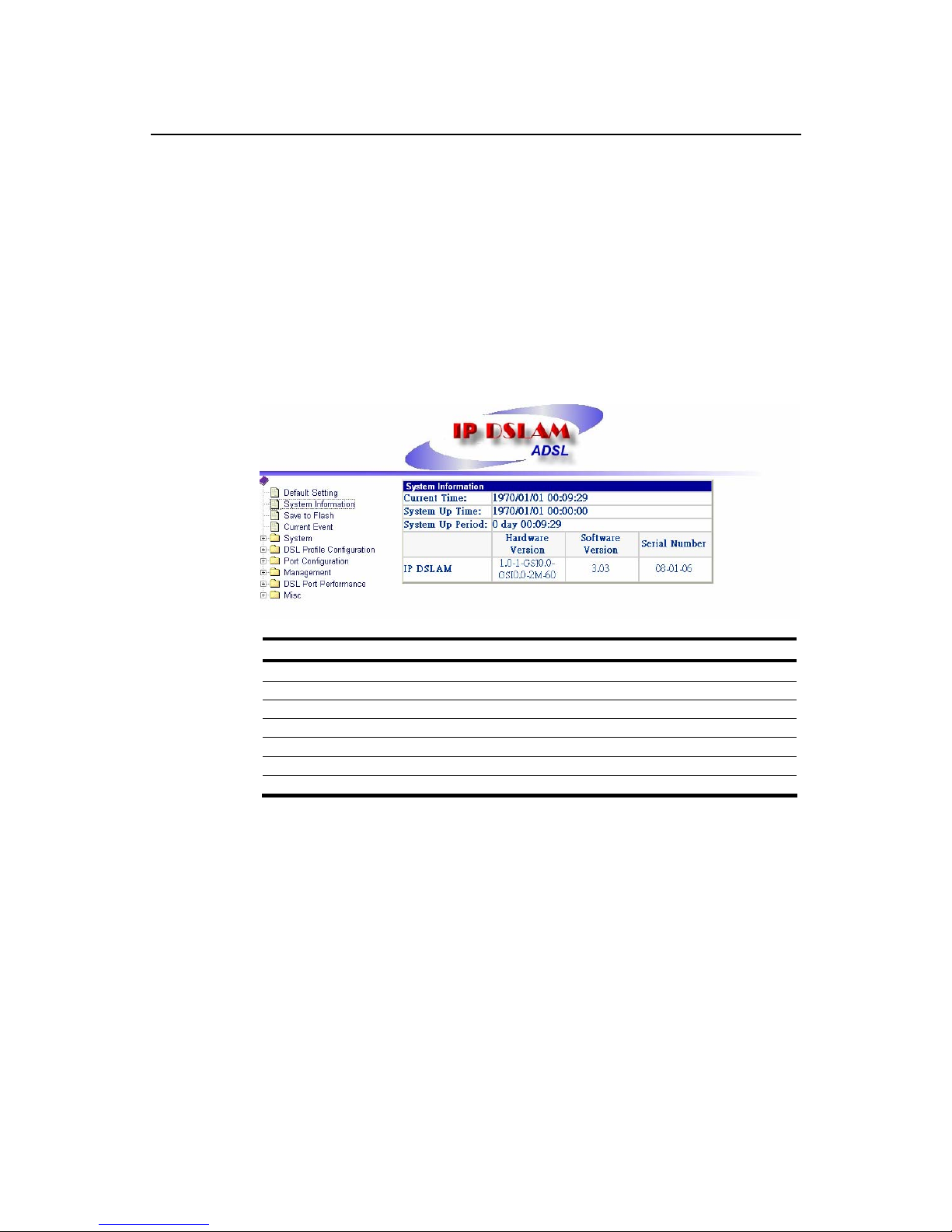
This section describes how to get the information of your ADSL IP DSLAM.
1. Click on “System Information” from the ADSL IP DSLAM Main Menu.
The System Information screen appears as follows:
Table 3-1 Sysinfo field definition
Field Definition
Current time Current system time
System Up time System up time
System Up Period System Up Period
Model name Model name of the system.
Hardware version Hardware version of system.
Software version Software version of system.
MAC Address MAC Address of system
Page 33
ADSL IP DSLAM
25
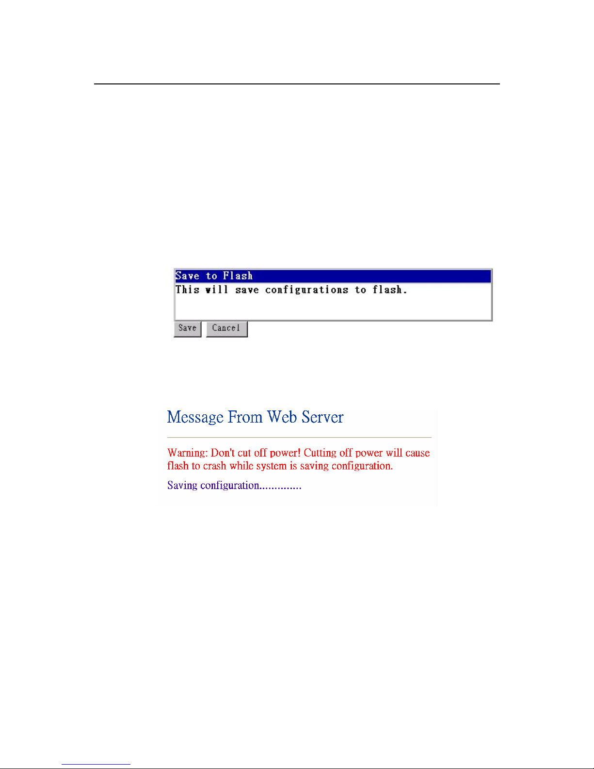
3.5 Save your Configuration to Flash {Save to Flash}
This section describes how to save the configuration you have configured to
flash. This function will be needed whenever you want to restart your ADSL IP
DSLAM with the updated configuration.
1. Click on “Save to Flash” from the ADSL IP DSLAM Main Menu.
The Save to Flash screen appears as follows:
2. Submit the Save button.
3. After submitting the Save bottom, a warning message from Web Server will
pop-up immediately as the following screen shown.
Note: don’t cut off power while system is saving your configuration.
Page 34
ADSL IP DSLAM
26
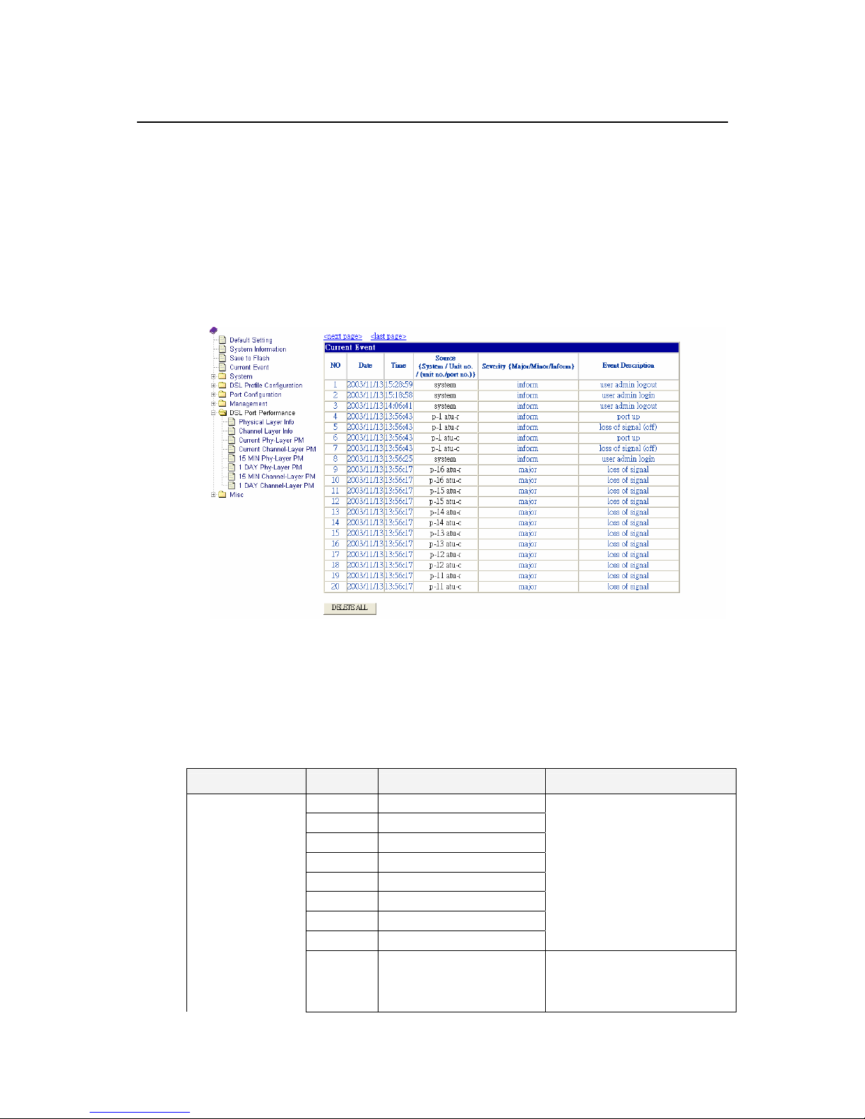
3.6 Displaying Current Event {Current Event}
This section describes how to view the current alarm and event status.
1. Click on “Current Event” from the ADSL IP DSLAM Main Menu. The
Current Event screen appears as follows:
2. Click on next page item in order to view more events. The displayed data
will be 20 items per page and it can display totally up to 960 items.
3. Click on DELETE ALL button in order to delete all events. The following
event log description would help you to know the content of event logs in the
Current Event screen.
Table 3-2 Event log description
Module Severity Description Note
Inform port up
Major port down
Inform transmit rate has changed
Major loss of framing
Major loss of signal
Major loss of power
Minor loss of signal quality
Major loss of link
ADSL related
Major data init. failure
ATU-C failure during
initialization due to bit errors
corrupting startup exchange
data.
Page 35

ADSL IP DSLAM
27
Major configuration init. failure
ATU-C failure during
initialization due to peer ATU
not able to support requested
configuration
Major protocol init. failure
Incompatible protocol used by
the peer ATU
Major no peer ATU present
No activation sequence
detected from paired endpoint.
Minor los
Minor lof
Minor lpr Threshold violation
Minor es
Minor lol
Inform system up
Inform user "xxx" login
Inform user "xxx" logout
Inform no defect
Major hardware failure
Inform up-link connected
System related
Inform up-link disconnected
Inform unit plugged
Inform unit unplugged
Inform no defect
Unit related
Major hardware failure
Inform port Admin. Enabled
Admin related
Major port Admin. disabled
Page 36
ADSL IP DSLAM
28
3.7 Configuring ADSL IP DSLAM
This section describes how to configure your ADSL IP DSLAM by selecting
System from EmWeb Menu. This section will cover all the function from
System Menu. It includes:
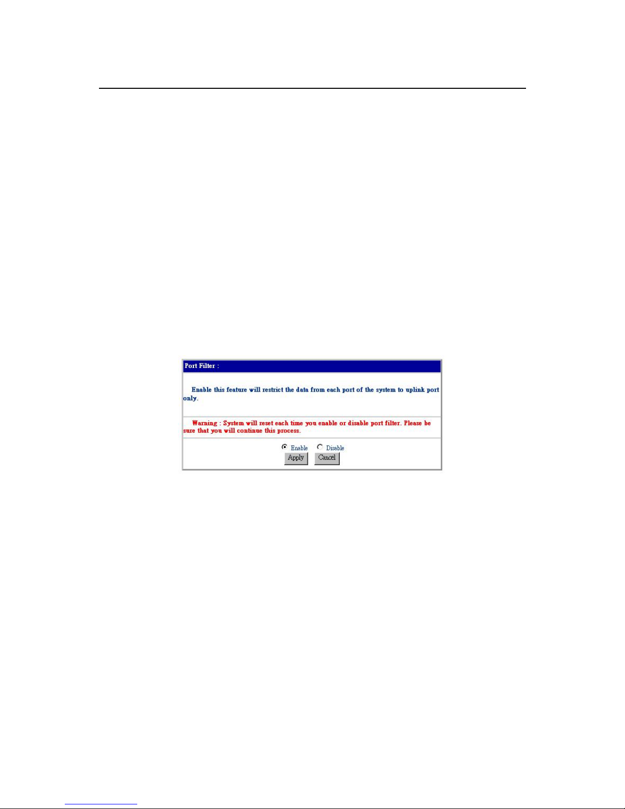
Configuring Port Filtering {Set Port Filter}
Allow you to configure the port filtering function.
1. Click on “Set Port Filter” from the System Menu.
The Set Port Filter screen appears as follows:
2. Click on Enabled button to allow each ADSL port to communicate back and
forth with the uplink Ethernet port only.
By selecting Disabled button you allow all ADSL ports to communicate with
each other and also with the uplink Ethernet port.
3. Press Apply button in order to submit your configuration.
Note: Make sure to save all the configurations in flash by selecting Save to
Flash from main menu when you want to restart your ADSL IP DSLAM.
Page 37
ADSL IP DSLAM
29
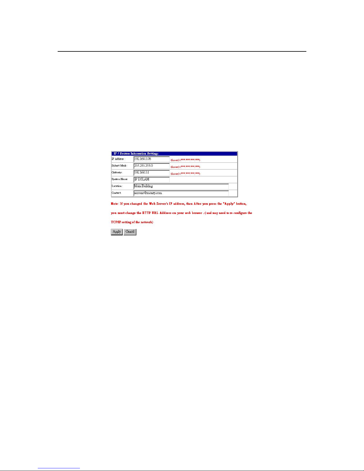
Configuring IP and Location {System IP / Location}
Allow you to configure the system IP address and location.
1. Click on “System IP / Location” from the System Menu.
The System IP / Location screen appears with the default setting and can be
configured as follows:
2. Configure the IP address you want to set, say 192.168.0.76
3. Configure the subnet mask with reference to IP address, say 255.255.255.0
4. Configure the gateway with reference to IP address, say 192.168.0.1
5. Configure the system name you want to set, say ADSL IP DSLAM
6. Configure the location of your ADSL IP DSLAM.
7. Configure the contact information for servicing ADSL IP DSLAM.
8. Click on the Apply button to submit your changes, or click on the Cancel
button if you want to clear all the values you have configured.
Note: If you changed the Web Server's IP address, you must change the HTTP
URL Address on your web browser, after your pressing the "Apply" button,
(The TCP/IP setting of the network may need to re-configure).
Page 38
ADSL IP DSLAM
30
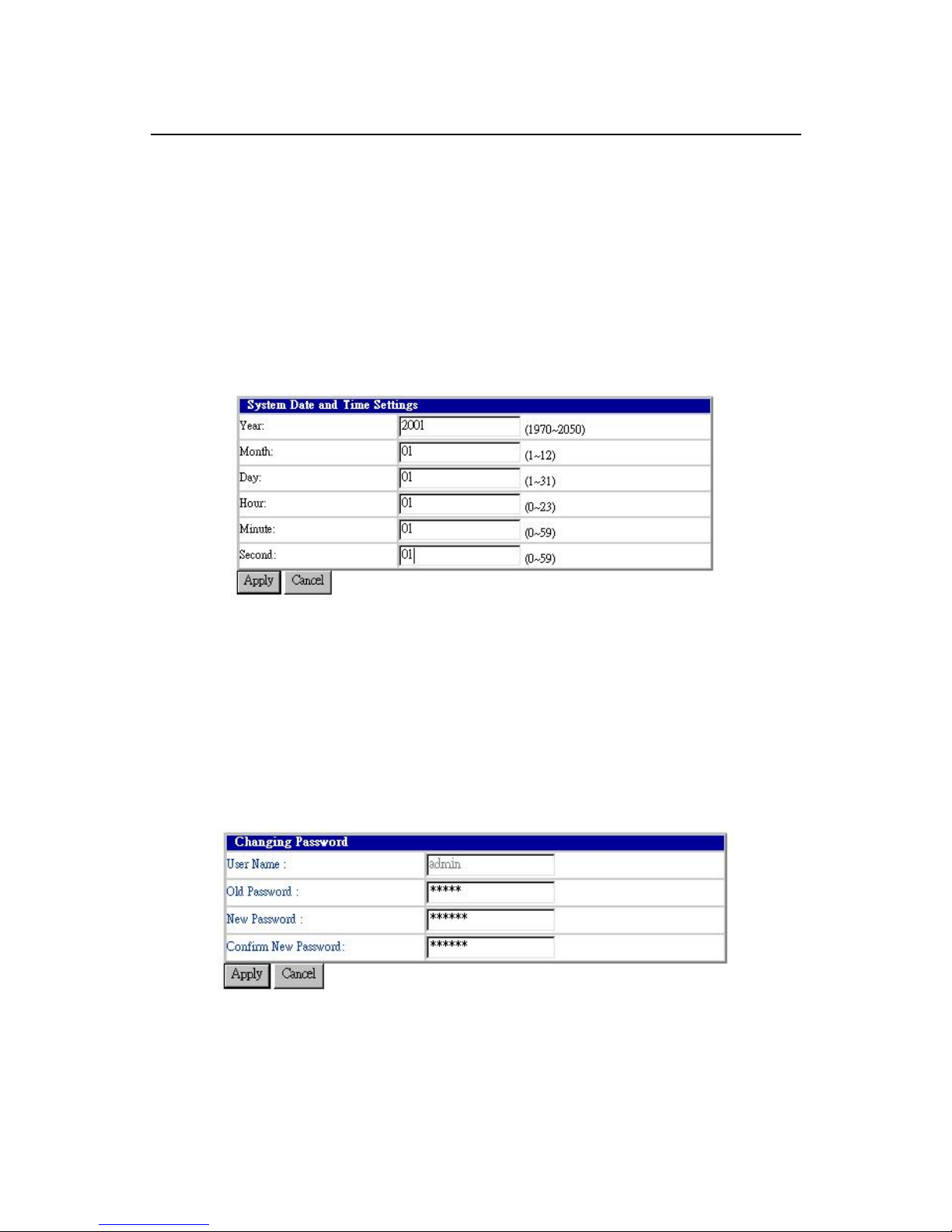
Configuring Date and Time {System Date and Time}
Allow you to configure the date and time of the system.
1. Click on “System Date and Time” from the System Menu.
The System Date and Time screen appears with the default setting and can
be configured as follows:
Changing your Password {Changing Password}
Allow you to change your password.
1. Click on “Changing Password” from the System Menu.
The Changing Password screen appears with your user name and your
password can be changed as follows:
2. Enter your old password.
3. Enter your new password that you want to change.
4. Enter your new password again to confirm.
5. Click on the Apply button to submit your changes, or click on the Cancel
button if you want to clear all the values you have configured.
Page 39
ADSL IP DSLAM
31
3.8 DSL Line Configuration
This section covers how to create, display, modify, or delete the line profile
and alarm profile by selecting DSL Line Configuration from EmWeb Menu.
This section will cover all the function from DSL Line Configuration Menu.
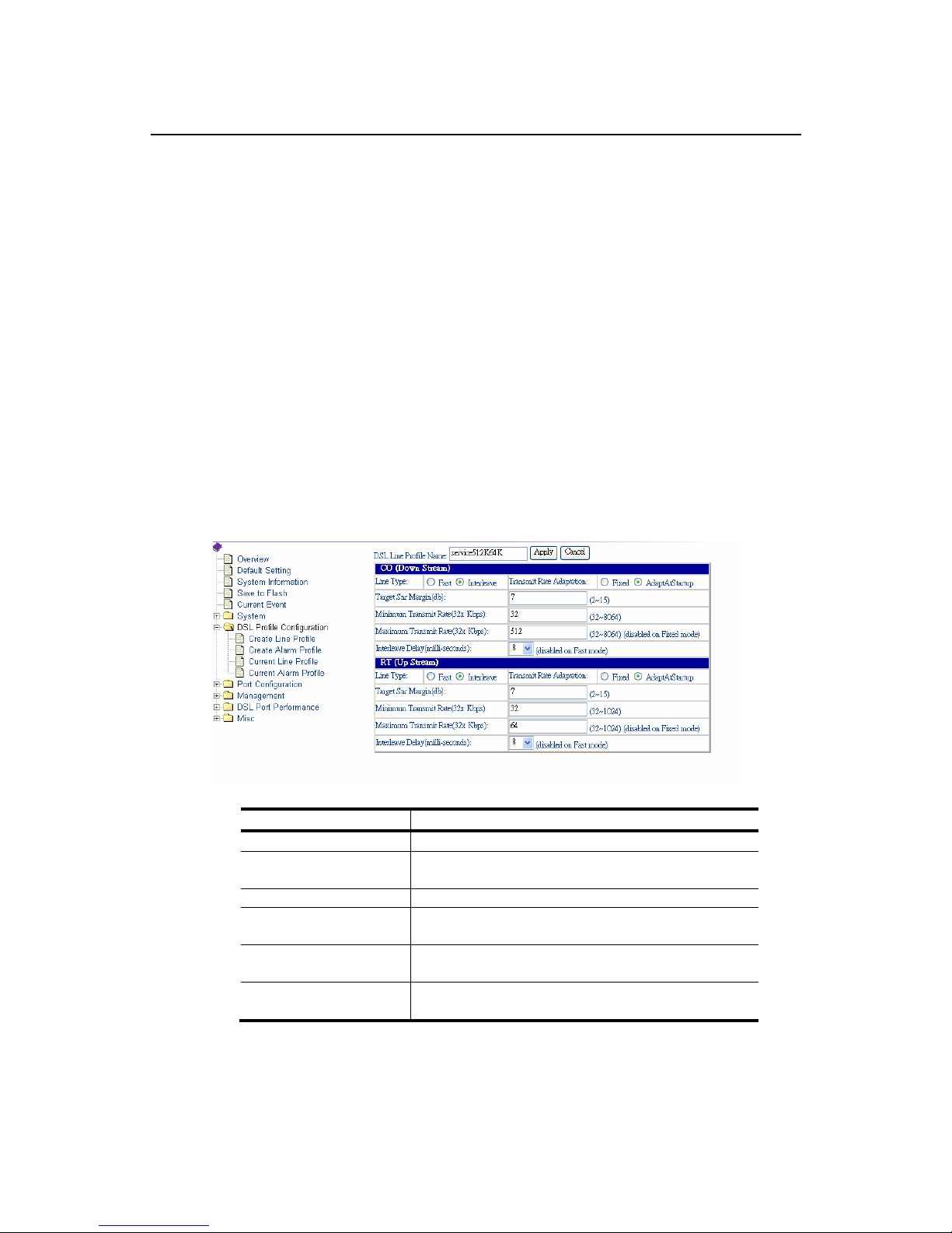
Creating a Line Profile {Create Line Profile}
This section describes how to create an ADSL line profile.
1. Click on “Create Line Profile” of DSL Profile configuration Menu.
The Create Line Profile screen appears as follows:
Table 3-3 Create Line Profile Field Definitions
2. Configure the name of line profile, say service512K64K.
3. Configure the line profile on CO side (Down Stream). For example,
4. Configure the line type, transmit rate adaptation, target SNR margin,
minimum transmit rate, maximum transmit rate, and interleave delay as
Field Definition
Line Type The ADSL line type, Fast or Interleaved
Transmit Rate
Adaption
Defines what form of transmitting rate to be
adaptated, fixed or adaptAtStartup
Target Snr Margin (db) Target Signal / Noise Margin.
Minimum Transmit
Rate
The minimum transmitting rate of ATU-C side or
ATU-R side.
Maximum Transmit
Rate
The maximum transmitting rate of ATU-C side or
ATU-R side.
Interleave Delay
(mili-seconds)
The value of Interleave Delay for this channel.
Page 40
ADSL IP DSLAM
32
Interleaved, AdaptAtStartup, 7 db, 32 Kbps, 512 Kbps, and 8 milli-seconds.
5. Configure the line profile on RT side (Up Stream). For example,
6. Configure the line type, transmit rate adaptation, target SNR margin,
minimum transmit rate, maximum transmit rate, and interleave delay as
Interleaved, AdaptAtStartup, 7 db, 32 Kbps, 64 Kbps, and 8 milliseconds.
7. Click on the Apply button to submit your changes, or click on the Cancel
button if you want to clear all the values you have configured.
Note: (1) If you configure “Transmit Rate Adaptation” as “Fixed”, it is
recommended to configure the value of “minimum transmit rate” and
“maximum transmit rate” on CO side or RT side the same. However,
the value of CO side and RT side may not be the same.
(2) Line profile can be created maximum up to 10 profiles.
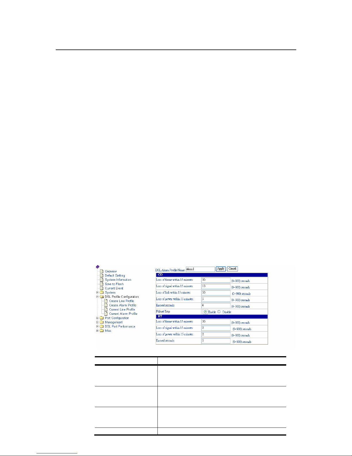
Creating a Alarm Profile {Create Alarm Profile}
This section describes how to create an ADSL alarm profile.
1. Click on “Create Alarm Profile” of DSL Profile configuration Menu.
The Create Alarm Profile screen appears as follows:
Table 3-4 Create Alarm Profile Field Definitions
Field Definition
Loss of frame within 15
minutes
The threshold of the number of “Loss of Frame
Seconds” within 15 minutes performance data
collection period.
Loss of signal within 15
minutes
The threshold of the number of “Loss of Signal
Seconds” within 15 minutes performance data
collection period.
Loss of link within 15
minutes
The threshold of the number of “Loss of Link
Seconds” within 15 minutes performance data
collection period. (But only ATU-C side)
Loss of power within The threshold of the number of “Loss of Power
Page 41
ADSL IP DSLAM
33
15 minutes Seconds” within 15 minutes performance data
collection period.
Errored seconds The threshold of the number of “Errored
Seconds” within 15 minutes performance data
collection period.
Failure Trap Enable or disable the Initial Failure Trap. Default
setting is disable. (Only on ATU-C side)
2. Configure the name of alarm profile, say alarm1.
3. Configure the alarm profile on CO side (Down Stream). For example,
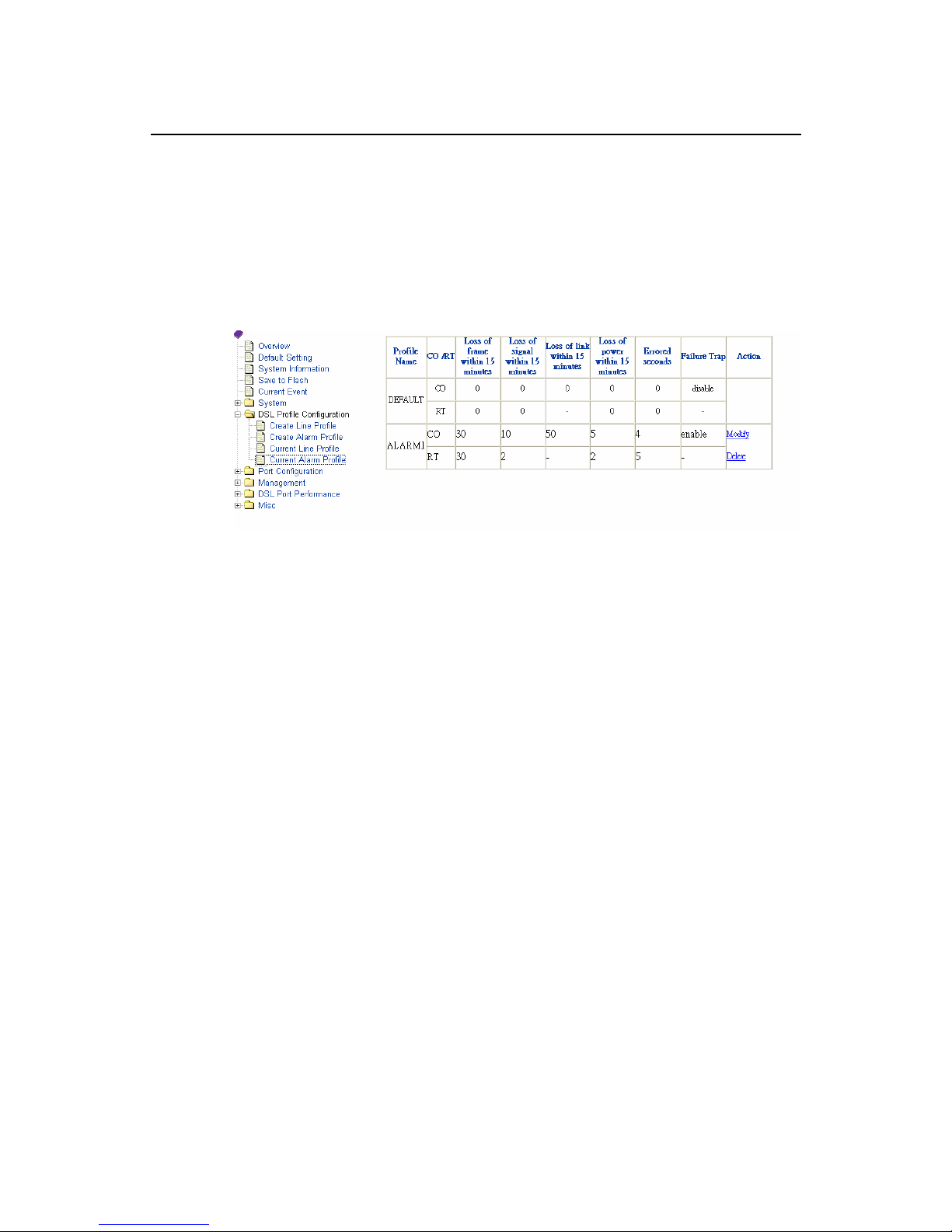
4. Configure the Lofs, Loss, Lols, Lprs, Ess, and initial failure trap as 30sec,
10sec, 50sec, 5sec, 4sec, and Enable initial failure trap.
5. Configure the alarm profile on RT side (Up Stream). For example, Configure
the Lofs, Loss, Lprs, and Ess as 30sec, 2sec, 2sec, and 5sec.
6. Click on the Apply button to submit your changes, or click on the Cancel
button if you want to clear all the values you have configured.
Note: The alarm profile can be created maximum up to 10 profiles.
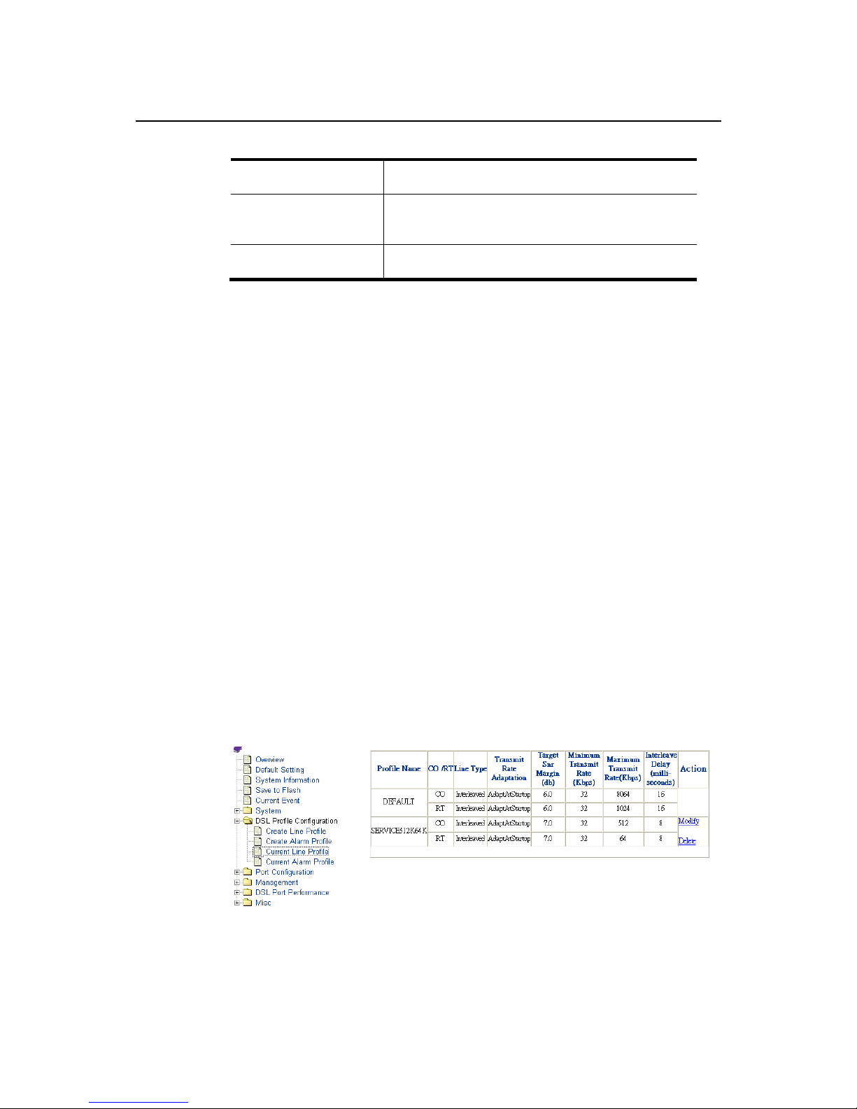
Displaying and Modifying a Line Profile {Current Line Profile}
Allow you to view, modify, or delete existing ADSL line profiles.
1. Click on “Current Line Profile” of the DSL Profile configuration Menu.
The Current Line Profile screen appears as follows:
2. Click on Modify button to modify the specified profile.
3. Click on Delete button to delete the specified profile.
Page 42
ADSL IP DSLAM
34
Displaying and Modifying a Alarm Profile {Current Alarm Profile}
Allow you to view, modify, or delete existing ADSL alarm profiles.
1. Click on “Current Alarm Profile” of the DSL Profile configuration Menu.
The Current Alarm Profile screen appears as follows:
2. Click on Modify button to modify the specified profile.
3. Click on Delete button to delete the specified profile.
Page 43
ADSL IP DSLAM
35
3.9 Port Configuration
This section covers how to configure ports and subscriber information by
selecting Port Configuration from EmWeb Menu. This chapter will cover all
the function from Port Configuration Menu.
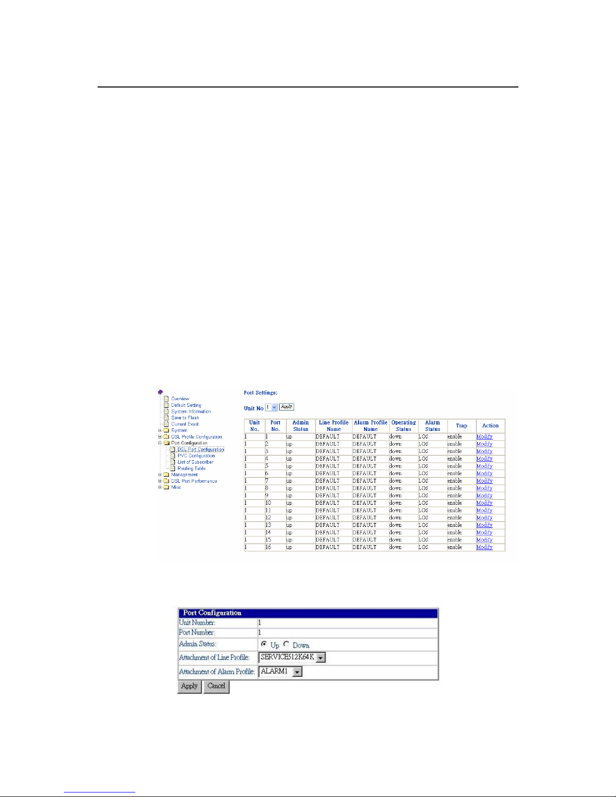
DSL Port Configuration{DSL Port Configuration}
Allow you to display, modify and delete the status of the port. It also provides
the configuration of enabling or disabling a port and attaching the specific line
profile and alarm profile to a port. The procedures are as follows:
1. Click on “DSL Port Configuration” of the Port configuration Menu.
For first time configuration, the DSL Port Configuration screen appears with
the default setting as follows:
2. Click on Modify button to configure the specific port, says port 1. The screen
will appear as follows:
3. Configure the Administration status as “Up” or “Down”. Here in example,
“Up” is configured.
4. Attach the line profile, says “SERVICE512K64K”
Page 44
ADSL IP DSLAM
36
5. Attach the alarm profile, says “ALARM1”
6. Click on the Apply button to submit your changes, or click on the Cancel
button if you want to clear all the values you have configured.
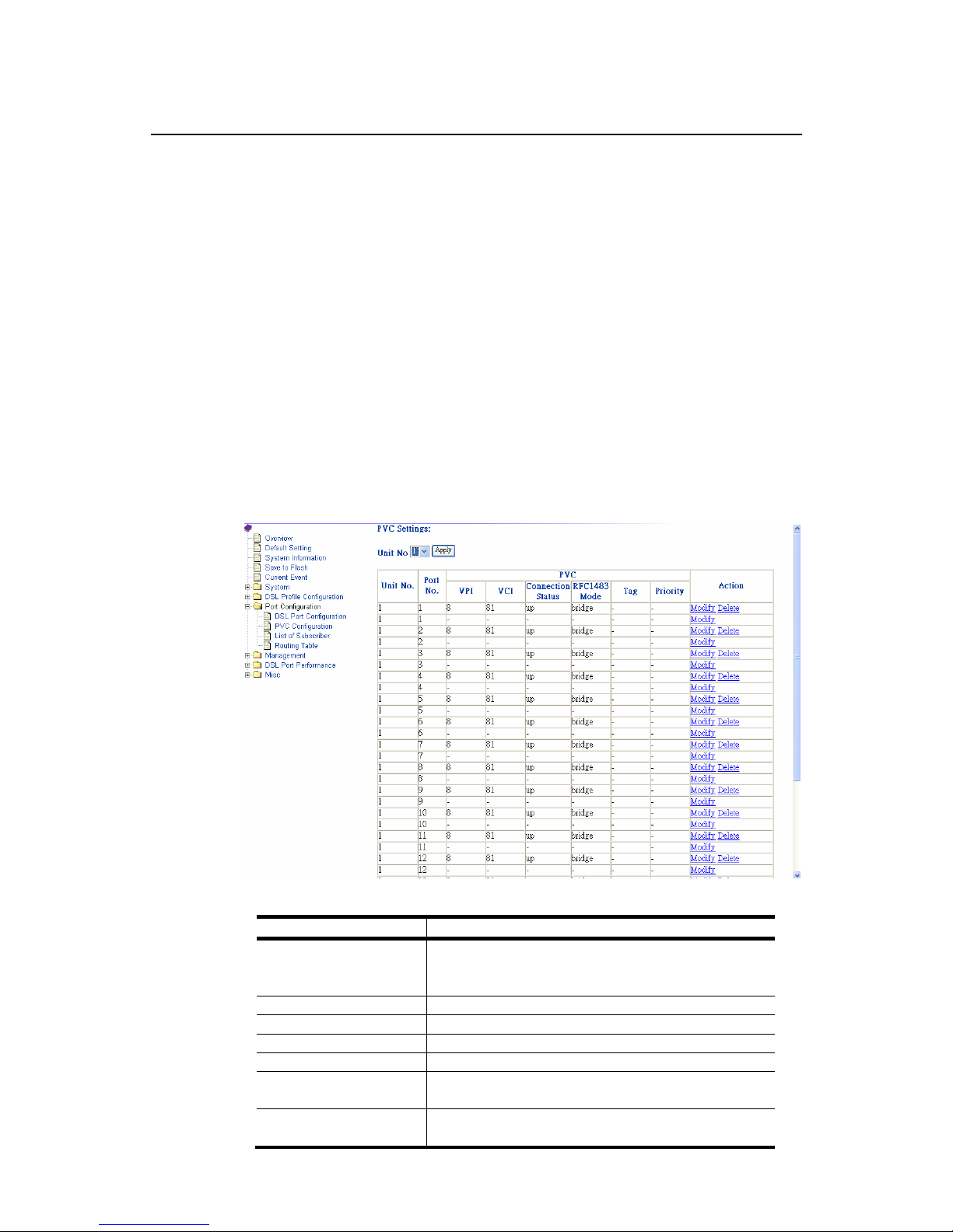
PVC Configuration{PVC Configuration}
Allow you to configure PVC (Permanent Virtual Connection) and VID (VLAN ID)
on a port and setting the priority. It also provides the modification and delete
function. The procedures are as follows:
1. Click on “PVC Configuration” of the Port configuration Menu.
For the first time configuration, the PVC Configuration screen appears with
the default setting as follows:
Table 3-5 PVC Configuration Field Definitions
Field Definition
Port No. The threshold of the number of “Loss of Signal
Seconds” within 15 minutes performance data
collection period.
VPI Virtual Path Identifier
VCI Virtual Channel Identifier
Connection Status Used to up/down connection.
RFC1483 Mode Bridge or route
Tag Specifies the port as either 802.1Q tagging or
802.1Q untagged.
Priority Optional Connection priority. No VLAN tag, no
priority.
Page 45
ADSL IP DSLAM
37
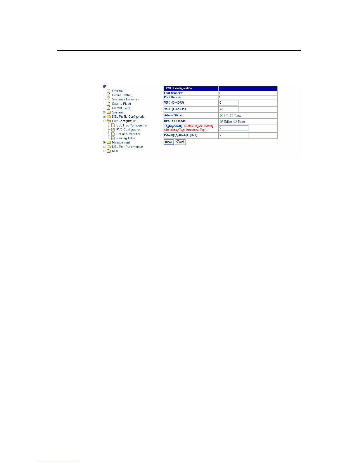
2. Click on Modify button to configure the specific port, says port1. The screen
will appear as follows:
3. Configure the VPI, says 0
4. Configure the VCI, says 50
5. Configure the Administration status of PVC “Up” or “Down”, says “Up.
6. Configure the RFX1483 Mode. Here in example, “Bridge” is configured.
7. Configure the Tag, says 7.
8. Configure the priority of PVC, says 7. The priority of 0 to 7 is from the lowest
to the highest.
9. Click on the Apply button to submit your changes, or click on the Cancel
button. If you want to clear all the values you have configured.
Page 46
ADSL IP DSLAM
38
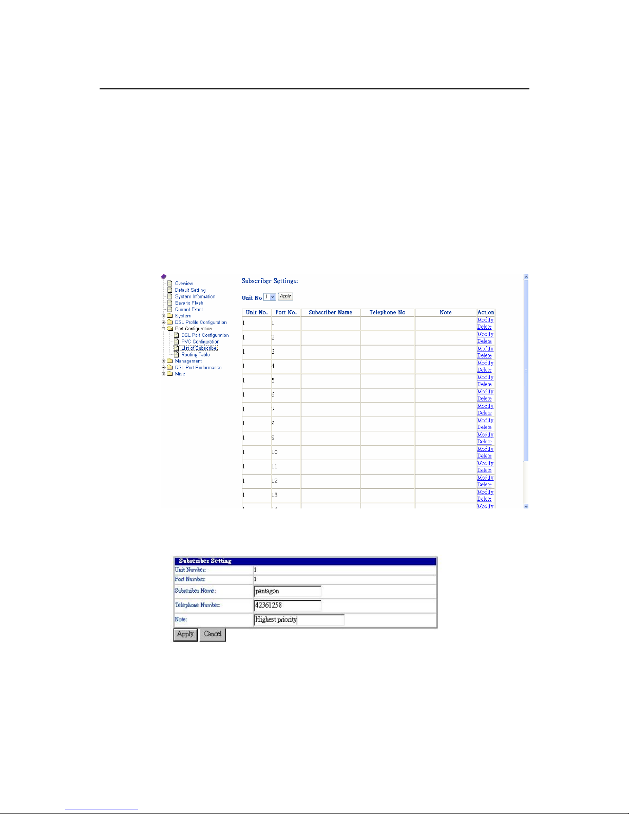
List of Subscriber {List of Subscriber}
Allow you to view the existing information of subscribers and modify them. The
procedures are as follows:
1. Click on “List of Subscriber” of the Port configuration Menu.
For the first time configuration, the List of Subscriber screen appears with the
default setting as follows:
2. Click on Modify button to configure the specific port, says port1. The screen
will appear as follows:
3. Configure the subscriber name as you want, says Pantagon.
4. Configure the telephone number of subscriber, says 42361258
5. Write Note for your reference if you need.
6. Click on the Apply button to submit your changes, or click on the Cancel
button if you want to clear all the values you have configured.
Page 47
ADSL IP DSLAM
39
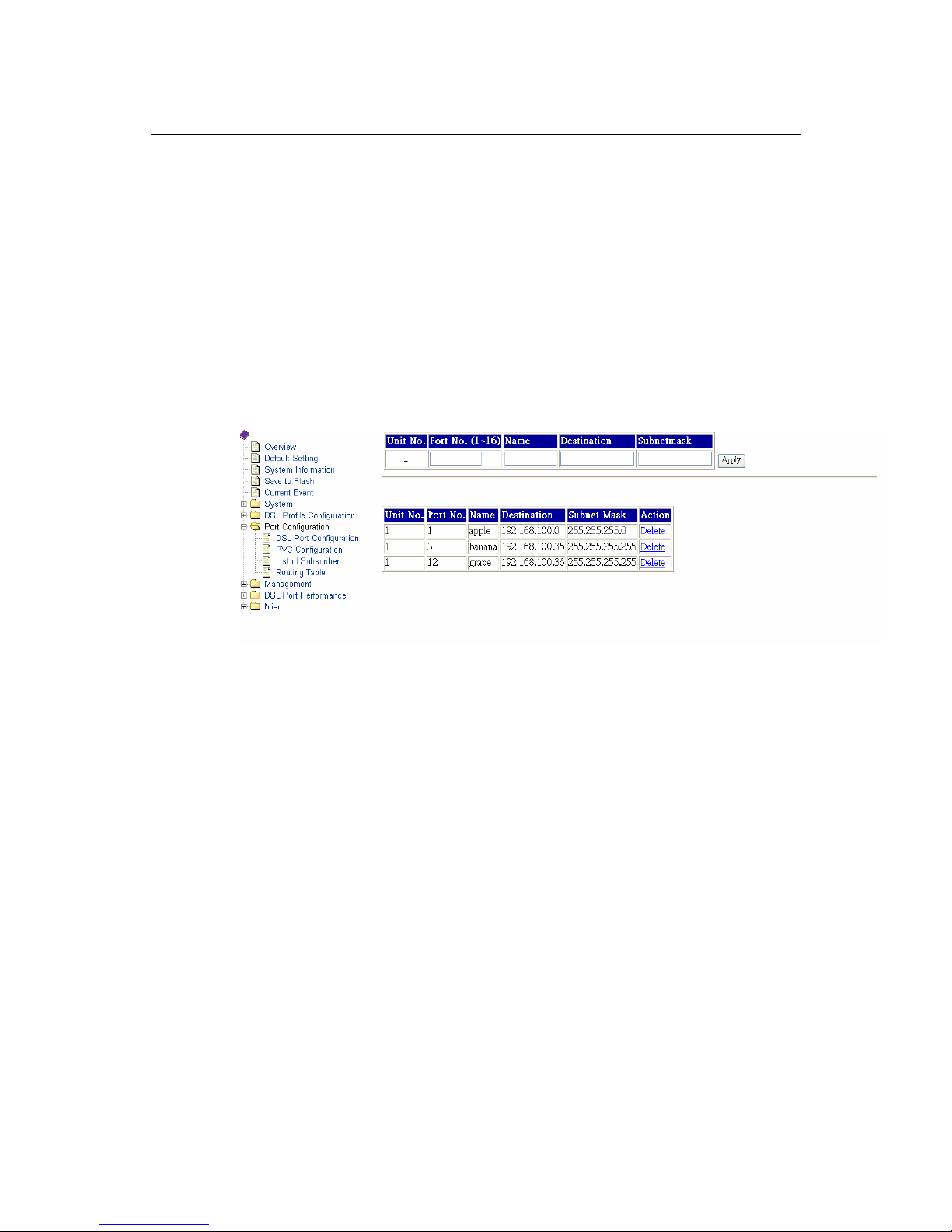
Routing Table {Routing Table}
Routing Table is a matrix with a network control protocol, which gives the
hierarchy of link routing at each node.
The Routing Table screen allows you to view the routing table built in the ADSL
IP DSLAM and modify them. The procedures are as follows:
1. Click on “List of Subscriber” of the Port configuration Menu. The Routing
Table screen appears with the default setting as follows:
2. Configure the Port No. (1~16), Name, Destinations and Subnet mask
separately, and then click on the Apply button.
3. The newly added routing node will be listed in the routing table. If to delete
one routing node, click on the Delete.
Note: only can the routing table be configurable, when the RFC-1483 mode is
configured as “Route”. Please refer to the setting in the PVC
Configuration, page 36.
Page 48
ADSL IP DSLAM
40
3.10 Management Configuration
This section covers how to configure SNMP access parameters and
management IP by selecting Management from EmWeb Menu. This section
will cover all the function from Management Menu. It includes:
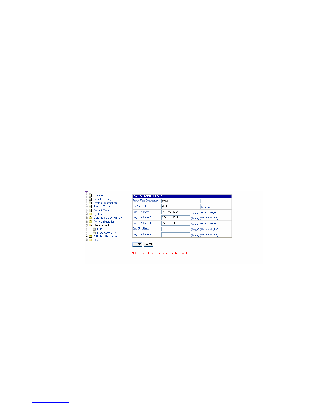
Configuring SNMP Access Parameters and Trap IPs {SNMP}
Allow you to configure the SNMP access parameters and trap IPs. The
procedures are as follows:
1. Click on “SNMP” of the Management Menu.
For the first time configuration, the SNMP screen appears with the default
setting of the community string” public” as follows:
2. Configure the VID (VLAN ID) of the system from 2 to 4094.
3. Configure the trap IP Addresses, as you want. Here in example, we create 3
IPs. The trap IP can be created maximum up to 5.
4. Click on the Apply button to submit your changes, or click on the Cancel
button if you want to clear all the values you have configured.
Page 49
ADSL IP DSLAM
41
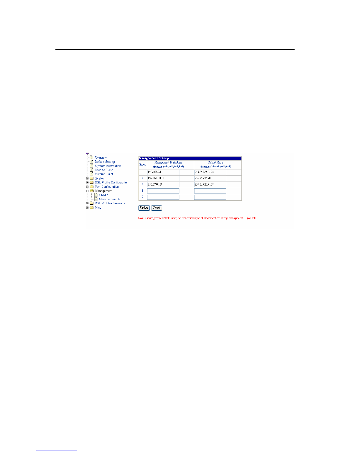
Configuring Management IP {Management IP}
Allow you to configure the management IPs so that only with those configured
management IPs can access to your ADSL IP DSLAM remotely. The
procedures are as follows:
1. Click on “Management IP” of the Management Menu.
The Management IP screen appears as follows:
2. Configure the management group, as you want. The management IP group
can be created maximum up to 5 groups.
3. Click on the Update button to submit your changes, or click on the Cancel
button if you want to clear all the values you have configured.
Page 50
ADSL IP DSLAM
42
3.11 Performance Monitor
This section covers performance monitor by selecting DSL Port
Performance from EmWeb Menu. It includes:
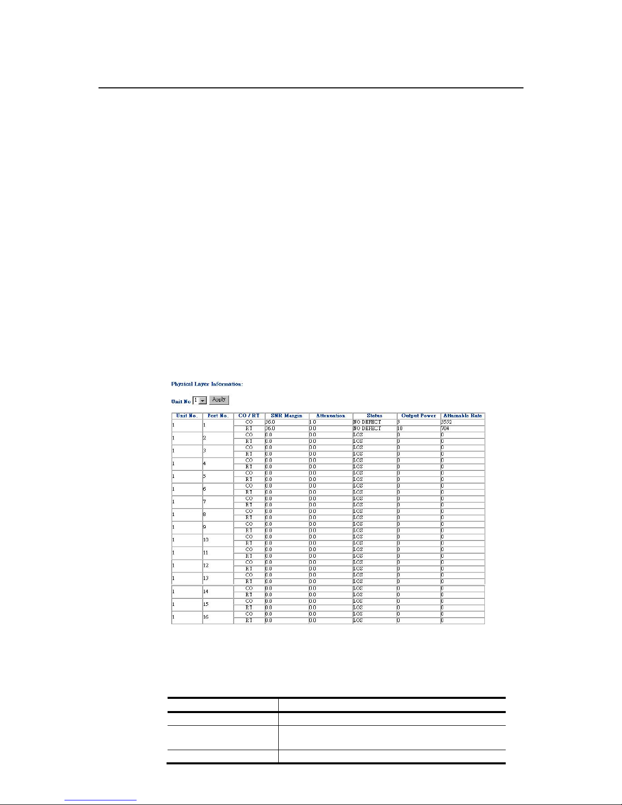
ADSL Physical La yer PM {Physical Layer Info}
Allow you to view the performance information on physical layer by specifying
the definite unit. The procedures are as follows:
1. Click on “Physical Layer Info” of DSL Port Performance Menu.
The Physical Layer Info screen appears as follows:
Note: In this example, only port 1 is connected with CPE and that is why only
“No defect” value is displayed in the unit 1/port 1 row.
Table 3-6 Physical Layer Info Field Definitions
Field Definition
SNR margin Noise margin value. (dB)
Attenuation Difference in the total power transmitted and the
total power received by the peer atu. (db)
Status Current status of the ATU line. The possible
Page 51
ADSL IP DSLAM
43
values displayed are as follows:
No defect: there are no defect on the line
los: atu-r failure due to not receiving signal
lpr: atu-r failure due to loss of signal
output power Total output power transmitted by atu. (dBm)
attainable rate The maximum currently attainable data rate by
the atu. (kbps)
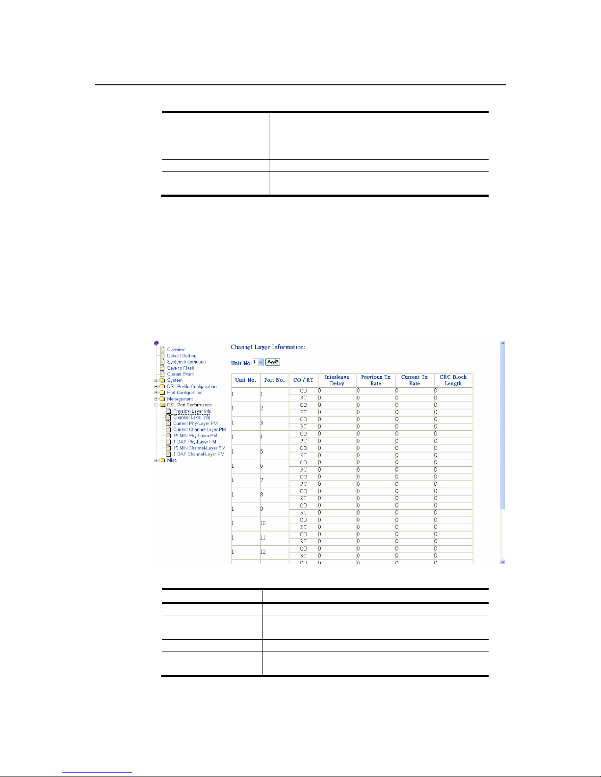
ADSL Channel Layer PM {Channel Layer Info}
Allow you to view the performance information on channel layer by specifying
the definite unit. The procedures are as follows:
1. Click on “Channel Layer Info” of DSL Port Performance Menu.
The Channel Layer Info screen appears as follows:
Table 3-7 Channel Layer Information Field Definitions
Field Definition
Interleave delay Interleave delay for this channel. (milli-seconds)
Previous TX rate previous actual transmit rate on this channel if
ADSL loop retain. (kbps)
Current TX rate Actual transmit rate on this channel. (kbps)
CRC block length The length of the channel data-block on which the
CRC operates.
Page 52
ADSL IP DSLAM
44
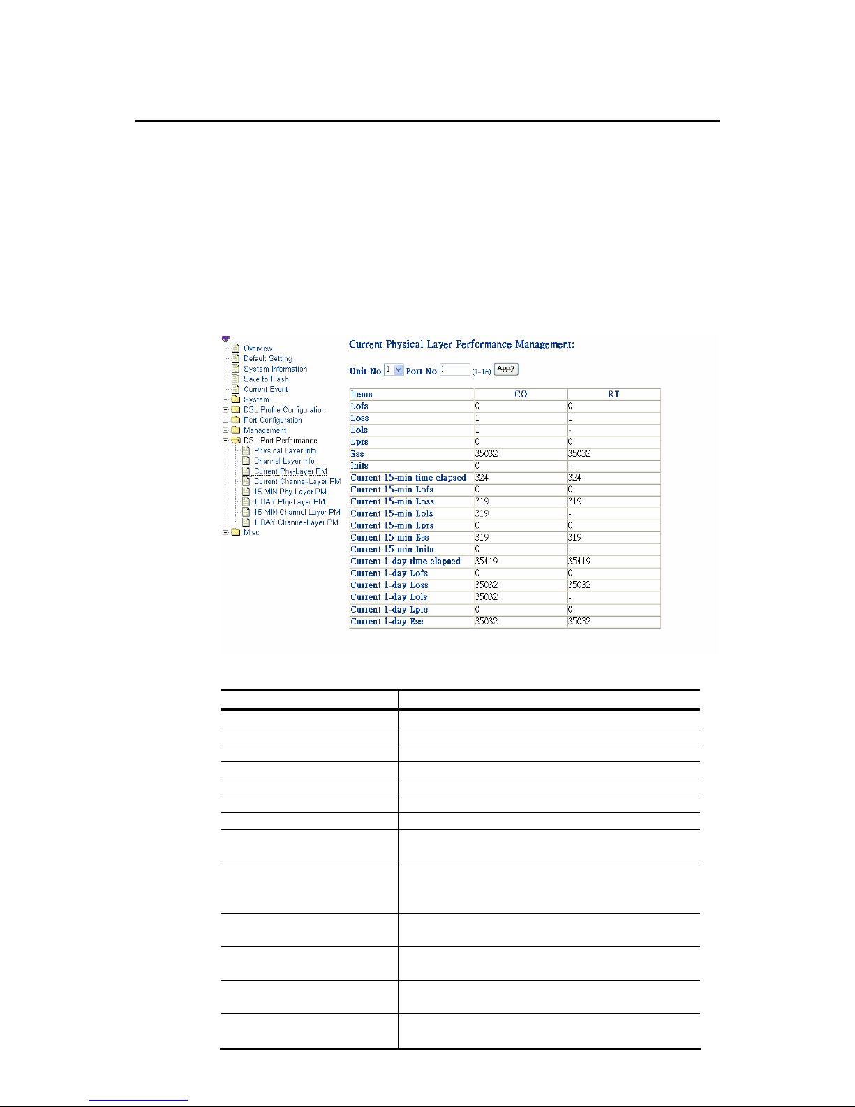
ADSL Physical Layer PM within Current 15 Minutes and a Day
Duration {Current Phy-Layer PM}
Allow you to view the physical layer performance collected within current 15
minutes and a day duration. The procedures are as follows:
1. Click on “Current Phy-Layer PM” of the DSL Port Performance Menu.
The Current Phy-Layer PM screen appears as follows:
Table 3-8 Current Phy-Layer PM Information Field Definitions
Field Definition
CO down stream
RT up stream
Lofs number of lof failures since reset.
Loss number of los failures since reset.
Lols number of lol failures since reset.
Lprs number of lpr failures since reset.
Ess number of error seconds since reset.
Inits number of initialization attempts since reset. it
includes both successful and failed attempts.
Current 15-min time
elapsed
number of seconds that have elapsed within
the current 15 minutes. a full interval is 900
seconds.
Current 15-min lofs number of seconds in the current 15-minute
interval during which lof was detected.
Current 15-min loss number of seconds in the current 15-minute
interval during which los was detected.
Current 15-min lols number of seconds in the current 15-minute
interval during which lol was detected.
Current 15-min lprs number of seconds in the current 15-minute
interval during which lpr was detected.
Page 53

ADSL IP DSLAM
45
Field Definition
Current 15-min ess number of error seconds in the current
15-minute interval.
Current 15-min inits number of inits in the current 15-minute
interval. it includes both successful and failed
attempts.
Current 1-day time elapsed number of seconds that have elapsed since
the beginning of the current 1-day interval.
Current 1-day lofs number of seconds in the current 1 day interval
during which lof was detected.
Current 1-day loss number of seconds in the current 1 day interval
during which los was detected.
Current 1-day lols number of seconds in the current 1 day interval
during which lol was detected.
Current 1-day lprs number of seconds in the current 1 day interval
during which lpr was detected.
Current 1-day ess number of error seconds in the current 1 day
interval.
Page 54
ADSL IP DSLAM
46
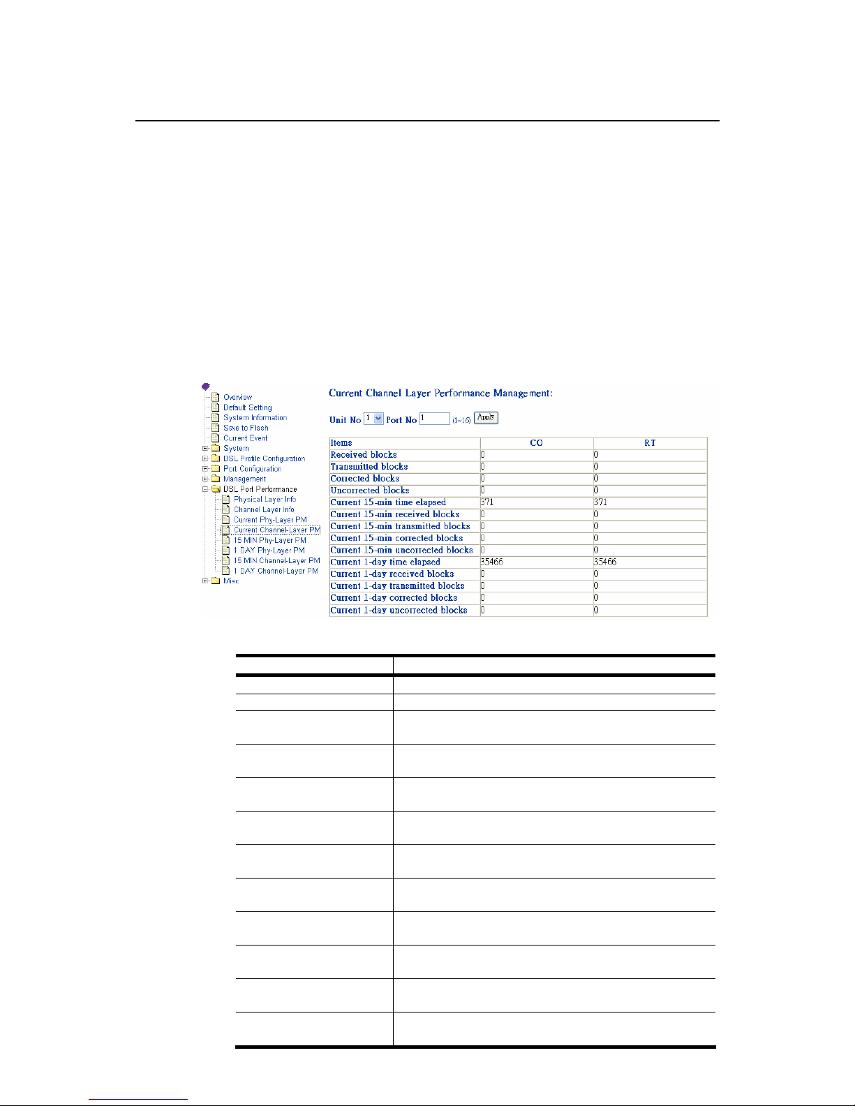
ADSL Channel Layer PM within Current 15 Minutes and a Day
Duration {Current Channel-Layer PM}
Allow you to view the channel layer performance collected within current 15
minutes and 1-day duration.
1. Click on “Current Channel-Layer PM” of the DSL Port Performance Menu.
The Current Channel-Layer PM screen appears as follows:
Table 3-9 Current Channel-Layer PM Information Field Definitions
Field Definition
CO down stream
RT up stream
Received blocks the total number of blocks of data received since
the last agent reset.
Transmitted blocks the total number of blocks of data transmitted
since the last agent reset.
Corrected blocks number of corrected blocks of data transmitted
since the last agent reset.
Uncorrected blocks number of corrected blocks of data transmitted
since the last agent reset.
Current 15-min time
elapsed
number of seconds that have elapsed since the
start of the current 15-minute interval.
Current 15-min
received blocks
number of blocks of data received during the
current 15-minute interval.
Current 15-min
Transmitted blocks
number of blocks of data transmitted during the
current 15-minute interval.
Current 15-min
corrected blocks
number of corrected blocks of data transmitted
during the current 15-minute interval.
Current 15-min
Uncorrected blocks
number of uncorrected blocks of data transmitted
during the current 15-minute interval.
current 1-day time
elapsed
number of seconds that have elapsed since the
start of the current day interval.
Page 55
ADSL IP DSLAM
47
Field Definition
Current 1-day received
blocks
number of blocks of data received during the
current day interval.
Current 1-day
transmitted blocks
number of blocks of data transmitted during the
current day interval.
Current 1-day corrected
blocks
number of corrected blocks of data transmitted
during the current day interval.
Current 1-day
uncorrected blocks
number of uncorrected blocks of data transmitted
during the current day interval.
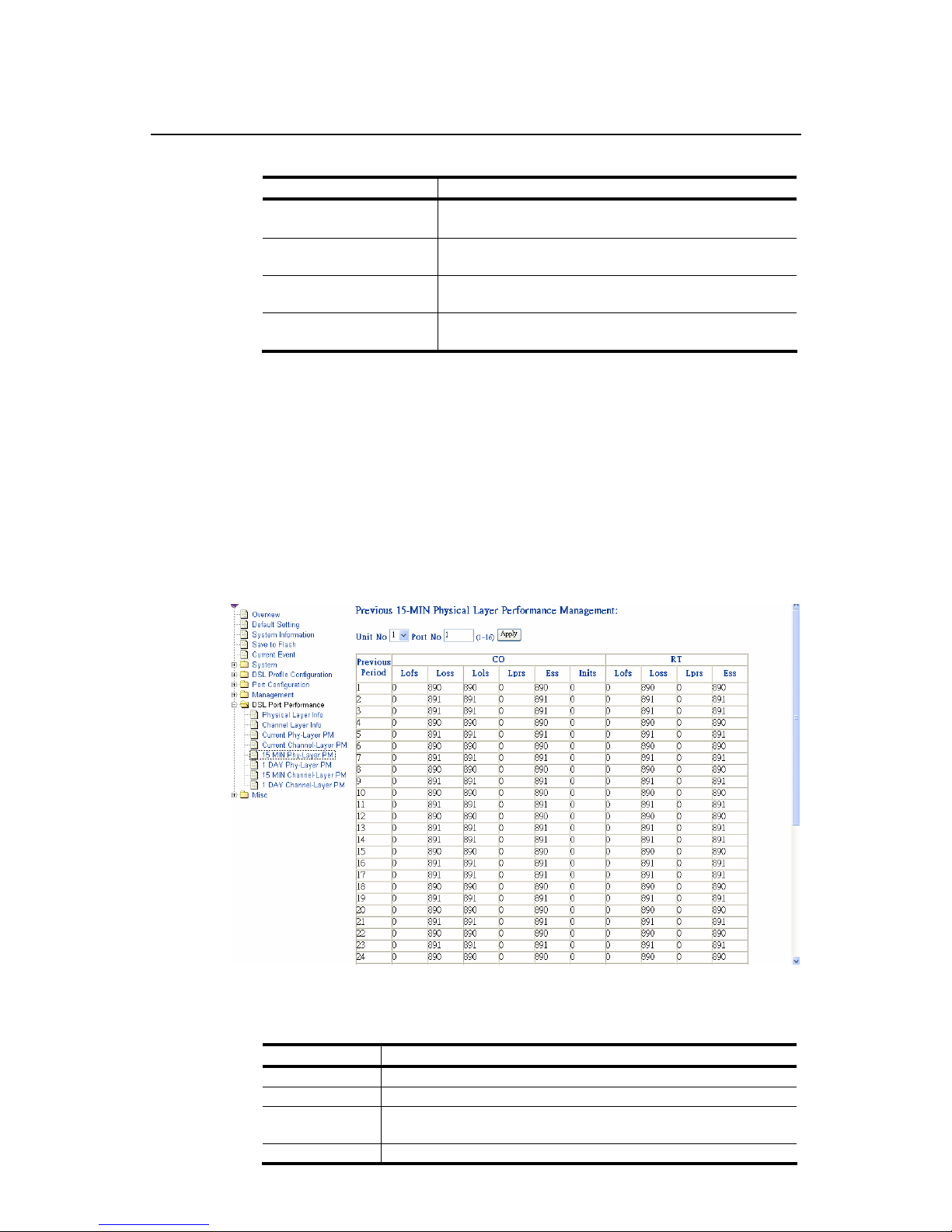
ADSL Physical Layer PM within Previous 15 Minutes Duration {15
MIN Phy-Layer PM}
Allow you to view the physical layer performance during previous 15 minutes
interval.
1. Click on “15 MIN Phy-Layer PM” of the DSL Port Performance Menu.
The 15 MIN Phy-Layer PM screen appears as follows:
Table 3-10 15 MIN Phy-Layer PM Information Field Definition
Field Definition
CO down stream
RT up stream
Lofs counts of lof since agent reset within previous 15-min
interval.
Loss counts of los since agent reset within previous 15-min
Page 56
ADSL IP DSLAM
48
interval.
Lols counts of lol since agent reset within previous 15-min
interval. (but only on atu-c side)
Lprs counts of lpr since agent reset within previous 15-min
interval.
Ess counts of es since agent reset within previous 15-min
interval.
Inits counts of adsl line initialization attempts since agent reset,
including both successful and failed attempts within
previous 15-min interval. (but only on atu-c side)
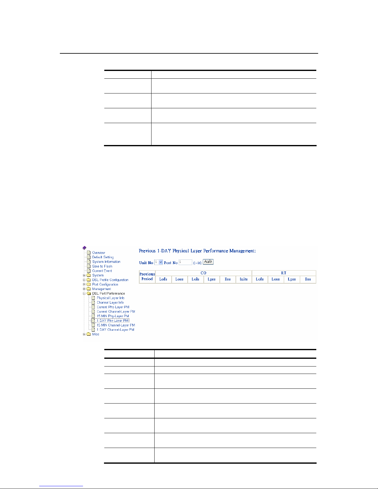
ADSL Physical Layer PM within Previous 1 Day Duration {1 DAY
Phy-Layer PM}
Allow you to view the physical layer performance during previous 1 day
interval.
1. Click on “1 DAY Phy-Layer PM” of the DSL Port Performance Menu.
The 1 DAY Phy-Layer PM screen appears as follows:
Table 3-11 1-DAY Phy-Layer PM Information Field Definition
Field Definition
CO down stream
RT up stream
lofs counts of lof since agent reset within previous 1day
interval.
loss counts of los since agent reset within previous 1day
interval.
lols counts of lol since agent reset within previous 1day
interval. (but only on atu-c side)
lprs counts of lpr since agent reset within previous 1day
interval.
ess counts of es since agent reset within previous 1day
interval.
inits counts of adsl line initialization attempts since agent
reset, including both successful and failed attempts
Page 57
ADSL IP DSLAM
49
within previous 1 day interval.(but only at atu-c side)
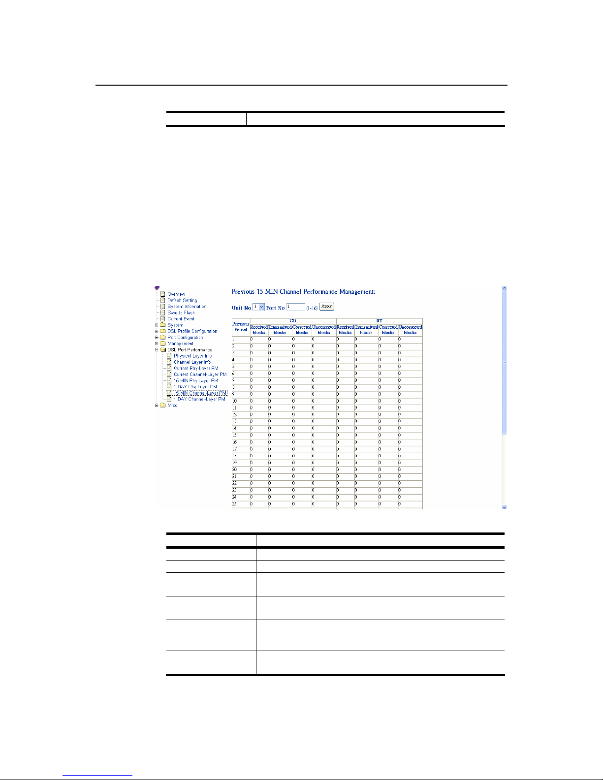
ADSL Channel Layer PM within Previous 15 Minutes Duration {15
MIN Channel-Layer PM}
Allow you to view the channel layer performance during previous 15 minutes
interval.
1. Click on “15 MIN Channel-Layer PM” of the DSL Port Performance Menu.
The 15 MIN Channel-Layer PM screen appears as follows:
Table 3-12 15 MIN Phy-Layer PM Information Field Definition
Field Definition
CO down stream
RT up stream
Received blocks the total number of blocks of data received during the
previous 15min interval.
Transmitted blocks the total number of blocks of data transmitted during
the previous 15min interval.
Corrected blocks number of corrected blocks of data transmitted during
the previous 15min interval.
Uncorrected blocks number of uncorrected blocks of data transmitted
during the previous 15min interval.
Page 58
ADSL IP DSLAM
50
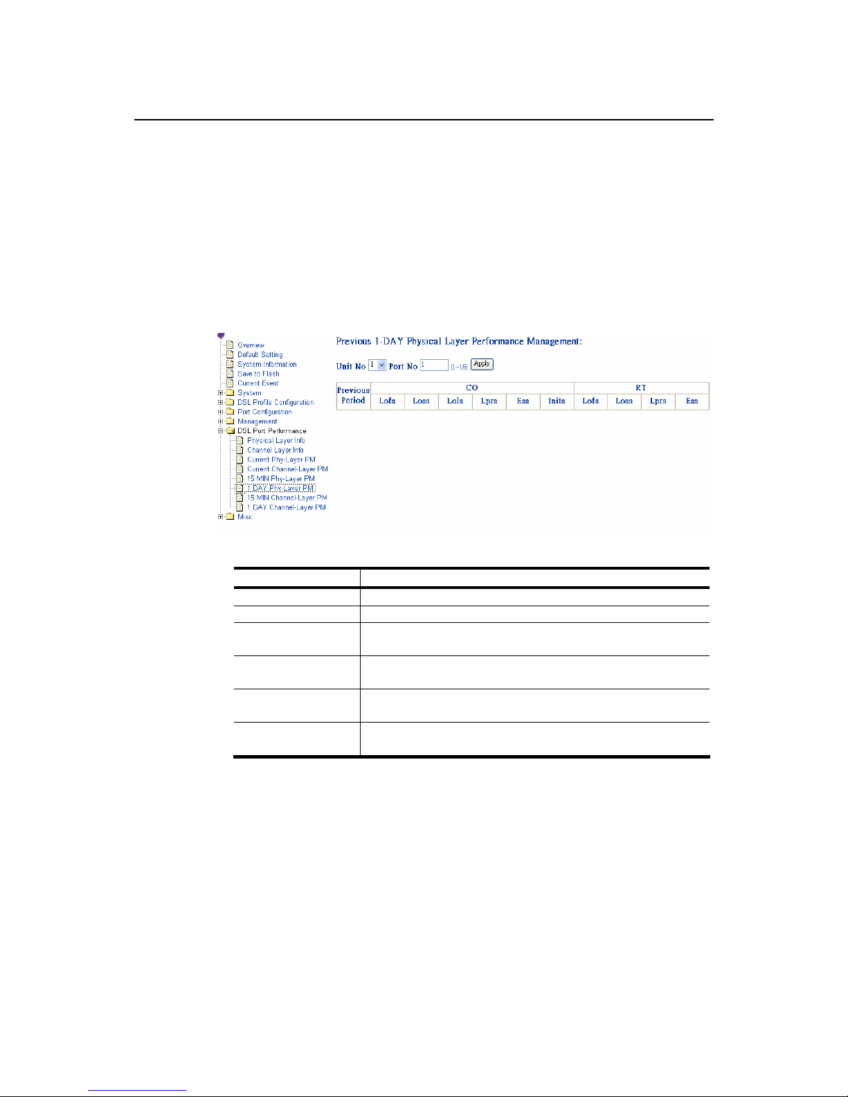
ADSL Channel Layer PM within Previous 1 Day Duration {1 DAY
Channel-Layer PM}
Allow you to view the channel layer performance during previous 1 day
interval.
1. Click on “1 DAY Channel-Layer PM” of the DSL Port Performance Menu.
The 1 DAY Channel-Layer PM screen appears as follows:
Table 3-13 1 DAY Phy-Layer PM Information Field Definition
Field Definition
CO down stream
RT up stream
Received blocks the total number of blocks of data received during the
previous 1day interval.
Transmitted blocks the total number of blocks of data transmitted during
the previous 1day interval.
Corrected blocks number of corrected blocks of data transmitted during
the previous 1day interval.
Uncorrected blocks number of uncorrected blocks of data transmitted
during the previous 1day interval.
Page 59
ADSL IP DSLAM
51
3.12 Miscellanea
This section covers miscellanea by selecting Misc from EmWeb Menu. It
includes:
IGMP Snooping Configuration {IGMP_Snooping Config}
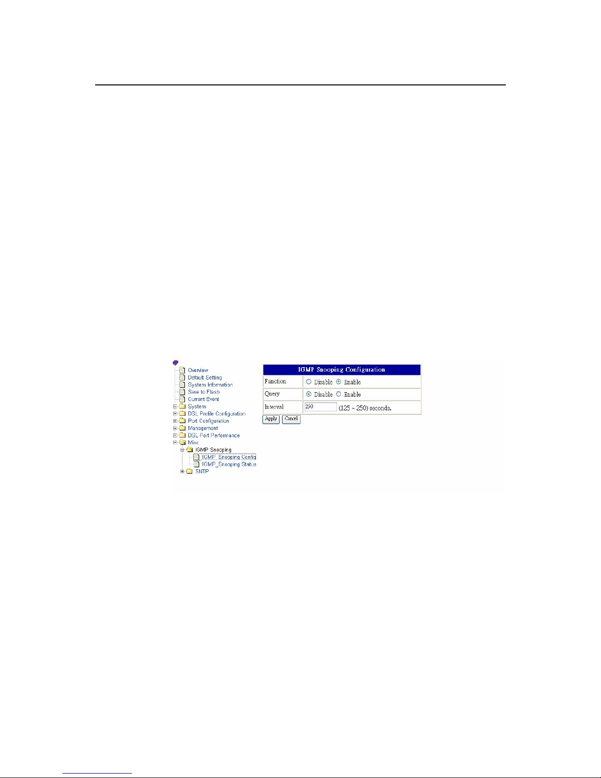
Allows you to view and modify IGMP Snooping Configuration. The procedure is
as follows:
1. Enter Misc Menu and the click on “IGMP Snooping Config” of IGMP
snooping menu.
2. The IGMP Snooping Config screen appears as follows:
3. Select the function is disable or enable.
4. Select the active query is disable or enable.
5. Define the active query interval, 125~250 seconds.
6. Click on Apply bottom to submit your configuration or Cancel bottom to
clear your configuration.
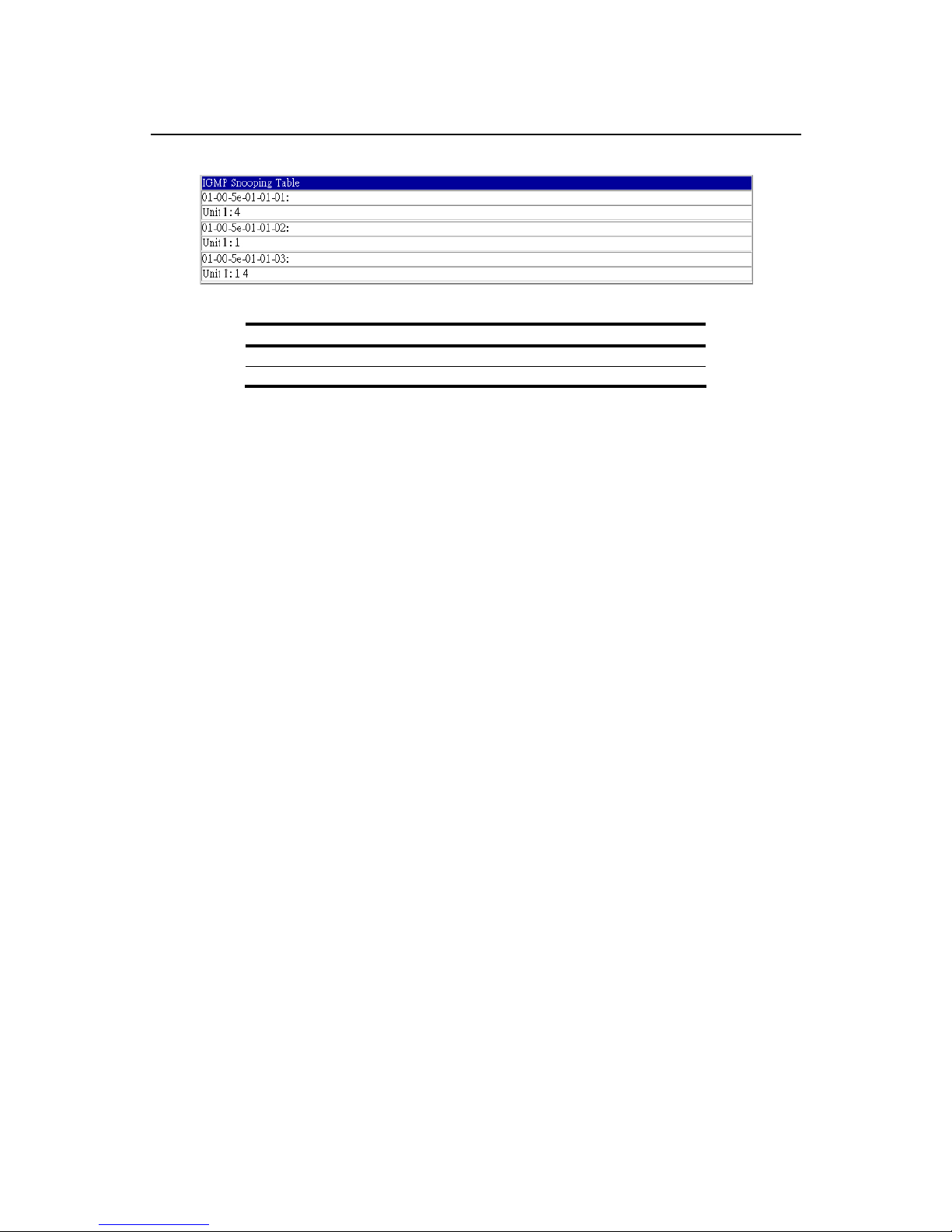
IGMP Snooping Status {IGMP_Snooping Status}
Allow you to view IGMP Snooping status. The procedure is as follows
1. Enter Misc Menu, and then Click on “IGMP Snooping Status” of IGMP
Snooping menu.
The IGMP Snooping Status screen appears as follows:
Page 60
ADSL IP DSLAM
52
Table 3-14 IGMP Snooping Table Definition
Items Description
Group Address IGMP group address.
Member of group Member included in groups.
Page 61
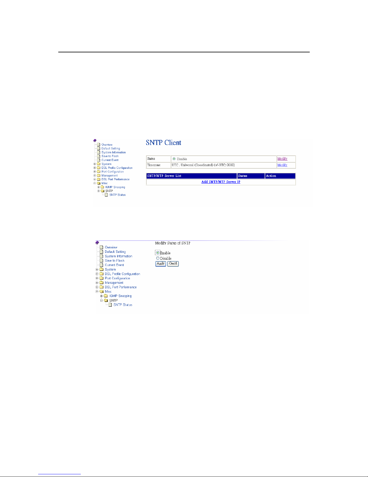
ADSL IP DSLAM
53
SNTP Status {SNTP Status}
Allow you to view the SNTP Client status and execute further configuration.
The procedure shows as follows.
1. Enter Misc Menu and click on “SNTP Status” of SNTP menu. The SNTP
screen appears as follows:
2. To configure the SNTP status, enable or disable, click on Modify, and then
the screen appears as follows:
3. Select Enable to activate SNTP and then click on Apply bottom to
confirm.
4. To configure the Time zone, click on Modify and then the screen appears as
follows:
Page 62
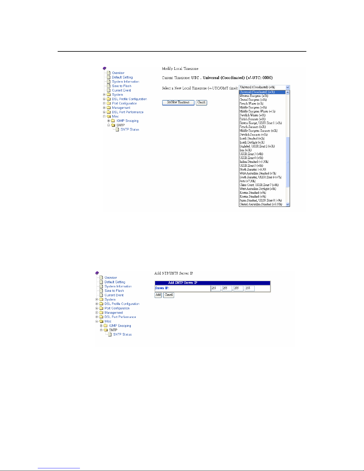
ADSL IP DSLAM
54
5. Select a new time zone and click on Set New Timezone button to submit
your setting.
6. If to add a SNTP/NTP Server IP, click on add SNTP/NTP Server IP, and the
screen appears as follows:
7. Set a new server IP and click on Add button to add the IP into the
SNTP/NTP server IP list or click on Cancel button to return to System
Date and Time screen.
Page 63

ADSL IP DSLAM
55
4. System Administration with CLI
4
Command Line Interface (CLI) is the primary user interface to Administrate the
system. CLI can be accessed either from the CID port or telnet session. All CLI
commands are simple strings designed for the Administrator to manage your
ADSL IP DSLAM easily.
4.1 Command Structure
There are three-level command structure used in the system. All commands
have the following general format:
IPDSLAM# <action> Identifier parameters
Action
Identify the specific function to be acted. For example, in the
case of viewing the information of 16
th
port of ADSL IP
DSLAM, you must enter the command “show port16”. “show”
is the <action>.
Identifier
Indicate the object of the specific function to be acted. For
example, in the case of viewing the information of 16
th
port,
you must enter the command “show port 16”; “port” is the
<identifier>.
Parameter
Usually indicate the destination or configuring values. In
parameter description, <> means the required fields in a
command, whereas [ ] and | are the optional fields in a
command. For example, in the case of viewing the
information of 16
th
port, you must enter the command “show
port 16” to; “16” is the parameters
Page 64

ADSL IP DSLAM
56
Table 4-1 CLI Command - Action List
<action> Description
show Used to view information of the selected identifier and
parameters.
add Used to add configuration of objects according to the identifier
and parameters. Parameters are used for selecting specific
facility and arguments. For example, “16” specifies the 16
th
port
of ADSL IP DSLAM.
config Used to set or modify existing configuration of objects
corresponding to the identifier and parameters. But lineprof
name -default and alarmprof name default can not be
configured.
delete Used to delete configuration of objects corresponding to the
identifier and parameters. If the delete action is confirmed, the
configuration of objects will no longer exist.
help Used to view the detailed usage of CLI commands.
history Used to view the list of CLI commands that the user have used.
reset Used to reset a port of system.
restart Used to restart the system.
save Used to save the configuration to Flash RAM.
default Used to restore the default setting to system.
upgrade Used to upgrade the system file.
exit Used to terminate the CLI.
Table 4-2 CLI Command – Identifier List
<identifier> Description
sysinfo
A
llow users to view or config the whole system information of
ADSL IP DSLAM.
sysip Allow users to view or config IP of system.
snmp Allow users to view or config VID and community for SNMP.
time
Allow users to view or config the current system date and
time.
sntp Allow users to view, add, delete or config sntp.
user The users’ information of system.
password Allow users to modify him (herself) password.
subscriber
Allow users to view, add, delete or config the basic
information of the subscriber of each port.
event Allow users to view the events of system.
trapdest Allow users to view, add or delete the trap destination.
manip Allow users to view, add, or delete management IP groups.
portfilter Allow users to view or config port-filter status.
port
Allow users to view or config status and information of each
port, or allow users to enable/disable port.
route
Allow users to view, add or delete the routing node in the
routing table.
connection
Allow users to view or config the connection information of
each port sorting by port id.
vid Allow users to view the vid information sorting by VLAN ID.
lineprof Allow users to view, add, delete or config ADSL line profile.
alarmprof
A
llow users to view, add, delete or config the alarm threshold
values in an ADSL.
adslline Allow users to view or config the information of ADSL line.
Page 65

ADSL IP DSLAM
57
adslchannel
Allow users to view the channel layer parameters of ADSL
lines.
adslphysical
Allow users to view the physical layer parameters of ADSL
lines.
adslchperf
Allow users to view the performance statistics collected on
channel layer of ADSL line.
adslchintl
Allow users to view the statistics information collected on
channel layer within 15-minutes or 1-day interval.
adslphperf
Allow users to view the performance statistics collected on
physical layer of ADSL lines.
adslphintl
Allow users to view the statistics information collected on
physical layer within 15-minutes or 1-day interval.
igmpconf Allow users to view or config the configurations of IGMP.
igmpgroup Allow users to view the IGMP groups.
igmppm Allow users to view and reset the IGMP PM.
ethermode Allow users to view and configure Ethernet rate mode
dhcpd Allow users to view and configure DHCP server
Table 4-3 Relation between <action> and <identifier>
<action> <identifier>
adslchannel adslchintl adslchperf adslline adslphintl
adslphperf adslphysical alarmprof connection event
lineprof manip port portfilter snmp
sysinfo sysip subscriber time trapdest
user vid rip igmps sntp
show
route ethermode dhcpd
alarmprof connection lineprof manip trapdest
add
user sntp
adslline alarmprof connection lineprof manip
password port portfilter snmp subscriber
sysinfo sysip time user sntp
config
ethermode dhcpd
user event trapdest connection lineprof
delete
alarmprof manip route sntp
Help show/add/config/delete/…… /show sysinfo/config time/……..
history None
reset port
restart None
Save None
Default None
Upgrade Enable / disable
exit None
Table 4-4 CLI Command – Parameter List
<action> <parameter> Description
all
A
llow you to view all
information.
show <identifier>
< port no.> Allow you to view the specified
port’s information.
Page 66

ADSL IP DSLAM
58
<action> <parameter> Description
< port no.> [c/r]
A
llow you to view the CO or RT
information by specifying a port
(1 ~ 16).
<action> <parameter> Description
add alarmprof <profile Name> Setting alarm profile name.
(alarmprof-atuc) <Thresh15MinLofs>
<Thresh15MinLoss>
<Thresh15MinLols>
<Thresh15MinLprs>
<Thresh15MinESs>
<InitFailureTrapEnable>
A
llow you to set the threshold
value of CO side alarms.
(alarmprof-atur) <Thresh15MinLofs>
<Thresh15MinLoss>
<Thresh15MinLprs>
<Thresh15MinESs>
Allow you to set the threshold
value of RT side alarms.
add connection < unit no./port no.> <vpi/vci>
<AdminStatus>[VID]
[Priority]
A
llow you to create the PVC by
specifying a port (1 ~ 16).
add lineprof <profile name> Setting Line profile name.
(lineprof-atuc) <RateMode>
<RateChanRatio>
<TargetSnrMgn>
<MinTxRate> <MaxTxRate>
<MaxInterleaveDelay>
Allow you to add ATU-C items
of line profile.
(lineprof-atur) <RateMode>
<RateChanRatio>
<TargetSnrMgn>
<MinTxRate> <MaxTxRate>
<MaxInterleaveDelay>
Allow you to add ATU-R items
of lineprof.
add manip <IP1> [musk] Allow you to define the
management IP
add trapdest <IP address> Allow you to define trap
destination.
add user <Username><Administrator|
operator|guest>
Allow you to create new
account of Administrator or
operator or guest.
add sntp server <IP> Allow you to add a SNTP IP
address.
add route <name><dest><mask><port
no>
Allow you to add a route
config adslline <port no.> <lineprof>
<alarmprof>
Modify ADSL line configuration
by arguments.
config alarmprof <profile Name> Modify existing alarm profile.
(alarmprof-atuc) <Thresh15MinLofs>
<Thresh15MinLoss>
<Thresh15MinLols>
<Thresh15MinLprs>
<Thresh15MinESs>
<InitFailureTrapEnable>
Modify the threshold value of
CO side alarms
Page 67

ADSL IP DSLAM
59
<action> <parameter> Description
(alarmprof-atur) <Thresh15MinLofs>
<Thresh15MinLoss>
<Thresh15MinLprs>
<Thresh15MinESs>
Modify the threshold value of
RT side alarms
config
connection
< port no.> <PVC1>
<PVC2> <AdminStatus>
[VID] [Priority]
Modify pvc (vpi/vci) and VLAN
ID by specifying a port.
config lineprof <profile name> Modify existing line profile.
(lineprof-atuc) <RateMode>
<RateChanRatio>
<TargetSnrMargin>
<MinTxRate> <MaxTxRate>
<MaxInterleaveDelay>
Modify the configuration of CO
side of line profile.
(lineprof-atur) <RateMode>
<RateChanRatio>
<TargetSnrMargin>
<MinTxRate> <MaxTxRate>
<MaxInterleaveDelay>
Modify the configuration of RT
side of line profile.
config manip <IP> [musk]
A
llow you to modify the existing
management IP
config password None Change the user’s password
config port <all|port#> <up | down> Set the state of ADSL port.
config portfilter <enable|disable> Port filttering configuration
config snmp <community> [SNMP VID] Modify the SNMP VID and
community.
config subscriber < port no.> Modify subscriber information
for specific port.
(subscriber) <subscriber name>
<telephone number> <Note>
Modify subscriber information
by arguments.
config sysinfo
(system name)
(location)
(contact)
(console name)
Modify the information of
system by modifying system
name, location, contact and
console name.
config sysip <IP> <submask> <gateway> Modify the IP arguments of
system.
config time <date> <time>
config user <User-name>
<Administraot|operator|gues
t
Modify user’s account and
privilege.
config igmps None Configure IGMP snooping
config sntp <enable/disable> Configure SNTP status
config sntp
timezone
<timezone> Configure local time zone
delete alarmprof <profile name> Delete ADSL alarm profile by
selecting alarm profile name.
delete
connection
</port no.> <vpi/vci> Delete pvc by selecting (vpi/vci)
of ADSL IP DSLAM port no.
delete event none Delete all event information
Page 68

ADSL IP DSLAM
60
<action> <parameter> Description
delete lineprof <profile name> Delete ADSL line profile by
selecting profile name.
delete manip <IP address> Delete the specific IP.
delete trapdest <IP address> Delete Trap destination IP
delete user <user name> Delete user information by
selecting user name.
Delete route <name> Delete all or one item of routing
table.
help Add, delete….. Show usage of commands
history none The used command.
reset port < all./port no.> Reset Port
restart none Restart system
save none Save configuration to Flash
Ram.
default none Restore the default setting.
upgrade enable/disable Enable/ disable upgrate
function
exit none Restore the default setting
Calling Commands
To recall commands from the history buffer, perform one of these tasks.
Command Task
The up arrow key Recall commands in the history buffer, beginning
with the most recent command. Repeat the key
sequence to recall successively older commands.
The down arrow key Return to more recent commands in the history
buffer after recalling commands with “the up arrow
key”. Repeat the key sequence to recall
successively more recent commands.
Page 69

ADSL IP DSLAM
61
4.2 General Configuration
Help Command
“Help” command can be used to get help specific to a command mode by
entering help <command> or help <command> <parameter>.
Command: help
History Command
“History” command is used for to trace the command all users have entered.
Command: history
Saving the System
Describes how to save system configuration you have defined to Flash RAM.
Command: save
Note: Before you restart the system, remember to save the system by entering
the command “save” or the system will restart at the previous settings.
Page 70

ADSL IP DSLAM
62
4.3 Event Viewing and Deleting
Displaying the Current Event
Describes how to display the current event of system.
Command: show event
Example: This example shows how to display the current status of system.
IPDSLAM # show event
------------------------------------------------------------------------------------- No Time Source Severity Description
------------------------------------------------------------------------------------- 1 2001/07/16 14:27:05 8 major loss threshold occurs
2 2001/07/16 14:27:15 5 inform port down
Table 4-5 “show event” Field Definition
Field Definition
No Index of each event.
Time The time when the event occurs.
Source The port where the event occurs.
Severity Priority of event (major/minor/inform)
Description Description of the event information.
Deleting the Event of ADSL IP DSLAM
Describes how to delete the event of system.
Command: delete event
Reset Port
Reset Port
Describes how to reset the specific port.
Command: reset port <all / port no.>
Example: This example shows how to reset the specific unit 1/ port 8.
Page 71

ADSL IP DSLAM
63
IPDSLAM # reset port 8
Yes or No <y/n>?
Restart the ADSL IP DSLAM
Describes how to restart the system without turning on/off power.
Command: restart
Example: This example shows how to restart the system.
IPDSLAM # restart
Yes or No <y/n>?
System is restarting now. Wait…
Note: Before you restart the system, be sure that you save all the
configurations by entering the command “save” or the system will start with the
previous settings.
Resetting all Configurations to Default Setting
Describes how to reset all configurations to default.
Command: default
Note: The system will return to the original default settings.
Example:
IPDSLAM # default
Danger!! This will affect your whole system.
Yes or No <y/n>?
You have restored the default setting to system.
System Upgrade
Describes how to enable or disable download without in-band management
channel (VLAN).
Command: upgrade <enable | disable>
Argument List:
Parameter type Description
Enable / disable Enable / disable upgrade mode
Page 72

ADSL IP DSLAM
64
Example: This example shows how to enable download without in-band
management channel.
IPDSLAM # upgrade enable
Yes or No <y/n>? y
System is in the “upgrade” mode now. You could start to upgrade the
system file.
Logging Out your ADSL IP DSLAM
Describes how to log out the system.
Command: exit
Note: Before you log out the system, be sure that you save all the
configurations by entering the command “save” or the system will start
with the previous settings.
4.4 Configuring Your ADSL IP DSLAM
System Configuration
Displaying Hardware and Software Information
Describes how to view the hardware and software information of ADSL IP
DSLAM.
Command: show sysinfo
Example: This example shows how to display the hardware and software
information of ADSL IP DSLAM. The following descriptions are default setting,
of which system name, location, contact and console name can be modified.
IPDSLAM # show sysinfo
System name: IPDSLAM
Location:
Contact:
Console name: IPDSLAM
1. Hardware version: A1
2. Software version: 1.00
Page 73

ADSL IP DSLAM
65
3. Serial number: 00-01-eb-02-02-7a
4. Description: Asotel DSA-3216 ADSL IP DSLAM
5. T emperature: Normal
Table 4-6 Sysinfo field definition
Field Definition
System name Alias name of ADSL IP DSLAM
Location Location of system
Contact Contact person for service and how to contact.
Console name Console name of the system.
Hardware version Hardware version of system.
Software version Software version of system.
Serial number Serial number of system.
Description Description of system.
FAN status Normal/Alarm
Modifying System Information
Describes how to modify the system information of system name, location,
contact and console name.
Command: config sysinfo
Argument List:
Parameter type Parameter data-type
and field
Description
System name String, <= 32 Name of ADSL IP DSLAM.
Location String, <=32 Location of system
Contact String, <= 32 Contact person and how to
contact
Console name String, <=16 (default:
ADSL IP DSLAM)
Name of console tittle.
(Empty for default)
Example: This example shows how to modify the name of system as ZTE 123,
console name as DSLAM and description of system as East Building
IPDSLAM # config sysinfo
(sysinfo-name)# ZTE 123
(sysinfo-location)# East Building
(sysinfo-contact)# Lee Gi, [email protected]
(sysinfo-console name)# DSLAM
System name: ZTE 123
Location: East Building
Contact: Lee GI, [email protected]
Console name: DSLAM
Yes or No <y/n>?
Page 74

ADSL IP DSLAM
66
Port-Filtering Configuration
Displaying Port-Filtering
Describes how to display the status of port-based VLAN.
Command: show portfilter
Example: This example shows how to view the status of port-based VLAN
IPDSLAM # show portfilter
Port filter: enable
Table 4-7 “show portfilter” Filed Definition
Items Description
Enable/ disable Enable: Allow each ADSL port to communicate back
and forth with the uplink Ethernet port only.
Disable: Allow all ADSL ports to communicate with
each other and also with the uplink Ethernet port.
Modifying Port-Filter
Describes how to configure port-filtering function whether to allow each ADSL
port communicate with the uplink Ethernet port only or communicate with each
other and so do with the Ethernet port.
Command: config portfilter <enable|disable>
Argument List:
Parameter type Parameter
data-type and field
Description
Status Enable/disable Enable: Allow each ADSL port to
communicate back and forth with the
uplink Ethernet port only.
Disable: Allow all ADSL ports to
communicate with each other and
also with the uplink Ethernet port.
Example: This example shows how to enable the portfilter and allow each
ADSL port to communicate with the uplink Ethernet port only.
IPDSLAM # config portfilter enable
Yes or No <y/n>?
This example shows how to disable the portfilter and allow all ADSL port to
communicate with each other and also with the uplink Ethernet port.
IPDSLAM # config portfilter disable
Yes or No <y/n>?
Page 75

ADSL IP DSLAM
67
Note: The default setting is “Enable”
IP Configuration
Displaying System IP
Describes how to view the system IP.
Command: show sysip
Example: This example shows how to display the system IP. The following
descriptions are default setting.
IPDSLAM # show sysip
IP: 192.168.10.2
Submask: 255.255.255.0
Gateway: 192.168.10.1
Table 4-8 Sysip Field Definition
Field Definition
IP IP of System
Submask Submask of system.
Gateway Gateway IP
Modifying System IP
Describes how to modify the system IP.
Command: config sysip <IP> <Submask> <Gateway>
Argument List:
Parameter type Parameter data-type
and field
Description
IP A.B.C.D IP of ADSL IP DSLAM
Submask A.B.C.D Submask of ADSL IP DSLAM
Gateway A.B.C.D Gateway of ADSL IP DSLAM
Example: This example shows how to modify the system IP as 192.168.10.100,
submask as 255.255.255.0 and gateway as 192.168.10.1.
IPDSLAM # config sysip 192.168.10.100 255.255.255.0 192.168.10.1
<IP>: 192.168.10.100
<Submask>: 255.255.255.0
<Gateway>: 192.168.10.1
Yes or No <y/n>?
Page 76

ADSL IP DSLAM
68
Time Configuration
Displaying Time
Describes how to display the current system time, system up time and period
Command: show time
Example: This example shows how to display the time of ADSL IP DSLAM.
IPDSLAM # show time
1.Current Time: 2001/07/16 11:05:35
2.System up time: 2001/7/15 10:00:25
3.System up period: 1 day 01:05:10
Table 4-9 Time Field Definition
Field Definition
Current Time Current system time.
System up time System up time.
System up period System up period.
Modifying Time
Describes how to modify the date and time of system.
Command: config time <date> <time>
Argument List:
Parameter type Parameter data-type
and field
Description
date yyyy/mm/dd e.g: 2001/07/13
time hh:mm:ss 24-hour time format
Example: This example shows how to modify the system time to
date:2001/07/13, time: 20:25:30.
IPDSLAM # config time 2001/07/13 20:25:30
Date: 2001/07/13
Time: 20:25:30
Yes or No <y/n>?
Page 77

ADSL IP DSLAM
69
SNTP configuration
Displaying SNTP
Describe how to display the SNTP.
Command: show sntp
Example: This example shows how to display the SNTP of ADSL IP DSLAM.
IPDSLAM# show sntp
SNTP Status: Disable
Time Reference Server IP addr:
Active Time Reference Server IP addr:0.0.0.0
-SNTP CLIENTS STATUS-
--------------------------------Clock Synchronized: FALSE
SNTP Standard Version Number: 4
SNTP Mode<s> Configured: Unicast
Local Time: Fri, 05 Mar 2004 – 09:40:27
Local Time Zone; UTC, Universal <coordinated> Time
Time Difference +- UTC: +0:00
Server Stratum: 0
Precision: 1 second
Server Reference ID: ----
IPDSLAM #
Adding a SNTP server address
Describe how to add a SNTP server address.
Command: add sntp server <IP>
Example:
IPDSLAM # add sntp server 192.168.100.88
IPDSLAM #
Modifying sntp
Describe how to modify the sntp.
Command: config sntp <enable/Disable>
Example:
Page 78

ADSL IP DSLAM
70
IPDSLAM # add sntp enable
IPDSLAM #
Modifying sntp timezone
Describe how to modify the local timezone.
Command: config sntp timezone<timezone>
Note: as to the abbreviation of timezone, please refer to the Appendix-B, the
SNTP timezone Abbreviation.
Example: config local time zone as NZT, New Zealand.
IPDSLAM # config sntp timezone NZT
IPDSLAM #
Changing the Password
This section describes how to change own password regardless of user’s
privilege.
Command: config password
Example: This example shows how the user changes his own password.
IPDSLAM # config password
Enter new password:********
Confirm password : ********
Yes or No <y/n>?
Page 79

ADSL IP DSLAM
71
4.5 Configuring DSL
Creating Line Profile and Alarm Profile
Creating DSL Profile
Describes how to create a DSL Profile.
Command: add lineprof <profile name>
Argument List:
Parameter type Parameter data-type and
field
Description
lineprof name String, <= 32 The name of ADSL line
profile.
Rate Mode Integer,
fixed : (1)
adaptAtStartup : (2)
Defines what form of
transmitting rate to be
adaptated.
Line Type Fast : (1)
Interleaved : (2)
The ADSL line type.
TargetSnrMargin Integer, 2 ~ 15 Target Signal / Noise
Margin.
MinTxRate Integer,
ATU-C: “32~ 8064”
ATU-R: “32 ~ 1024”
The minimum transmitting
rate of ATU-C side or
ATU-R side.
MaxTxRate Integer,
ATU-C: “32 ~8064”
ATU-R: “32 ~1024”
The maximum
transmitting rate of ATU-C
side or ATU-R side.
MaxInterleaveDelay Integer, 1,2,4,8,16,32,64 The value of Interleave
Delay for this channel.
Note:
1. If you select “Line Type” as “Fast”, you cannot select the value of
“MaxInterleaveDelay”. Please refer to the first example.
2. If you select “Rate Mode” as “Fixed”, the configuration of “MinTxRate”
and “MaxTxRate” must be the same. Please refer to the second
example.
Example1: This example shows how to create a DSL profile named
service512K64K.
IPDSLAM # add lineprof service512K64K
(lineprof-atuc)# 2 2 7 32 512 8
(lineprof-atur)# 2 2 7 32 64 8
ADSL Line Profile “SERVICE512K64K” content:
ATU-C:
Page 80

ADSL IP DSLAM
72
Rate Mode: adaptAtStartup
LineType: Interleaved
TargetSnrMargin: 7
MinTxRate: 32
MaxTxRate: 512
MaxInterleaveDelay: 8
ATU-R:
Rate Mode: adaptAtStartup
RateChanRatio: Interleaved
TargetSnrMargin: 7
MinTxRate: 32
MaxTxRate: 64
MaxInterleaveDelay: 8
Yes or No <y/n>
Example 2: This example shows how to create a DSL profile named fast.
IPDSLAM # add lineprof fast
(lineprof-atuc)# 1 1 6 768 768
(lineprof-atur)# 1 1 6 128 128
ADSL Line Profile “fast” content:
ATU-C:
Rate Mode: fixed
LineType: Fast
TargetSnrMargin: 6
MinTxRate: 768
MaxTxRate: 768
ATU-R:
Rate Mode: fixed mode
RateChanRatio: Fast
TargetSnrMargin: 6
MinTxRate: 128
MaxTxRate: 128
Yes or No <y/n>
Note: The configuration of default DSL profile named “DEFAULT” is as follows:
ATU-C:
1. RateMode: AdaptAtStartup
2. RateChanRatio: Interleaved
3. TargetSnrMargin: 6.0
4. MinTxRate: 32
5. MaxTxRate: 8064
6. MaxInterleaveDelay: 16
ATU-R:
1. Rate Mode: adaptAtStartup
2. RateChanRatio: Interleaved
3. TargetSnrMargin: 6.0
4. MinTxRate: 32
Page 81

ADSL IP DSLAM
73
5. MaxTxRate: 1024
6. MaxInterleaveDelay:16
Creating Alarm Profile
This section describes how to create an alarm profile.
Command: add alarmprof <profile name>
Argument List:
Parameter type Parameter
data-type and
field
Description
alarmprof name String, <= 32 The name of ADSL alarm profile.
Thresh15MinLofs Integer, 0 ~ 900 The threshold of the number of
“Loss of Frame Seconds” within
15 minutes performance data
collection period.
Thresh15MinLoss Integer, 0 ~ 900 The threshold of the number of
“Loss of Signal Seconds” within
15 minutes performance data
collection period.
Thresh15MinLols Integer, 0 ~ 900 The threshold of the number of
“Loss of Link Seconds” within 15
minutes performance data
collection period. (But only
ATU-C side)
Thresh15MinLprs Integer, 0 ~ 900 The threshold of the number of
“Loss of Power Seconds” within
15 minutes performance data
collection period.
Thresh15MinESs Integer, 0 ~ 900 The threshold of the number of
“Errored Seconds” within 15
minutes performance data
collection period.
InitFailureTrapenable enable / disable Enable or disable the Initial
Failure Trap. Default setting is
disable. (Only on ATU-C side)
Example: This example shows how to create an alarm profile named test.
IPDSLAM # add alarmprof test
(alarmprof-atuc)# 30 10 50 5 4 enable
(alarmprof-atur)# 30 2 2 5
ADSL Alarm Profile “test” content:
ATU-C:
Thresh15MinLofs: 30
Thresh15MinLoss: 10
Thresh15MinLols: 50
Thresh15MinLprs: 5
Thresh15MinESs: 4
Page 82

ADSL IP DSLAM
74
InitFailureTrapEnable: enable
ATU-R:
Thresh15MinLofs: 30 seconds
Thresh15MinLoss: 2 seconds
Thresh15MinLprs: 2 seconds
Thresh15MinESs: 5 seconds
Yes or No <y/n>
Note: the configuration of default dsl profile named “default” is as follows:
ATU-C:
1. Thresh15minlofs: 0
2. Thresh15minloss: 0
3. Thresh15minlols: 0
4. Thresh15minlprs: 0
5. Thresh15miness: 0
6. Initfailuretrapenable: enable
ATU-R:
1. Thresh15minlofs: 0
2. Thresh15minloss: 0
3. Thresh15minlprs: 0
4. Thresh15miness:0
Modifying DSL Profile and Alarm Profile
Modifying DSL Profile
Describes how to modify existing DSL profile but you cannot modify default
profile.
Command: config lineprof <profile name>
Argument List: the same as Creating DSL Profile. See page 71.
Example: This example shows how to modify the existing DSL line profile
named service512K64K.
IPDSLAM # config lineprof service512K64K
(lineprof-atuc)# 2 2 6 128 512 1
(lineprof-atur)# 2 2 6 32 64 1
ADSL Line Profile “service512K64K” content:
ATU-C:
Rate Mode: adaptAtStartup
LineType: Interleaved
TargetSnrMargin: 6
MinTxRate: 128
MaxTxRate: 512
MaxInterleaveDelay: 1
ATU-R:
Rate Mode: adaptAtStartup
Page 83

ADSL IP DSLAM
75
LineType: Interleaved
TargetSnrMargin: 6
MinTxRate: 32
MaxTxRate: 64
MaxInterleaveDelay: 1
Yes or No <y/n>?
Modifying Alarm Profile
Describes how to modify alarm profile but you cannot modify default profile.
Command: config alarmprof <profile name>
Argument List: Same as Creating Alarm Profile. See page 73
Example: This example shows how to modify the existing alarm profile test.
IPDSLAM # config alarmprof test
(alarmprof-atuc)#5 5 5 5 5 enable
(alarmprof-atur)#5 5 5 5 5
ADSL Alarm Profile “test” content:
ATU-C:
Thresh15MinLofs: 5
Thresh15MinLoss: 5
Thresh15MinLols: 5
Thresh15MinLprs: 5
Thresh15MinESs: 5
InitFailureTrapEnable: enable
ATU-R:
Thresh15MinLofs: 5
Thresh15MinLoss: 5
Thresh15MinLprs: 5
Thresh15MinESs: 5
Deleting a DSL Profile and Alarm Profile
Deleting DSL Profile
Describes how to delete a profile but you cannot delete the default profile.
Command: delete lineprof <profile name>
Example: This example shows how to delete existing line profile
service512K64K.
IPDSLAM # delete lineprof service512K64K
Yes or No <y/n>?
Page 84

ADSL IP DSLAM
76
Deleting Alarm Profile
Describes how to delete a alarm profile but you can’t delete the default
profile.
Command: delete alarmprof <profile name>
Example: This example shows how to delete existing alarm profile test.
IPDSLAM # delete alarmprof test
Yes or No <y/n>?
Displying a DSL Profile and Alarm Profile
Displaying DSL Profile
This section describes how to display all DSL profile or specific profile.
Command: show lineprof <all | line profile name>
Argument List:
Parameter Description
all Show all information.
Line profile name ADSL line profile name.
Example:This example shows how to display default line profile.
IPDSLAM # show lineprof default
ATU-C:
1. RateMode: adaptAtStartup
2. LineType: Interleaved
3. T ar getSnrMar gin: 6.0
4. MinTxRate: 32
5. MaxTxRate: 8064
6. MaxInterleaveDelay: 16
ATU-R:
1. Rate Mode: adaptAtStartup
2. RateChanRatio: Interleaved
3. T ar getSnrMar gin: 6.0
4. MinTxRate: 32
5. MaxTxRate: 1024
6. MaxInterleaveDelay: 16
Table 4-10 “show lineprof” Field Definition
Field Definition
RateMode The form of transmit rate adaptation
(fixed/adaptAtStartup)
LineType Fast or Interleaved mode.
Page 85

ADSL IP DSLAM
77
TargetSnrMargin Target Signal/Noise Margin. (dB)
MinTxRate The minimum transmitting rate of ATU-C side or
ATU-R side. (Kbps)
MaxTxRate The maximum transmitting rate of ATU-C side or
ATU-R side. (Kbps)
MaxInterleaveDelay The value of Interleave Delay for this channel.
(milli-seconds)
Displaying Alarm Profile
Describes how to display all alarm profile or specific alarm profile.
Command: show alarmprof <all | alarm profile name>
Argument List:
Parameter Description
all Show all information.
Alarm profile name ADSL alarm profile name.
Example: This example shows how to display the default alarm profile.
IPDSLAM # show alarmprof default
ATU-C:
1. Thresh15MinLofs: 0
2. Thresh15MinLoss: 0
3. Thresh15MinLols: 0
4. Thresh15MinLprs: 0
5. Thresh15MinEss: 0
6. InitFailureTrapenable: enable
ATU-R:
1. Thresh15MinLofs: 0
2. Thresh15MinLoss: 0
3. Thresh15MinLprs: 0
4. Thresh15MinEss: 0
Table 4-11 “show alarmprof” Field Definition
Items Description
Thresh15MinLofs The threshold of the number of “Loss of Frame
Seconds” within 15 minutes performance data
collection period. (seconds)
Thresh15MinLoss The threshold of the number of “Loss of Signal
Seconds” within 15 minutes performance data
collection period. (seconds)
Thresh15MinLols The threshold of the number of “Loss of Link
Seconds” within 15 minutes performance data
collection period. (seconds) (Only ATU-C side)
Thresh15MinLprs The threshold of the number of “Loss of Power
Seconds” within 15 minutes performance data
collection period. (seconds)
Page 86

ADSL IP DSLAM
78
Thresh15MinESs The threshold of the number of “Errored Seconds”
within 15 minutes performance data collection
period. (seconds)
InitFailureTrapenable The status of the Initial Failure Trap
(enable/disable). (seconds) (Only ATU-C side)
Page 87

ADSL IP DSLAM
79
4.6 Port Configuration
Enabling and Disabling a port
Describes how to enable and disable a port.
Command: config port <all | port no.> <up | down>
Argument List:
Parameter Description
all |port no. Select destination
up | down Enable/Disable ADSL port
Example: This example shows how to set the port 8 enable.
IPDSLAM # config port 8 up
Yes or No <y/n>? y
Attaching DSL Profile
Describes how to attach a profile to a port.
Command: config adslline < port no.> <lineProfile> <alarmProfile>
Argument List:
Parameter type Parameter
data-type and
field
Description
port no. (1 ~ 16) Indicated ADSL IP DSLAM port no.
LineProfile String, <=32 Specifies an ADSL line profile name.
AlarmProfile String, <=32 Specifies an ADSL alarm profile name.
Example: This example shows how to attach the profile “service 512K64K” and
alarm profile “test” to port 8, and displays the result:
IPDSLAM # config adslline 8 service512K64K test
LineProfile: SERVICE512K64K
AlarmProfile: TEST
Yes or No <y/n>?
Page 88

ADSL IP DSLAM
80
Displaying the Current Status and Information of ADSL Line
Displaying the Current Status of Line
Describes how to show the Administration, operating, alarm and trap status.
Command: show port <all |port no.>
Argument List:
Parameter Description
all Show all information.
port no. (1 ~ 16). Indicate the specific port.
Example: This example shows how to display the current status of port 8.
IPDSLAM # show port 8
1. Port ID: 1/8
2. Admin Status: up
3. Operating Status: up
4. Alarm Status: Normal
5. Trap: disable
The following example shows how to display the all port status.
IPDSLAM # show port all
Port ID Admin Status Operating Status Alarm Status Trap
--------------------------------------------------------------------------------------- 1 up up Normal enable
2 up up Normal enable
. … …
16 up up Normal enable
---------------------------------------------------------------------------------------Press ‘y’ for continue, ‘n’ for break and press Enter.
Table 4-12 “show port” Field Definition
Items Description
Port ID The specific ADSL IP DSLAM port no (port no.).
Admin Status The desired state of interface (up/down)
Operating Status The current operational state of interface
(up/down)
Alarm Status Alarm status…normal means “no alarm”
Trap enable/disable.
Displaying the information of ADSL Line
Describes how to get the information of line coding, line type, standard
compliance, channel mode and which line profile and alarm profile have
attached at the specific ADSL line.
Command: show adslline <all | port no.>
Page 89

ADSL IP DSLAM
81
Argument List:
Parameter Description
all Show all information.
port no. Port ID
Example: This example shows how to display the port 8 ADSL line information.
IPDSLAM # show adslline 8
1. LineCoding: Multimode
2. LineType: fastOrInterleaved
3. Standard Compliance: G.dmt
4. Channel Mode: fast
3. LineProfile: default
4.AlarmProfile: default
Table 4-13 “show adslline” Field Definition
Field Definition
LineCoding Multimode
LineType fastOrInterleaved
Standard Compliance ( G.dmt / G.lite / T1.413 / Multimode / other)
Channel Mode ( No Channel / fast / interleaved )
LineProfile Assigned ADSL line profile name.
AlarmProfile Assigned ADSL alarm profile name.
PVC Configuration
Creating PVC
Describes how to configure a permanent virtual connection, virtual LAN ID,
connection priority, Administration status and VLAN tag on the specific port.
Command: add connection < port no.> <vpi/vci> <up|down><b/r> [VID]
[priority]
Argument List:
Parameter type Parameter data-type
and field
Description
port no. (1 ~ 16) Indicated port no.
PVC (0 ~ 4095) /
(0 ~ 65535)
VPI/VCI
Admin Status up/down Used to up/down connection.
VID (optional) 2 ~ 4094 Optional VLAN ID, no element
represents the connection is
without VLAN tag.
RFC-1483 b/r Bridge or route
Priority (optional) 0 ~ 7 (Max:7 , Min:0) Optional Connection priority. No
VLAN tag, no priority.
Page 90

ADSL IP DSLAM
82
Example: This example shows how to configure the VPI-0, VCI-50, up
Administration status, enable VLAN tag with VLAN ID-4002 and highest
connection priority on port 8.
IPDSLAM # add connection 8 0/50 up b 4002 7
Port 8
PVC: 0/50
AdminStatus: up
VID: 4002
rfc1483 b<ridge>|r<oute>: b
Priority: 7
yes or No <y/n>?
This example shows how to configure the VPI-0, VCI-50, up Administration
status, and without VLAN tag on port 8 of unit 1
IPDSLAM # add connection 8 0/50 up
Port 8
PVC: 0/50
AdminStatus: up
yes or No <y/n>?
Note:
(1) Virtual Connection can be configured up to 2 connections on the same port
but the VLAN ID can not overlap with the existing VLAN ID.
(2) The default setting for PVC is 8/81, and you can modify and delete the
default setting.
(3) The default setting of VLAN ID is without VLAN tag.
(4) On the same port, one PVC or two PVCs can be created. On the creation of
one PVC, the configuration of VLAN ID can either be enabling VLAN tag or
disabling VLAN tag. On the creation of two PVCs, the configuration of
VLAN ID can either be enabling both VLAN tags or just disabling VLAN tag
on a PVC whereas the other will remain with VLAN tag. The situation of
both PVC without VLAN tag cannot be configured. Please refer to the table
4-13 for understanding ways of PVC configuration either with VLAN tag or
without VLAN tag:
Table 4-14 Ways of PVC configuration either with VLAN tag or without VLAN tag
Port 1
st
PVC 2nd PVC
With VLAN tag With VLAN tag
Without VLAN tag
The same
port
Without VLAN tag With VLAN tag
Page 91

ADSL IP DSLAM
83
Modifying PVC
Describes how to modify the virtual connection of the port.
Command: config connection < port no.> <vpi_old/vci_old>
<vpi_new/vci_new> <up|down><b/r> [VID] [priority]
Argument List:
Parameter type Parameter data-type
and field
Description
PVC_old 0 ~ 4095(vpi) /
0 ~ 65535(vci)
Existing old ATM PVC
PVC_new 0 ~ 4095(vpi) /
0 ~ 65535(vci)
New ATM PVC you want to
modify.
Others Same as Creating PVC. See page 81
Example: This example shows how to modify the previous example of This
example shows how to modify the previous example of “PVC-0/35,
AdminStatus-up, VID-4002, Priority-7” to “PVC-0/80, AdminStatus-up,
bridge”.
IPDSLAM # config connection 3 0/35 0/80 up b 300 7
Port 8:
PVC: 0/35 -> 0/80
AdminStatus: up
rfc1483 b<ridge>|r<oute>: b
VID:300
Priority:7
yes or No <y/n>?
Deleting PVC
Describes how to delete virtual connection you set, including the default
setting.
Command: delete connection < port no.> <vpi/vci>
Argument List:
Parameter type Parameter data-type and
field
Description
port no. (1 ~ 16) Indicated ADSL IP
DSLAM port no.
PVC (0 ~ 4095) / (0 ~ 65535) VPI/VCI
Example: This example shows how to delete the connection of port 8.
IPDSLAM # delete connection 8 0/50
Yes or No <y/n>?
Page 92

ADSL IP DSLAM
84
Displying PVC
Sorted by Port ID
Describes how to display existing virtual connection on each port and sorted by
port ID.
Command: show connection <all | port no.>
Argument List:
Parameter Description
all Show all information.
port no. (1 ~ 16). Indicate the port no.
Example: This example shows how to display the virtual connection of port 8.
IPDSLAM # show connection 1/8
Port ID PVC VID Priority Admin OpStatus 1483 mode
---------------------------------------------------------------------------------- 8 0/40 4000 6 up up bridge
8 8/81 9 7 up down bridge
------------------------------------------------------------------------------------
Table 4-15 “show connection” Field Definition
Items Description
Port ID The specific ADSL IP DSLAM port no.
PVC VPI/VCI
VID VID.
Priority The priority of this connection. (Max: 7 / Min:0)
Admin Status The Admin status of each connection (up/down).
OpStatus The operating status of each connection (up/down).
1483 mode The RFC-1483 mode (bridge/route)
Sorted by VID
Describes how to display existing virtual connection on each port and sorted by
VID.
Command: show vid <all | port no.>
Argument List:
Parameter Description
all Show all information.
port no. (1 ~ 16). Indicate the specific port no.
Example: This example shows how to display all virtual connection and sorted
by increasing VID.
Page 93

ADSL IP DSLAM
85
IPDSLAM # show vid all
----------------------------------------------------------------------------------- VID Port ID PVC Priority Admin Status Operating Status
----------------------------------------------------------------------------------- 4081 1/1 0/40 7 down down
4082 1/2 0/40 7 up up
4083 1/3 0/41 7 up up
.. .. .. .. .. ..
..
-----------------------------------------------------------------------------------Press ‘Y’ to continue, ‘N’ to break then press Enter.
Table 4-16 “show vid” Field Definition
Field Definition
VID VID.
Port ID The ADSL IP DSLAM port no.
PVC vpi/vci.
Priority The priority of this connection. (Max:7 / Min:0)
Admin Status The desired state of each connection (up/down)
Operating Status The current operational state of each connection
(up/down)
Subscriber Configuration
Displaying the Information of Subscriber
Describes how to view the information of subscriber of each port.
Command: show subscriber <all | / port no.>
Argument List:
Parameter Description
all Show all information.
port no. Port ID
Example: This example describes how to view the subscriber information on
specific port.
IPDSLAM # show subscriber 8
1. Subscriber name: pantagon
2. Telephone number: 4236125861
3. Note: Ok
Table 4-17 “show subscriber” Field Definition
Field Definition
Subscriber name Subscriber name of this port.
Page 94

ADSL IP DSLAM
86
Telephone number Telephone number of this port.
Note The description of subscriber of this port.
Modifying the Information of Subscriber
Describes how to modify the information of subscriber by specifying port no.
Command: config subscriber <port no.>
Argument List:
Parameter type Parameter
data-type and field
Description
port no. (1 ~ 16) Indicated ADSL IP DSLAM port
no.
Subscriber name String, <= 15 The desired subscriber name
Telephone number String, <= 11 The desired telephone number
Note String, <= 20 Remarks
Page 95

ADSL IP DSLAM
87
Example: This example shows how to modify the subscriber description of port
7.
IPDSLAM # config subscriber 7
(subscriber) help
< Subscriber name > < Telephone number > < Note >
(subscriber) adms 2148485965 Test_Again.
ADSL port “1/7” subscriber inform ation:
Subscriber name: adms
Telephone number: 2148485965
Note: T est_A gain.
Yes or No <y/n>?
Routing Table configuration
The following route commands, including show route, add route and delete
route, allow user to configured, if the RFC-1483 mode is configured as “Route”
in the PVC Configuration. They will be introduced as follows.
Displaying all routes
Describe how to view all routes in the routing table.
Command: show route
Argument List:
Parameter type Parameter
data-type and field
Description
Name String, <=10 Name of the route
Example:
IPDSLAM # show route
Name Destination Subnet mask GW(port no)
------------------------------------------------------------------------------------------------ grape 192.168.100.36 255.255.255.255 12
banana 192.168.100.35 255.255.255.255 3
apple 192.168.100.0 255.255.255.0 1
Page 96

ADSL IP DSLAM
88
Add a route
Describe how to add a roué into the routing table.
Command: add route <name><dest><mask><port no>
Example:
IPDSLAM # add route best 192.168.100.55 255.255.255.255 8
name: best
dest; 192.168.100.55
mask: 255.255.255.255
port: 8
Yes or No <y/n>?
Delete a route
Describe how to add a roué into the routing table.
Command: add route <name>
Example:
IPDSLAM # delete route best
name: best
Yes or No <y/n>?
Page 97

ADSL IP DSLAM
89
4.7 Management Configuration
Configuring SNMP Access Parameters
Displaying SNMP
Describes how to display the information of SNMP.
Command: show snmp
Example: This example shows how to display the information of SNMP.
IPDSLAM # show snmp
1.VID: 4094
2.Community: public
Table 4-18 “show snmp” Field Definition
Field Definition
VID SNMP VID
Community SNMP Community
Modifying SNMP
Describes how to modify the SNMP.
Command: config snmp <community> [VID]
Argument List:
Parameter type Parameter data-type
and field
Description
Community String, <32 SNMP Community
VID 2 ~ 4094 VID for SNMP.
Note: The community string is case-sensitive.
Example: This example shows how to modify SNMP with community string
“public” and no VID
IPDSLAM # config snmp public
VID: 0
community: public
Yes or No <y/n>?
This example shows how to modify SNMP with the configuration of community
string - “private” and VID – “4025”
Page 98

ADSL IP DSLAM
90
IPDSLAM # config snmp public 4025
VID: 4025
community: public
Yes or No <y/n>?
Configuring Trap IP
Creating Trap IP
Describes how to create the destination of trap IP.
Command: add trapdest <IP>
Argument List:
Parameter type Parameter data-type
and field
Description
IP A.B.C.D IP address
Note: The trap IP can be created maximum up to 5 traps.
Example: This section describes how to create the trap IP as 210.61.88.2
IPDSLAM # add trapdest 210.61.88.2
Yes or No <y/n>
Displaying SNMP Trap
Describes how to display the IP of destination that SNMP trap reached.
Command: show trapdest
Example: This example shows how to display the IP of destination that SNMP
trap reached.
IPDSLAM # show trapdest
Trap destination IP as follows:
192.168.100.12
192.168.100.100
Table 4-19 “show trapdest” Field Definition
Field Definition
IP A.B.C.D (Max: 5 trap IP)
Deleting SNMP Trap
Describes how to delete a specific trap IP.
Page 99

ADSL IP DSLAM
91
Command: delete trapdest <IP address>
Example: This example shows how to delete the trap IP 192.168.0.100.
IPDSLAM # delete trapdest 192.168.0.100
Yes or No <y/n>?
Configuring Management IP
Creating Management IP
Describes how to create the management IP.
Command: add manip <IP address> <mask>
Argument List:
Parameter type Parameter data-type
and field
Description
IP address A1.A2.A3.A4 IP address
<group> G1.G2.G3.G4 Group mask
Note:
(1) The management IP can be created up to 5 group of IPs at most no matter
you set the group mask or not.
(2) No management IP is configured in default setting, i.e., any IP can access to
your ADSL IP DSLAM
Example: This example shows how to create a group management IP and let
all IPs within the range of “IP address“ and “mask” able to access to your
ADSL IP DSLAM.
IPDSLAM # add manip 192.168.100.1 255.255.255.0
Yes or No <y/n>?
Displaying Management IP
Describes how to display the management IP.
Command: show manip
Example: This example shows how to display existing management IP.
ADSL IP DSLAM # show manip
IP Address Mask
Page 100

ADSL IP DSLAM
92
------------------------------------------------------------------
192.168.0.1 255.255.255.128
192.168.100.1 255.255.255.0
210.67.0.128 255.255.255.128
------------------------------------------------------------------
Table 4-20 “show manip” Field Definition
Field Definition
IP Address Mask
Deleting Management IP
Describes how to delete the management IP.
Command: delete manip <IP address>
Argument List:
Parameter type Parameter data-type
and field
Description
IP address A1.A2.A3.A4 IP address
Example: This example shows how to delete management IP group of
192.168.0.1
IPDSLAM # delete manip 192.168.0.1
Yes or No <y/n>?
 Loading...