

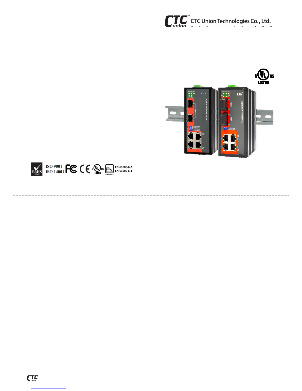
CTC Union IGS-401F, IGS-402F, IGS-402S, IGS-401F-E, IGS-402F-E Quick Installation Manual
...Page 1
CTC Union Technologies Co., Ltd.
Far Eastern Vienna Technology Center
(Neihu Technology Park)
8F, No. 60 Zhouzi St., Neihu District, Taipei 114
Taiwan
©2013 CTC Union Technologies Co., Ltd.
All trademarks are the property of their respective owners.
Technical information in this document is subject to change without notice.
Introduction
IGS-401F/402F(S) models are non-managed Gigabit Ethernet
switches that provide stable and reliable Ethernet transmission.
Housed in rugged DIN rail or wall mountable enclosures, these
switches are designed for harsh environments, such as industrial
networking and intelligent transportation systems (ITS) and are
also suitable for many military and utility market applications
where environmental conditions exceed commercial product
specifications. Standard operating temperature range models
(-10°C to 60°C) and wide operating temperature range models
(-40°C to 75°C) fulfill the special needs of industrial automation
applications.
Features
• Redundant dual DC inputs 12/24/48VDC
• IP30 rugged metal housing
• Wide temperature range -40°C~75°C (-E model)
• Support for Ethernet jumbo frames
• DIP switch enable/disable broadcast storm filter
• UL60950-1, CE, FCC, EN50121-4 Rail traffic
• Industrial EN61000-6-2 EMS, EN61000-6-4 EMI
Specifications
Ethernet Interface
• Connector: RJ-45 (shielded)
• 4 ports
• Auto MDI/MDI-X
• Speed: 10/100/1000Base-T (Auto)
• Duplex: Full/Half (Auto-negotiation per IEEE802.3u)
• Supports IEEE802.3x Flow Control
• Store & Forward Switch
• Switching Fabric: 10Gbps non-blocking (IGS-401F); 12Gbps
non-blocking (IGS-402F & IGS-402S)
• Packet buffer: 1Mb
• Standards: IEEE802.3, 802.3u, 802.3x, 802.3ab, 802.3z
• 8K MAC table
• MTU: 64~10240 bytes
• Broadcast Storm protection (enable/disable by DIP)
Quick Installation Guide
IGS-401F, IGS-402F, IGS-402S
IGS-401F-E, IGS-402F-E, IGS-402S-E
Industrial Grade Gigabit Ethernet Switches
Specifications (cont.)
Optical Ethernet Interface
• 1000Base-X, 1-port (IGS-401F), 2 ports (IGS-402F & IGS-402S)
• Fixed SC connectors (IGS-401F & IGS-402F)
• Pluggable SFP x 2 (IGS-402S)
• Multimode (2km) 50/125um, 62.5/125um
• Single mode (30km or 50km) 9/125um
• Wavelength: 1310nm (S/M or M/M)
Power
• Absolute range: 9.6VDC~60VDC
• Reverse polarity protection: Yes
• Dual power inputs: Yes
• Connector: removable terminal block
• Consumption: Max. 7.79W (IGS-401F); Max. 7.83W (IGS-402F
& IGS-402S)
Mechanical
• Water & Dust Proof: IP30 Protection
• Dimensions: 106 x 62.5 x 135mm (D x W x H)
• Mounting: DIN-Rail, Wall Mount (kits included)
• Weight: 670 g (IGS-401F); 680 g (IGS-402F & IGS-402S)
Environmental
• Operating Temperature: -10°C~60°C, -40°C~75°C (wide temp.
for -E model)
• Storage Temperature: -40°C~85°C
• Humidity: 5%~95% (non-condensing)
Certifications
• EMI: FCC Part 15 sub B class A, EN55022 Class A, EN61000-6-4
• EMS (Electromagnetic Susceptibility):
EN61000-6-2 Immunity for Industrial Environment
EN61000-4-2 (ESD) Level 3,Criteria B
EN61000-4-3 (RS) Level 3,Criteria A
EN61000-4-4 (Burst) Level 3,Criteria A
EN61000-4-5 (Surge) Level 3,Criteria B
EN61000-4-6 (CS) Level 3,Criteria A
EN61000-4-8 (Magnetic Field) Level 3,Criteria A
• Safety: UL60950-1
• Railway Traffic: EN50121-4
• Shock: EN60068-2-27
• Freefall: EN60068-2-32
• Vibration: EN60068-2-6
• MTBF: 407,596 hours (IGS-401F); 391,633 hours (IGS-402F);
438,031 hours (IGS-402S)
V1.3
To download this QIG or a more complete user manual, please visit
http://www.ctcu.com/Industrial/
w w w . c t c u . c o m
Page 2
Connectors
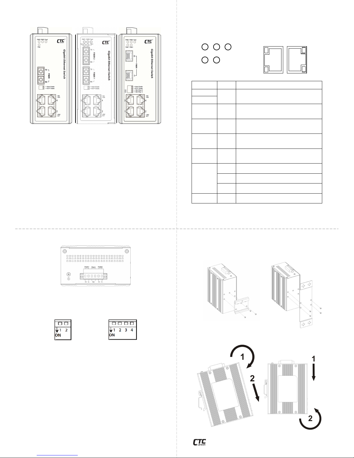
IGS-401F IGS-402F IGS-402S
All models have four electrical LAN ports (labeled 1, 2, 3, 4) that
utilize shielded RJ-45 connectors. These ports support
10/100/1000M Auto Negotiation and Auto MDI/MDI-X Ethernet.
IGS-402F gigabit optical ports (Fiber 1 / Fiber 2) use fixed
transceivers with SC or ST optical connections for multimode or
single mode fiber depending on model. (IGS-401F model has only
one fiber port.)
IGS-402S model provides SFP cages and supports dual rate,
125Mbps or 1.25Gbps SFP modules, inserted into Fiber 1 and
Fiber 2 ports. Dual rate support allows use of specific SFP modules
for fiber connection to other gigabit Ethernet (1000Base-X)
equipment or to legacy Fast Ethernet fiber (100Base-FX).
Power, Alarm and DIP switch
A removable terminal block provides both power and alarm
connections. Power can be provided through the dual inputs from
separate sources. One electrical relay can be wired into an alarm
circuit. The relay is connected as Normally Closed (will open upon
alarm condition).
IGS-401F/402F uses a 2-pole DIP switch for configuration, while
the IGS-402S uses a 4-pole DIP switch for configuration. Each pole
of the switch has the following functions:
1. Alarm Enable: When 'ON' this switch will disable alarm relay
and fault LED if there is a power failure in one supply. If only
connecting to a single power source, place this switch 'ON' to
disable alarm.
2. BSP Enable: When 'ON' this switch will disable the broadcast
storm protection feature which is enabled by default.
3. Fiber 2: This dual rate fiber port (IGS-402S ONLY) supports
optical Ethernet rate of 100M or 1G, depending on the setting
and the inserted SFP module. When set to 'ON', the port supports
Fast Ethernet rate and should use an SFP rated for 125~155Mbps.
When set 'OFF', the port is configured for gigabit Ethernet and
requires a 1.25Gbps SFP module.
4. Fiber 1: The same settings as for Fiber 2 port.
LED Indicators
IGS-401F and IGS-402F(S) have LEDs on the front face that
report the condition of power, fault, Fiber link, LAN link and speed.
LED Color
Definition
PWR1
Green
L
it if power is connec
ted and active at
the PWR1/PWR2 input terminal
connection.
PWR2
Fault Amber
Lit
if one of the power inputs has fault
condition and as long as DIP switch #1 is
OFF.
Fiber Green
L
it when the fiber port has an optical link
and will flash when there is Ethernet
traffic
. (IGS-401F)
Fiber 1 Green
L
it when the fiber 1 port has an optical
link and will flash when there is Ethernet
traffic
. (IGS-402
F & IGS
-
402S)
Fiber 2 Green
Lit
when the fiber 2 port has an optical
link and will flash when there is Ethernet
traffic.
(IGS-402
F & IGS
-
402S)
100/1000
Off
R
emain off if the connected speed is
10M.
Green
L
it when the LAN connected speed is
100M.
Amber
L
it when the LAN connected speed is
1000M.
LINK/ACT Green
L
it
when the LAN port has a link and will
flash when
there is Ethernet traffic.
Installation
IGS-401F/402F(S) comes with both wall mount and DIN rail
hardware brackets. When installing the DIN rail bracket, be sure
to correctly align the orientation pin.
DIN Rail Wall Mount
IGS-401F/402F(S) with DIN Rail bracket has a steel spring in the
upper rail of the bracket. This spring is compressed for mounting
and un-mounting by applying downward force.
mounting un-mounting
w w w . c t c u . c o m
PWR 1 PWR 2 Fault
Fiber 1 Fiber 2 LINK/
ACT
100/
1000
LINK/
ACT
100/
1000
 Loading...