

Page 1
Installation
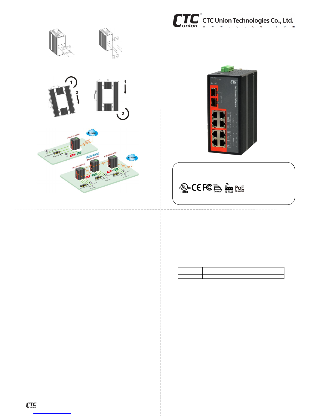
IFS-802GS-8PH(E) can be mounted on the wall or installed in DIN rail
depending on your installation needs. When installing the wall-mounting
bracket (optional accessory) and DIN rail bracket, be sure to correctly align the
orientation pin.
Figure 9. DIN Rail Figure 10. Wall Mount
IFS-802GS-8PH(E) with DIN Rail bracket have a steel spring in the upper rail
of the bracket. This spring is compressed for mounting and un-mounting by
applying downward force.
Figure 11. Mounting Figure 12. Un-mounting
Application
Figure 13. Ethernet Switch Transmission
Introduction
IFS-802GS-8PH & IFS-802GS-8PHE are unmanaged industrial grade
Fast Ethernet PoE switches that provide stable and reliable Ethernet
transmission. Housed in rugged DIN rail or wall mountable enclosures,
these switches are designed for harsh environments, such as industrial
networking and intelligent transportation systems (ITS) and are also
suitable for many military and utility market applications where
environmental conditions exceed commercial product specifications.
Standard operating temperature range models (-10°C~60°C) and wide
operating temperature range models (-40°C~75°C) fulfill the special
needs of industrial automation applications.
Package List
IFS-802GS-8PH(E) Device
Protective caps for SFP slots
Quick installation guide
Din rail with screws
Terminal block
Features
Redundant dual 48VDC inputs (44~57VDC)
IP30 rugged metal housing and fanless design
8-port IEEE802.3at/af PoE output (30W per port)
Maximum PoE output power budget 240W
Wide temperature range -40°C~75°C (IFS-802GS-8PHE)
CE, FCC, EN50121-4 Rail traffic
Industrial grade EN61000-6-2 EMS and EN61000-6-4 EMI
Specifications
Ethernet Interface
8 x RJ-45 (shielded) ports
Speed: 10/100M
Duplex: Full/Half (Auto-negotiation per IEEE802.3u)
Auto MDI/MDI-X function
Optical
2 x SFP slots
Speed: 1000M
Switch
Store & Forward Switch
Supports IEEE802.3x Flow Control
Switching Fabric: 5.6Gbps non-blocking
Standards: IEEE802.3, 802.3u, 802.3x, 802.3z
MAC Table: 8K
Packet Buffer Size: 1Mbits
Quick Installation Guide
IFS-802GS-8PH
IFS-802GS-8PHE
8 x 10/100Base-TX + 2 x 1000Base-X SFP with 8 High Power PoE
Switch (Hardened)
Specifications (cont.)
Power over Ethernet
8 x PoE-enabled ports, Alternate A Mode
Support IEEE802.3af 15.4watts PoE per port
Support IEEE802.3at 30watts PoE+ per port (240W budget)
Positive (VCC+) pins 1,2; Negative (VCC-) pins 3,6; Data pins 1, 2, 3, 6
Power
Absolute Input Range: 44~57VDC (50~57VDC input is recommended
for IEEE802.3at 30W applications)
Support Power Input Reverse Polarity Protection
Support Dual Power Inputs
Connector: Removable terminal block
Consumption:
Input
Voltage
Total Power
Consumption
Device Power
Consumption
PoE Power
Budget
48VDC
251W
5.2W
240W
Mechanical
Water & Dust Proof: IP30 Protection
Dimensions: 106mm (D) x 72mm (W) x 152mm (H)
Mounting: DIN-Rail or Wall Mounting (Optional)
Weight: 765 g
Environmental
Operating Temperature : -10°C~60°C (IFS-802GS-8PH), -40°C~75°C
(IFS-802GS-8PHE)
Storage Temperature: -40°C~85°C
Humidity: 5%~95% (non-condensing)
Certifications
EMC: CE
EMI (Electromagnetic Interference): FCC, FCC Part 15 Subpart B Class
A, CE EN55022 Class A
Railway Traffic: EN50121-4
Immunity for Heavy Industrial Environment: EN61000-6-2
Emission for Heavy Industrial Environment: EN61000-6-4
EMS (Electromagnetic Susceptibility) Protection Level:
EN61000-4-2 (ESD) Level 3, Criteria B
EN61000-4-3 (RS) Level 3, Criteria A
EN61000-4-4 (Burst) Level 3, Criteria A
EN61000-4-5 (Surge) Level 3, Criteria B
EN61000-4-6 (CS) Level 3, Criteria A
EN61000-4-8 (PFMF, Magnetic Field) Field Strength: 300A/m, Criteria A
Safety: UL60950-1 (Pending)
Shock: EN60068-2-27
Freefall: EN60068-2-32
Vibration: EN60068-2-6
MTBF (MIL-HDBK-217): 635,446 Hours
- 1 -
V1.1
- 2 -
www.ctcu.com
- 7 -
© 2015 CTC Union Technologies Co., Ltd.
All trademarks are the property of their respective owners.
Technical information in this document is subject to change without notice.
CTC Union Technologies Co., Ltd.
Far Eastern Vienna Technology Center
(Neihu Technology Park)
8F, No. 60, Zhouzi St., Neihu District, Taipei 114
Taiwan
Page 2
Panels
Index
No.
Description
Index
No.
Description
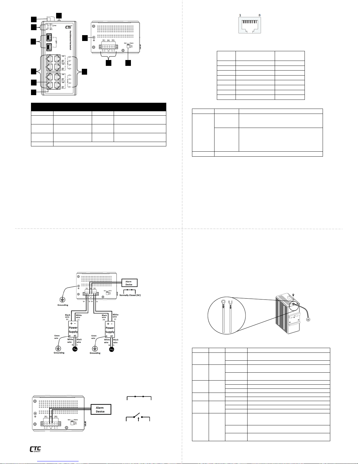
1
SFP slot 1~2
6
PoE LEDs
2
Fast Ethernet port
1~8
7
Terminal block for power
inputs & alarm relay
3
Power, SFP, Fault
LEDs
8
Grounding connection
4
Fast Ethernet
LNK/Act LED
9
DIP switch
5
Fast Ethernet 100M LED
LAN and Fiber Connection
IFS-802GS-8PH(E) PoE switches have 8 electrical LAN ports (labeled
1~8) and 2 SFP-based fiber ports (labeled SFP 1~2) on the front panel.
The LAN ports utilize shielded RJ-45 connectors that support 10/100M;
while the fiber SFP ports support 1000M.
PoE Ports
All 8 LAN ports support PoE (Power over Ethernet) per IEEE802.3af
(15.4W) or IEEE802.3at (30W) for connection to standard PoE PD
(Power Devices) such as IP Cameras, Access Points, IP Phones, Digital
Signage. Using switches with PoE function can eliminate the need to run
separate power to these devices thereby simplifying deployment and
reducing expenses.
The LAN ports may also connect to any non-PoE device for normal
Ethernet transmission without any damage to the non-PoE device or to
this device.
Recommended Power, Alarm, Grounding Wiring Scheme
DC Power Connection
A removable terminal block on the top panel provides both power
and alarm connections. Power can be provided through the dual inputs
from separate sources (PWR1 & PWR2). One power supply is enough to
power up the device. If two power supplies are used, the device
provides power redundancy function. See the figure provided below for
recommended DC power wiring scheme.
Figure 4. Recommended DC Power Connection
Alarm Relay Connection
The alarm relay contact can be wired into an alarm circuit which
senses an alarm condition when the contact is broken. The alarm relay
is normally closed when there is no alarm condition. Please note that
the alarm relay contact can only support 1A current at 24VDC. Do not
apply voltage and current that exceed these specifications.
Figure 5. Terminal Block
RJ-45 Ethernet Port Pinouts
Figure 3. RJ-45 Ethernet Port Pinouts
RJ-45 Ethernet & PoE Pin Assignments
Pin
No.
RJ-45 Ethernet
10/100Base-TX
PoE Output
1
RX+
V+ 2 RX-
V+ 3 TX+
V- 4 -
5 -
6 TX-
V- 7 -
8 -
DIP Switch
DIP No.
Function
Description
1
Alarm
Enable
Provide alarm relay and fault LED
indication if there is a power failure in
one supply.
Alarm
Disable*
Disable alarm relay and fault LED
indication if there is a power failure in
one supply. Connecting to a single power
source, place this switch ON to disable
alarm.
2
Reserved for future use.
* The default setting.
Earth Ground Connection
An earth ground connector is provided on the top panel with an earth
ground sign next to it. Grounding the device can help to release leakage
of electricity to the earth safely so as to reduce injuries from
electromagnetic interference (EMI).
Prior to connecting to the power, it is important to connect the
ground wire to the earth. Follow steps below to install ground wire:
1. Loosen or remove the grounding screw.
2. Attach the grounding screw to the ring-type or fork-type terminal
of the grounding cable. Make sure that the grounding cable is long
enough to reach the earth.
3. Use a screwdriver to fasten the grounding screw.
Figure 7. Grounding Cable Type Figure 8. Grounding Connection
LED Indicators
LED
Color
Status
Definition
PWR1
PWR2
Green
On
Power is connected and active at the
PWR1/PWR2 input terminal connection.
Off
PWR1/PWR2 is not connected.
Fault
Amber
On
One of the power inputs has fault condition
(Alarm DIP switch must be enabled).
Off
Normal operation without faults.
Alarm DIP switch is disabled.
LAN
LNK/
ACT
Green
On
Ethernet link is up.
Blinking
Blinking when there is Ethernet traffic.
Off
No Ethernet link.
100M
Yellow
On
The connected LAN speed is 100M.
Off
LAN speed is 10M.
SFP1
SFP2
Green
On
The fiber SFP link is up.
Blinking
Blinking when there is data traffic.
Off
No fiber link.
PoE
Green
On
The respective LAN port has successfully
negotiated PoE and is supplying output
power to the remote connected PD.
Blinking
One of the PoE faults (overload, short circuit,
port failure at startup) occurs.
Off
PD is not connected or output power is not
provided.
- 6 -
1 2 3 4 7 8 7 9 6 8 5
Figure 1. Front Panel
Figure 2. Top Panel
- 3 -
- 5 -
Figure 6. Alarm
Relay Circuit
- 4 -
Normally Closed
(NC)
Fault
Ring-type
terminal
Fork-type
terminal
www.ctcu.com
 Loading...