

Page 1
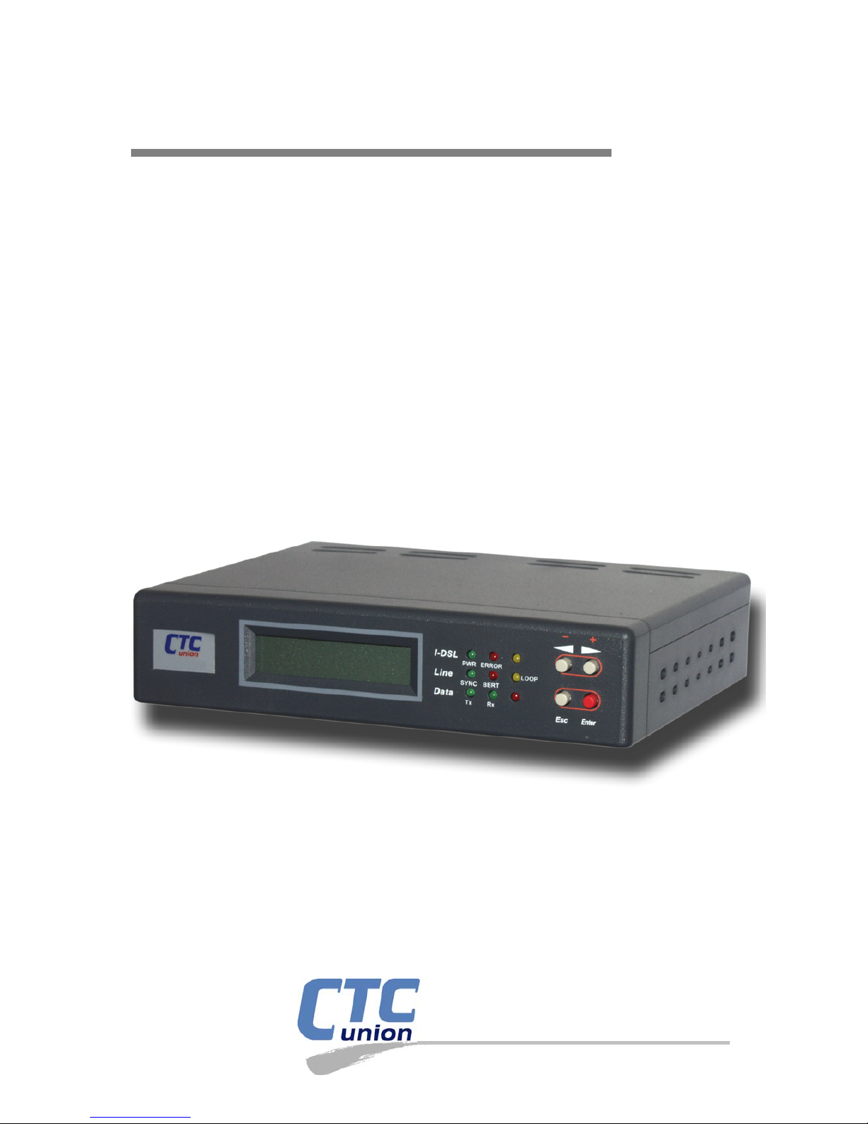
USER MANUAL
I-DSL64
Single / Port Leased Line Modem
G.703 64K Co-Directional I/F
CTC Union Technologies Co., Ltd.
Page 2

Page 3

The information in this publication has been carefully checked and is believed to be entirely accurate at the
time of publication. CTC Union Technologies assumes no responsibility, however, for possible errors or omissions, or
for any consequen ces resulting from the u s e of the informa tion contained herein . C TC Union Technologies res erves the
right to make changes in its products or product specifications with the intent to improve function or design at any time
and without notice and is not required to update this documentation to reflect such changes.
CTC Union Technologies makes no warranty, representation, or guarantee regarding the suitability of its
products for any particular purpose, nor does CTC Union assume any liability arising out of the application or use of
any product and specifically disclaims any and all liability, including without limitation any consequential or incidental
damages.
CTC Union products are not designed, intended, or authorized for use in systems or applications intended to
support or sustain life, or for any other application in which the failure of the product could create a situation where
personal injury or death may occur. Should the Buyer purchase or use a CTC Union product for any such unintended or
unauthorized application, the Buyer shall indemnify and hold CTC Union Technologies and its officers, employees,
subsidiaries, affiliates, and distributors harmless against all claims, costs, damages, expenses, and reasonable attorney
fees aris ing out of, either direct ly or indirectly, any claim of pe rsonal in jury or d eath th at may be associ ated with such
unintended or unauthorized use, even if such claim alleges that CTC Union Technologies was negligent regarding the
desi gn or manufa c ture of s aid product.
TRADEMARKS
Microsoft is a registered tra demark of Microsoft Corp.
HyperT er minal™ i s a reg istered tr ademark of Hilg raeve Inc.
WARNING:
This equipment has been tested and found to comply with the limits for a Class A digital device, pursuant to
Part 15 of the FCC Rules. Th es e limits are designed to provide r easonable protection against harmful int erference wh en
the equipment is operated in a commercial environm en t. This equi pment gener ates, uses, and can radi ate radio
frequency energ y and if not installed an d us ed in accordance wit h the instr u ction manual may cause harmful
inter ference in which case the user will be r eq u ired to correct the interference at his own expense. NOTI CE : (1) The
changes or modifica tions not ex pressivel y ap p roved by the party responsible for com p liance cou l d void the user's
auth or ity to opera te the equipm ent. (2) Shielded int er fa ce cables and AC power cor d, if any, must be u sed in order to
comply with the emission limits.
CISPR PUB.22 Class A COMPLIANCE:
This devi ce compli es with EMC directive of the European Comm unity and m eets or exceeds t he following
technical standard. EN 55022 - Limits and Methods of Measurement of Radio Interference Characteristics of
Information Technology Equipment. This device complies with CISPR Class A.
WARNING:
This is a Class A product. In a domestic environment this product may cause radio interference in which case
the user may be required to take adequate measures.
CE NOTICE
Markin g by the symbol CE in d icates compliance of this equipm en t to the EMC directive of th e European
Community. Such mar k in g is indicat ive that this equipment meets or ex ceed s the following technical stand ards: EN
55022:1994/A1:1995/A2:1997 Class A and EN61000-3-2:1995, EN61000-3-3:1995 and EN50082-1:1997
Page 4

CTC Union Technologies Co. , Ltd.
Far Eastern Vienna Technology Center (Neihu Technology Park)
8F, No. 60, Zhouzi St.
Neihu, Ta ip ei, 114
Taiwan
Phone: +886-2-2659-1021
FAX: +886-2-2799-1355
I-DSL64
Single/Port Leased Line Modem.
G.703 64K Co-Directional I/F
User Manual
Version 1.1 September 2005 Released for first printing
This manual supports the following models:
I-DSL64
This document is the first official release manual. Please check CTC Union's website for any updated manual
or contact us by E-mail at [email protected]. Please address any comments for improving this manual or to point out
omis sion s or err ors to marketi ng@ctcu. c om. Thank you.
The inform ation containe d in this document may be updated at any time without notice.
Page 5

Table of Contents
i
1 Introduction to the I-DSL64 …………………………. 1
1.1 General Overview ………………………………………. 1
1.2 Applications for I-DSL64 ……………………………….. 2
1.3 Hardware Overview …………………………………….. 3
1.4 Factory Default Setup for the I-DSL64 ………………. 7
2 Installation ……………………………………………… 7
3 Configuration …………………………………………. 9
3.1 LT/NT ……………………………………………………… 10
3.2 Data Rate ………………………………………………….. 11
3.3 Clock Mode ……………………………………………….. 12
3.4 Restart Device …………………………………………….. 13
3.5 Load Default Settings ……………………………………. 14
4 Maintenance ……………………………………………. 15
4.1 Show Status ……………………………………………….. 16
4.2 Local Loopback …………………………………………… 17
4.3 Digital Loopback ………………………………………… 19
4.4 CSU Loopback …………………………………………… 21
4.5 DSU Loopback …………………………………………… 23
4.6 2047 BERT ………………………………………………… 27
Appendix A ……………………………………………….. 30
Appendix B ……………………………………………….. 31
Page 6

Table of Contents
ii
Page 7

I-DSL64 USER’S MANUAL
1
2 Introduction to the I-DSL64
The I-DSL64 is a stand-alone data circuit-terminating equipment (DCE) unit that
connects data terminal equipment (DTE) to the digital data network (DDN). The
I-DSL64 utilizes 2B1Q line coding and echo cancellation technique for full duplex
operation at synchronous 64Kbps transmission rate over 2-wire unconditioned twisted
pair.
The I-DSL64 family consists of the following:
z Single DTE port
The I-DSL64 family provides the type of DTE interfaces as following:
z G.703 Co-Directional
1.1 General Overview
The I-DSL64 is a stand-alone leased line modem with the following features:
z Support for 64Kbps of bandwidth for high speed data applications
z One DTE port
z One LCD panel and four push buttons
z Ability to display and configure local and remote system parameters
z Three system clock sources:
Loop timing
Internal timing
External timing: From DTE interface
z Four loopback functions:
Local loopback
Digital loopback
CSU loopback
DSU loopback
z Built-in 2047 BERT pattern generator and receiver for each DTE port
z AC or DC power input (depending on model)
Page 8
I-DSL64 USER’S MANUAL
2
1.2 Applications for I-DSL64
The following sections show you the possible applications for the I-DSL64.
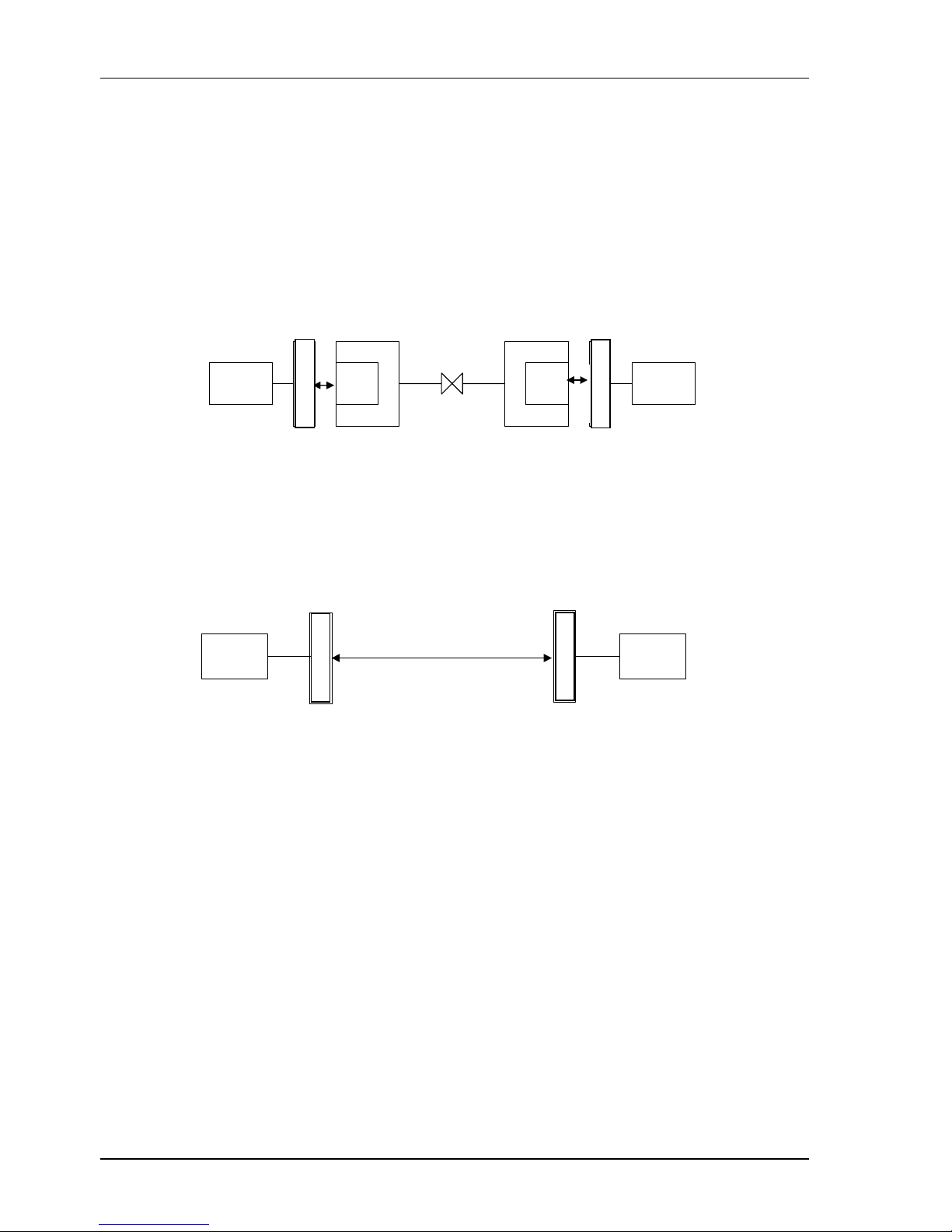
z The I-DSL64 delivers dedicated digital access to remote users when they are
connected to a central office over a PCM, Advance D4 Channel Bank (AD4),
Digital Loop Carrier (DLC) system or U loop ISDN repeater (Figure 1).
DTE DTE
DTE
NTU-128
OCU
- DP
DTE
NTU-128
OCU
- DP
T1
PCM / AD4 PCM / AD4
Figure 1 I-DSL64 connects with multiplexer system
z The I-DSL64 can serve as a 64Kbps limited distance modem for leased line
application (Figure 2).
DTE
DSL
DTE
NTU-128
NTU-128
Figure 2 I-DSL64 leased line application
I-DSL64
I
-
DSL64
I-DSL64
I-DSL64
I-DSL64
Page 9
I-DSL64 USER’S MANUAL
3
1.3 Hardware Overview
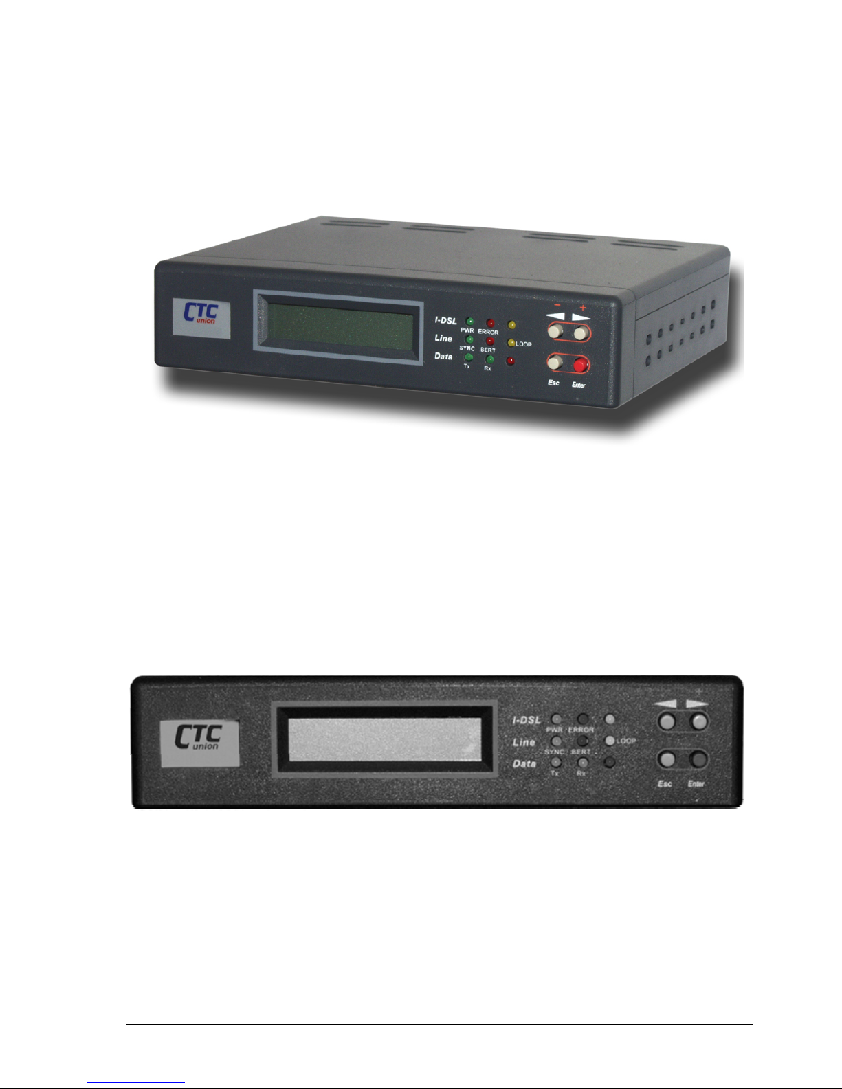
Figure 3 Overview of the I-DSL64
1.3.1 Front Panel
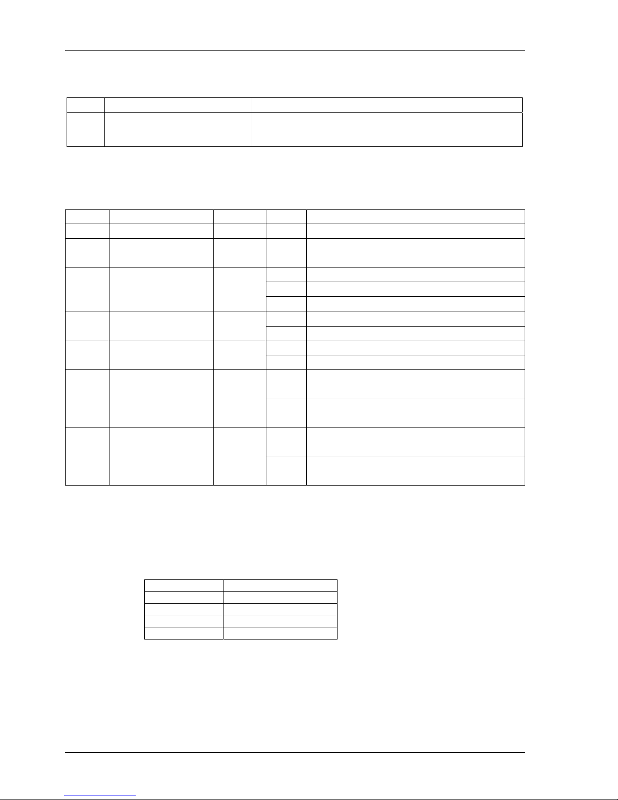
The I-DSL64's front panel (Figure 4) consists of the following:
z LCD module
z LED module
z Push button module
Figure 4 I-DSL64 front panel
Page 10
I-DSL64 USER’S MANUAL
4
1.3.1.1 LCD Display
LCD Function Note
Show status and setups 1. English display
2. Backlight
3. 16 X 2 character display
Table 1 Function of the LCD
1.3.1.2 LED Indictors for I-DSL64
LED's Function Color Status
Note
Power Power Indicator Green On Power normal
Error Bit error detection Red Off Port G64KC 2047 BERT closed or no error
detection
Off System and remote unsynchronized
On System and remote synchronized
Sync DSL Indicator Green
Blink System detect DSL side CRC error (NEBE)
Off No 2047 BERT test BERT Bit Error Rate Test Red
On 2047 BERT test
Off System functioning normally Loop Testing indicator Yellow
On System in testing mode
Off No data transmission from DTE to port
G64KC
TX Data transmitting Green
On Data transmission from DTE to port
G64KC
Off No data transmission from port G64KC to
DTE
RX Data receiving Green
On Data transmission from port DTE-A to
DTE
Table 2 Function of the LED indictors
1.3.1.3 Push Buttons
Button Function
Esc Exit
Left Arrow Left
Right Arrow Right
Enter Enter / Confirm
Table 3 Function of the LCD push button
Page 11
I-DSL64 USER’S MANUAL
5
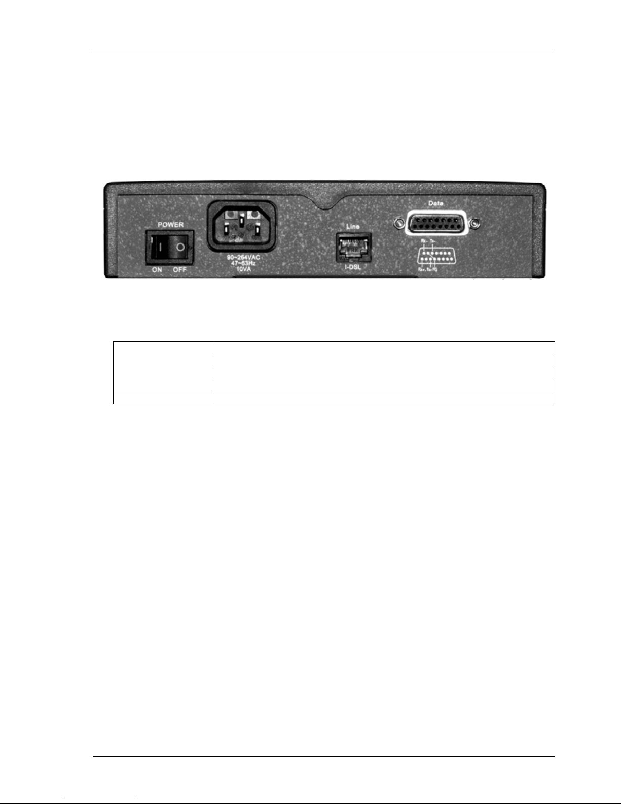
1.3.2 Rear Panel
The I-DSL64’s rear panel (Figure 5) consists of the following:
z DTE Interface
z DSL Interface
z Power Interface
Figure 5 The I-DSL64 rear panel
Each interface has the following functions:
Label Function
POWER Power switch
AC-IN Power inlet:input voltage 90~264VAC / 10VA.
I-DSL 2B1Q Line interface port
Data Co-directional interface port
Table 4 Function of the rear panel
Page 12

I-DSL64 USER’S MANUAL
6
1.3.3 DTE Interface
The I-DSL64 family provides a single DTE interface as follows:
z G.703 Co-Directional (G64KC)
The DTE interface of the I-DSL64 is fixed at 64Kbps.
1.3.4 DSL Interface
1.3.4.1 DSL Characteristics
z Line coding: 2B1Q
z Type: Full duplex with adaptive echo cancellation
z Impedance: 135Ω
z Physical line type: Unconditioned twisted pair, 19-26AWG
z Conforms to ANSI T1.601-1992
1.3.4.2 DSL Connector
The I-DSL64's DSL interface provides a 2-wire RJ45 for ISDN basic rate
U-interface.
1.3.4.3 DSL Protection
There are surge protectors, current limiters and fuses for the primary
protection and zener diodes and a diode bridge for secondary protection. The
I-DSL64 conforms to FCC Part 68 Type A & B.
1.3.4.4 Sealing Current
z NT mode: The I-DSL64 provides a closed loop for sealing current. The
loop resistance is about 334Ω.
z LT mode: The I-DSL64 emulates a constant current source. It outputs a
DC current of less than 20mA with a voltage of -42V~-56VDC. The I-
DSL64 can protect itself when the DSL loop shorts or when it connects
with another current source.
Page 13
I-DSL64 USER’S MANUAL
7
1.4 Factory Default Setup for the I-DSL64
The I-DSL64 is supplied with a default setup, which is used when it is first started
up. The default configuration is as follows:
System Parameters Default Setup
DTE port (G64KC)
LT/NT NT
DATA RATE 64K
CLOCK SOURCE Loop
Table 5 System Default Setup
2 Installation
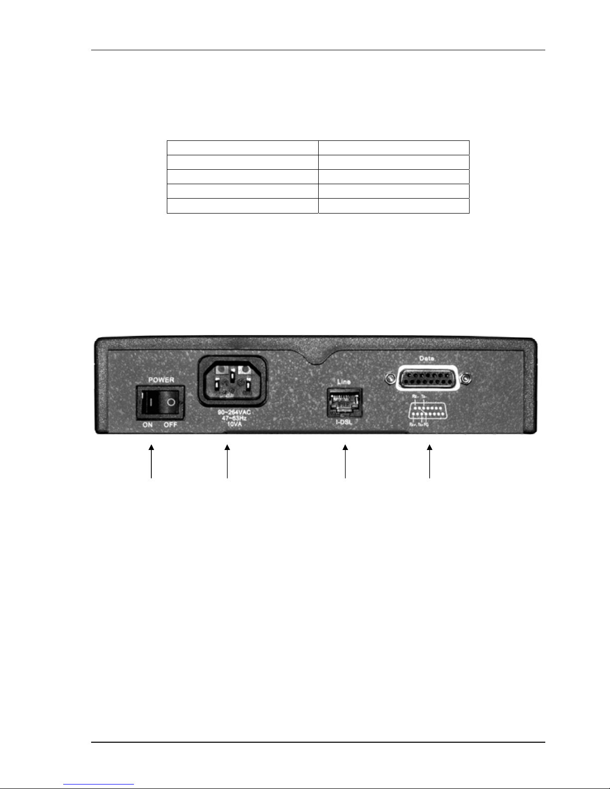
The following shows the rear panel of the I-DSL64 and the connection diagram.
Figure 6 I-DSL64 back panel connections
Power
Switch
Power
Inlet
(AC shown)
DSL Lin e
Connector
G.703
Co-directional
Line C onnector
Page 14

I-DSL64 USER’S MANUAL
8
To install the I-DSL64, proceed as follows:
Step 1 Connecting the I-DSL64 to the DSL (U interface)
Connect the DSL port labeled Line on the rear panel to the remote site.
Step 2 Connecting the G64KC (to other co-directional equipment)
Connect the DTE port labeled Data on the rear panel to the co-directional
equipment using twisted pair cable.
Step 3 Connecting the Power Adaptor to your I-DSL64
Connect the power to the port labeled AC 90~264VAC on the rear panel of your
I-DSL64.
Step 4 Turning on the power
Turn on the power switch labeled POWER on the rear panel of your I-DSL64.
The PWR LED lights up to indicate the power is normal. All the LED’s on the
front panel (except for the PWR LED) will blink for five seconds. The LCD will
show the following:
** I-DSL64 **
==========
After blinking for five seconds, the LED’s will turn off, and the I-DSL64 will
begin a self-test. The local system tries to synchronize with the remote site.
After the initial setup, you can modify the configuration by using the LCD and the four
push buttons (Left arrow, Right arrow, Esc, Enter) on the front panel.
Page 15

I-DSL64 USER’S MANUAL
9
3 Configuration
You can change the I-DSL64's configuration from the local site only. You can change
any of these 5 settings:
(1) LT/NT
(2) DATA RATE: time slot
(3) CLOCK SOURCE
(4) RESTART DEVICE
(5) LOAD DEFAULT SETTING
Note 1: Item (3) only shows up in the LT mode.
While setting up the items (1)~(2), the LCD will indicate current system settings by a
”->” sign. If the user needs to change the settings, just use (Left arrow) or (Right
arrow) to move the cursor (blinking) to the preferred option, then press (Enter) to
confirm the operation. After this, the ”->” sign will point to the new setting and
indicate the device configuration has been change successfully.
The user may press (Esc) to leave any operating screen. If there are any settings
changed before you leave the current screen, the system will remind user to save the
changes. The screen displays this message:
* SAVE SETUP *
NO YES
If you choose YES, the settings will be saved in system.
If you choose NO or press (Esc), the settings will not be saved in system.
Page 16
I-DSL64 USER’S MANUAL
10
3.1 LT/NT
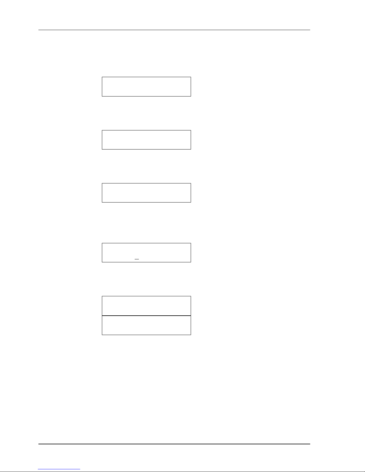
Step 1 Enter ”DEVICE CONFIGURATION” screen, then press (Enter)
DEVICE
CONFIGURATION
Step 2 Use (Left arrow) or (Right arrow) to choose ”CHANGE SETUP”,
then press (Enter) .
CHANGE
SETUP
Step 3 Use (Left arrow) or (Right arrow) to choose ”LT/NT” screen,
then press (Enter) .
*CHANGE SETUP*
LT/NT
Step 4 Use (Left arrow) or (Right arrow) to choose ”LT” or “NT”, then
press (Enter) .
* LT/NT *
LT NT
Step 5 The LCD will show one of the following messages to indicate
successful completion.
* LT/NT *
LT MODE
* LT/NT *
NT MODE
Page 17
I-DSL64 USER’S MANUAL
11
3.2 Data Rate
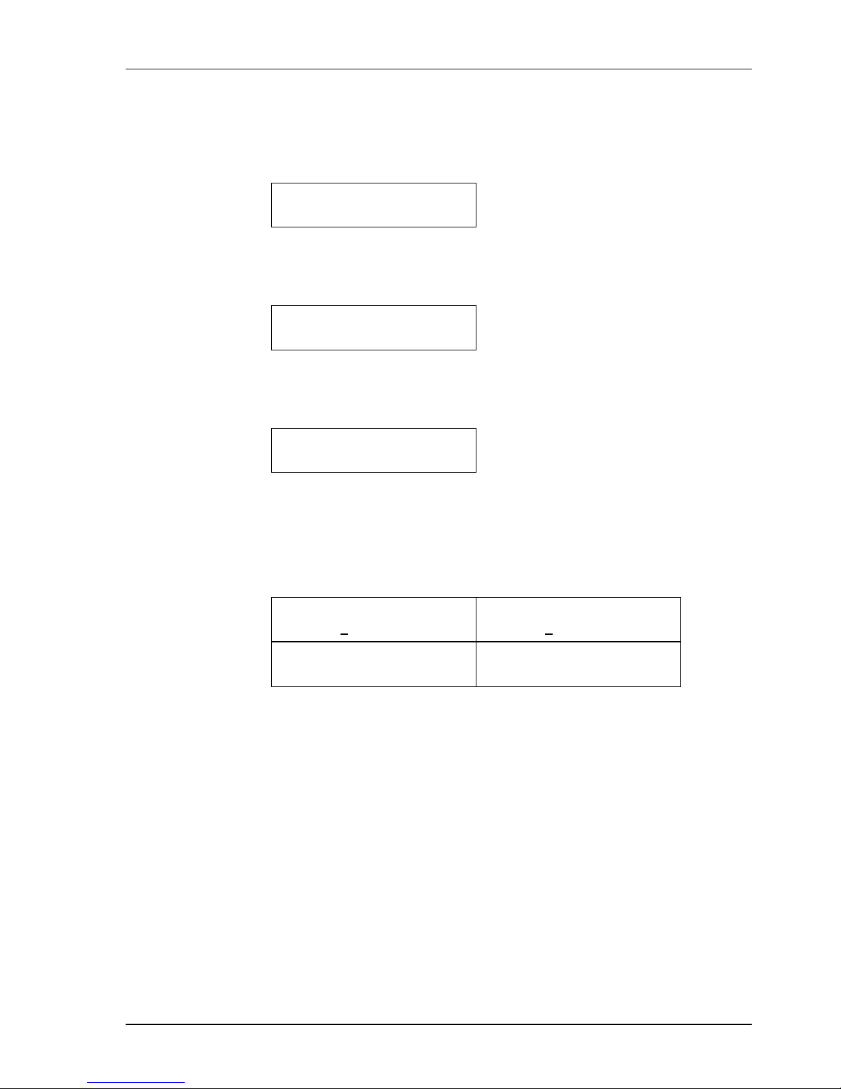
Step 1 Enter ”DEVICE CONFIGURATION” screen, then press (Enter)
DEVICE
CONFIGURATION
Step 2 Use (Left arrow) or (Right arrow) to choose ”CHANGE SETUP”,
then press (Enter) .
CHANGE
SETUP
Step 3 Use (Left arrow) or (Right arrow) to choose ”DATA RATE”, then
press (Enter) .
*CHANGE SETUP*
DATA RATE
note: G.703 64K co-directional must have fixed data rate of 64Kbps. The timeslot may
be selected as either B1 or B2 channel and must match on both local and remote units.
Step 4 Use (Left arrow) or (Right arrow) to choose the G64kC time slot
(B1 or B2), then press (Enter) .
* G64KC*
64K ( B1 )
* G64KC *
64K ( B2 )
* G64KC *
OFF
Page 18

I-DSL64 USER’S MANUAL
12
3.3 Clock Mode
The I-DSL64 provides three options for system clock sources:
Loop timing
Internal timing
External timing: From Data interface (G64KC)
Note 1: Clock mode can only be configured when the system in the LT mode.
Note 2: When the system in the LT mode, it can be configured only as internal or external
timing.(G64KC)
Note 3: When the system in the NT mode, loop timing is fixed.
Step 1 Enter ”DEVICE CONFIGURATION” screen, then press (Enter)
DEVICE
CONFIGURATION
Step 2 Use (Left arrow) or (Right arrow) to choose ”CHANGE SETUP”,
then press (Enter) .
CHANGE
SETUP
Step 3 Use (Left arrow) or (Right arrow) to choose ”CLOCK SOURCE”
screen, then press (Enter) .
*CHANGE SETUP*
CLOCK SOURCE
Step 4 Use (Left arrow) or (Right arrow) to choose ”INT” for internal
timing or G64KC for external timing, then press (Enter) .
* CLOCK SOURCE *
INT G64KC
Step 5 The LCD will show one of the following messages to indicate
successful completion.
* CLOCK SOURCE *
INTERNAL
* CLOCK SOURCE *
FROM G64KC
Page 19
I-DSL64 USER’S MANUAL
13
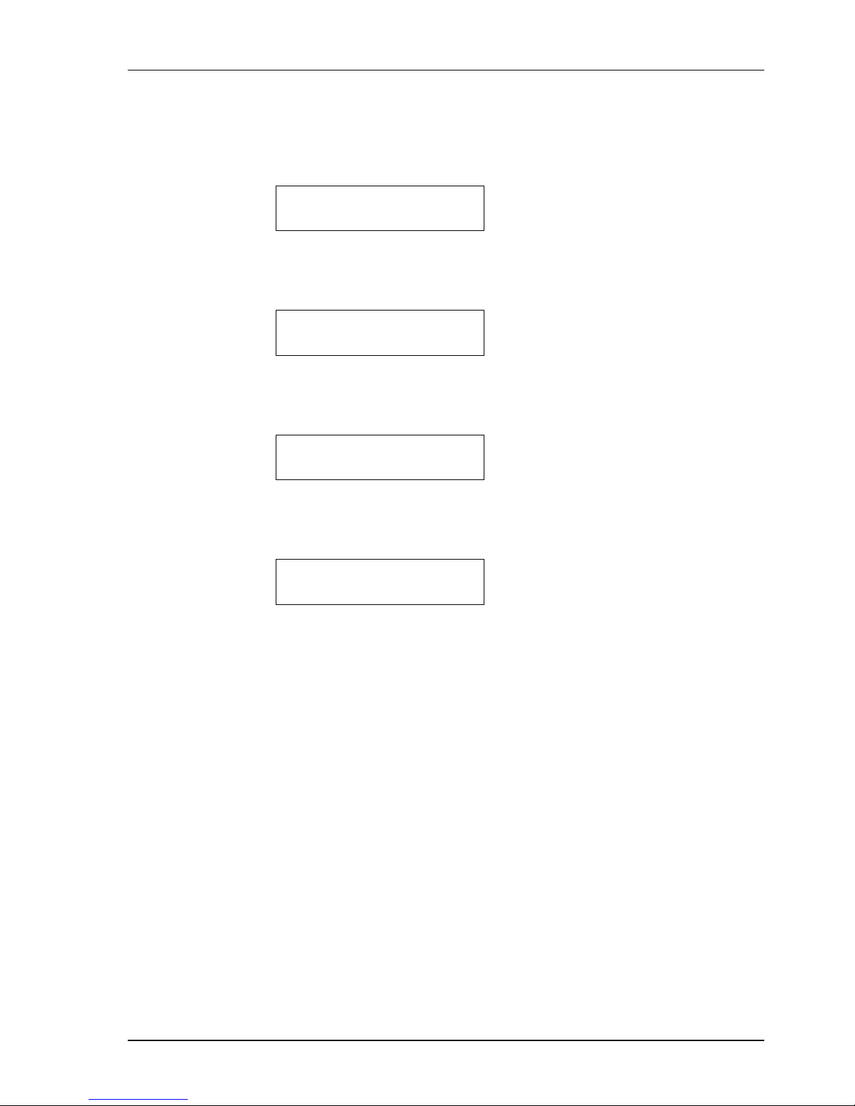
3.4 Restart Device
Step 1 Enter ”DEVICE CONFIGURATION” screen, then press (Enter)
DEVICE
CONFIGURATION
Step 2 Use (Left arrow) or (Right arrow) to choose ”RESTART
DEVICE”, then press (Enter) .
RESTART
DEVICE
Step 3 Use (Left arrow) or (Right arrow) to choose “YES”, then press
(Enter) .
*RESTART DEVICE*
NO YES
Step 4 The LCD will show the following message and the I-DSL64
will
restart after 3 seconds.
RESTART DEVICE
AFTER 3 SECONDS
Page 20

I-DSL64 USER’S MANUAL
14
3.5 Load Default Settings
For factory default settings, please refer to Table 5.
Step 1 Enter ”DEVICE CONFIGURATION” screen, then press (Enter)
DEVICE
CONFIGURATION
Step 2 Use (Left arrow) or (Right arrow) to choose ”LOAD DEFAULT
SETTINGS”, then press (Enter) .
LOAD
DEFAULT SETTINGS
Step 3 Use (Left arrow) or (Right arrow) to choose “YES”, then press
(Enter) .
*LOAD DEFAULT*
NO YES
Step 4 The LCD will display the following message and the I-DSL64
will load default settings from EEROM and restart after 3
seconds.
LOAD DEFAULT
& RESTART DEVICE
Page 21

I-DSL64 USER’S MANUAL
15
4 Maintenance
The I-DSL64 provides a user-friendly interface. The user can utilize the LCD and four
push buttons (Left arrow, Right arrow, Esc, Enter) on the front panel to view system
status (local).
The I-DSL64 provides four kinds of loopback and one built-in BERT function. These can
be used to maintain, diagnose and test system and loop performance without any other
equipment. The following screens can be displayed.
z Show Status
z Local Loopback
z Digital Loopback
z CSU Loopback
z DSU Loopback
z BERT G64KC (2047)
Note 1: The CSU and DSU loopbacks will work properly under the DSL environment with a
10
-3
bit error rate.
Note 2: The Digital, CSU and DSU loopbacks could be activated only when the DSL is
synchronized.
Note 3: The system will release the Digital, CSU and DSU loopbacks when the DSL is out-of-
sync.
4.1 Show Status
The I-DSL64 can display system status of the local or remote site. 18 items are
available:
z LT/NT mode
z Data Port Number
z Clock mode
z G64KC speed
z Local loopback
z Digital loopback
z CSU loopback
z DSU Loopback (G64KC)
z BERT G64KC
Page 22
I-DSL64 USER’S MANUAL
16
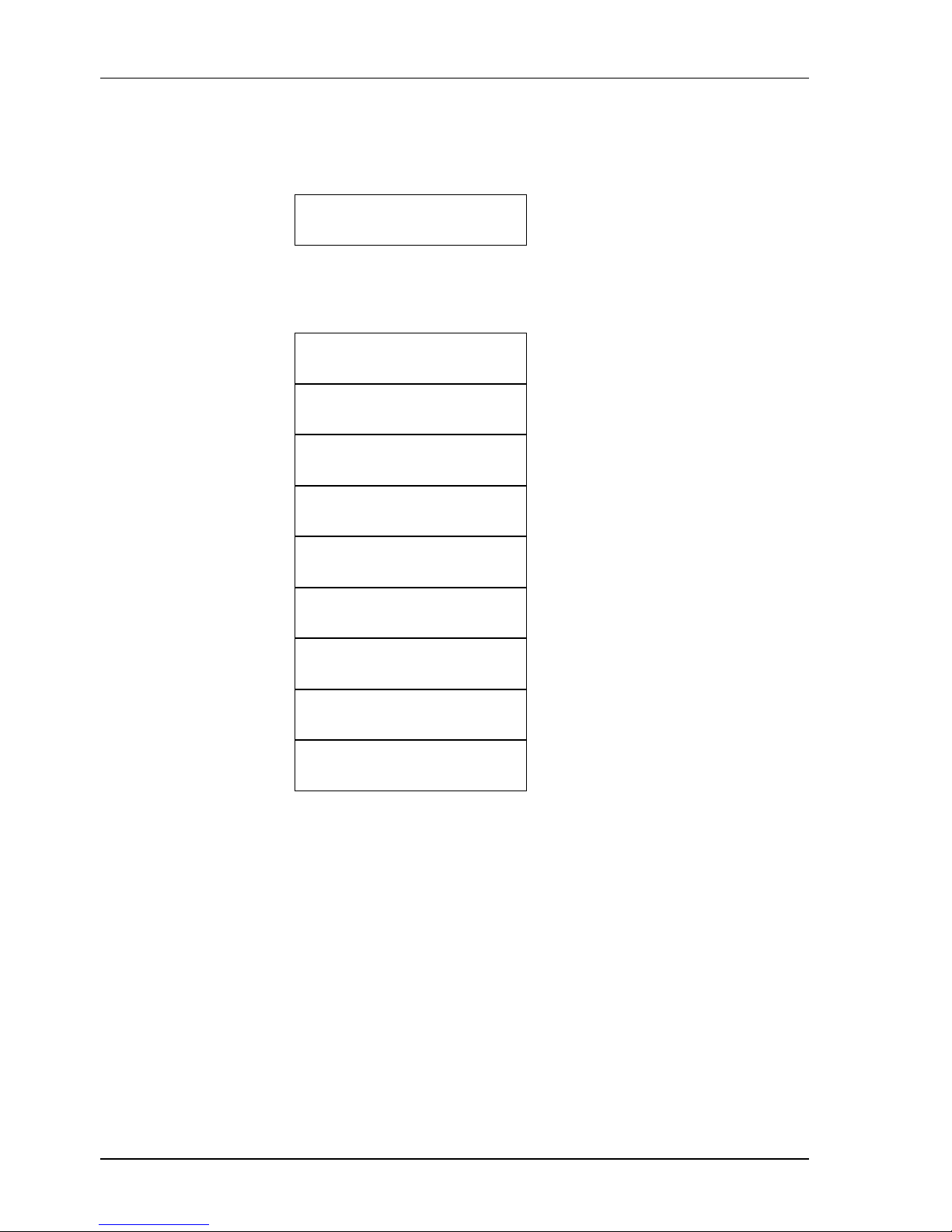
4.1.1 To View System Status
Step 1 Enter ”SHOW STATUS” screen, then press (Enter)
SHOW
STATUS
Step 2 Use (Left arrow) or (Right arrow) to check the system current
status.
* MODE *
XX
* PORT NUMBER *
XX
* CLOCK MODE *
XXXXXX
* G64KC SPEED *
XXXXXX
* LOCAL LOOPBACK *
XXXXXX
* DIGITAL LOOPBACK *
XXXXXX
* CSU LOOPBACK *
XXXXXX
* DSU LOOP G64KC *
XXXXXX
* BERT G64KC *
XXXXXX
Page 23
I-DSL64 USER’S MANUAL
17
4.2 Local Loopback
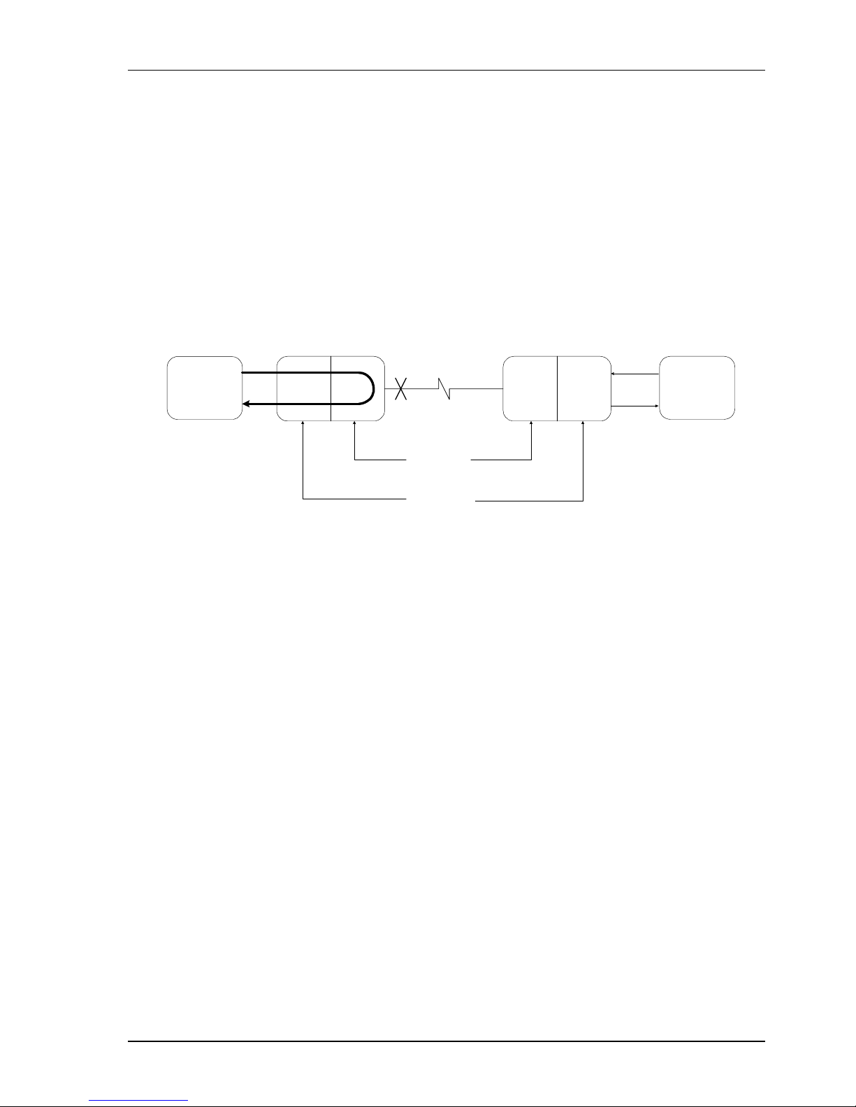
When the local loopback is activated, it will utilize the local site of the I-DSL64 (see
Figure 7). This will test the transmitting/receiving functions of the local site. During
this test, the remote unit will lose DSL synchronization. When the local loopback test
is released, the system will restart and return to its initial state. During the local
loopback testing period, the TST and ACT LED’s will be lit.
Figure 7 Local Loopback
TD
RD
DTE
Local Site
NTU-128
TD
RD
DTE
Line Interface
Digital Interface
Remote Site
NTU-128
Local
Loopback
I-DSL64
I-DSL64
Page 24
I-DSL64 USER’S MANUAL
18
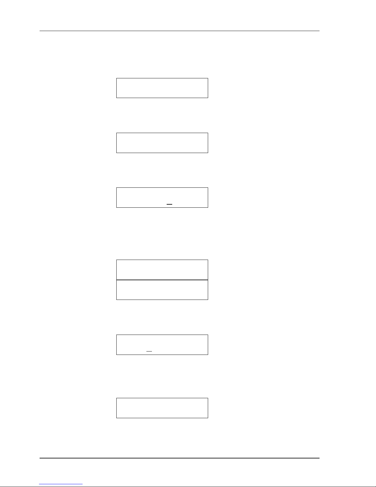
4.2.1 To Execute Local Loopback
Step 1 Enter ”DEVICE DIAGNOSTIC” screen, then press (Enter)
DEVICE
DIAGNOSTIC
Step 2 Use (Left arrow) or (Right arrow) to choose “LOCAL
LOOPBACK”, then press (Enter) .
LOCAL
LOOPBACK
Step 3 Use (Left arrow) or (Right arrow) to choose “ON”, then press
(Enter) .
* LOCAL LOOP *
OFF ON
Step 4 The local loopback is executed successfully when the LCD
shows ”-- LOCAL LOOP — OK !!” and both the SYNC and Loop
LED’s are lit. Otherwise, it shows ”-- LOCAL LOOP -FAILED !!”, meaning the local loopback was not activated.
-- LOCAL LOOP --
OK !!
-- LOCAL LOOP --
FAILED !!
Step 5 Use (Left arrow) or (Right arrow) to choose “OFF”, then
p
ress
(Enter) .
* LOCAL LOOP *
O
FF ON
Step 6 When the local loopback has been released successfully, the LCD
shows “ -- LOCAL LOOP -- RELEASE OK !! ”. The Loop LED is
turned off and the system returns to initial state.
-- LOCAL LOOP --
RELEASE OK !!
Page 25
I-DSL64 USER’S MANUAL
19
4.3 Digital Loopback
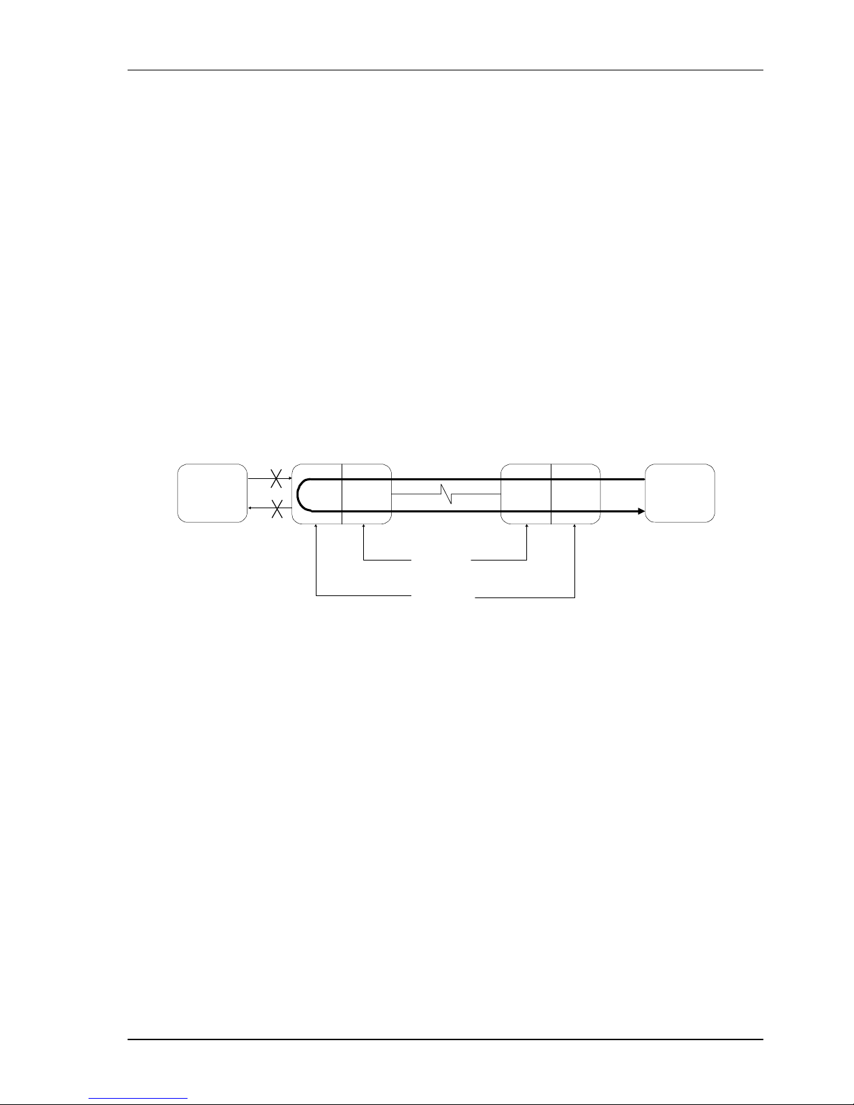
When the digital loopback is activated, it will test the
transmitting/receiving functions of the I-DSL64 when using a DSL condition. The
digital loopback function is only executable when the DSL connection is
synchronized with the remote site. When this test is executed, all the payloads (B1
and B2 Channels) are looped and the Loop LED is lit and the DTE ports are turned
off.
Note: When the digital loopback is activated, all the DSL payloads (B1 and B2 Channels) are
occupied into a testing mode. So, CSU, DSU loopback and 2047 BERT are disabled in the
local site.
Figure 8 Digital Loopback
TD
RD
DTE
Local Site
NTU-128
TD
RD
DTE
Line Interface
Digital Interface
Remote Site
NTU-128
Digital
Loopback
I-DSL64
I-DSL64
Page 26
I-DSL64 USER’S MANUAL
20
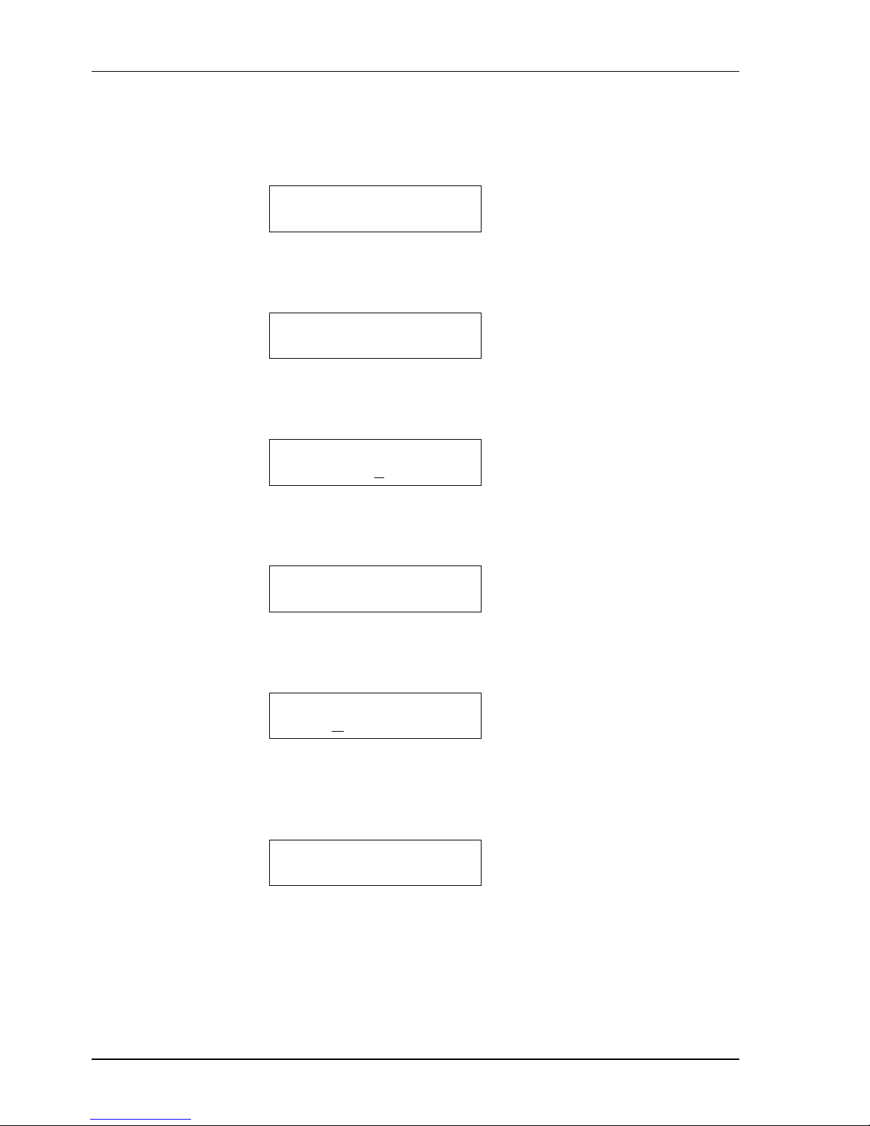
4.3.1 To Execute Digital Loopback
Step 1 Enter ”DEVICE DIAGNOSTIC” screen, then press (Enter).
DEVICE
DIAGNOSTIC
Step 2 Use (Left arrow) or (Right arrow)
to choose “DIGITAL
LOOPBACK”, then press (Enter) .
DIGITAL
LOOPBACK
Step 3 Use (Left arrow) or (Right arrow) to choose “B1+B2”, then press
(Enter) .
* DIGITAL LOOP *
OFF B1+B2
Step 4 Digital loopback is executed successfully when LCD shows
”--DIGITAL LOOP — B1+B2 !!” and the Loop LED is lit.
-- DIGITAL LOOP --
B1+B2 OK !!
Step 5 Use (Left arrow) or (Right arrow) to choose “OFF”, then press
(Enter) .
* DIGITAL LOOP *
O
FF B1+B2
Step 6 When the digital loopback has been released successfully, the
LCD shows “ -- DIGITAL LOOP -- RELEASE OK !! ”. The Loop
LED is turned off.
-- DIGITAL LOOP --
RELEASE OK !!
Page 27
I-DSL64 USER’S MANUAL
21
4.4 CSU Loopback
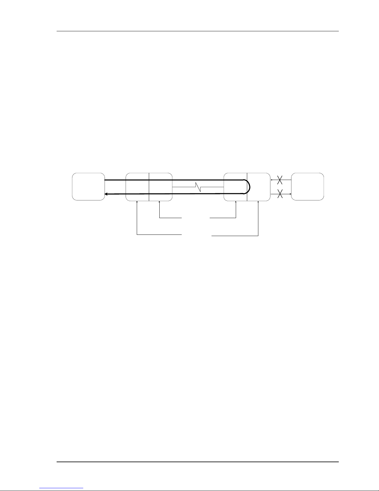
The CSU loopback is a testing function controlled from the unit in the LT mode. The
LT unit (the local site in Figure 9) sends loopback messages through an EOC,
specified by ANSI T1.601, and the NT unit (the remote site in Figure 9) executes the
loopback function when it receives a valid loopback command. The loopback tests
the local and remote units and the DSL. This procedure may be performed without
using other personnel. (The digital loopback requires two or more people).
Figure 9 CSU Loopback
4.4.1 LT Mode
There are four kinds of EOC loopback messages that can be chosen :
z Return To Normal (RTN): 1111 1111
z Operate B1-Channel Loopback: 0101 0001
z Operate B2-Channel Loopback: 0101 0010
z Operate 2B+D Loopback: 0101 0000
When you specify the eoc loopback message, it is sent continuously with the
address ”000”. When one of the “operate” messages activates the CSU loopback,
the TST LED will be turned on. It will be turned off when the RTN message is
sent.
Note: When the CSU loopback is activated, the assigned DSL payloads (B1, B2 Channels
or 2B+D) are occupied in a testing mode, so the digital loopback and DSU loopback of the
corresponding DTE ports are disabled at the local site.
TD
RD
DTE
Local Site (LT)
NTU-128
TD
RD
DTE
Line Interface
Digital Interface
Remote Site (NT)
NTU-128
eoc CSU
Loopback
B1 or B2 or 2B+D
I-DSL64 I-DSL64
Page 28

I-DSL64 USER’S MANUAL
22
4.4.2 NT Mode
There are two modes available for the user:
z AUTO: Automatically detect EOC messages from the LT and execute the
corresponding activation or release of CSU loopback.
z OFF: Ignore EOC messages from the LT.
Note 1: When the CSU loopback is activated, the assigned DSL payloads (B1, B2
Channels or 2B+D) are occupied in a testing mode, so the DSU loopback of the
corresponding DTE ports and 2047 BERT are disabled at the local site.
Note 2: If the I-DSL64 is set to “OFF”, the system will release all the CSU loopbacks.
When the CSU loopback is activated, the Loop LED will be turned on. It will be
turned off when the unit receives a valid RTN command.
All CSU replies (loopbacks) from the NT will be latching, permitting multiple
EOC loopback messages to be in effect simultaneously. When the NT receives the
RTN message, all the CSU loopbacks are released.
Page 29
I-DSL64 USER’S MANUAL
23
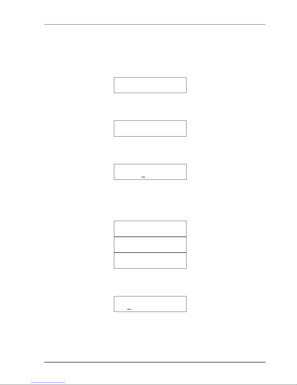
4.4.3 To Execute CSU Loopback
4.4.3.1 LT Mode
Step 1 Enter ”DEVICE DIAGNOSTIC” screen, then press (Enter)
DEVICE
DIAGNOSTIC
Step 2 Use (Left arrow) or (Right arrow) to choose “CSU
LOOPBACK”, then press (Enter) .
CSU
LOOPBACK
Step 3 Use (Left arrow) or (Right arrow) to choose “B1”, “B2” or
“2B+D”, then press (Enter) .
* CSU LOOP *
RTN B1 B2 2B+D
Step 4 The CSU loopback is executed successfully when the LCD
shows ”-- CSU LOOP — REMOTE B1 OK!!”, ”-- CSU
LOOP — REMOTE B2 OK!!” or ”-- CSU LOOP —
REMOTE 2B+D !!” and the Loop LED is turned on.
-- CSU LOOP --
REMOTE B1 OK !!
-- CSU LOOP --
REMOTE B2 OK !!
-- CSU LOOP --
REMOTE 2B+D OK !!
Step 5 Use (Left arrow) or (Right arrow) to choose “RTN”, then
press (Enter) .
* CSU LOOP *
RTN B1 B2 2B+D
Step 6 When the LCD shows “ -- CSU LOOP – REMOTE RTN
OK !! ”, the CSU loopback has been released. The Loop LED
is then turned off.
Page 30
I-DSL64 USER’S MANUAL
24
-- CSU LOOP --
REMOTE RTN OK !!
4.4.3.2 NT Mode
Step 1 Enter ”DEVICE DIAGNOSTIC” screen, then press (Enter)
DEVICE
DIAGNOSTIC
Step 2 Use (Left arrow) or (Right arrow) to choose “CSU
LOOPBACK”, then press (Enter) .
CSU
LOOPBACK
Step 3 Use (Left arrow) or (Right arrow) to choose “AUTO” or
“OFF”, then press (Enter) .
* CSU LOOP *
AUTO OFF
4.5 DSU Loopback
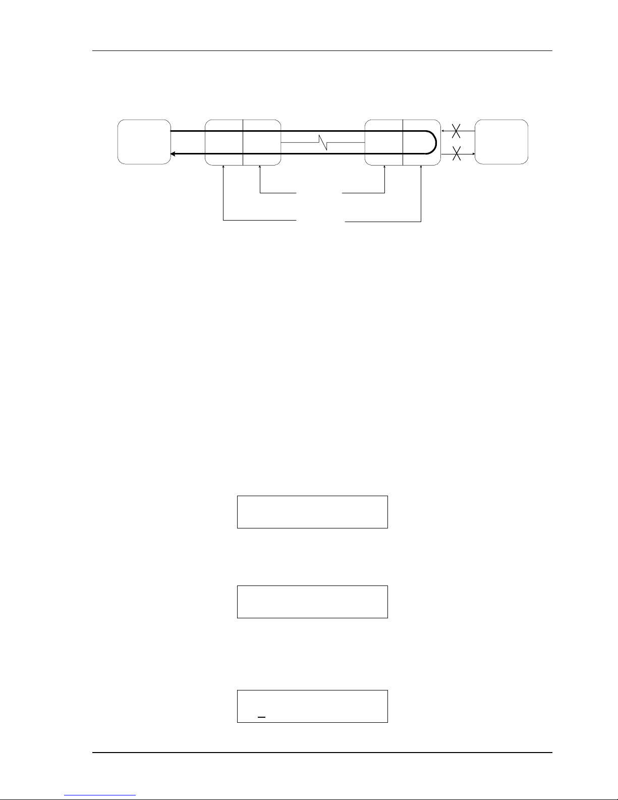
When you initiate the DSU loopback test, the transmitting unit will send a loopback
message, specified by ITU-T V.54, to the receiving unit. Either the local or remote site
can initiate the test. When the receiving unit receives a valid loopback message from
the transmitting unit, it will send back an acknowledgement message and execute a
DSU loopback. This tests the B1, B2 or B1+B2 channel, as well as the condition of the
DSL.
When the DSU loopback is activated, the Loop LED will be turned on. It will be
turned off when a valid release pattern is received.
Page 31
I-DSL64 USER’S MANUAL
25
Figure 10 DSU Loopback
There are four modes can be chosen by the user:
z DISABLE: Ignore ITU-T V.54 pattern from remote.
z ENABLE: Detect ITU-T V.54 pattern from the remote site and execute the
corresponding activation or release of DSU loopback automatically.
z REQ REMOTE LOOP: Send ITU-T V.54 loopback pattern to the remote site to
activate remote DSU loopback.
z REQ REM RELEASE: Send ITU-T V.54 release pattern to remote site, to release
remote DSU loopback.
4.5.1 To Execute DSU Loopback
4.5.1.1 Request Remote Loopback and Release
Step 1 Enter ”DEVICE DIAGNOSTIC” screen, then press (Enter)
DEVICE
DIAGNOSTIC
Step 2 Use (Left arrow) or (Right arrow) to choose “DSU
LOOPBACK V.54 (G64KC))”, then press (Enter) .
DSU LOOPBACK
V.54(G64KC)
Step 3 Use (Left arrow) or (Right arrow) to choose “REQ REMOTE
LOOP” for request for remote CSU loopback, then press
(Enter) .
DSU LOOP (G64KC)
R
EQ REMOTE LOOP
TD
RD
DTE
Local Site
NTU-128
TD
RD
DTE
Line Interface
Digital Interface
Remote Site
NTU-128
V.54 DSU
Loopback
DTE-A
or
DTE-B
DTE-A
or
DTE-B
I-DSL64
I-DSL64
Page 32
I-DSL64 USER’S MANUAL
26
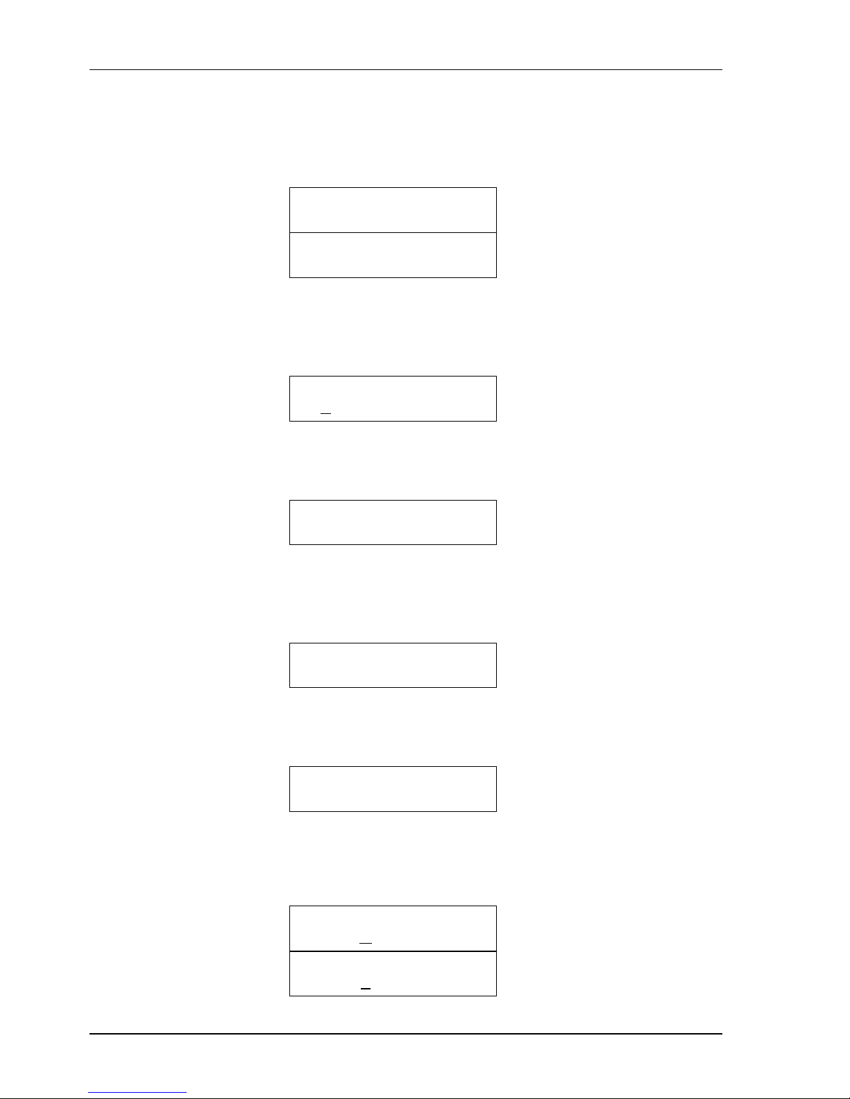
Step 4 The DSU loopback is executed successfully when the LCD
shows ”REQUEST OK!!” and the Loop LED is turned on.
Otherwise, the LCD shows “REQUEST FAIL!!” and the Loop
LED is off.
DSU LOOP (G64KC)
REQUEST OK!!
DSU LOOP (G64KC)
REQUEST FAIL!!
Step 5 Use (Left arrow) or (Right arrow) to choose “REQ REM
RELEASE” to request the remote CSU loopback release, then
press (Enter) .
DSU LOOP (G64KC)
REQ REM RELEASE
Step 6 When the DSU loopback has been released successfully, the
LCD shows “REQ REM RELEASE” and Loop LED is off.
DSU LOOP (G64KC)
REM LOOP RELEASE
4.5.1.2 Disable and Enable DSU Loopback Function
Step 1 Enter ”DEVICE DIAGNOSTIC” screen, then press (Enter)
DEVICE
DIAGNOSTIC
Step 2 Use (Left arrow) or (Right arrow) to choose “DSU
LOOPBACK V.54 (G64KC)”, then press (Enter) .
DSU LOOPBACK
V.54(G64KC)
Step 3 Use (Left arrow) or (Right arrow) to choose “DISABLE” for
disabling CSU loopback function or “ENABLE” for enablin
g
CSU loopback function, then press (Enter) .
DSU LOOP (G64KC)
DISABLE
DSU LOOP (G64KC)
ENABLE
Page 33
I-DSL64 USER’S MANUAL
27
4.6 2047 BERT
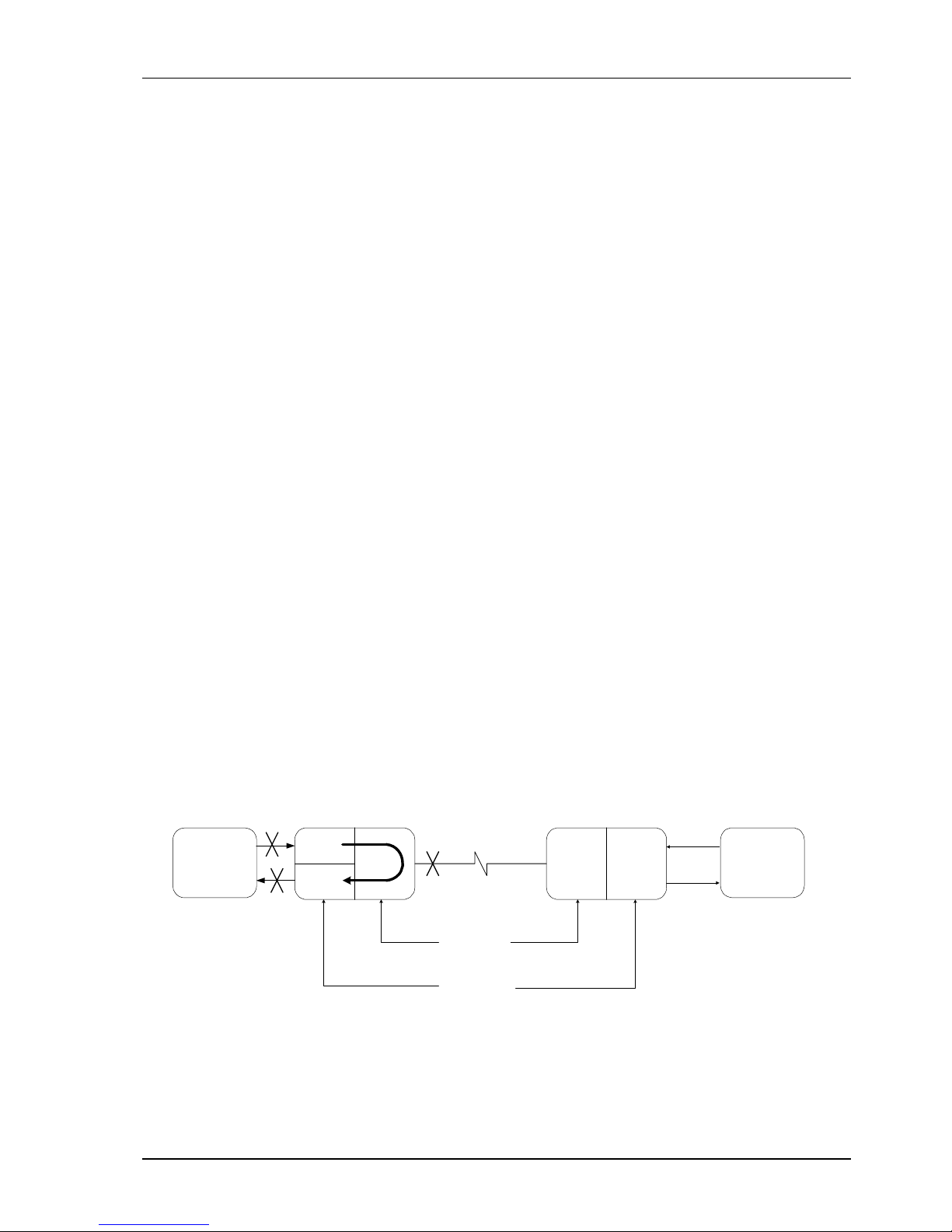
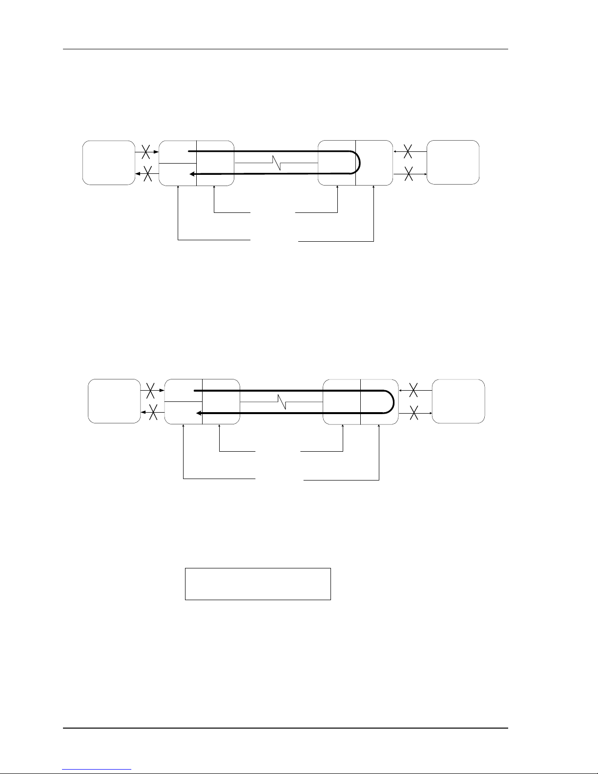
There is one built-in 2047 BERT test pattern generator and receiver in each DTE port
of the I-DSL64. You can easily use the testing mechanism and other loopback
functions to check the status of system itself, the DSL and the remote equipment
(Figure 11,12,13).
Note: The 2047 BERT function is not available under the following conditions.
z Time slot you wish to use occupied by Digital Loopback test.
z Time slot you wish to use occupied by CSU loopback test initiated from remote
site.
z DTE port you wish to use occupied by DSU loopback test initiated from remote
site.
When 2047 BERT function is activated, the BERT LED is turned on, the assigned DTE
port off and the timer activated. Users may check the RUN TIME and BIT ERR
results on the LCD.
z RUN TIME: The elapsed time with range from 0 to 65535 seconds. If results are
out of this range, a ”+” sign appears to the left of the digits.
z BIT ERR: The error bit count with range from 0 to 65535 bits. If results are out of
this range, a ”+” sign appears to the left of the digits. For each bit error, the
counter will add one and the ERR LED will blink. If the bit errors are too
numerous to synchronize the 2047 BERT pattern, or there is no data input, the
BIT ERR will display “NO SYNC” and the bit error counter will stop counting.
Figure 11 Local Loopback & 2047 BERT
TD
RD
DTE
Local Site
NTU-128
TD
RD
DTE
Line Interface
Digital Interface
Remote Site
NTU-128
Local
Loopback
&
2047 BERT
2047 GEN
2047 RCV
I-DSL64 I-DSL64
Page 34
I-DSL64 USER’S MANUAL
28
Figure 12 CSU Loopback & 2047 BERT
Figure 13 DSU Loopback & 2047 BERT
4.6.1 To Execute 2047 BERT
Step 1 Enter ”DEVICE DIAGNOSTIC” screen, then press (Enter)
DEVICE
DIAGNOSTIC
Step 2 Use (Left arrow) or (Right arrow)
to choose “BERT 2047
( G64KC )” , then press (Enter) .
TD
RD
DTE
Line Interface
Digital Interface
Remote Site (NT)
NTU-128
eoc CSU
Loopback
&
2047 BERT
B1 or B2 or 2B+D
TD
RD
DTE
Local Site (LT)
NTU-128
2047 GEN
2047 RCV
I-DSL64
I-DSL64
TD
RD
DTE
Line Interface
Digital Interface
Remote Site
NTU-128
V.54 DSU
Loopback
&
2047 BERT
DTE-A
or
DTE-B
DTE-A
or
DTE-B
TD
RD
DTE
Local Site
NTU-128
2047 GEN
2047 RCV
I-DSL64 I-DSL64
Page 35
I-DSL64 USER’S MANUAL
29
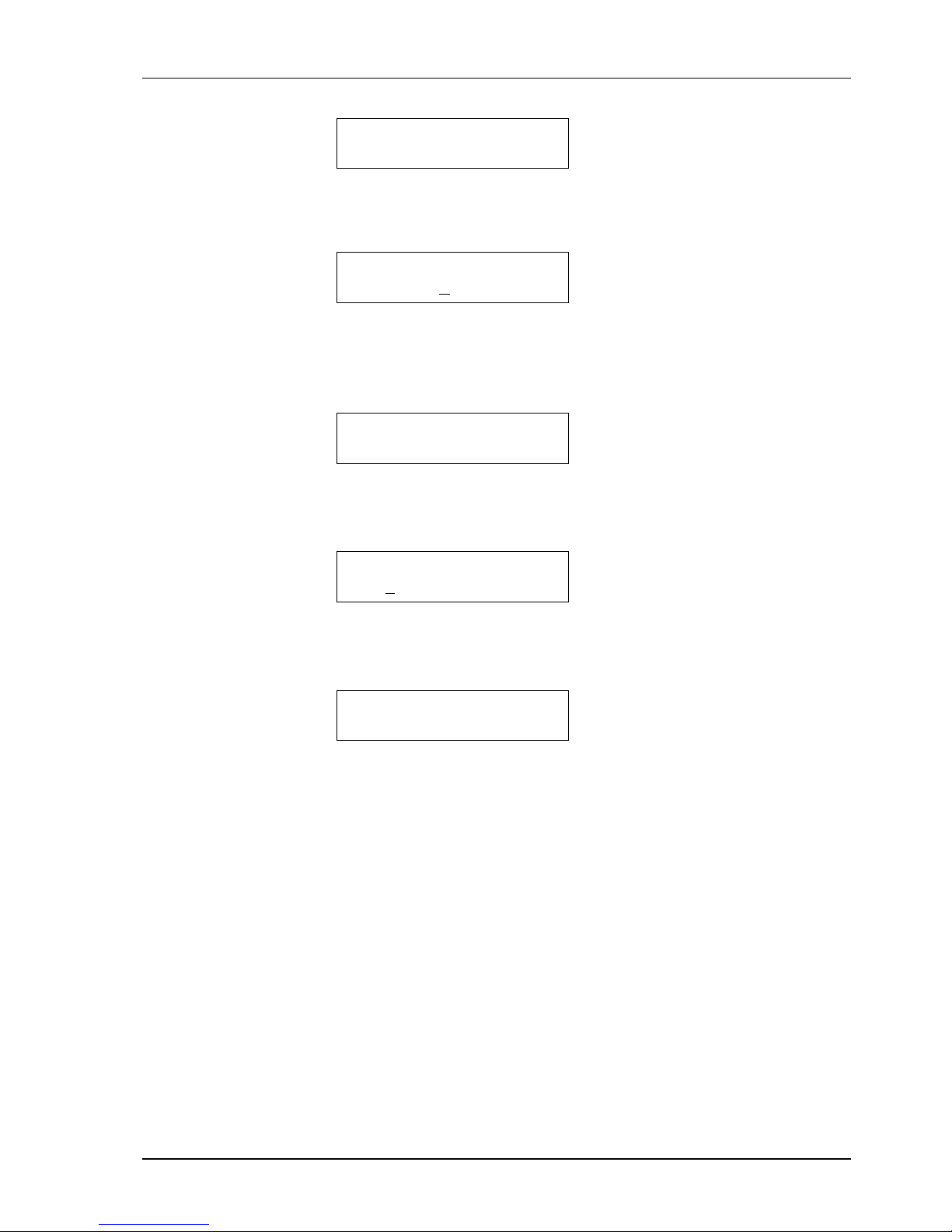
BERT 2047
( G64KC)
Step 3 Use (Left arrow) or (Right arrow) to choose “RUN”, then press
(Enter) .
BERT 2047(G64KC)
STOP RUN RST
Step 4 The 2047 BERT has executed successfully when the LCD shows
as below. The RUN (SEC) counter should be increasing and the
BERT LED should be on.
RUN(SEC) : XXXXX
BIT ERR : XXXXX
Step 5 Use (Left arrow) or (Right arrow) to choose “STOP” to sto
p
counting or “RST” to reset counter, then press (Enter) .
BERT 2047(G64KC)
STOP RUN RST
Step 6 IF you choose “STOP”, the counters will stop. If you choose
“RST”, the counters will reset to zero and begin counting again.
RUN(SEC) : XXXXX
BIT ERR : XXXXX
Page 36
I-DSL64 USER’S MANUAL
30
Appendix A
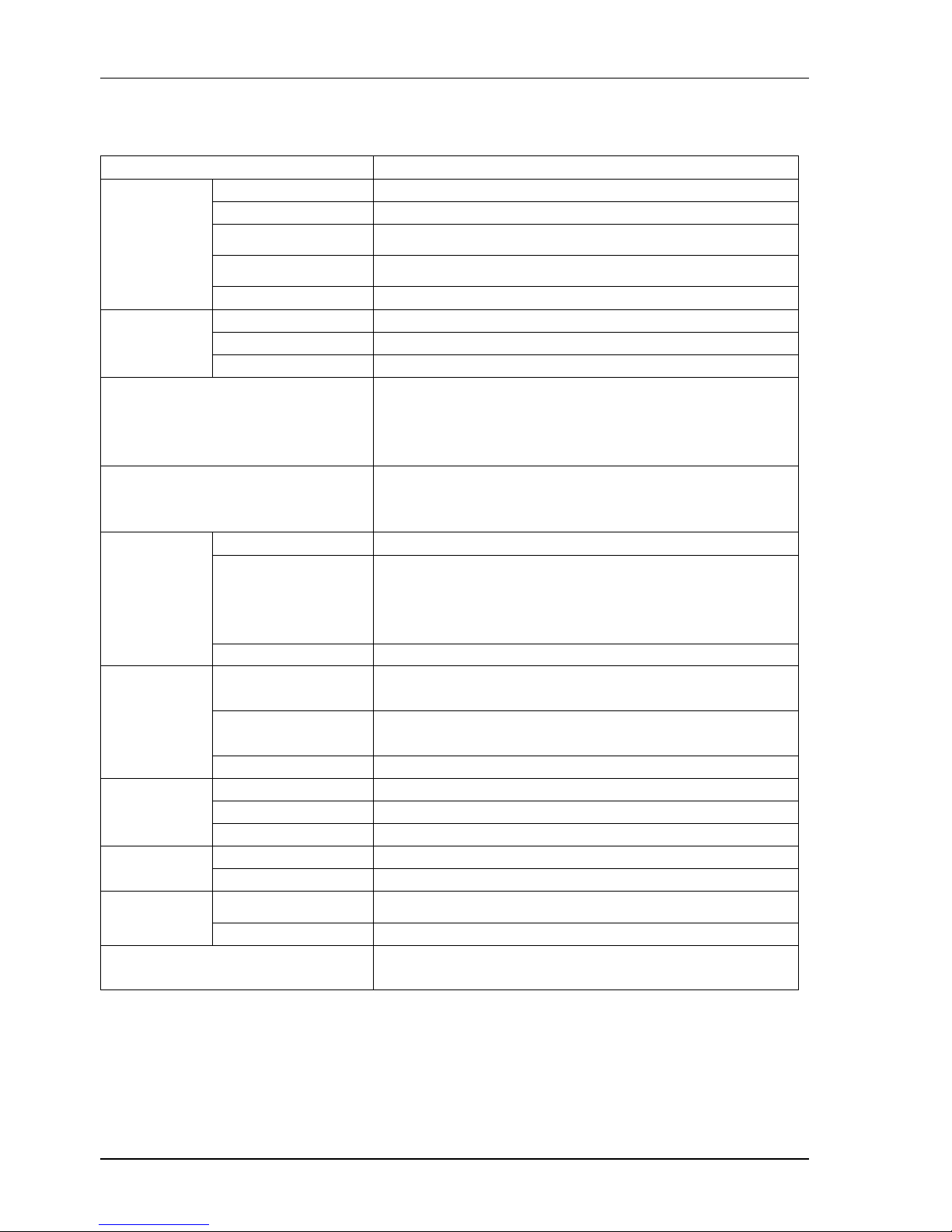
Specifications:
Items Notes
Type Full duplex with adaptive echo cancellation
Line coding 2B1Q
Line Type
Unconditioned twisted pair, 19-26 AWG
Surge Protection
Meets FCC Part 68 Type A,B
Network
Line
Interface
Connector RJ45
Number of Ports 1
Data Rate Synchronous : 64Kbps
DTE
Interface
Connector G.703 64K Co-Directional 4-wire twisted pair
Operation Range
2-wire mode
Up to 5.5Km over 26 AWG
Up to 7.0Km over 24 AWG
Meet ANSI T1.601 and ETSI ETR 080 standard loop
Clock Source
Internal
Line
G64KC
eoc Fully detect EOC message defined by ANSI T1.601
Loopbacks
Local loopback
Digital loopback
ITU-T V.54 DTE loopback
ANSI T1.601 CSU loopback
Diagnostic
2047 BERT DTE-(G64KC)
Keypad
4 operation keys ( Esc, Left arrow, Right arrow,
Enter)
LED
7 status LED’s
PWR, SYNC, Loop, BERT, Data[Tx, Rx, ERR]
Front Panel
LCD 16 X 2 with backlight
AC Input 90~264VAC, 47~63Hz
DC Input 18~60VDC
Power
Consumption >10VA
Dimensions 19.5X4.8X16.8 cm (W X H X D)
Physical
Mounting Desk-top stackable
Temperature
0~50℃
Environment
Humidity 0%~95%RH (non-condensing)
EMI
Meets IEC CISPR22 Class A
Meets FCC Part 15 Subpart B Class A
Page 37
I-DSL64 USER’S MANUAL
31
Appendix B
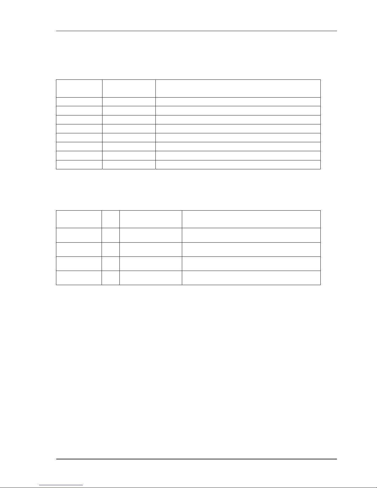
DSL Connector and Pin Designations
PIN
NUMBER
FUNCTION NOTES
1 No Connection Reserved for future standardization
2 No Connection Reserved for future standardization
3 No Connection Reserved for future standardization
4 Signal Tip or ring of pair to and from the network interface
5 Signal Tip or ring of pair to and from the network interface
6 No Connection Reserved for future standardization
7 No Connection Reserved for future standardization
8 No Connection Reserved for future standardization
Data Connector and Pin Designations
Signal
Function
Pin Direction Description
Protective
Ground
4
10
Chassis Ground
May be isolated from Signal Ground.
Signal
Ground
8 Common Signal Ground.
Transmitted
Data
3
11
To I-DSL64 Serial Co-directional data from
DTE.
Received
Data
1
9
Fm I-DSL64 Serial Co-directional data at the
output of the I-DSL64 receiver.
Page 38

Page 39

Page 40

Transmission Units
CTC Union Technologies Co., Ltd.
Far Eastern Vienna Tec hnology Center
(Neihu Technology Park)
8F, No.60, Zhouzi Str eet
Neihu, Taipei, Taiwan
Phone:(886) 2.2659. 1021 Fax:(886) 2.2799.1355
E-mail: [email protected]
http://www.ctcu.com
 Loading...