

Page 1
Version 1.01
2006/01
CTC Union Technologies Co., Ltd.
USER MANUAL
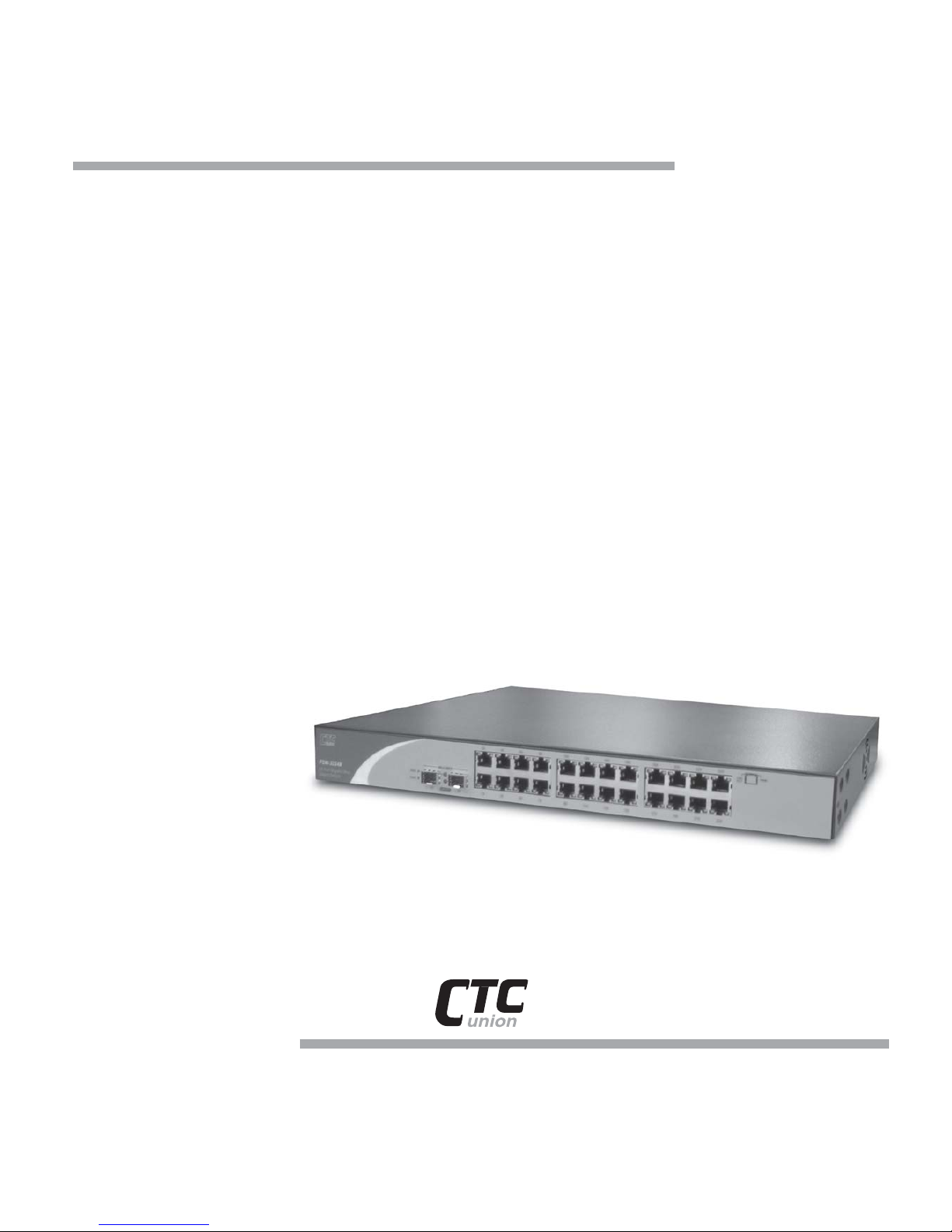
FSW3224
24 + 2G
Web Smart Switch
Page 2

24+2G Web Smart-switch User Manual
Revision 1.0- 2
1. GETTING START.............................................................................................................................................7
1.1 CONNECTING TO THE SWITCH CONSOLE PORT.....................................................................7
1.2 PC COM PORT SETTING ............................................................................................................7
1.3 CONNECTING TO THE SWITCH WEB PORT..............................................................................7
1.3.1 Advantage of Web Smart Switch..................................................................................8
2. OPERATION NOTICE..............................................................................................................................9
2.1. CONSOLE FUNCTION KEYS .........................................................................................................9
2.2. CONSOLE ACTION ITEM...............................................................................................................9
3. LOGIN..........................................................................................................................................................10
3.1. POWER-ON SELF TESTING........................................................................................................10
3.2. CONSOLE LOGIN .........................................................................................................................10
3.3. WEB LOGIN..................................................................................................................................11
3.3.1. Setting IP Address by Console Port..........................................................................11
3.3.2. Login with a Web Brower........................................................................................... 12
4. CONSOLE USER INTERFACE...........................................................................................................12
4.1. MAIN MENU ...................................................................................................................................12
4.2. PORT STATUS ................................................................................................................................14
4.3. PORT CONFIGURATION..............................................................................................................14
4.4. TRUNK CONFIGURATION...........................................................................................................15
4.5. VLAN CONFIGURATION............................................................................................................16
4.5.1. VLAN Mode: Port-based VLAN................................................................................ 17
4.5.2. Port-based VLAN Group <Add>/<Edit>Menu .................................................... 18
4.5.3. VLAN Mode: 802.IQ VLAN....................................................................................... 19
4.5.4. 802.IQ VLAN Group <Add>/ <Edit> Menu ......................................................... 19
4.5.5. Advanced 802.1Q VLAN Configuration.................................................................. 20
4.6. PORT MONITORING CONFIGURATION....................................................................................20
4.7. QOS CONFIGURATION...............................................................................................................21
4.8. BANDWIDTH CONTROL..............................................................................................................21
4.9. MISC OPERATION........................................................................................................................22
4.9.1. Advanced Switch Configuration ............................................................................... 23
4.9.2. Password Setting......................................................................................................... 24
4.9.3. Restore System Default Setting ................................................................................. 24
4.9.4. Reboot System.............................................................................................................. 24
4.9.5. System Information..................................................................................................... 25
4.9.6. Update Firmware........................................................................................................ 25
Page 3

24+2G Web Smart-switch User Manual
Revision 1.0- 3
4.9.7. IP Configuration......................................................................................................... 26
5. WEB USER INTERFACE......................................................................................................................27
5.1. WELCOME PAGE..........................................................................................................................27
5.2. MAIN MENU..................................................................................................................................27
5.3. PORT STATUS ................................................................................................................................27
5.4. PORT CONFIGURATION..............................................................................................................28
5.5. TRUNK CONFIGURATION...........................................................................................................29
5.6. VLAN CONFIGURATION............................................................................................................30
5.6.1. VLAN Mode: Port-based VLAN................................................................................ 31
5.6.2. Port-based VLAN Group <Add> / <Edit> Menu................................................. 31
5.6.3. VLAN Mode: 802.1Q VLAN ...................................................................................... 32
5.6.4. 802.1Q VLAN Group <Add> / <Edit> Menu........................................................ 32
5.6.5. Advanced 802.1Q VLAN Configuration.................................................................. 33
5.7. QOS CONFIGURATION...............................................................................................................35
5.8. BANDWIDTH CONTROL..............................................................................................................35
5.9. MISC OPERATION........................................................................................................................36
5.9.1. Advanced Switch Configuration ............................................................................... 37
5.9.2. Password Setting......................................................................................................... 37
5.9.3. Restore System Default Setting ................................................................................. 38
5.9.4. Reboot System.............................................................................................................. 38
5.9.5. IP Configuration......................................................................................................... 39
5.10. LOGOUT...................................................................................................................................39
APPENDIX A........................................................................................................................................................ 40
Page 4

24+2G Web Smart-switch User Manual
Revision 1.0- 4
1. Introduction
24+2G SMART is a high performance switch that provides users with 24
10/100Mbps Ethernet and 2 1000Mbps Gigabit ports. The Gigabit module, which can
be copper or fiber media, supports 1000BASE-SX, 1000BASE-LX or 1000BASE-T,
allowing users to increase their network response time at gigabit speeds and with
great flexibility. A RS-232 serial port provides an easy way for installation and
initial set-up.
Non-blocking and maximum wire speed performances are designed on all ports. The
Switch not only supports Auto-Negotiation, but also Auto-MDIX function on all
switched 24 10/100M RJ-45 ports and two Gigabit Copper ports in both half or full
duplex mode. The Auto-MDIX function makes it convenient for the user, because it
eliminates cabling issues.
The Switch also supports both port-based VLAN and Tag-based. To increase
bandwidth application, it supports 7 groups with up to 4 ports Trunk, and moreover,
these trunk ports provide fair-over function to provide back up when one or more
ports malfunction.
Totally front access design and full LED status display ease user’s installation and
inspection and maintenance efforts at rackmount environments. The extra LED
display reflecting the fan status allows for quick diagnosis of over-heat issues.
1.1. Unpacking
Open the shipping carton of the Switch and carefully unpack its contents, the carton
should contain the following items:
l One 24+2G, 24 port Fast Ethernet Smart Switch.
l Mounting Kit: 2 mounting brackets and screws
l Four rubber feet with adhesive backing.
l One AC power cord.
l One RS-232 cable
l This Quick Installation Guide and CD.
Page 5

24+2G Web Smart-switch User Manual
Revision 1.0- 5
1.2. Installation
Follow the guidelines below to install the Switch.
l Do not place any object weighted more than 3Kg (6.6 lb) on the Switch.
l Connect the power cord to the Switch and the power outlet.
l Leave at least 10 cm (4 inches) of space around the Switch for heat dissipation.
Desktop or Shelf Installation:
When installing the Switch on the desktop o r shelf, please attach the rubber feet to the
Switch. Peel off the protective paper on the pads and attach them on the bottom of the
Switch (one at each corner).
Rack Installation:
The 24+2G Switch is rack-mountable and you can install the Switch on an EIA-19
inch equipment rack. To do this, first install the mounting brackets on the Switch’s
side panels (one on each side), secure them with the included screws, and then use the
screws provided with the equipment rack to mount the Switch on the rack.
Power On the Switch:
The 24+2G Switch has a universal power supply and you can power up the Switch
with 90 ~ 260V AC, 50 ~ 60Hz power source. The AC power cord connector is
located at the rear of the unit and the On/Off switch is next to the connector. Connect
the power cord from the power outlet to the Switch and push the On/Off Switch to
“ON” position to power on the Switch. After the Switch is powered on, it will
perform “self-diagnostic” (POSD). This process takes about 20 seconds to complete,
during this process, the “DIAG” LED will blink green and the Switch will not
response to any configuration program and all the connections to the Switch will not
be available. When the processed is completed, the “DIAG” LED will stay solid
green.
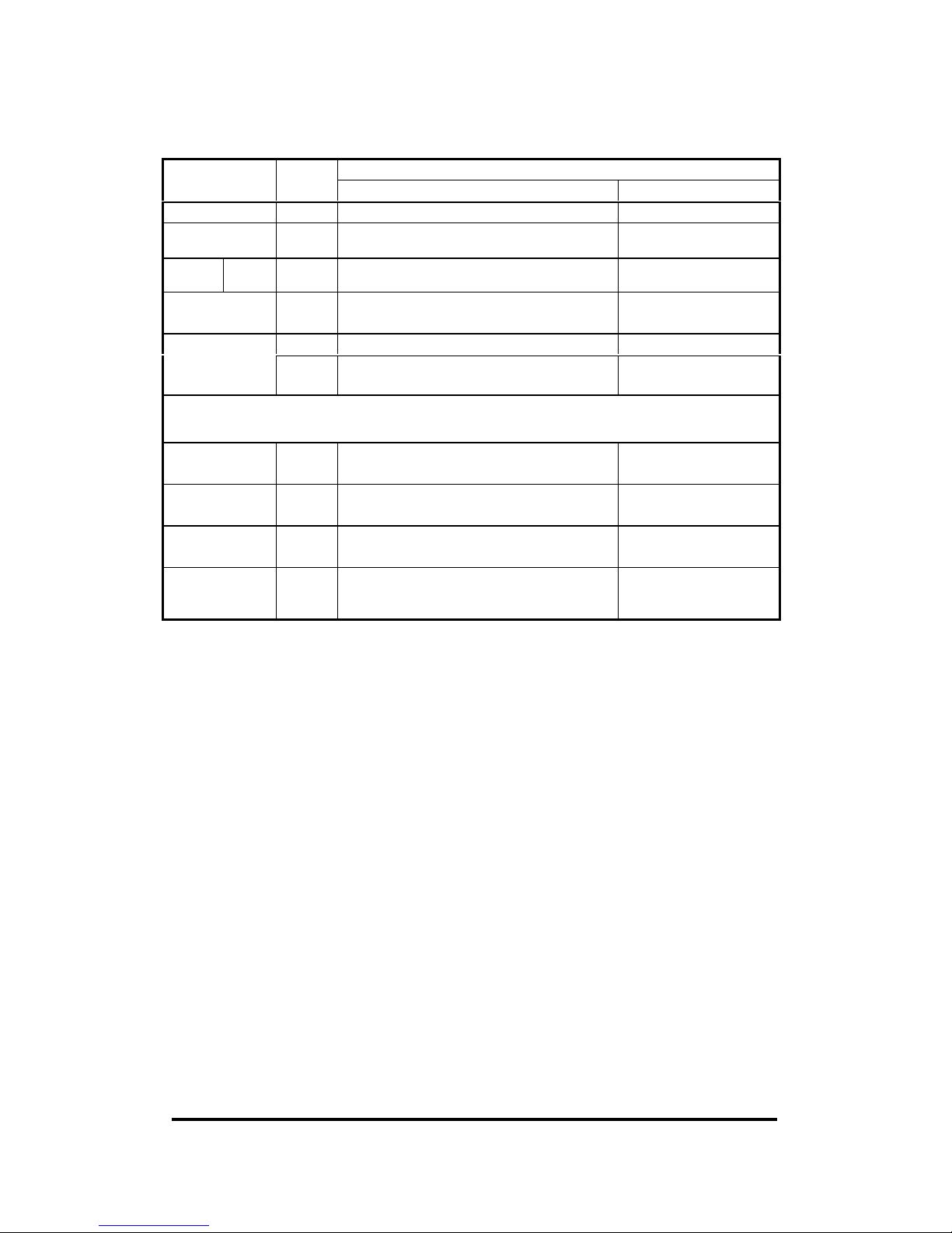
Below is a table that describes the meaning of each LED indicator.
Page 6
24+2G Web Smart-switch User Manual
Revision 1.0- 6
LED indicators information
Status
LED
Color
Solid Blinking
Power Green Power is applied to this device N/A
DIAG Green Self diagnostic successful
Performing self diagnostic
(after Power On)
Cooling
Fans
FAN Red Left cooling fan failed
N/A
LINK/ACT
(1 ~24 port)
Green
10Mbps Ethernet connection speed
TX/RX activity or
Collision
Green
100Mbps Fast Ethernet connection speed
N/A
100M
(1 ~24 port)
Off 10Mbps connection speed N/A
10/100/1000Mbps Copper Gigabit Port (Optional Module)
Top LED Orange 100Mbps Fast Ethernet connection
speed (with Middle LED off)
N/A
Middle LED Green 10Mbps Ethernet connection.
(with Top LED off)
N/A
Bottom LED Green
N/A
TX/RX activity or
collision
Top+Middle
LEDs
Orange
+ Green
1000Mbps Gigabit connection speed N/A
Page 7
24+2G Web Smart-switch User Manual
Revision 1.0- 7
2. Getting Start
2.1. Connecting to the Switch Console Port
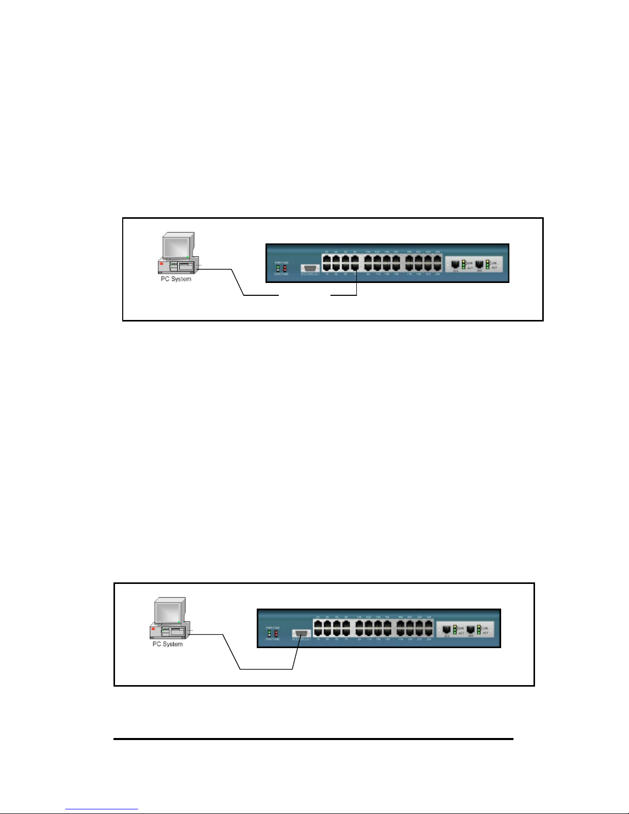
l Users can use a RS-232 non-crossover serial cable to connect the PC’S COM port to the switch
console port.
l The switch system provides the RS-232 interface with baud rate 9600-8-n-1.
l Use terminal emulation program ( e.g. Windows HyperTerminal, NetTerm) to configure the
switch system.
Notice: When using HyperTerminal with Microsoft Windows 2000, ensure that you have
Windows 2000 Service Pack 2 or later version was installed. With Windows Service Pack 2, the
arrow keys function properly in HyperTerminal’s VT100 emulation.
2.2. PC COM Port Setting
l Baud rate= 9600
l Data bits= 8
l Parity= None
l Stop bits= 1
l Flow control= None
2.3. Connecting to the Switch Web Port
l Users can use a CAT-5 cable to connect the PC ’s LAN port to one of the switch Ethernet port.
l Use web browser program (e.g. Internet Explorer, Netscape…) to configure the switch system.
Switch System
CAT-5 cable
Switch System
Page 8

24+2G Web Smart-switch User Manual
Revision 1.0- 8
2.3.1. Advantage of Web Smart Switch
l No proprietary program, no installation, no learning. It’s the most painless way for IT/MIS
person to use,
l Cross-platform support. You could configure the switch by web browser on any platform (e.g.
Windows ME, Windows XP, Windows Server 2003, UNIX, Linux, Macintosh…).
l Router awareness, real remote control. You could configure the switch from a remote PC that
across a router.
l Unicast management, no broadcast management packets. Only the switch that you want to
manage is involved in, no broadcast packets noise all over the network.
Page 9
24+2G Web Smart-switch User Manual
Revision 1.0- 9
3. Operation Notice
3.1. Console Function Keys
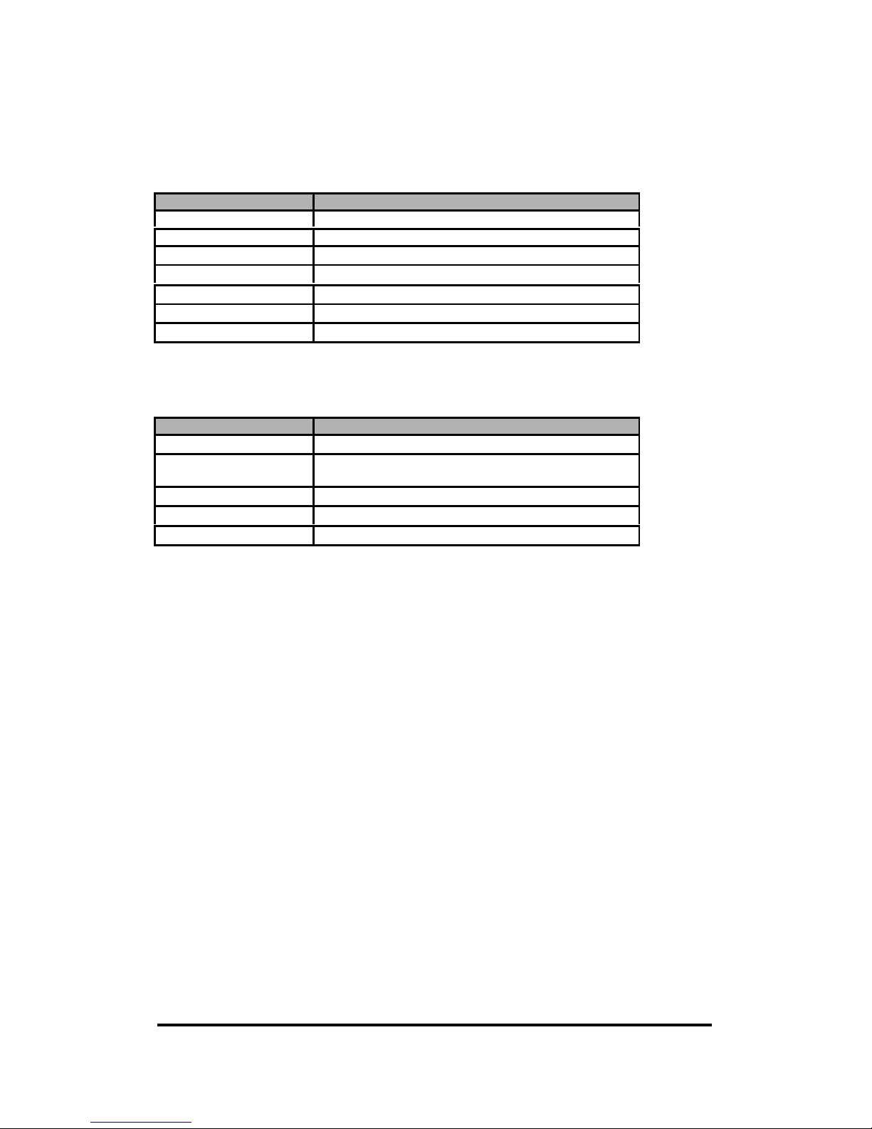
The following generic function keys provide functon in all of the menus:
Key Fuction
Tab/ Move the cursor to right item.
Backspace/ Move the cursor to left item.
↑ Move the cursor to up item.
↓ Move the cursor to down item.
Space Toggle selected item to next configuration
Enter Select action.
Esc Back to previous status.
3.2. Console Action Item
The following generic action items provide functon in all of the menus:
Key Fuction
<Quite> Exit this page and return to previous menu.
<Edit> Configure all items. Press ”Enter” key will set configure
and press “Esc” key will go back to action menu line.
<Save> Save the configuration that you had changed.
<Page Up> Back to previous page.
<Page Down> Go to next page.
Page 10
24+2G Web Smart-switch User Manual
Revision 1.0- 10
4. Login
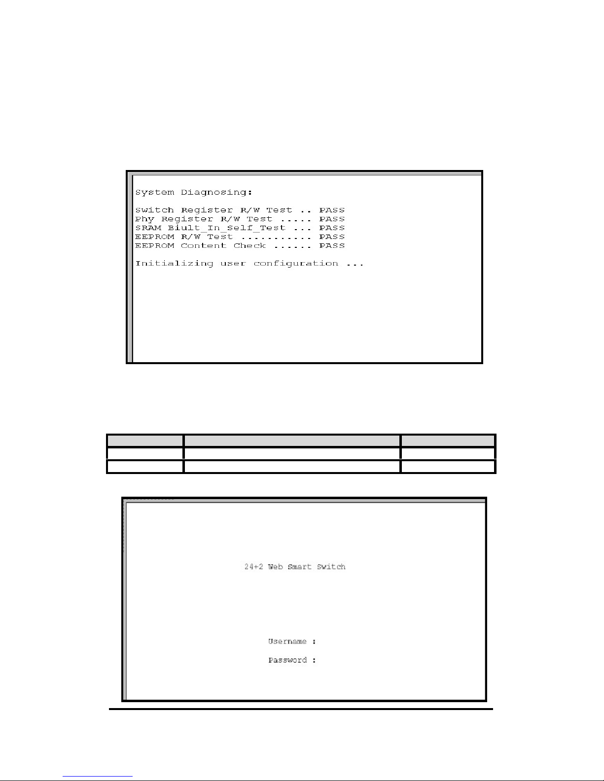
4.1. Power-On Self Testing
When the power is supplied to the switch system, power-on self testing is running. The result of
power-on self testing is output to the console port. Each diagnostic item has either “Passed” or
“Failed” result. If one of the diagnostic items failed, the whole initialization procedure will stop.
4.2. Console Login
When you connect to the switch with a terminal emulation program, a login screen is displayed. Enter
a user name and password to login to access the switch.
Item Option Default Value
Username Max:6, Min:1 characters, case sensitive web
Password Max:6, Min:1 characters, case sensitive smart
Page 11

24+2G Web Smart-switch User Manual
Revision 1.0- 11
4.3. Web Login
4.3.1. Setting IP Address by Console Port
When you are going to login to the web pages, you have to set the IP address properly first. You could
login with the default IP address: 192.168.1.1. But you have to make sure this IP could work in your
network environment. Or, you have to re-configure the IP address, subnet mask and default gateway.
First login with the console port
Second, go to the Main Menu\ Misc Operation\ “IP Configuration” screen. Then, set the IP address
properly.
Page 12
24+2G Web Smart-switch User Manual
Revision 1.0- 12
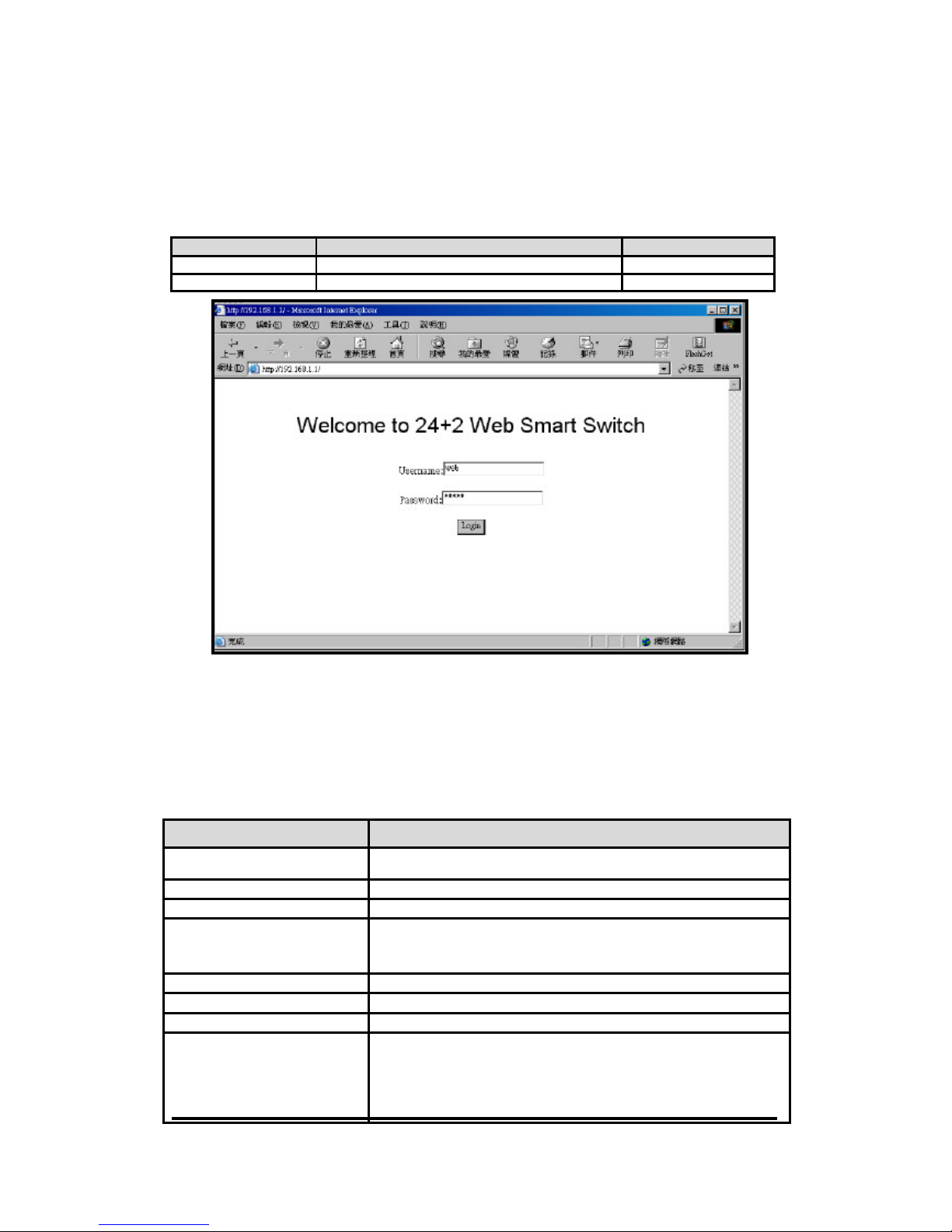
4.3.2. Login with a Web Brower
When you connect to the switch with a web browser, a login screen is displayed. Enter a user name
and password to login to access the switch.
Items Option Default Value
Username Max: 6, Min:1 characters, case sensitive web
Password Max: 6, Min:1 characters, case sensitive smart
5. Console User Interface
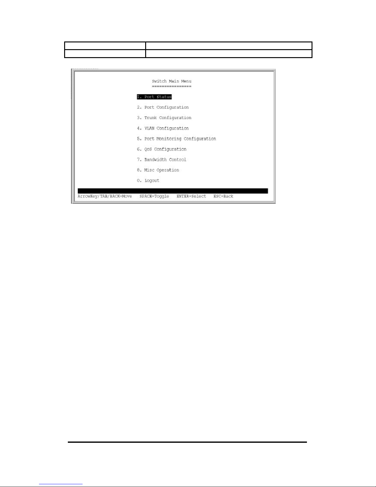
5.1. Main menu
This is the main menu of the switch console software.
Item Description
Port Status
Display current status: enabled/disabled, link up/down, speed/duplex and
flow control of each port.
Port Configuration Configure enable state, speed/duplex, and flow control for each port
Trunk Configuration Configure the trunk groups.
VLAN Configuration Configure the VLAN groups
1. VLAN Mode Configuration
2. Advanced 802.IQ VLAN Configuration
Port Monitoring Configuration Configure port monitoring.
QoS Configuration Configure QoS mode, 802.1p priority and static port priority.
Bandwidth Control Configure input rate or output rate of each port.
Misc Operation Miscellaneous Operation
1. Advanced Switch Configuration
2. Password Setting
3. Restore to Default Configuration
4. Reboot System
Page 13
24+2G Web Smart-switch User Manual
Revision 1.0- 13
5. System Information
Logout Logout and login menu.
Page 14
24+2G Web Smart-switch User Manual
Revision 1.0- 14
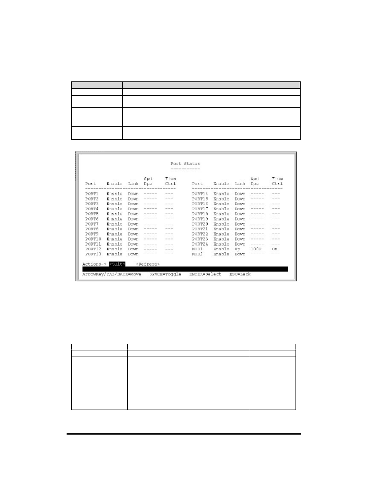
5.2. Port Status
Display current status: enabled/disabled, link up/down, speed/duplex and flow control of each port.
Item Description
Enable Enable / Disable
Link Status Up/Down.
If the port was disabled, the item is displayed as “---“ .
Spd / Dpx 100F/ 100H/ 10F/ 10H.
F: Full duplex, H: Half duplex.
If the port was disabled or link sown, the item is displayed as “---“ .
Flow Control On / Off
If was port disabled or link sown, the item is displayed as “---“ .
Special item in the Action Menu:
<Refresh>: Re-read the status from each port and refresh the whole screen.
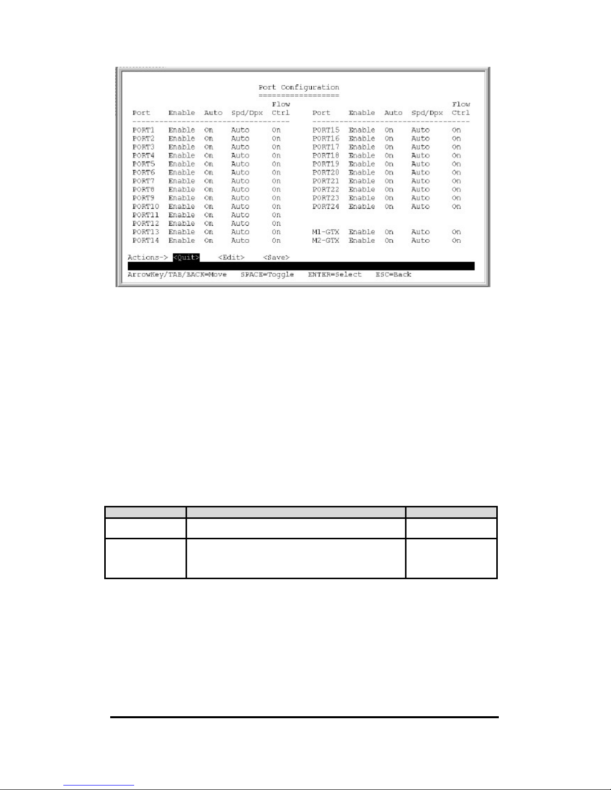
5.3. Port Configuration
Configure enable state, auto-negotiation, speed/duplex, and flow control for each port.
Item Option Default value
Enable Enable / Disabled Enable
Auto On /Off.
If the port was disabled, the item is displayed as “---“ .
If this set to Off, then Spd / Dpx should not be set to
Auto
On
Spd / Dpx Auto/ 100F/ 100H /10F /10H.
F: Full duplex, H: Half duplex.
If the port was disabled, the item is displayed as “---“ .
Auto
Flow Control On / Off
If port disabled, the item is displayed as “---“ .
On
Page 15
24+2G Web Smart-switch User Manual
Revision 1.0- 15
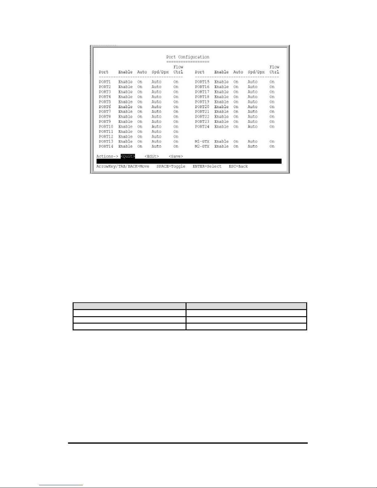
Notice: In this example, when Port 3 and Port 4 are configured to be trunk group 1, thus Port3/Port4
will be disappeared from the list and replaced by Trunk 1 indication.
5.4. Trunk Configuration
Configure the trunk groups. There are max. 7 trunk groups can be configured. User can arbitrarily
select up to four ports from port1~port24 or port25~port26 to make a trunk group.
Notice:
1: The 10/100Mbps port cannot be trunked with gigabit port.
2: All ports in the same trunk group will be treated as a single port. If VLAN group exist, all the
members in a trunk group must be in the same VLAN group.
Items Option Default value
Each trunk group Enable/Disable, which means if current trunk group is
enabled or disabled.
Disabled
Each port A “v” mark can be selected for T1~T7, which means to
which trunk group current port is belonging.
This option is exclusive, that is to say, each port could only
be one of the trunk groups.
Not a trunk member
Page 16
24+2G Web Smart-switch User Manual
Revision 1.0- 16
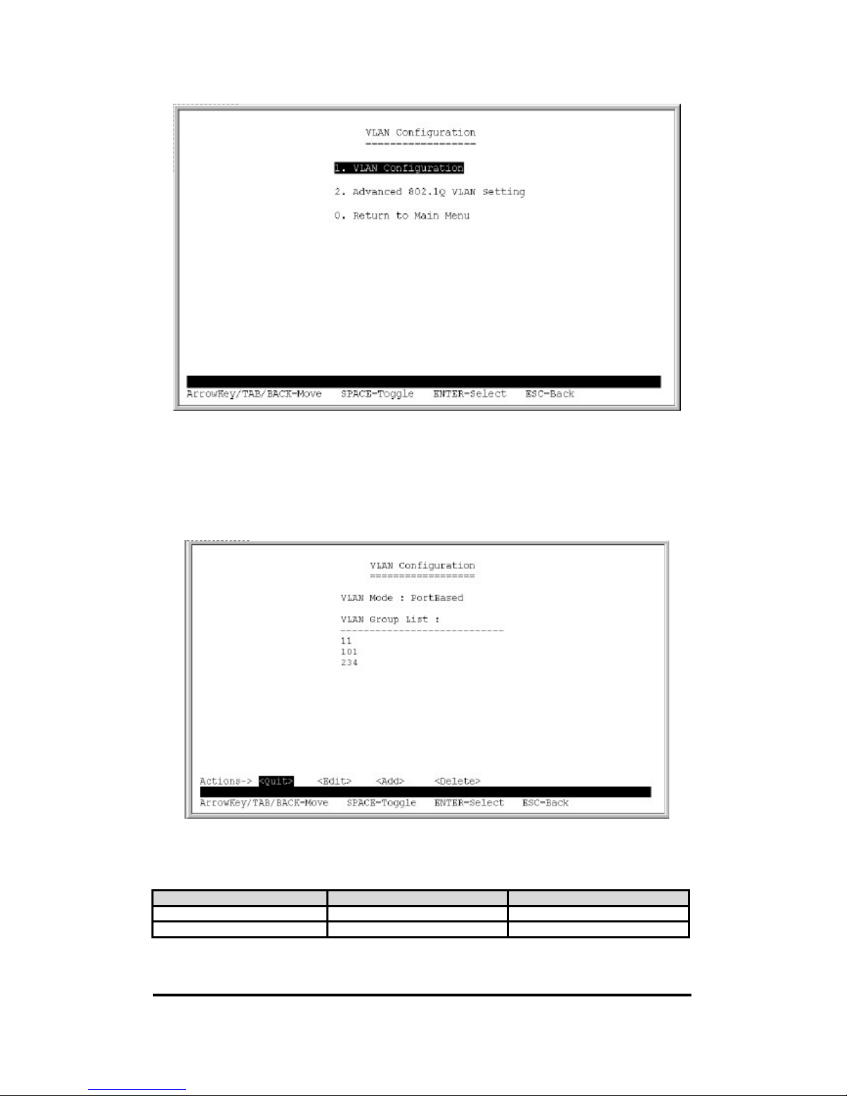
5.5. VLAN Configuration
A Virtual LAN (VLAN) is a logical network group that limits the broadcast domain. It allows you to
isolate network traffic so only member of the VLAN receive traffic from the same VLAN members.
Basically, creating a VLAN within a switch is logically equivalent of reconnecting a group physically.
The XP-3241 supports port-based and tag-based (802.1Q) VLAN mode. In the default configuration,
VLAN is disabled. If enabled the 802.1Q VLAN, initially, all ports on the switch belong to default
VLAN, VID is 1.
Notice: You cannot delete the default VLAN group in 802.1Q VLAN mode.
Item Description
VLAN Configuration Add / Delete VLAN groups.
Advanced 802.1Q VLAN Setting Ingress filters configuration.
Return to Main Menu Back to main menu.
Page 17
24+2G Web Smart-switch User Manual
Revision 1.0- 17
5.5.1. VLAN Mode: Port-based VLAN
Packets can be forwarded only to members of the same VLAN group.
Special items in the Action Menu:
<Add>: Add a new group and enter the editing page.
<Delete>: Delete an existing group.
Item Option Default value
Group ID 1~255.(max. 24 VLAN group) 0
Each port --- / Member ---
Page 18
24+2G Web Smart-switch User Manual
Revision 1.0- 18
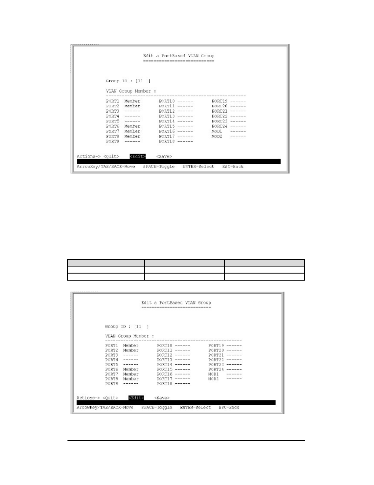
5.5.2. Port-based VLAN Group <Add>/<Edit>Menu
Packets are delivered to only members of the same VLAN group. Note all unselected ports are treated
as belonging to another single VLAN. If the port-based VLAN enabled, the VLAN-tagging is
ignored.
Item Option Default value
Group ID 1~255.(max. 24 VLAN group) 0
Each port --- / Member ---
Page 19
24+2G Web Smart-switch User Manual
Revision 1.0- 19
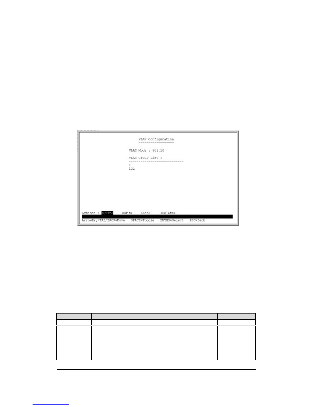
5.5.3. VLAN Mode: 802.IQ VLAN
Packets are delivered to the members of the same VLAN group, which is recognized by 802.IQ tag.
PVID(Port VID): Set the port VLAN ID that will be assigned to untagged traffic on a given port.
This feature is useful for accommodating devices that you want to participate in the VLAN but don ’t
support tagging.
Each port of XP-3241 allows user to assign one PVID, range from 1~255, default PVID is 1. The
PVID must be as same as the VLAN ID that the port belongs to which VLAN group, or the untagged
traffic will be dropped.
Special items in the Action Menu:
<Add>: Add a new group and enter the editing page.
<Delete>: Delete an existing group.
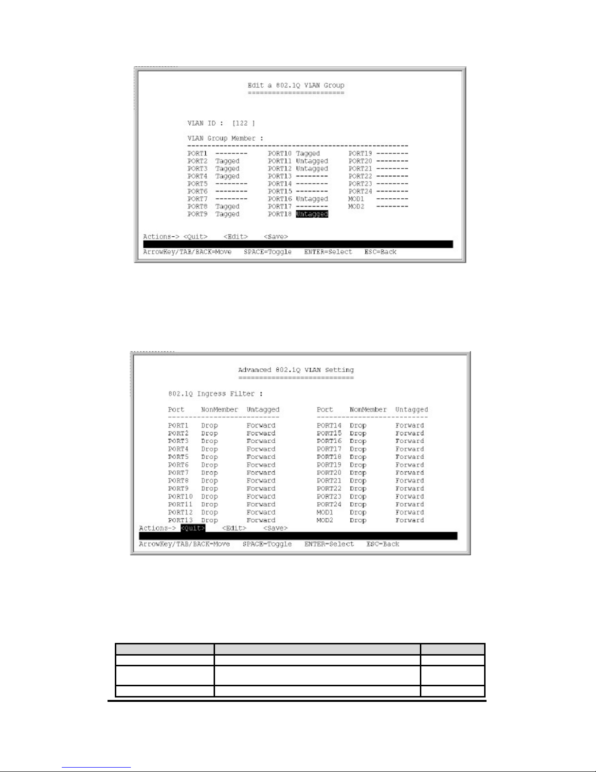
5.5.4. 802.IQ VLAN Group <Add>/ <Edit> Menu
If the trunk groups exists, you can see it (e.g. TRUNK1, TRUNK2 …) after port24. And, you can
configure it to be a member of the VLAN group.
Notice: The limitation of VLAN ID (range from 1~255, not from 1~4094) is chip's limitation.
Items Option Default value
VLAN ID 1~255 (max. 24 VLAN group) 0
Each port ---/Tagged/Untagged.
a. ---: This port is NOT a member of this VLAN group.
b. Tagged: this port is the member of this VLAN group
and outgoing frames are VLAN-tagged frame.
c. Untagged: this port is the member of this VLAN group
and outgoing framed are NOT VLAN-tagged frames.
---
Page 20
24+2G Web Smart-switch User Manual
Revision 1.0- 20
5.5.5. Advanced 802.1Q VLAN Configuration
Ingress filters configuration.
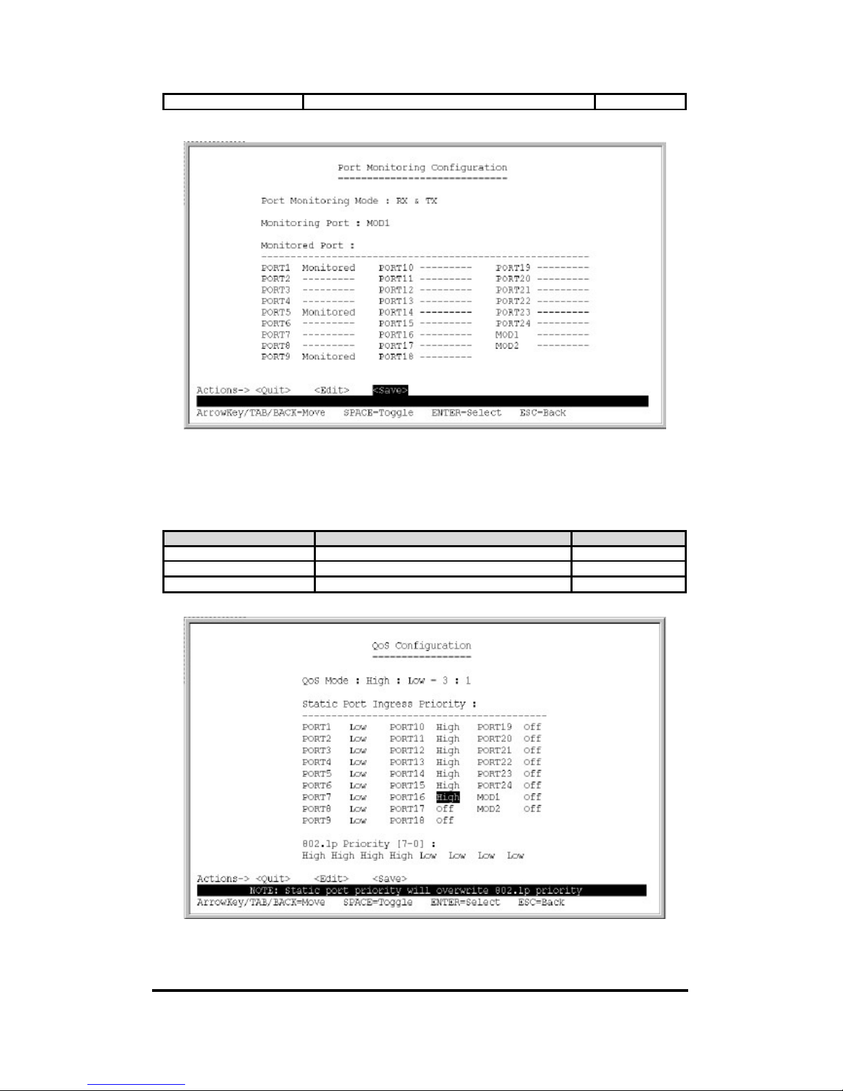
5.6. Port Monitoring Configuration
Port monitoring is forwarding specified direction of packets from several monitored ports to a
specified monitoring port.
Items Option Default value
Port Monitoring Mode Disable / RX / TX / RX & TX Disable
Port Monitoring Port PORT1~PORT24, PORT25~26.
Any single port but is not a trunk group
PORT 1
Monitoring Port --- / Monitored. ---
Page 21
24+2G Web Smart-switch User Manual
Revision 1.0- 21
Each single port and trunk group could be a member.
5.7. QoS Configuration
Configure QoS mode, 802.1p priority and static port priority.
Items Option Default value
Qos Mode Disable / all high before low / weight 3:1 /5:1 / 7 :1 Weight3:1
Each port Off / Low / High Off
802.1p Priority Low / High L L L L H H H H
5.8. Bandwidth Control
Page 22
24+2G Web Smart-switch User Manual
Revision 1.0- 22
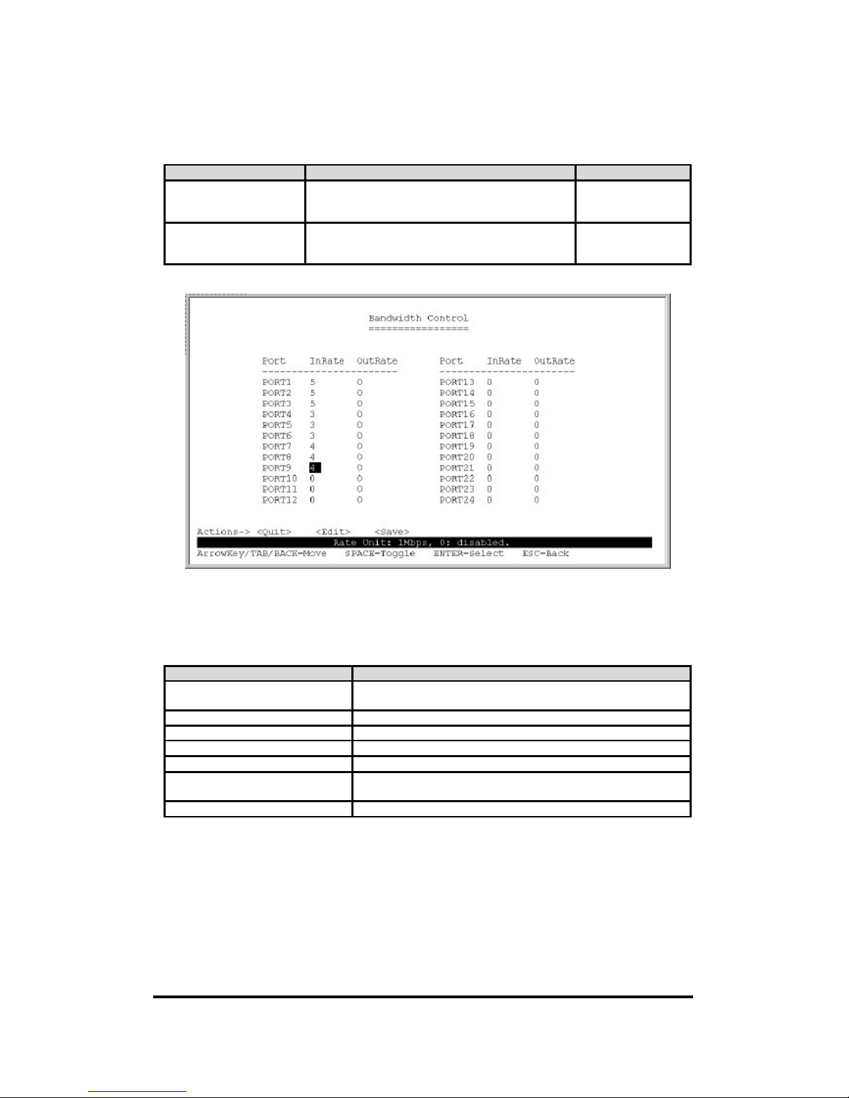
Configure input rate or output rate of each port. For example: assume port 1 is 10Mbps, users can set
it's effective Output Rate to 1Mbps, Input Rate to 500Kbps. XP-3241 will perform flow control or
backpressure to confine the to ingress rate to meet the specified rate.
Items Option Default value
InRate 0~99.
0: means disable rate control.
1~99: means the rate will be 1%~99%.
0
OutRate 0~99.
0: means disable rate control.
1~99: means the rate will be 1%~99%.
0
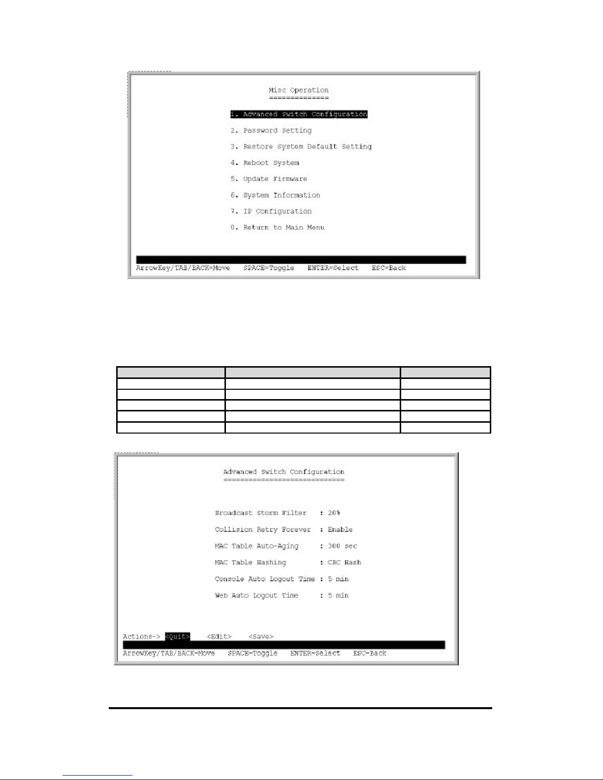
5.9. Misc Operation
Miscellaneous operation of the switch.
Item Description
Advanced Switch Configuration Configure advanced switch function: BSF, Collision retry, age-out
time …
Password Setting Change user name and password.
Restore System Default Setting Restore to manufacture default.
Reboot System Reboot switch.
System Information Firmware version, chip revision.
IP Configuration Configure IP address, subnet mask and default gateway of the
switch.
Return to Main Menu Back to main menu.
Page 23
24+2G Web Smart-switch User Manual
Revision 1.0- 23
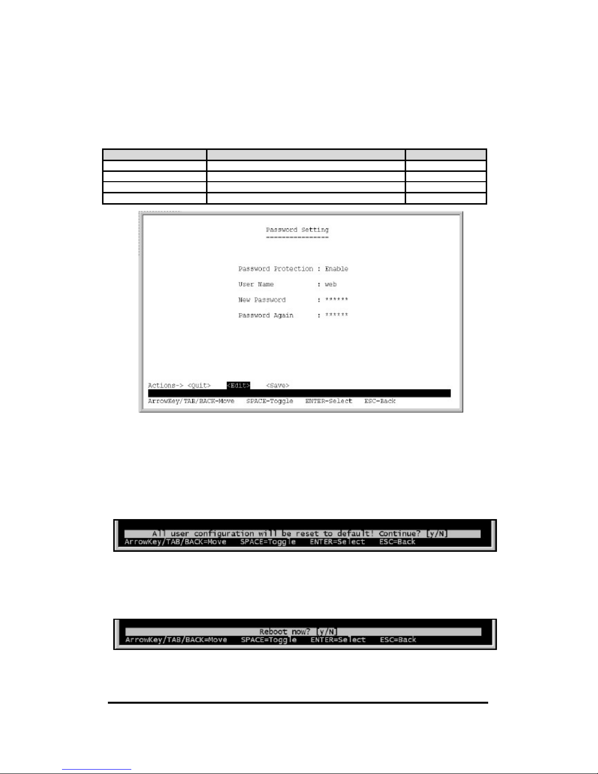
5.9.1. Advanced Switch Configuration
Configure advanced switch functions: BSF, Collision retry, age-out time...
Items Option Default value
Broadcast Storm Filter Off / 5% / 10% /20% Off
Collision Retry Forever Disable / Enable Disable
MAC Table Auto-Aging Disable /150 / 300/ 600 seconds 300 seconds
MAC Hash CRC Hash / Direct Map CRC Hash
Auto Logout Time Never /5 /10 /20 minutes 5 minutes
Page 24
24+2G Web Smart-switch User Manual
Revision 1.0- 24
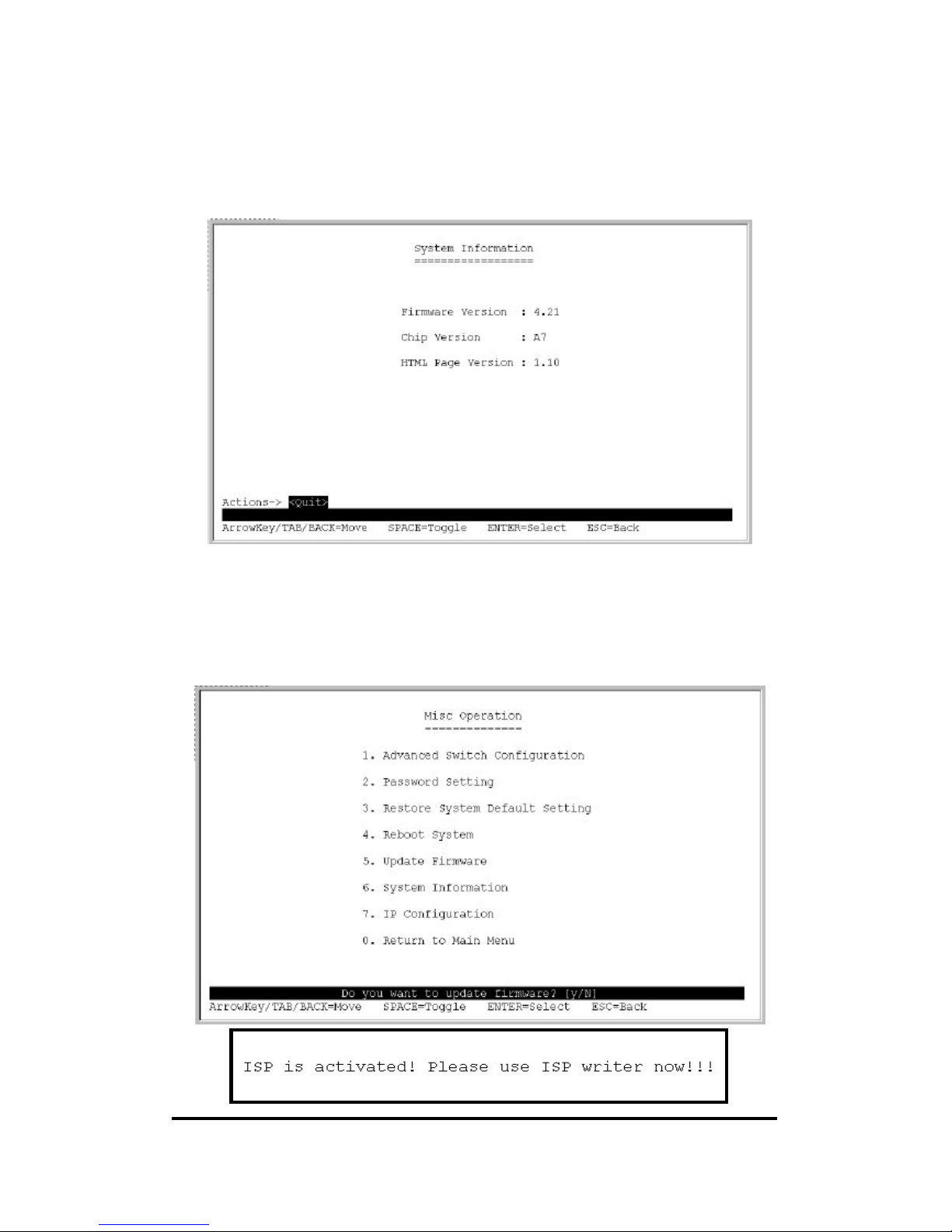
5.9.2. Password Setting
You should change the default password to be sure that your system is secured.
Items Option Default value
Password Protection Enable / Disable Enable
User name Max: 6, Min: 1 characters, case sensitive web
New Password Max: 6, Min 1 characters, case sensitive
Re-enter Password Max: 6, Min: 1 characters, case sensitive
5.9.3. Restore System Default Setting
Restore to default manufacture setting.
5.9.4. Reboot System
Reboot the switch system.
Page 25
24+2G Web Smart-switch User Manual
Revision 1.0- 25
5.9.5. System Information
This page displays the firmware version and chip version.
5.9.6. Update Firmware
Please reference Appendix A that detail upgrade method.
Page 26
24+2G Web Smart-switch User Manual
Revision 1.0- 26
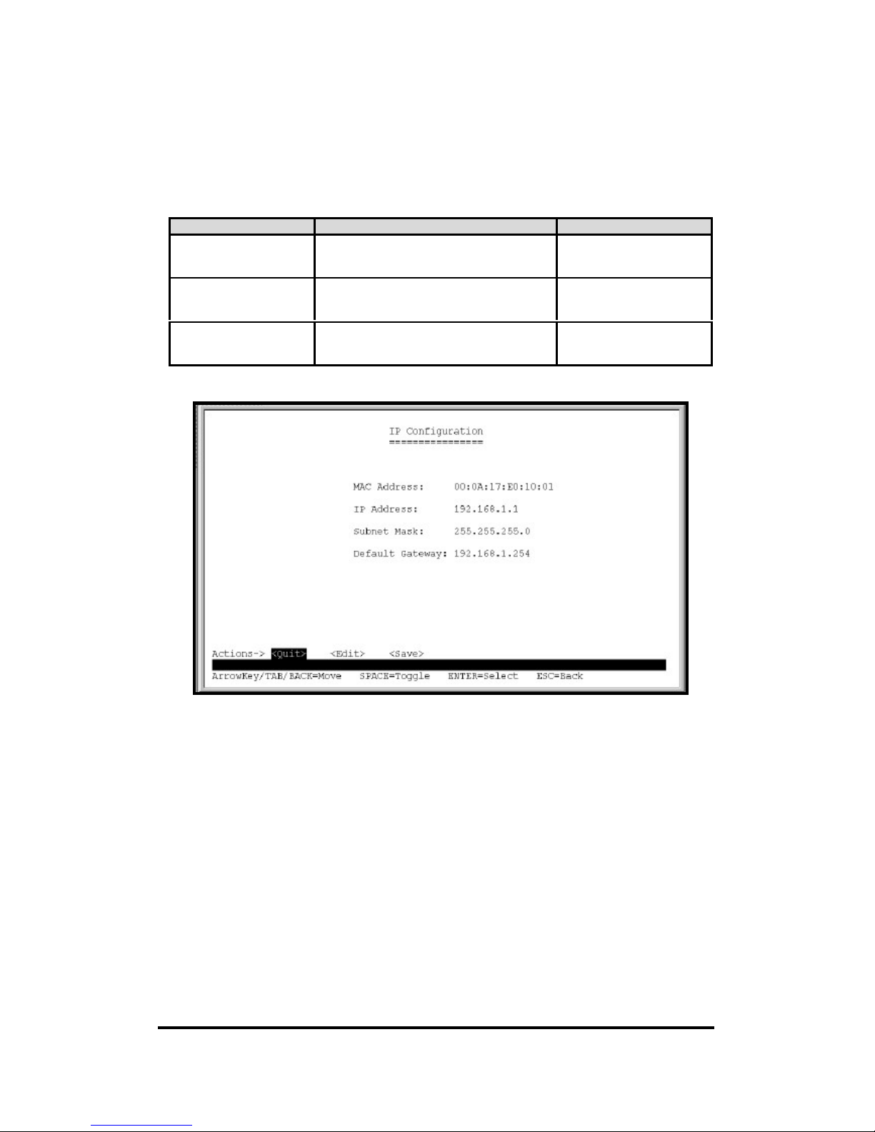
5.9.7. IP Configuration
Configure IP address, subnet mask and default gateway of the switch.
Items Option Default Value
IP Address ***.***.***.***
*is represent a digit from 0~9,***is range
from 0 to 255.
192.168.1.1
Subnet Mask ***.***.***.***
*is represent a digit from 0~9,***is range
from 0 to 255.
255.255.255.0
Default Gateway ***.***.***.***
*is represent a digit from 0~9,***is range
from 0 to 255.
192.168.1.254
Page 27
24+2G Web Smart-switch User Manual
Revision 1.0- 27
6. Web User Interface
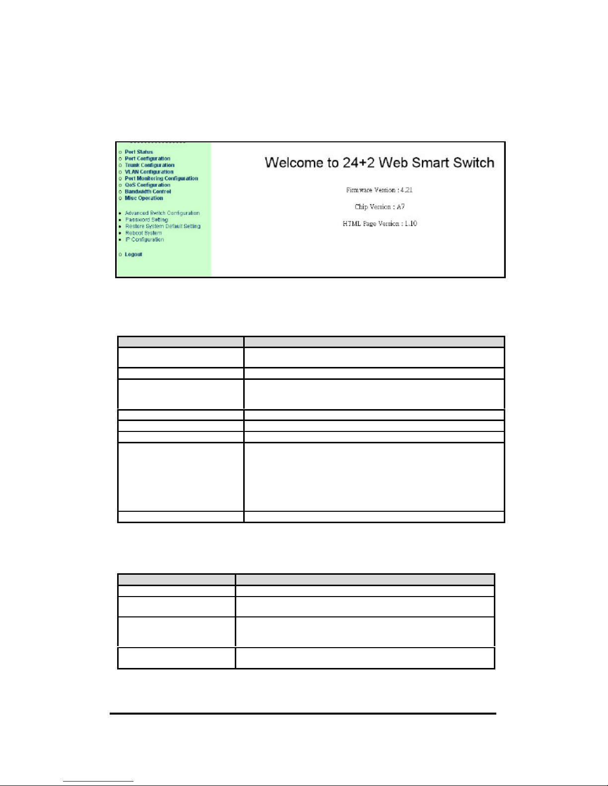
6.1. Welcome page
This is page will show switch information includes the firmware and software massage.
6.2. Main Menu
This is the main menu of the switch web software.
Item Description
Port Status Display current status: enabled/disabled, link up/down, speed/duplex
and flow control of each port.
Port Configuration Configure enable state, speed/duplex, and flow control for each port
VLAN Configuration Configure the VLAN groups
1. VLAN Mode Configuration.
2. Advanced 802.1Q VLAN Configuration
Port Monitoring Configuration Configure port monitoring.
QoS Configuration Configuration QoS mode, 802.1p priority and static port priority,
Bandwidth Control Configuration input rate or output rate of each port.
Misc Operation Miscellaneous Operation
1. Advanced Switch Configuration
2. Password Setting
3. Restore to Default Configuration
4. Reboot System
5. System Information
6. IP Configuration
Logout Logout and login menu.
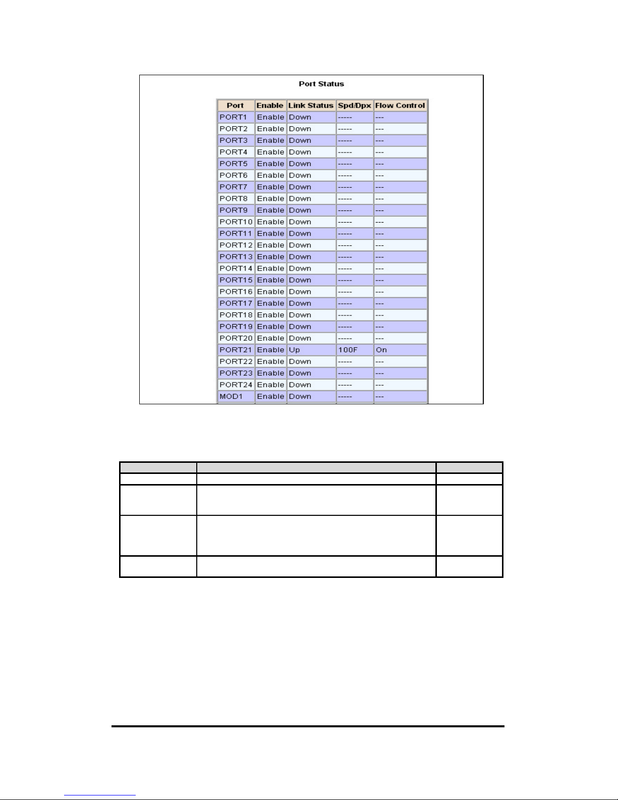
6.3. Port Status
Display current status: enabled/disabled, link up/down, speed/duplex and flow control of each port.
Items Description
Enable Enable / Disable
Link Status Up / Down.
If the port was disabled, the item is displayed as “---“ .
Spd / Dpx 100F/100H/10F/10H.
F: Full duplex, H: Half duplex.
If the port was disabled or link down, the item is displayed as “---“ .
Flow Control On /Off
If the port was disabled or link down, the item is displayed as “---“ .
Page 28
24+2G Web Smart-switch User Manual
Revision 1.0- 28
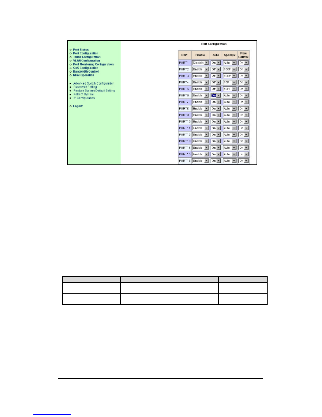
6.4. Port Configuration
Configure enable state, auto-negotiation, speed/duplex, and flow control for each port.
Items Option Default value
Enable Enable / Disable Enable
Auto On /Off.
If the port was disabled, the item is displayed as “---“ .
If this set to Off, then Spd/Dpx should not be set to Auto.
On
Spd / Dpx Auto/100F/100H/10F/10H.
F: Full duplex, H: Half duplex.
If the port was disabled or link down, the item is displayed as “--
-“ .
Auto
Flow Control On /Off.
If port disabled, the item is displayed as “---“ .
On
Page 29
24+2G Web Smart-switch User Manual
Revision 1.0- 29
Notice:
In this example, Port 3 and Port 4 are belonging to trunk group 1, thus Port3/Port4 are disappeared
and replaced by Trunk 1.
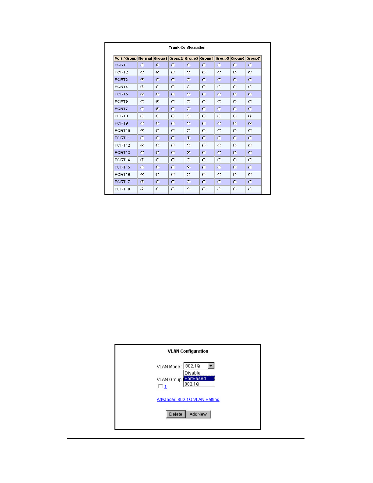
6.5. Trunk Configuration
Configure the trunk groups. There are max. seven trunk groups can be configured. User can
arbitrarily select up to four ports from port 1~port 24 or port 25~port 26 to make a trunk group.
Notice:
1: The 10/100Mbps port can not be trunked with gigabit port.
2: All ports in the same trunk group will be treated as a single port. If VLAN group exist, all of the
members in a trunk group must be in the same VLAN group.
Items Option Default value
Each trunk group Enable / Duplex, which mean if current trunk
group is enabled or disabled.
Disabled
Each port This option is exclusive, that is to say, each port
could only be one of the trunk groups.
Not a trunk member
Page 30
24+2G Web Smart-switch User Manual
Revision 1.0- 30
6.6. VLAN Configuration
A Virtual LAN (VLAN) is a logical network group that limits the broadcast domain. It allows you to
isolate network traffic so only members of the VLAN receive traffic from the same VLAN members.
Basically, creating a VLAN within a switch is logically equivalent of reconnecting a group of network
devices to another Layer 2 switch. However, all the network devices are still plug into the same
switch physically.
The XP-3241 supports port-based and tag-based ( 802.1Q ) VLAN mode. In the default configuration,
VLAN is disabled. If enable the 802.1Q VLAN, initially, all ports on the switch belong to default
VLAN, VID is 1.
Notice: You cannot delete the default VLAN group in 802.1Q VLAN mode.
Page 31
24+2G Web Smart-switch User Manual
Revision 1.0- 31
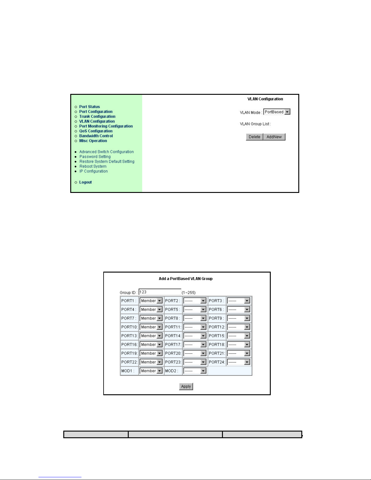
6.6.1. VLAN Mode: Port-based VLAN
Packets are delivered to only the members of the same VLAN group.
Special buttons :
<Add New>: Add a new group and enter the editing page.
<Delete>: Delete an existing group.
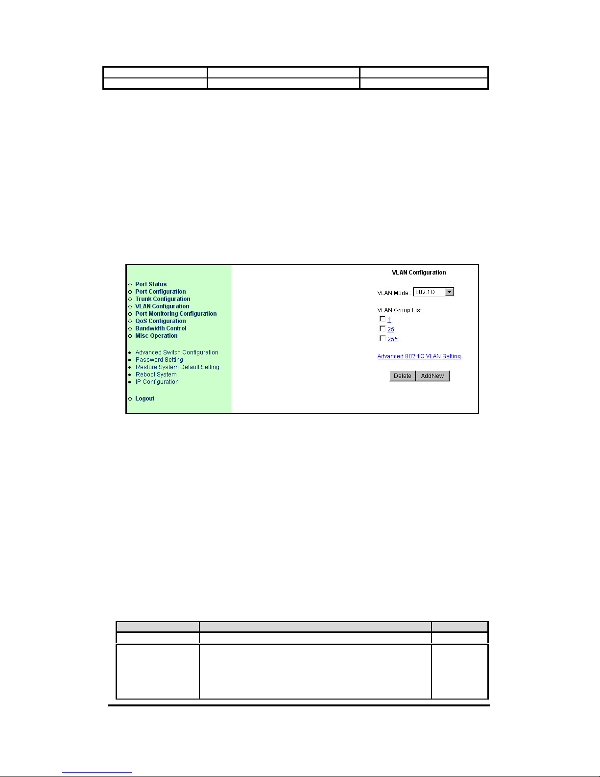
6.6.2. Port-based VLAN Group <Add> / <Edit> Menu
Packets are delivered to only the members of the same VLAN group. Note all unselected ports are
treated as belonging to another single VLAN. If the port-based VLAN enabled , the VLAN-tagging is
ignored.
Items Option Default value
Page 32
24+2G Web Smart-switch User Manual
Revision 1.0- 32
Group ID 1~255 (max. 24 VLAN group) 0
Each port --- / Member ---
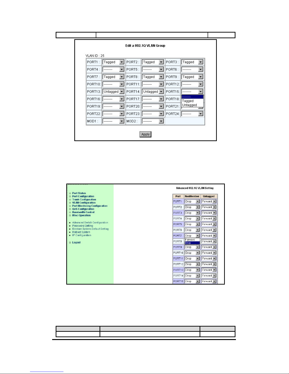
6.6.3. VLAN Mode: 802.1Q VLAN
Packets are delivered to the members of the same VLAN group, which is recognized by 802.1Q tag.
PVID (Port VID): Set the port VLAN ID that will be assigned to untagged traffic on a given port.
This feature is useful for accommodating devices that you want to participate in t he VLAN but that
don't support tagging. Each port of XP-3241 allows user to assign one PVID, range from 1~255,
default PVID is 1. The PVID must be as same as the VLAN ID that the port belongs to which VLAN
group, or the untagged traffic will be dropped.
Special buttons :
<Add New>: Add a new group and enter t he editing page.
<Delete >: Delete an e xisting group.
6.6.4. 802.1Q VLAN Group <Add> / <Edit> Menu
If the trunk groups exist, you can see it (e.g. TRUNK1, TRUNK2...) after port24. And, you can
configure it to be a member of the VLAN group.
Notice: The limitation of VLAN ID (range fro m 1~255, not from 1~4094) is chip's limitation.
Items Option Default value
VLAN ID
1~255 (max. 24 VLAN group)
0
Each port
---/Tagged/Untagged.
1.---: This port is NOT a member of this VLAN group
2. Tagged: this port is the member of this VLAN group
and outgoing frames are VLAN-tagged frames.
3. Untagged: this port is the member if this VLAN group
---
Page 33
24+2G Web Smart-switch User Manual
Revision 1.0- 33
and outgoing frames are NOT VLAN-tagged frames.
6.6.5. Advanced 802.1Q VLAN Configuration
Ingress filters configuration.
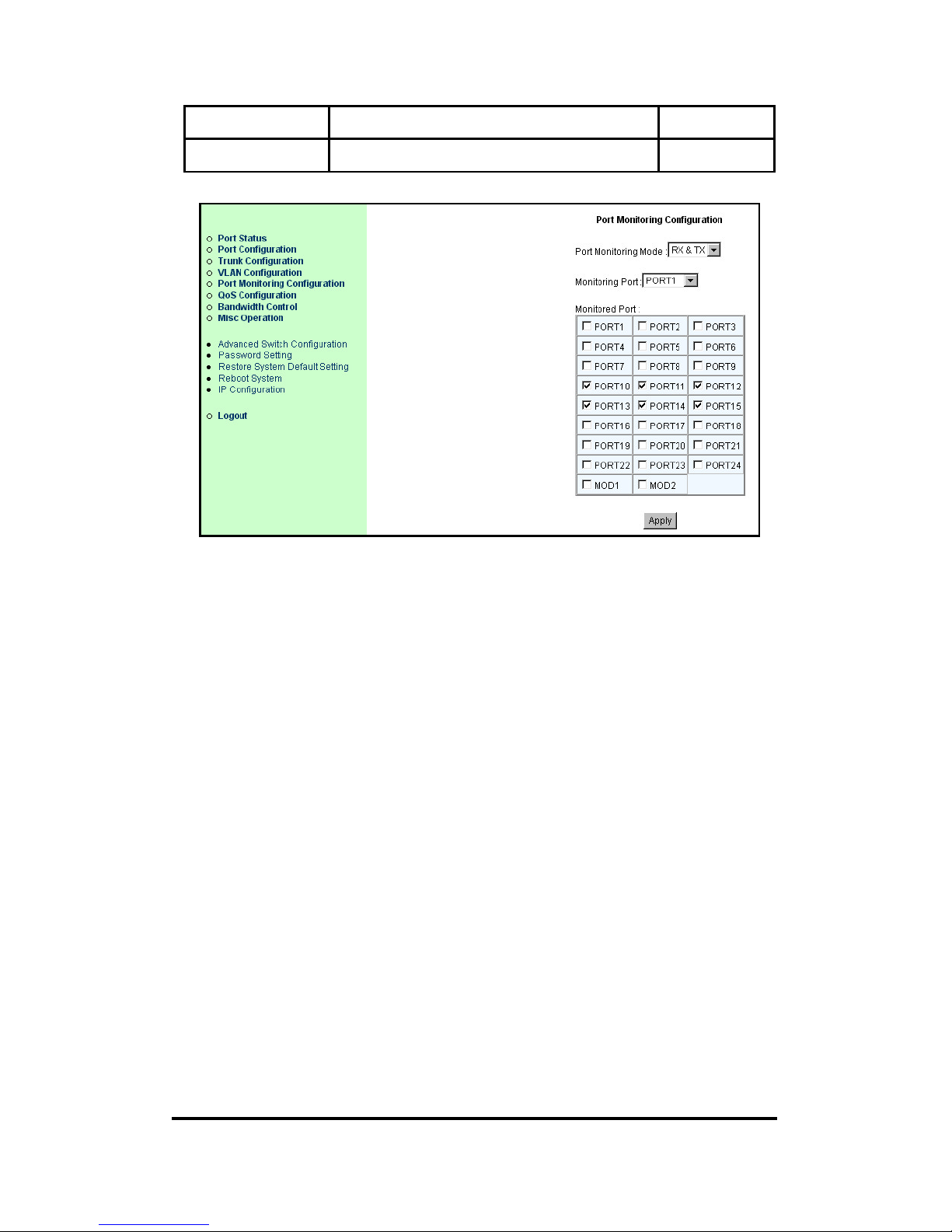
6.7. Port Monitoring Configuration
Port monitoring is forwarding specified direction of packets from several monitored ports to a
specified monitoring port.
Items Option Default value
Port Monitoring Mode Disable / RX /TX / RX & TX Disable
Page 34
24+2G Web Smart-switch User Manual
Revision 1.0- 34
Monitoring Port PORT1~PORT24, PORT25~26.
Any single port and trunk group
PORT 1
Monitored Port --- / Monitored.
Each single port and trunk group could be a member
---
Page 35
24+2G Web Smart-switch User Manual
Revision 1.0- 35
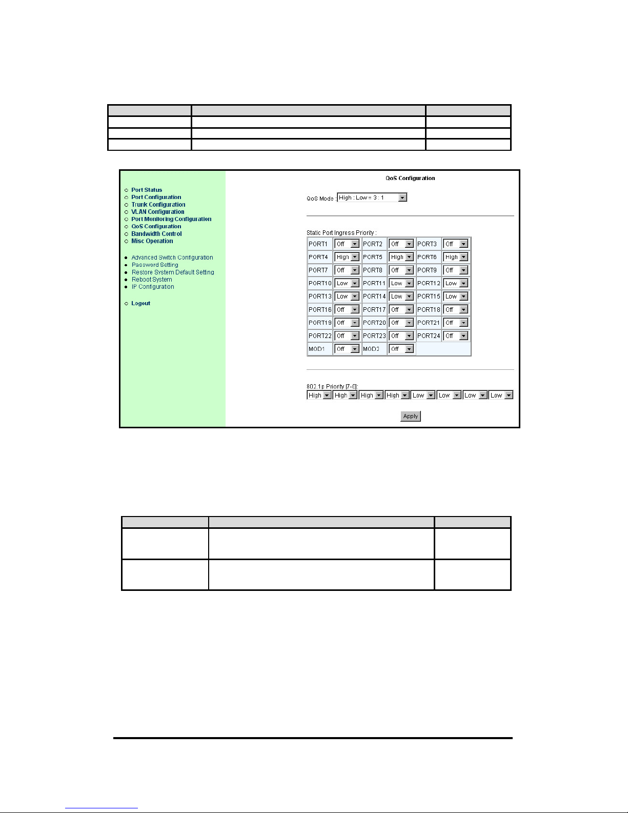
6.8. QoS Configuration
Configure QoS mode, 802.1p priority and static port priority.
Items Option Default value
Qos Mode Disable / all high before low / weight 3:1 / 5:1 / 7:1 Weight 3:1
Each port Off / Low / High Off
802.1p Priority Low / High H H H H L L L L
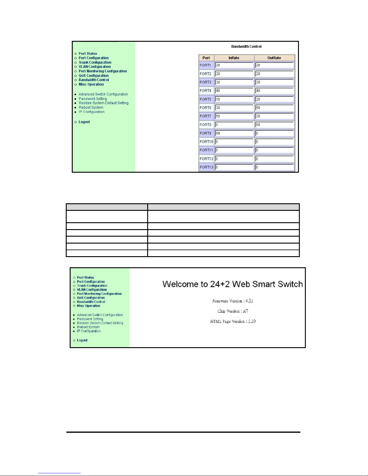
6.9. Bandwidth Control
Configure input rate or output rate of each port. For example: assume port 1 is 10Mbps, users can set
it's effective Output Rate to 1Mbps, Input Rate to 500Kbps. XP-3241 will perform flow control or
backpressure to confine the to ingress rate to meet the specified rate.
Items Option Default value
InRate 0~99.
0: means disable rate control.
1~99: means the rate will be 1%~99%.
0
OutRate 0~99.
0: means disable rate control.
1~99: means the rate will be 1%~99%.
0
Page 36
24+2G Web Smart-switch User Manual
Revision 1.0- 36
6.10. Misc Operation
Miscellaneous operation of the switch.
Item Description
Advanced Switch Configuration Configure advanced switch functions: BSF, Collision retry, age-out
time …
Password Setting Change user name and password
Restore S ystem Default Setting Restore to manufacture default.
Reboot System Reboot switch.
System Information Firmware version, chip revision,…
IP Configuration Configure IP address, subnet mask and default gateway of switch.
Page 37
24+2G Web Smart-switch User Manual
Revision 1.0- 37
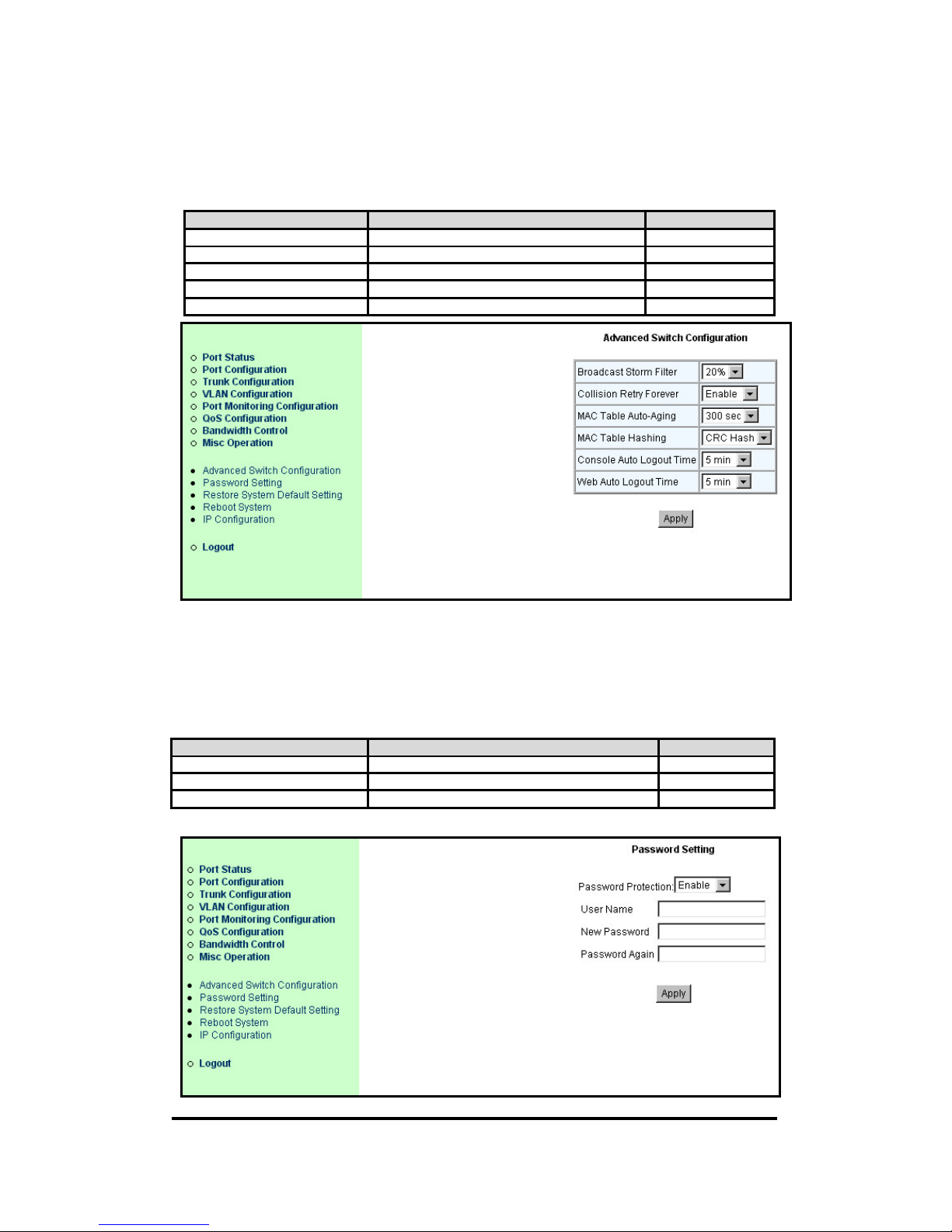
6.10.1. Advanced Switch Configuration
Configure advanced switch functions: BSF, Collision retry, age-out time...
Items Option Default value
Broadcast Strom Filter Off / 5% /10% / 20% Off
Collision Retry Forever Disable / Enable Disable
MAC Table Auto-Aging Disable / 150 / 300 / 600 seconds 300 seconds
MAC Hash CRC Hash / Direct Map CRC Hash
Auto Logout Time Never / 5 /10 / 20 minutes 5 minutes
6.10.2. Password Setting
You should change the default password ensure that your system is secured.
Items Option Default value
User name Max: 6, Mon: 1 characters, case sensitive admin
New Password Max: 6, Mon: 1 characters, case sensitive
Re-enter Password Max: 6, Mon: 1 characters, case sensitive
Page 38
24+2G Web Smart-switch User Manual
Revision 1.0- 38
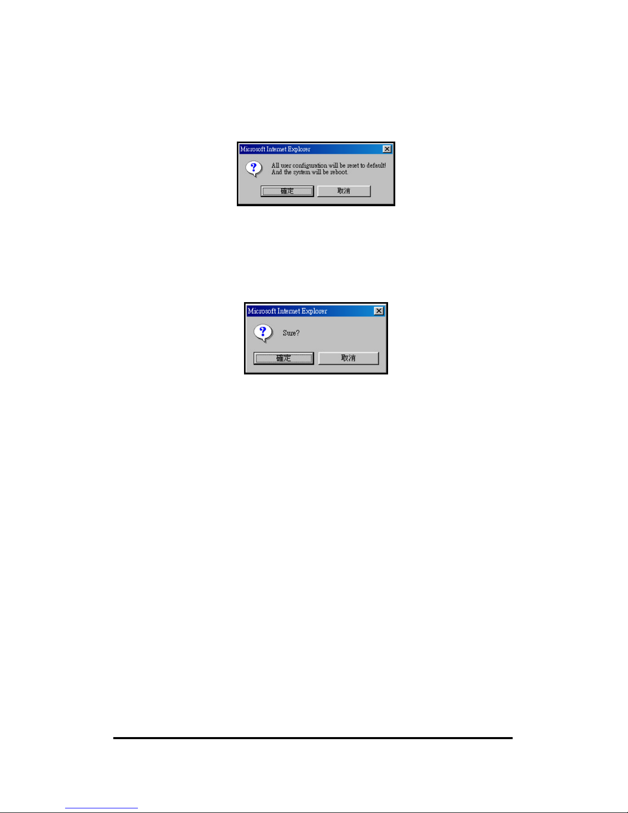
6.10.3. Restore System Default Setting
Restore to default manufacture setting.
6.10.4. Reboot System
Reboot the switch system.
Page 39
24+2G Web Smart-switch User Manual
Revision 1.0- 39
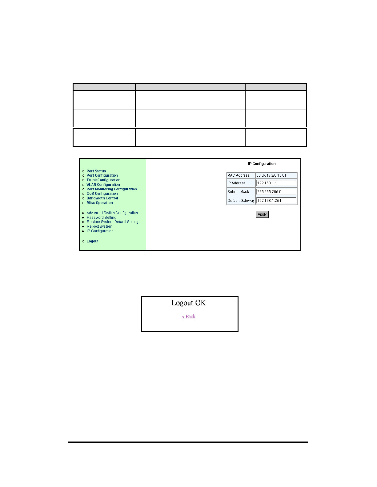
6.10.5. IP Configuration
Configure IP address, subnet mask and default gate way of the switch.
Items Option Default value
IP Address ***.***.***.***
*is represent a digit from 0~9,***is range from
0 to 255.
192.168.1.1
Subnet Mask ***.***.***.***
*is represent a digit from 0~9,***is range from
0 to 255.
255.255.255.0
Default Gateway ***.***.***.***
*is represent a digit from 0~9,***is range from
0 to 255.
192.168.1.254
6.11. Logout
Logout and back to login menu.
Page 40
24+2G Web Smart-switch User Manual
Revision 1.0- 40
Appendix A
Firmware upgrade instruction manual
Introduction:
1. Firmware version no of 4.21 is an initial release version, all further upgrade
version will base on version no. 4.21. There is a firmware upgrade utility of
8055ISP writer will also be required prior to process upgrade processes.
2. For more details about firmware upgrade, please refer to below of step by step
guidance.
3. Firmware upgraded process can be identified by console mode of product model
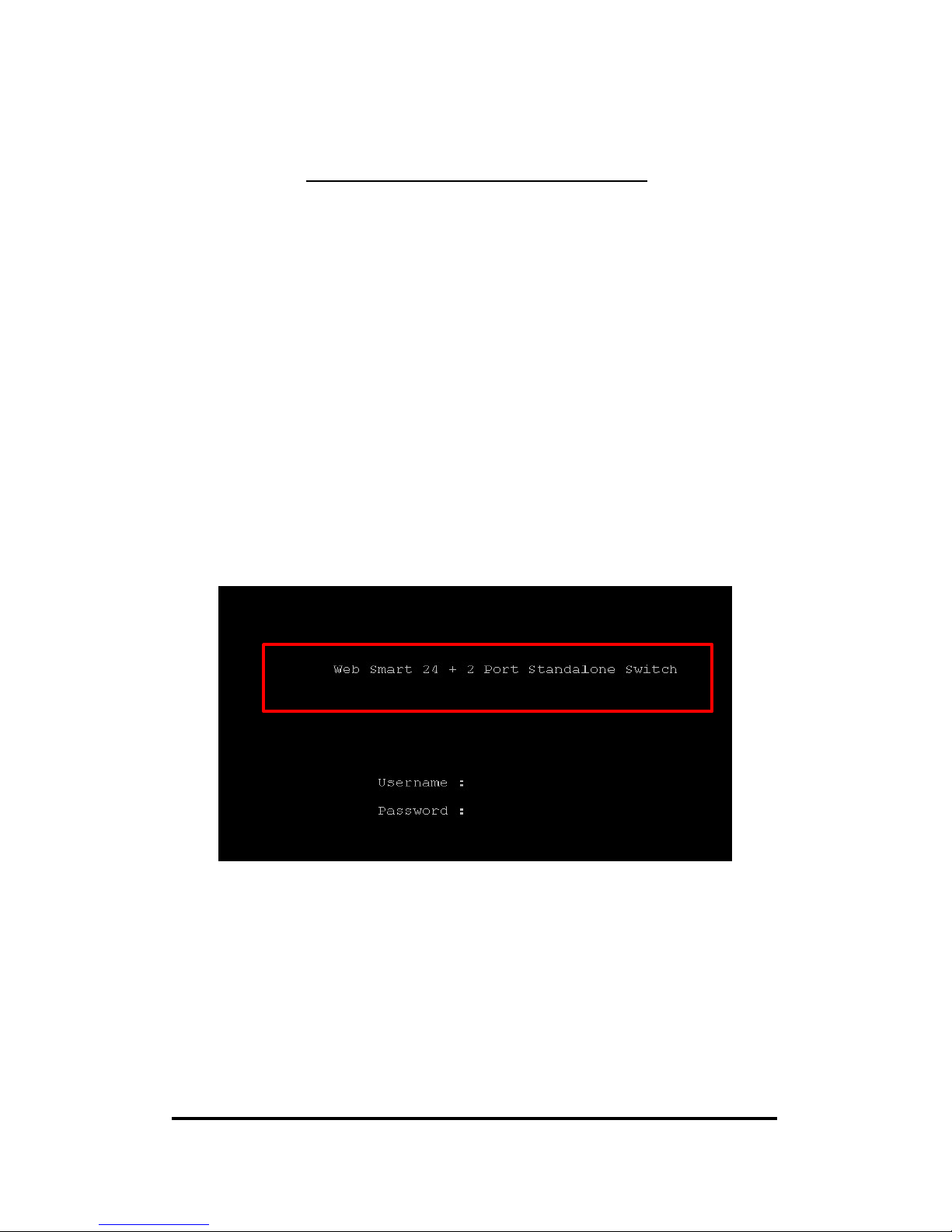
descriptions. For example, old title would be shown as Web Smart 24+2 Port
Standalone, and as it was upgraded that product model would be shown as like as
24+2 Web Smart Switch.
Below figure is shown about the page before to be upgraded.
Firmware updage guidance:
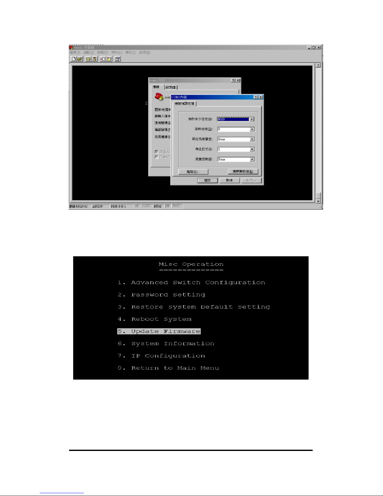
1. Click on terminal icon and entering terminal mode, please configure console port
parameters as below shown figure of 9600, 8, None, 1, None.
Page 41
24+2G Web Smart-switch User Manual
Revision 1.0- 41
2. Before you are login that you would be required to input the user name and
password. Please use web as an user name and smart as a password, and go to
the Misc operation page, select item # 5 of update firmware so that enable to
process into firmware upgrade.
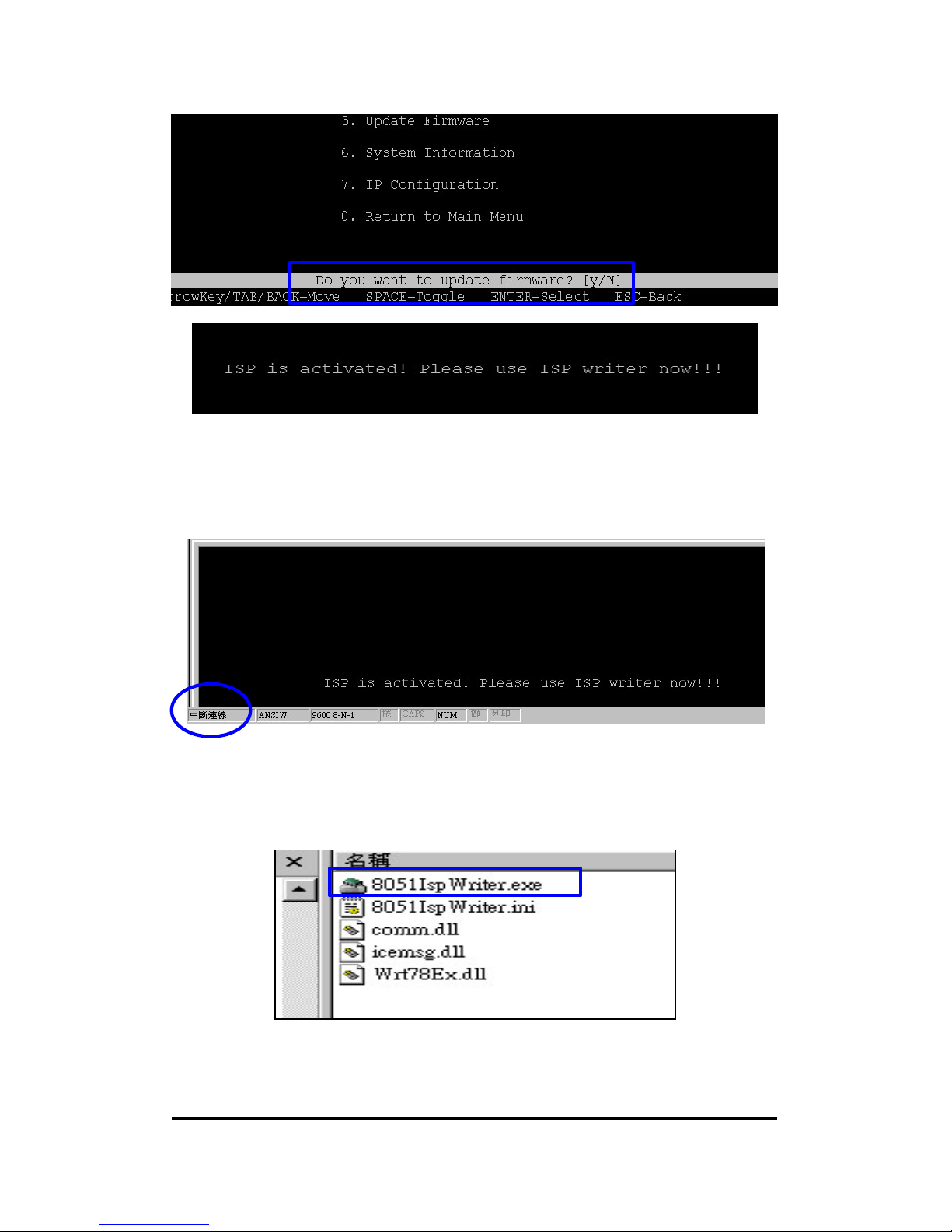
3. Select item no. 5 of update firmware and press enter key, that you will see the
process message by bottom page. Select YES and go to firmware upgrade mode.
Page 42
24+2G Web Smart-switch User Manual
Revision 1.0- 42
4. In this page, that you need to terminate the connection mode as below show figure.
Since switch product supports ONLY one connection and in order to use firrware
upgrade utility that this process is required.
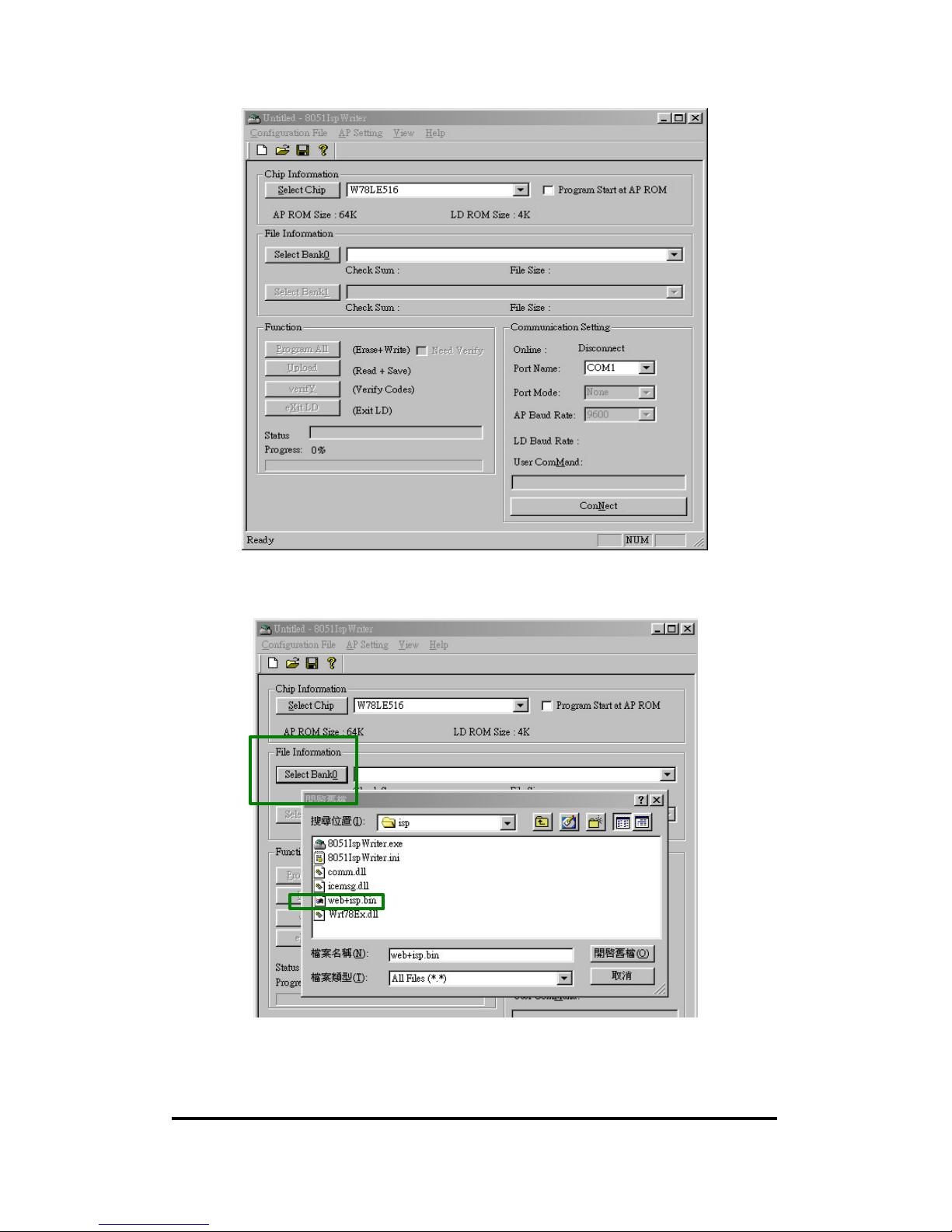
5. Please click on firmware upgrade utility of 8051ISP Writer.exe and retrieve the file
of image.bin at same time ( target upgrade firmware ).
Page 43
24+2G Web Smart-switch User Manual
Revision 1.0- 43
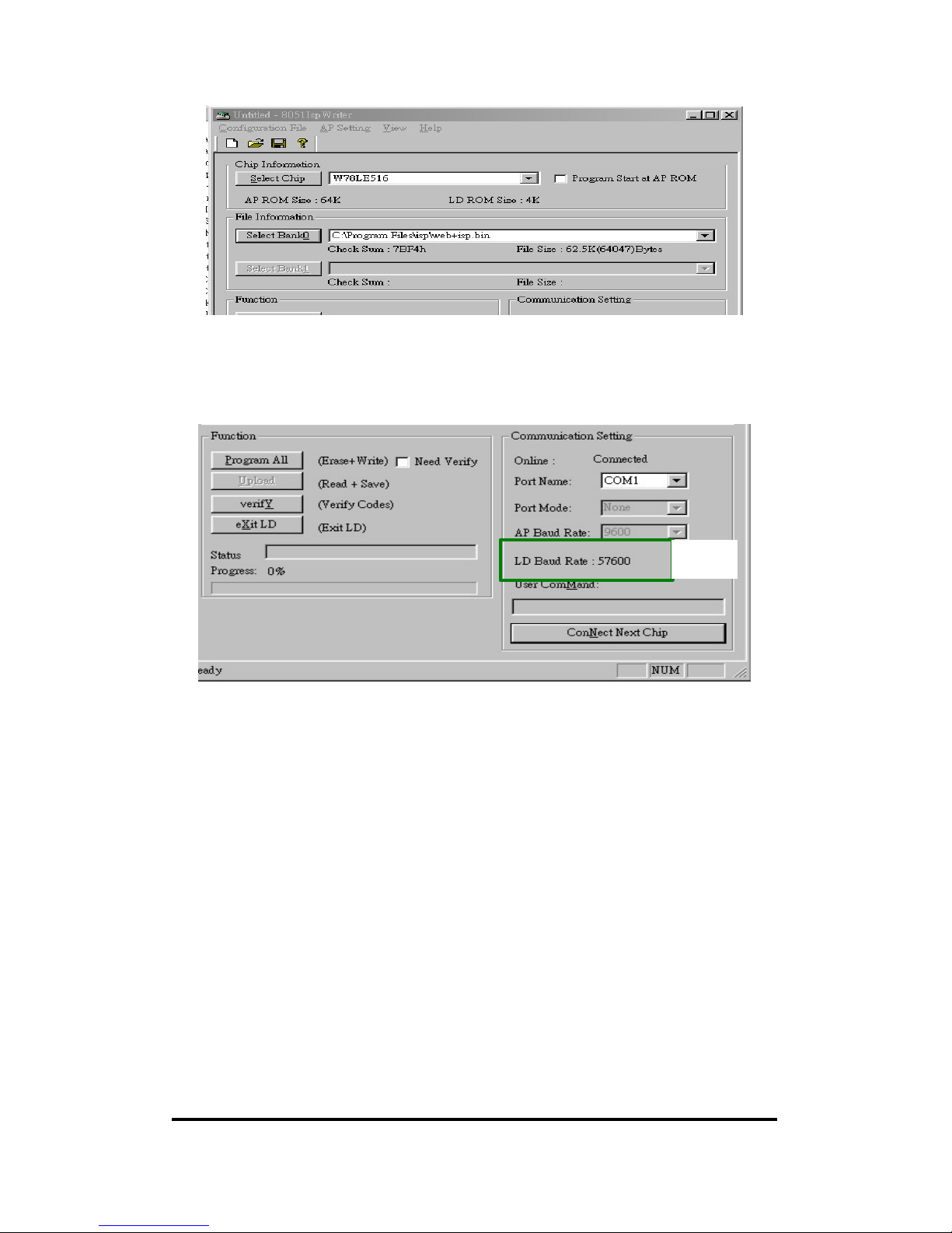
6. Please select image.bin by icon of Select BankQ as below figure shown.
6.1
6.2
Page 44
24+2G Web Smart-switch User Manual
Revision 1.0- 44
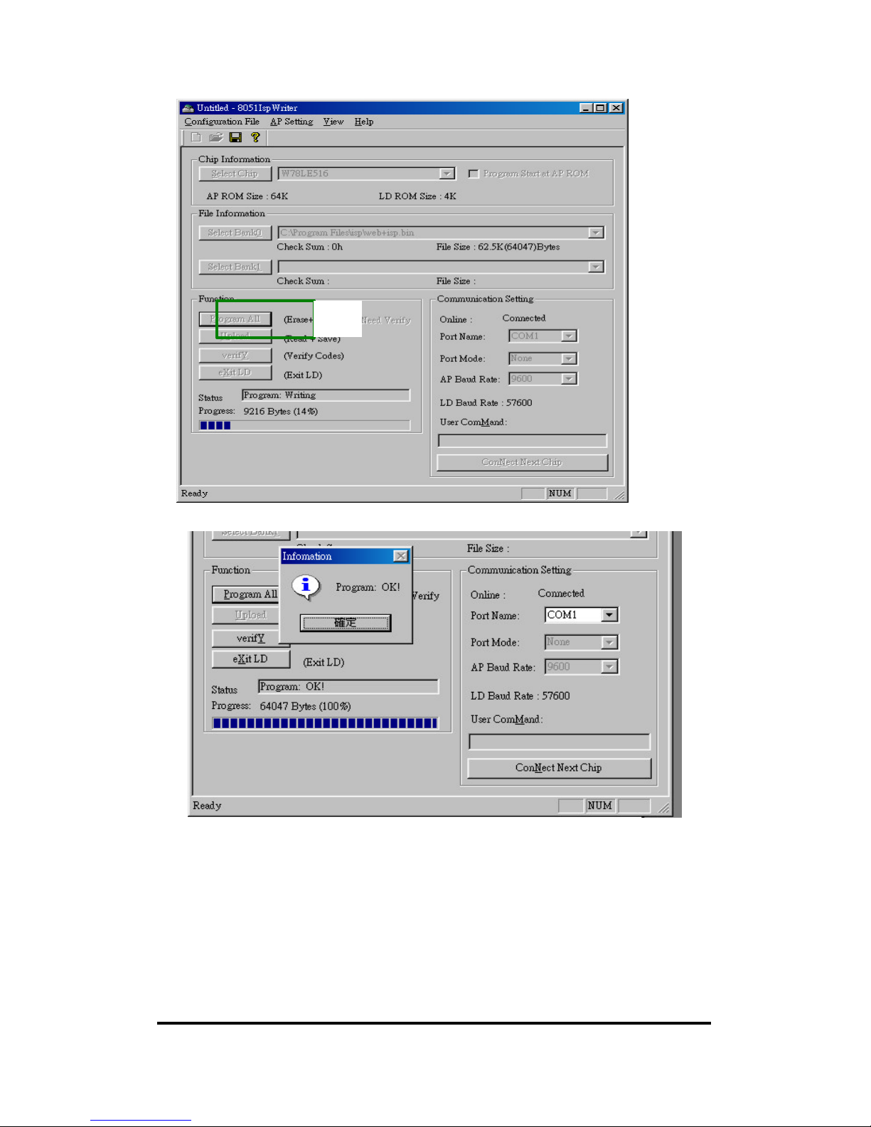
7. When the target firmware was selected that you need to click on ConNect icon as
below figure shown, then you will be read about the baud rate of 57600 as below
figure shown..
8. Please click on program all for firmware upgrade, when the firmware is upgraded
there is a message about process completion .
7.1
Page 45
24+2G Web Smart-switch User Manual
Revision 1.0- 45
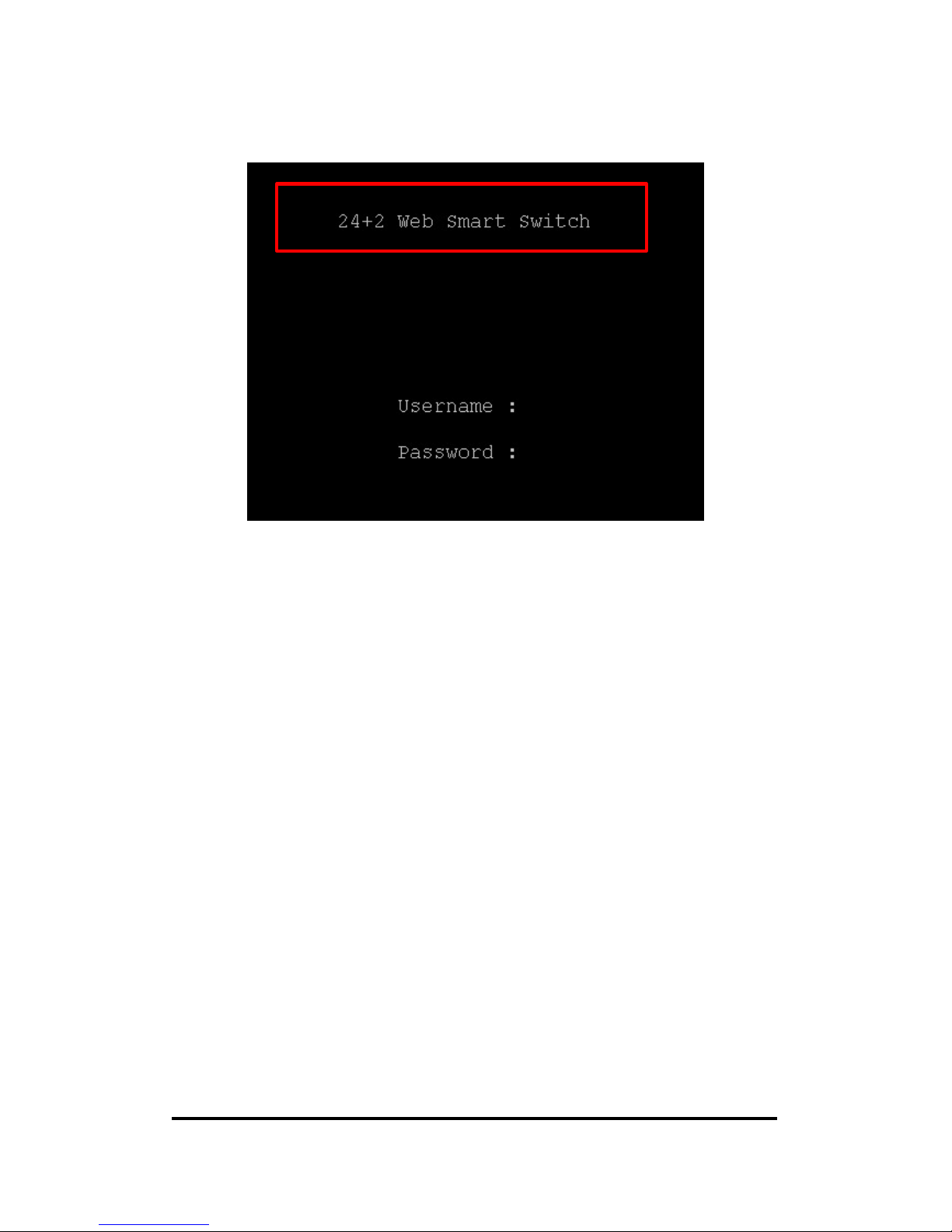
9. To identify the firmware upgrade process that you need to re-boot switch in order
to verify the product model whether has been changed to 24+2 Web Smart Switch.
8.1
Page 46
24+2G Web Smart-switch User Manual
Revision 1.0- 46
Below fighre shown the firmware was upgraded sucessfully.
 Loading...