

Page 1
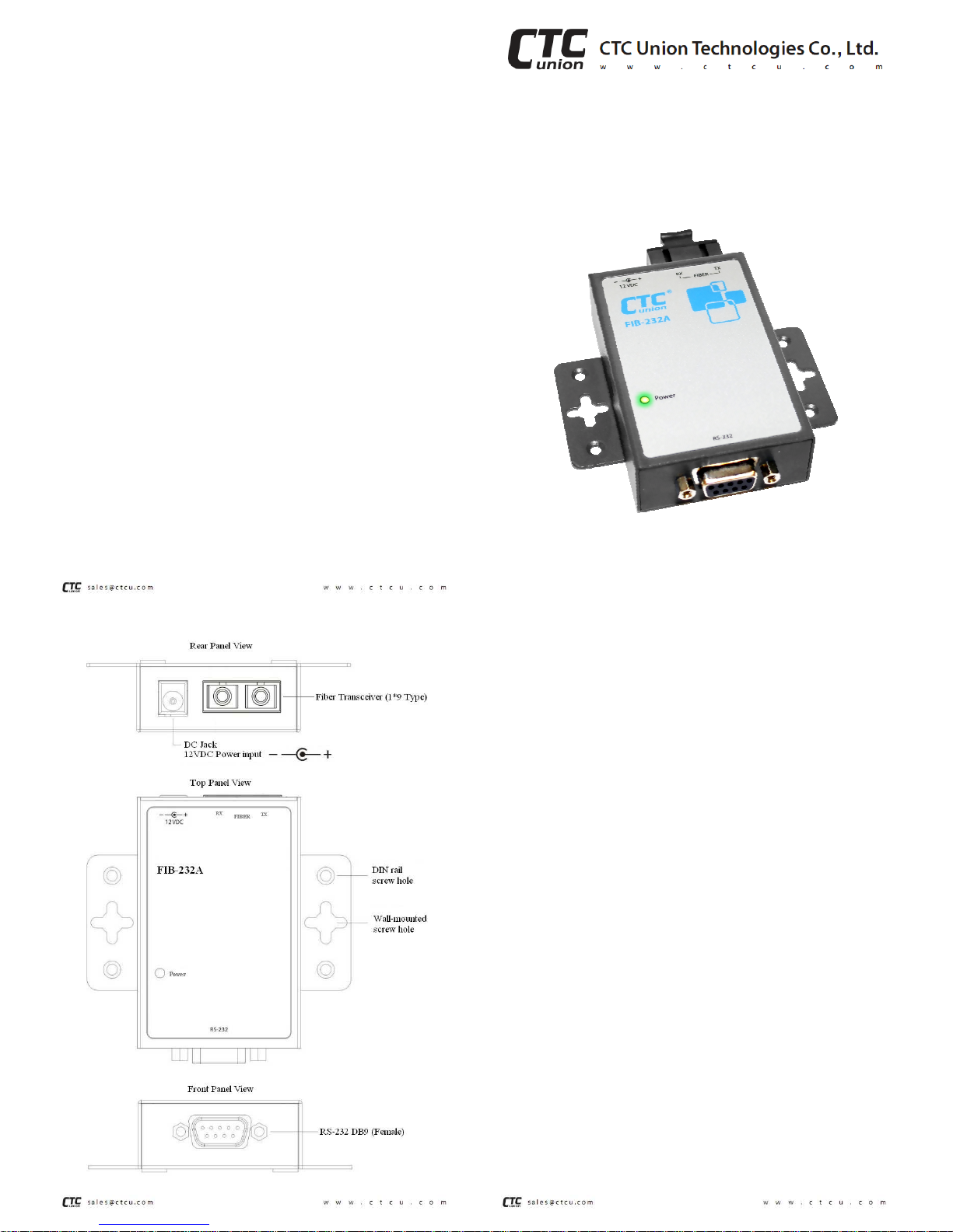
Description
FIB-232A is a compact, self-contained fiber interface
converter that provides for extension of the RS-232
communication standard over fiber media. FIB-232A
consumes power from an external 12VDC, 400mA, AC
switching power adapter. Depending on the model, FIB-
232A provides extension over multi-mode fiber cable up
to 2Km or single mode fiber up to 120Km. FIB-232A is
available with three of the industry’s leading standard
fiber connectors, ST, SC or FC type.
FIB-232A requires absolutely no configuration
whatsoever. Just connect the serial interfaces, attach the
optical cables and apply external power.
Features
• Compact size
• Wall mount, DIN rail mount option
• ST or SC type connectors.
• Multi-mode 62.5/125µm fiber cable up to 2Km.
• Single-mode 9/125µm fiber cable up to 120Km.
• FULL duplex
• Power budget: 11dB to 35dB. (transceiver dependant)
• RS-232: DB9 Female (DCE).
• Speed: DC ~ 230,400bps.
• BER: <10
-10
.
• Power LED indication
User Guide
EIA-232 to Fiber Media Converter
• FIB-232A-ST
• FIB-232A-SC
• FIB-232A-FC
Specifications
Standards EIA 232E, CCITT V.28
Mode Asynchronous DCE
Connector DB9 Female
Data Rate DC to 230.4Kbps
Input logic low Max. 0.8V threshold
Input logic high Min. 2.0V threshold
Receiver range -30V to +30V
Transmitter output -5V to +5V
Output resistance 300Ω
Fiber Port 155M Fiber Transceiver, 1x9 Type
Power Adapter DC12V, 400mA
Consumption <100mA (~1 watt)
Physical
Dimensions 50mm x 95mm x 22mm WxLxH
(2in x 3 3/4in x 7/8in)
Weight 90 grams net
(3 oz. US)
Environment
Operation 0 ~ 50°C (32~122°F), 20 ~ 95% RH
Storage -20 ~ 80°C (-4~176°F), < 95% RH
V1.0
Page 2
Installation
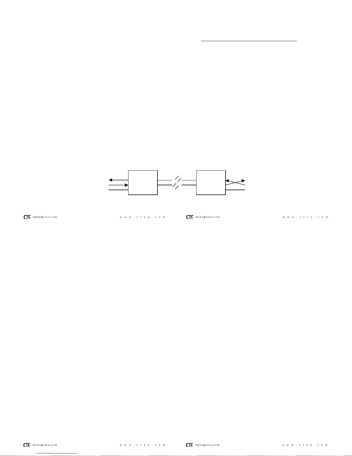
FIB-232A must be used in pairs. Connect the fiber cable
between the Fiber Media Converters. Make sure the fiber Tx of
one converter connects to the fiber Rx of the opposite converter.
The DB9 Female connector provides the RS-232 connection.
Wired as a DCE (Data Communications Equipment) device, the
FIB-232A uses a simple 3-wire scheme of TD, RD and Signal
Ground (SG). For a DCE device, the RD signal (pin 2) is an
output while the TD signal (pin 3) is an input. All other
handshaking signals are floating.
When connecting to a computer’s COM port, use a one to one
serial cable. When connecting to other DCE equipment, cross
over the TD and RD signals.
Install the fiber converter with the AC power adapter provided
(+12VDC, 400mA) and connect the adapter to an AC outlet.
Typical RS-232 Extension Application
Pin Assignment
RS-232 pin on DB9 Female
Pin No. Direction Function
1 NC
2 OUT RD
3 IN TD
4 NC
5 --- SG
6 NC
7 NC
8 NC
9 NC
DCE
TD
RD
SG
PC COM(DTE)
RD
TD
SG
RS-232
RS-232
RD Rx
TD Tx
SG
Tx TD
Rx RD
SG
Fiber
Model Summary
FIB-232A/STxxx ST connector
FIB-232A/SCxxx SC connector
FIB-232A/FCxxx FC connector
Where xxx =
002 2km MM 1310nm 11dB
015 15km SM 1310nm 18dB
030 30km SM 1310nm 20dB
050 50km SM 1310nm 28dB
080 80km SM 1550nm 29dB
120 120km SM 1550nm 35dB
Technical Contact
CTC Union Technologies Co., Ltd.
Far Eastern Vienna Technology Center
(Neihu Technology Park)
8F, No. 60 Zhouzi St.
Neihu, Taipei, 114 Taiwan
Phone: +886-2-2659-1021
FAX: +886-2-2799-1355
Version 1.0 First Release, May 3, 2012
This document is the current official release manual. Please check CTC Union's website
for any updated manual or contact us by E-mail at [email protected]. Please address any
comments for improving this manual or to point out omissions or errors to
[email protected]. For technical support for t his product or oth er CTC Union
products, contact our support staff at [email protected]. Thank you.
Warning
This equipment has been tested and found to comply with the
limits for a Class A digital device, pursuant to Part 15 of the FCC
Rules. These limits are designed to provide reasonable protection
against harmful interference when the equipment is operated in a
commercial environment. This equipment generates, uses, and
can radiate radio frequency energy and if not installed and used
in accordance with the instruction manual may cause harmful
interference in which case the user will be required to correct the
interference at his own expense. NOTICE: (1) The changes or
modifications not expressively approved by the party responsible
for compliance could void the user's authority to operate the
equipment. (2) Shielded interface cables and AC power cord, if
any, must be used in order to comply with the emission limits.
CISPR PUB.22 Class A COMPLIANCE:
This device complies with EMC directive of the European
Community and meets or exceeds the following technical
standard. EN55022 -Limits and Methods of Measurement of
Radio Interference Characteristics of Information Technology
Equipment. This device complies with CISPR Class A. In a
domestic environment this product may cause radio interference
in which case the user may be required to take adequate
measures.
CE NOTICE
Marking by the symbol CE indicates compliance of this equipment
to the EMC directive of the European Community. Such marking
is indicative that this equipment meets or exceeds the following
technical standards: EN55022:1994/A1:1995/A2:1997 Class A
and EN61000-3-2:1995, EN61000-3-3:1995 and EN500821:1997
 Loading...