

Page 1
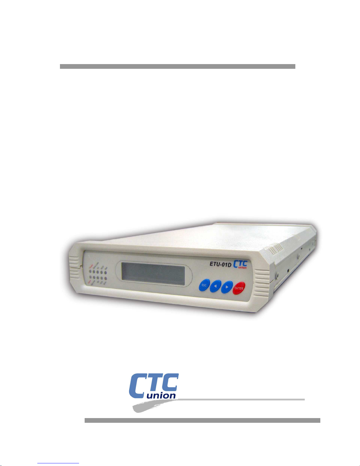
User Manual
ETU01-D
Single Port E1 Access Unit
with Fixed V.35 Datacom I/F
CTC Union Technologies Co., Ltd.
Page 2

Page 3

CTC Union Technologies Co., Ltd.
Far Eastern Vienna Technology Center (Neihu Technology Park)
8F, No. 60 Zhouzi St.
Neihu, Taipei 114
Taiwan
Tel: +886-2-26591021
Fax: +886-2-27991355
Email: [email protected]
URL: http://www.ctcu.com
ETU01-D User manual
English version 1.2 January 2007
User Manual for Single Port E1 Access Unit
Thank you for choosing our product.
Please read this manual carefully before using the ETU01-D.
This manual supports the following models:
ETU01-D 100-240 VAC model
ETU01-D –48V DC model
Copyright © 2006, CTC Union Technologies, Inc.
All rights reserved.
All specifications are subject to change without prior notice.
Page 4

Page 5

Table of Contents
Chapter 1. Introduction
1.1 Introduction........................................................................................................7
1.2 Functional Description......................................................................................7
1.3 Typical System Applications............................................................................8
1.4 E1 signal structure.............................................................................................9
1.5 ETU01-D Capabilities.....................................................................................10
1.6 TECHNICAL SPECIFICATIONS...............................................................12
Chapter 2. Installation
2.1 General..............................................................................................................15
2.2 Site Preparation...............................................................................................15
2.3 Mechanical Assembly......................................................................................15
2.4 Electrical Installation......................................................................................17
Chapter 3. Front Panel Operation
3.1 GENERAL........................................................................................................19
3.2 CONTROLS AND INDICATORS ...............................................................19
3.3 Menu Operation...............................................................................................20
Chapter 4. Control Port Operation
4.1 General..............................................................................................................31
4.2 Terminal Connection ......................................................................................31
4.3 Menu System Detail.........................................................................................32
Chapter 5. Loop Back and BERT Tests
5.1 Test Loops.........................................................................................................57
Appendix
Appendix A .............................................................................................................61
Technical Inquiry Form
Page 6

Table of Contents
Page 7

Chapter 1 Introduction
7
1.1 Introduction
The ETU01-D provides an economic access solution for Fractional E1 network
services. Single DTE device may be linked to the ETU01-D at combined data rates
of 64kbps to 2048kbps.
The ETU01-D supports local control and diagnostics via the front panel LCD and
a serial RS-232 craft port. This feature enables users to easily configure the unit,
execute the in-service diagnostics and monitor the network status.
1.2 Functional Description
The ETU01-D data channel support user-selectable transmission rates, which are
integer multiples of 64kbps, up to a maximum 2.048Mbps on twisted pair or coax
cable. The ETU01-D fully meets all of the E1 specifications including ITU G.703,
G.704, G.706, G.732, and G.823.
Multiple clock source selection provides maximum flexibility in connecting both
the E1 and user interfaces. The ETU01-D has the flexibility to meet the timing
requirements of various system configurations. The timing modes for the E1 link
and for the user channel are selected by the setting of configuration data via the front
panel LCD display, or terminal mode console port. The E1 link may be clocked
from the E1 recovered receive clock, from the user data port, or from the internal
oscillator.
The ETU01-D provide IDLE CODE mode, you can set any time slot and insert
the idle code with '00'-'FF', and the default code is '7F'.
The ETU01-D includes a BERT generator and receiver which may internally
connect to either E1 or data channel.
The ETU01-D is available in either AC or DC models. The models include AC
(100-240VAC) or DC (18-72VDC).
Page 8
Chapter 1 Introduction
8
1.3 Typical System Applications
General
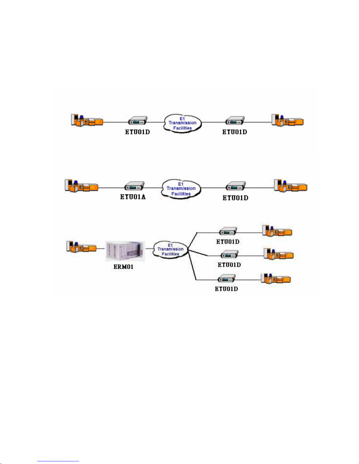
Figure 1-1: Example; Typical Application
In a typical application (Figure 1-1), the ETU01-D is used to connect the
synchronous data channel of a single router and the local and remote LANs over an
E1 line. The fractional E1 data service is based on the assumption that the combined
user data rate of all channel modules is equal to or is a fraction of the full available
E1 bandwidth, in multiples of 64K.
Page 9

Chapter 1 Introduction
9
1.4 E1 signal structure
The E1 line operates at a nominal rate of 2.048Mbps. The data transferred over
the E1 line is organized into frames, with each E1 frame containing 256 bits. The
256 bits are organized as 32 time slots of eight bits each and carry the data payload.
E1 transmissions utilize two main types of framing: Frame Alignment Signal
(FAS) and Multi-Frame Alignment Signal (MFAS). Framing is necessary in order
for equipment receiving the E1 signal to be able to identify and extract the
individual channels. PCM-30 (CAS) transmission systems use MFAS framing along
with FAS framing. PCM-31 (CCS) transmission systems use only FAS framing.
Frame Alignment Signal (FAS) The 2.048 Mbps frame consists of 32 individual
time slots (numbered 0-31). As described previously, each time slot consists of an
individual 64 Kbps channel of data. In the FAS format, time slot 0 of every other
frame is reserved for the frame alignment signal pattern. Alternate frames contain
the FAS Distant Alarm indication bit and others bits reserved for national and
international use.
Multi-Frame Alignment Signal (MFAS) MFAS framing uses Channel Associated
Signaling (CAS) to transmit the A/B/C/D bits signaling information for each of 30
channels. This method uses the 32 time slot frame for mat with time slot 0 dedicated
for the Frame Alignment Signal (FAS) and time slot 16 dedicated. For the MultiFrame Alignment Signal (MFAS) and the Channel Associated Signaling (CAS).
E1 line signal
The basic E1 line signal is coded using the Alternate Mark Inversion (AMI) or
HDB3 rule.
In the AMI format, "ones" are alternately transmitted as positive and negative
pulse, whereas "zeros" are transmitted as a zero voltage level. AMI is not used in
most 2.048 Mbps transmissions because synchronization loss occurs during long
strings of data zeros.
In the HDB3 format, a string of four consecutive zeros is replaced with a
substitute string of pulses containing an intentional bipolar violation. The HDB3
code substitutions provide high pulse density so that the receiving equipment is able
to maintain synchronization with the received signal.
Page 10

Chapter 1 Introduction
10
1.5 ETU01-D Capabilities
E1 link line coding
The ETU01-D supports two E1 line codes:
AMI coding.
HDB3 coding.
E1 framing formats
The ETU01-D supports three formats:
Unframed format. (in Unframed, only Data port 1 is supported)
FAS (CCS, PCM-31) format. (TS0 reserved)
MFAS (CAS, PCM-30) format. (TS0 and TS16 reserved)
User data channel rates
The ETU01-D supports each user data channel rates which are a multiple of
64kbps. For maximum flexibility, the ETU01-D supports combined data rates up to
2.048Mbps.The ETU01-D supports flexible time slot assignment, allowing the user
to freely specify the selection of time slots, in sequence or randomly, for each data
channel.
User data channel interface
The ETU01-D has a single user data channel interface and it is a fixed type of
user data channel interface: V.35.
System Timing Considerations
The ETU01-D has the flexibility to meet the timing requirements of various
system configurations. The timing mode for the E1 link and for the user channel are
selected by the setting of configuration data via the front panel LCD display.
E1 link timing
The ETU01-D E1 link receive path always operates on the receive clock. The
ETU01-D recovers the receive clock from the received E1 link data signal. The
source of the ETU01-D E1 link transmit clock can be selected by the user.
Page 11

Chapter 1 Introduction
11
The following E1 link transmit timing modes are available.
Loop back timing
The ETU01-D E1 link transmit clock is locked to the recovered receive
clock (E1 link). This is usually the timing mode selected for network operation.
Internal timing
The ETU01-D E1 link transmit clock is derived from the internal clock
oscillator. This timing mode is necessary in point-to-point applications over leased
line. In this case, one ETU01-D must use the internal oscillator, and the others must
operate from the recovered clock.
External timing
The ETU01-D E1 link transmit clock is locked to the clock signal
provided by the user DCE connected to the user's data channel. When the data
channel is used as the clock source, the data channel must use clock timing mode 2
(DTE).
User data channel timing
The ETU01-D has two user data channel clocking modes:
Clock mode 1 (DCE)
The ETU01-D data channel operates as a DCE providing the transmit
and receive clocks (recovered timing) to the data terminal equipment connected to
the user channel. The clocks are locked to the master timing.
Clock mode 2 (DTE)
The ETU01-D data channel operates as a DTE (crossover cable
required) and accepts both transmit clock and receive clock (both from the ETC pin)
from the user DCE equipment.
Page 12
Chapter 1 Introduction
12
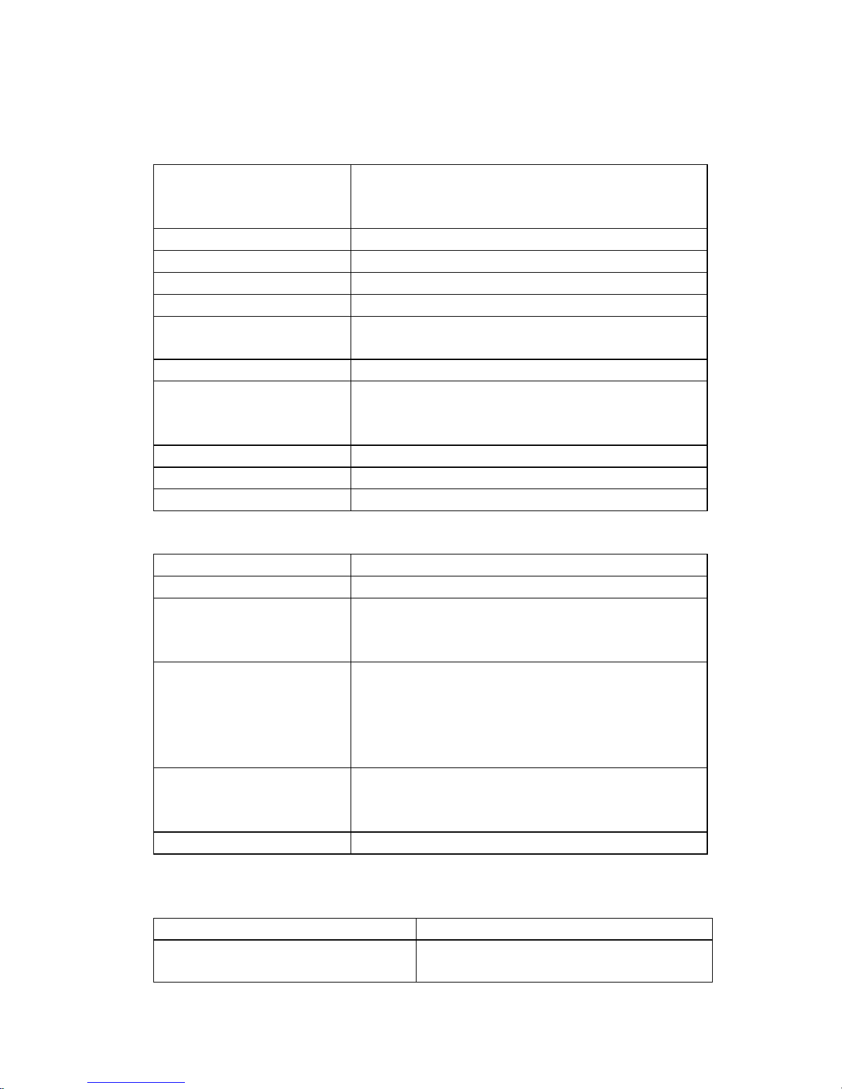
1.6 TECHNICAL SPECIFICATIONS
Main E1
Framing
-Unframed/Framed
-FAS (PCM31) / -FAS+CAS (PCM30)
-CRC4 ON/OFF
Bit Rate 2.048 Mbps
Line Code -AMI / -HDB3
Line Impedance -Unbalanced 75 ohms / -Balanced 120 ohms
Relative Receive Level 0 to -43dB
"Pulse" Amplitude
-Nominal 2.37V+/-10% for 75 ohms
-Nominal 3.00V+/-10% for 120 ohms
"Zero" Amplitude
0.1V
Tx Frequency Tracking
Internal / Loop back /
External Timing
+/-30 ppm, +/-50 ppm, +/-100 ppm
Jitter Performance According to ITU-T G.823
Complies With ITU-T G.703, G.704, G.706 and G.732
Interface Connectors -RJ45 / -BNC
User Data Channel
Interface Types -V.35
Interface Connectors V.35 25 pin, D-type Female
Data Rate
N*64kbps
Where N equal 1 to 31 in CCS
And N equal 1 to 30 in CAS
Clock Modes -Clock Mode 1 (DCE): Receive and transmit
clock (recovered) to the Synchronous DTE
-Clock Mode 2 (DTE): Receive and transmit
clock from the synchronous DCE (all from
ETC pin).
Control Signals -CTS constantly ON or follows RTS
-DSR constantly ON, except during test loops
-DCD constantly ON, except during signal loss
Time slot allocation User defined, randomly assignable
Setup/Configuration
LCD 2 rows of 16 characters
Pushbutton Switches -ESC / -Left Arrow
-Right Arrow / -Enter
Page 13

Chapter 1 Introduction
13
Front Panel
Figure1-2 ETU01-D Front Panel
LED indicators
No#. LED Description Remark
1 Power Green light ON: Normal working status
2
Alarm
Green light ON: Receive E1 Alarm ( AIS,
RAI, MRAI)
3 SYN Loss Red light ON : SYNC Loss
4 SIG Loss Red light ON : Signal Loss
5
TD of
Datacom
1) Yellow light ON : Signal from DTE is "1"
2) Yellow light OFF : Signal from DTE is "0"
3) Yellow light FLASH : Signal from DTE is
"1" and "0"
6
RD of
Datacom
1) Yellow light ON : Signal from DTE is "1"
2) Yellow light OFF : Signal from DTE is "0"
3) Yellow light FLASH : Signal from DTE is
"1" and "0"
7 DCD
1) Green light OFF : DCD Off
2) Green light ON : DCD On
8
RTS 1) Green light ON : RTS from DTE is ON
2) Green light OFF : RTS from DTE is OFF
9 Test 1) Red light ON : Enables Loop Back function
2) Right light OFF : disables Loop Back
function
10 Error 1) Red light ON : BERT bits Error
2) Red light OFF : BERT bits no Error
Page 14

Chapter 1 Introduction
14
RS-232 CONSOLE port
Port interface: V.24/RS-232 asynchronous, DCE
Port connector: 9 pin D-type female
Data rate: 19200 bps
Data format: 1 start bit -8 data bits -No parity -1 stop bits
Alarm relay: Floating pair of NO and NC contacts
-Contact ratings: 1A at 30 VDC resistive or 0.5A at 125 VAC resistive
Physical
Height: 44 mm
Width: 195 mm
Depth: 245 mm
Weight: 925g net
Power supply
Voltage (AC model) 100 ~ 240 VAC
Voltage (DC model) 18 ~ 72 VDC
Frequency 47 to 63 Hz for AC power
Power consumption 15 VA
Environment
Temperature 0-50C / 32-122F
Humidity 0 to 90% non-condensing
Page 15
Chapter 2 Installation
15
2.1 General
This chapter provides detailed instructions for mechanical installation of the
ETU01-D. Following the completion of installation, please refer to Chapter 3 for
front panel operating information and Chapter 4 for console port operating
information.
2.2 Site Preparation
Install the ETU01-D within reach of an easily accessible grounded AC outlet. The
outlet should be capable of furnishing 100 to 240 VAC. Allow at least 10cm (4 inch)
clearance at the rear of the ETU01-D for signal lines and interface cables.
2.3 Mechanical Assembly
The ETU01-D is designed for tabletop, shelf or rack mount installation, and
except for rack mount installation, is delivered completely assembled. Rack
mounted applications require installation of additional rack mounting brackets. No
provisions are made for bolting the ETU01-D to the tabletop.
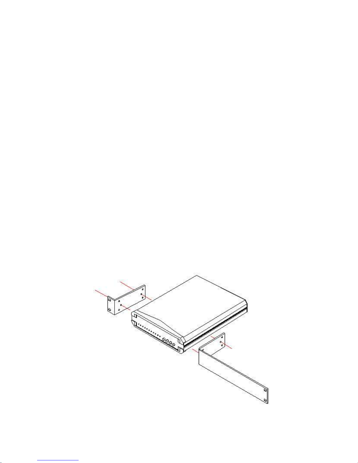
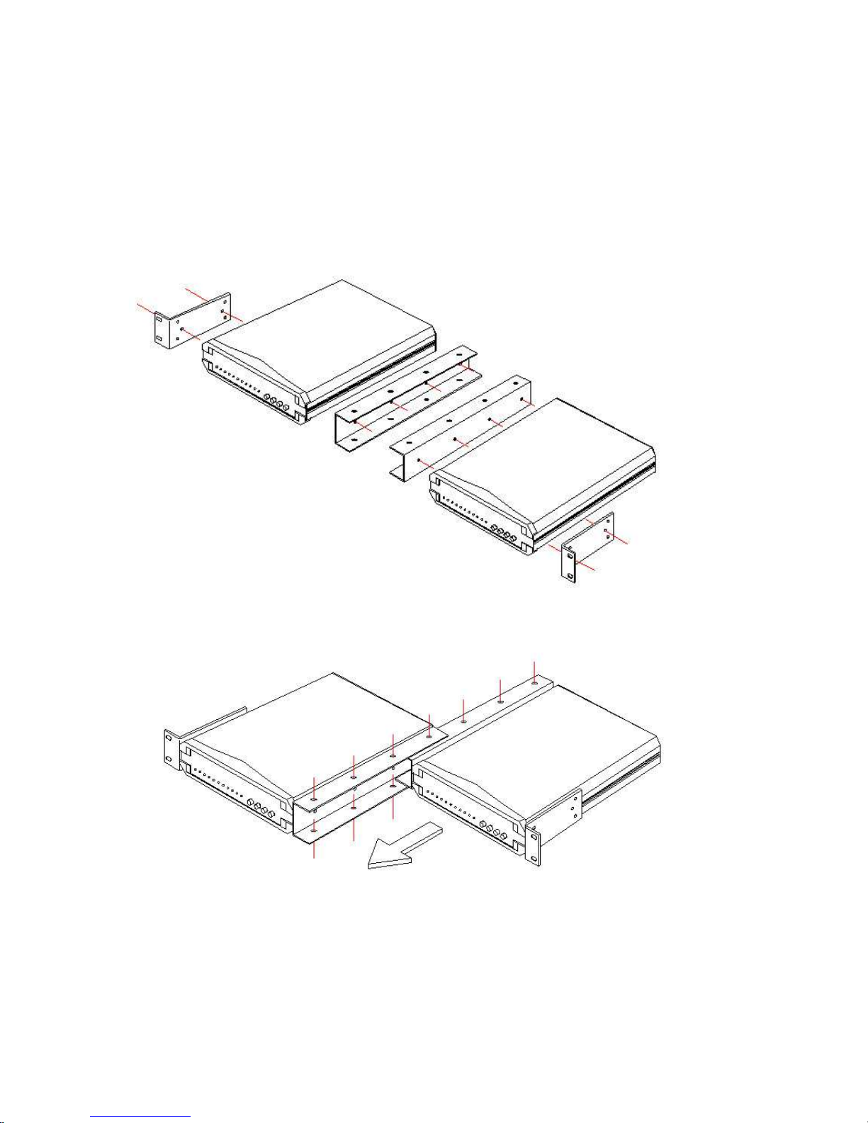
All Standalone/Rack Series units have the option of adding standard EIA 19" or
23" rack mount capability. Two rack mount options provide for either mounting a
single unit (half space) in a rack or for mounting two units in tandem (full space). In
either situation, one standard rack unit space is required. Each rack mount kit
provides all the necessary hardware for a complete installation.
Figure C-1: Rack Mount Installation, ETU01-SS.
Figure 2-1: Single Unit Mounting
Page 16
Chapter 2 Installation
16
In single unit installations, the unit may be placed in the left or right side position
simply by reversing the rack mounting "ears". The kit includes, one (1) short and
one (1) long rack adapter, four (4) 3x8mm self-tapping screws, and four (4) #1224x0.5" screws.
In order to save rack mount space, units may be mounted in tandem. Please refer
to the following drawing examples for this application.
Figure 2-2: Tandem Units Mounting (Exploded)
Figure 2-3: Tandem Units Mounting Detail
The tandem kit includes two (2) rack mount adapters, one (1) each of
inner and outer central mounting adapters, twenty (20) 3x8mm selftapping screws, and four (4) #12-24x0.5" screws.
Page 17

Chapter 2 Installation
17
2.4 Electrical Installation
2-4-1. Power connection
AC power is supplied to the ETU01-D through a "Mickey Mouse" type plug. The
ETU01-D should always be grounded through the protective earth lead of the power
cable.
2-4-2. Rear panel connectors
The data channel interfaces is fixed on the rear panel of the ETU01-D (Refer to
Figure 2-4 & 2-5 ) and consist of MB34pin connector for V.35. One RJ-45
(balanced type) interface and one pair of BNC (unbalanced type) Coax connectors
are available for the E1. The last connector is a DB9pin connector for the terminal
mode console port.
Figure 2-4 ETU01-D rear panel (AC model)
Figure 2-5 ETU01-D rear panel (DC model)
Page 18

Chapter 2 Installation
18
E1 Line side
BNC coax connector
One BNC coax pair of connectors marked RX and TX, provide unbalanced
75 Ohm connections for the E1 lines.
RJ-45 INTERFACE
A single RJ-45 connector marked E1, provide balanced 120 Ohm.
The pin assignments for RJ-45 connectors are as follows:
1 RTIP (Receive data in)
2 RRING (Receive data in)
4 TTIP (Transmit data out)
5 TRING (Transmit data out)
Note: This follows the USOC RJ-48C standard.
Page 19
Chapter 3 Front Panel Operation
19
3.1 GENERAL
This chapter describes the ETU01-D controls and indicators, and explains
operation setup procedures using the front panel LCD and menu keys. Installation
procedures (in Chapter 2) must be completed and checked before attempting to
operate the ETU01-D.
Note: To ensure stability, we recommend that after setting all the parameters and
doing a "save & reboot”.
3.2 CONTROLS AND INDICATORS
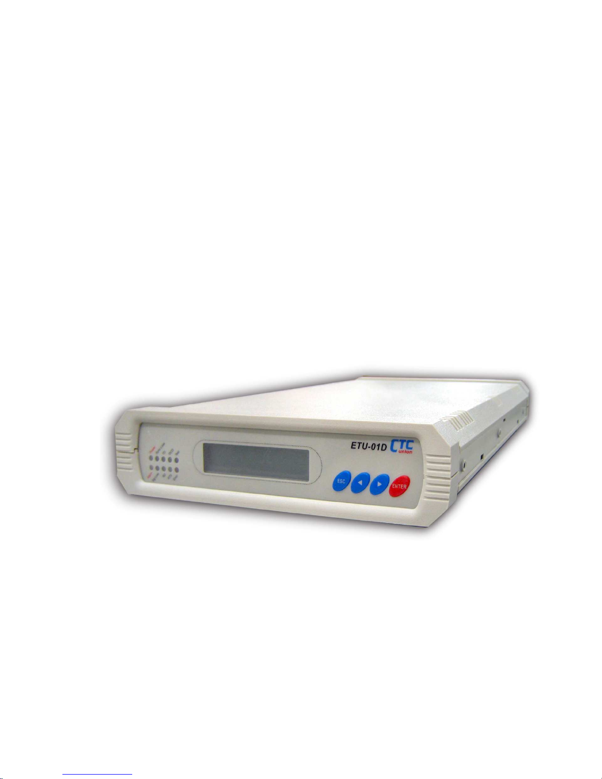
All controls (push-button switches), LCD display and LED indicators are located
on the ETU01-D front panel. The momentary on pushbutton switches are used to
activate menu selections and select parameter settings.
Figure 3-1: ETU01-D Front Panel
Use the 'LEFT' and 'RIGHT' function keys to browse the menus and select
parameters.
Use the 'ESC' function key to return to a previous menu or to abandon setup.
Use the 'Enter' function key to set a parameter of a selection or to enter a sub-menu.
Page 20
Chapter 3 Front Panel Operation
20
3.3 Menu Operation
3.3.1 Top Level Menus
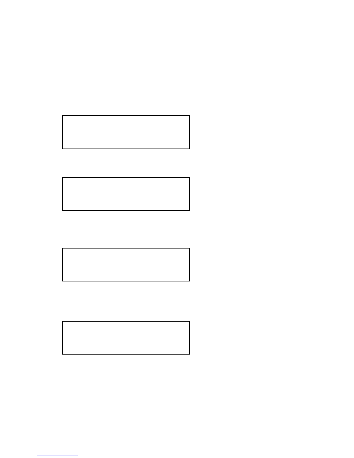
The following are the 8 top level Menus. Press an arrow key (LEFT or RIGHT) to
select another top level Menu or press ENTER to reach a sub menu.
When powered on, the ETU01-D will work under the last saved setting. Press
ESC to stop the running, and the LCD will display:
Set the default system parameter, save the present parameter, reset the system,
and choose the system clock.
Set the Line code, interface and distance, transmit buffer, receive buffer,
Frame type, and idle code for E1 link.
Assign the E1 timeslots to the Data Channels link.
RUN ON
>>>>>>>>>>>>>>>>
< SYSTEM >
PARAMETER
< E1 LINK >
PARAMETER
< TIME SLOT >
MAPPING
For normal transmissions, the
unit must be in 'RUN' mode.
Page 21
Chapter 3 Front Panel Operation
21
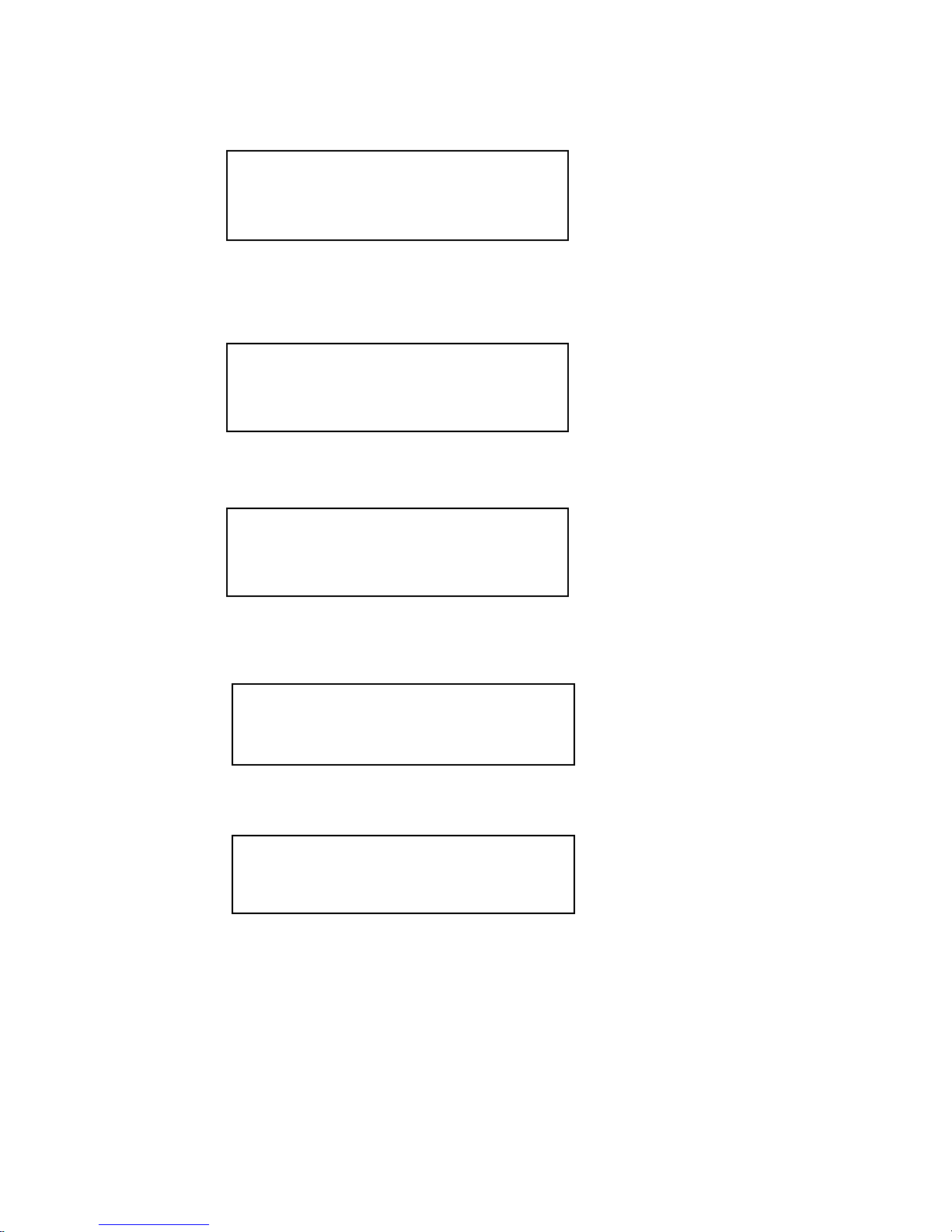
Data Port informational screen and settings for Clock Mode, Clock Polarity
and Handshaking.
Enable main link, or data channel Loop back.
Enable BERT, select channel and select pattern.
Enable display the system date and time.
Enable display the alarm records which been stored in the buffer or delete all the
record
< LOOPBACK >
PARAMETER
< DATA PORT >
PARAMETER
< BERT TEST >
PARAMETER
< DATE & TIME >
DISPLY & SET
< ALARM BUFFER >
DISPLY
Page 22
Chapter 3 Front Panel Operation
22
Enable display all the parameter performance..
Exit the configuration and run the ETU01-D.
3.3.2 System Parameter Detail
The following screens show the setup screens under the System Parameter Main
Screen.
Press ENTER; the SYSTEM PARAMETER sub-menu will be displayed.You can
modify all the system parameters, save all changes, or reset the unit back to the
default settings.
Press ENTER, the ETU01-D will work in the default mode.
DEFAULT
SAVE & REBOOT
SYSTEM PARAMETER
< EXIT CONFIG >
****************
< PERFORMANCE >
Monitor
Page 23

Chapter 3 Front Panel Operation
23
Press ENTER, the ETU01-D will store all the parameters as current settings
and then reboot. The next time the ETU01-D is powered on, all the parameters
used will be those that were previously saved.
NOTE: Remember to save the parameters if you want to commit the
ETU01-D with the current parameters. If not, the ETU01-D will resume all
the parameters from the last saved settings when it is powered on the next time.
When pressing ENTER here, the system will reply with Y/N:[N]. Press
ENTER again and the system will show Y/N:[Y] and then reboot. Otherwise,
press ESC to leave without rebooting the system.
Press ENTER to set the system clock: Internal/External(Data Port)/Recovery(E1).
In a typical point-to-point application, the local unit will set the clock source to the
built-in oscillator (Internal) and the remote unit will recover clock from the received
E1 (Recovery).
If the clock source comes from connected DCE equipment, such as a multiplexer or
another modem, a crossover cable may be employed to send the connected DCE's
clock from the RC to the ETU01-D's ETC and the clock setting will be set to the
data port (External).
REBOOT SYSTEM
< SYSTEM CLOCK >
INTERNAL
Page 24
Chapter 3 Front Panel Operation
24
3.3.3 Main E1 Parameter Detail
The following screens show the setup under the Main E1 Parameter.
Press ENTER and the MAIN E1 LINK sub-menu will be displayed. Main E1 Link
sets the LINE CODE, IMPEDANCE, LBO, TX JITTER, RX JITTER, FRAME type
and CRC mode for the mainE1 of the ETU01-D.
Use the arrow keys to browse the individual link parameters (frame, CRC, etc.)
Press ENTER on the parameter to select it with the cursors. Now use the arrow keys
to browse the available settings for that parameter. The following is a breakdown of
parameters and available settings:
LINE CODE: HDB3 or AMI, HDB3 default.
IMPEDANCE: 120ohm or 75ohm, 120ohm default.
LBO: SHORT or LONG, SHORT default.
TX JITTER: ON or OFF, OFF default.
RX JITTER: ON or OFF, OFF default.
FRAME: unframed, CCS or CAS, unframed default.
Technical Note: If E1 framing is set to "CAS", CRC-4 is always "ON". The
connected E1 equipment may either set its CRC4 "ON" or simply ignore CRC4.
This will not effect the normal transmission.
< MAIN E1 LINK >
PARAMETER
< LINE CODE >
[HDB3]
Page 25

Chapter 3 Front Panel Operation
25
3.3.4 Time Slot Mapping Detail
The following screens show the setup under the Time Slot Mapping.
Press ENTER
The E1 frame is shown with 32 timeslots, top row left to right are TS0-15, while the
bottom row displays the settings for TS16-31. Press arrows to move the cursor, use
ENTER to assign the timeslot as follows:
N: Not assigned
Y: Data Channel .
C: Insert idle code on E1 Tx side.
(Refer to E1 Link Parameter Detail to set the idle code.)
B: BERT test.
Note:
TS 00: Cannot be assigned in CCS or CAS mode of MAIN E1 LINK to
anything but Framing. BERT cannot be assigned to TS 00.
TS 16: Cannot be assigned in CAS mode to anything except Signalling. BERT
cannot be assigned to this timeslot in CAS and CCS mode.
< TIME SLOT >
MAPPING
NNNNNNNNNNNNNNNN
NNNNNNNNNNNNNNNN
Page 26
Chapter 3 Front Panel Operation
26
3.3.5 Data Port Parameter Detail
The following screens show the setup under the Data Port Parameter.
This screen shows the Channel interface type. Press ENTER and the Channel submenu will be displayed. It contains the Clock Select and Clock Polarity.
Press ENTER to Select: DCE/DTE
Press ENTER to select the Clock Polarity:
Type1: Tx pos Rx neg
Type2: Tx pos Rx pos
Type3: Tx neg Rx pos
Type4: Tx neg Rx neg
Tx: Transmit clock
Rx: Receive clock
Pos: Data sync at the clock rising edge.
Neg: Data sync at the clock falling edge.
Note: If all parameters are set correctly and the data port transmission fails, please
adjust clock polarity to correct the transmission.
< CLOCK SELECT >
[DCE]
< CLOCK POLARITY
Tx pos Rx neg
< DATA PORT >
PARAMETER
Page 27
Chapter 3 Front Panel Operation
27
3.3.6 Loop back Parameter Detail
The following screens show the setup under the Loop back Parameter. In order to
perform Remote Loop back functions, the E1 frame format must be CCS or CAS
mode. Remote loop back is not supported in unframed mode. In BERT mode, the
user may also perform loop back test functions.
Press ENTER
Use the arrow keys to browse the available options for loop back setting. By
default, all loop backs are off. The details are as follows:
Main Link: Loop back off, Local Analog, Local Digital, Local Payload, Remote
Analog, or Remote Payload.
Data Port : Loop back off, Local Analog, or Local Digital.
3.3.7 BERT Parameter Detail
The following screens show the setup under the BERT Parameter.
Press ENTER
< LOOPBACK >
PARAMETER
< FUNCTION >
[OFF]
< BERT TEST >
PARAMETER
〈 FUNCTION 〉
OFF
Page 28

Chapter 3 Front Panel Operation
28
Use the arrow keys to browse the available options for BERT setting. By
default, BERT is off. The details are as follows:
CHANNEL: MAIN -〉MAIN, or
PATTERN: 2e11-1 or 2e15-1.
For BERT TEST go to 3.3.4 "Time Slot Mapping Detail" and setup E1 frame to
"B" for BERT TEST
Note: BERT is not supported with Unframed E1. In BERT test, E1 should be in
framed mode (either CCS or CAS), patterns will pass through the time slots you
choose except TS0 and TS16.
3.3.8 Performance
Note: The BPV reception count in the ETU01-D is not sensitive. This means the
number of BPV transmitted may be different from the number of BPV received.
This is due to the E1 framer chip used in the ETU01-D and is beyond our control.
3.3.9 Exit Configuration
****IMPORTANT**** All of the configuration settings performed up until
now can be activated by exiting the configuration menu, back out to 'RUN.
However, unless the settings have been SAVED, they will be lost at next power
cycle. So, if these are the settings you wish to use permanently, be sure to go
back to the SYSTEM PARAMETER menu and do SAVE SET. Then exit the
configuration to the 'RUN' mode.
〈 EXIT CONFIG 〉
***************
Page 29
Chapter 3 Front Panel Operation
29
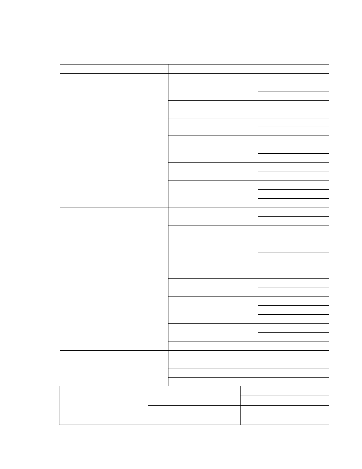
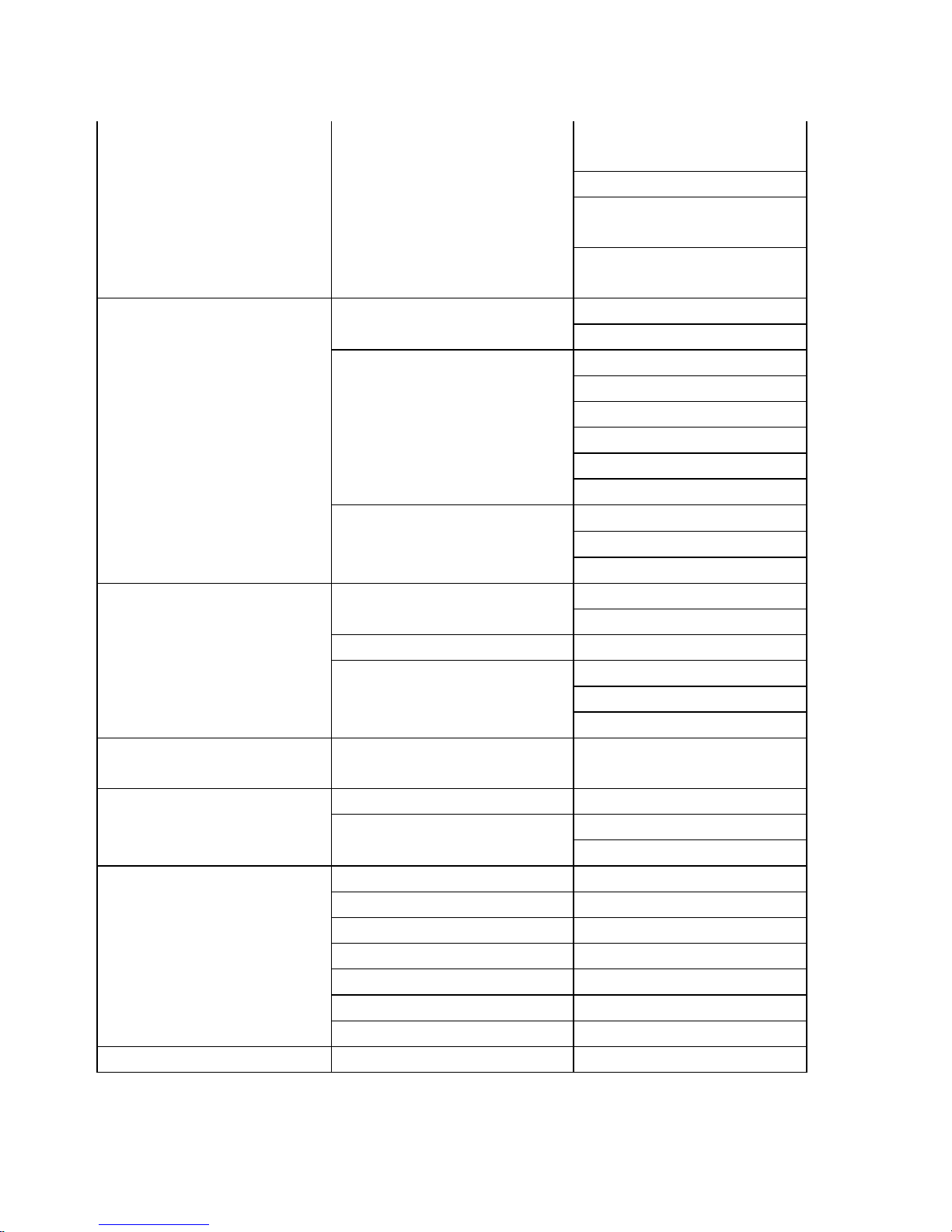
3.3.9 ETU01-D LCD menu breakdown
Main Menu
Sub
-
Menu
Menu Options
RUN ON
Y
DEFAULT
N
Y
SAVE & REBOOT
N
Y
REBOOT SYSTEM
N
INTERNAL
EXTERNAL
SYSTEM CLOCK
RECOVERY
SET PASSWORD
PASSWORD
CLEAR PASSWORD
OFF
ETU
01-D
SYSTEM PARAMETER
CONTROLLED
ERM
-01
HDB3
LINK CODE
AMI
75ohm
IMPEDANCE
120ohm
SHORT
LBO
LONG
ON
TX JITTER
OFF
ON
RX JITTER
OFF
Unframe
d
CCS
FRAME
CAS
ON
CRC-4
OFF
E1 LINK PARAMETER
IDLE CODE
N
Y
C
TIME SLOT MAPPING
B
DCE CLOCK SELECT
DTE
DATA PORT PARAMETER
CLOCK POLARITY TX POS
RX POS
Page 30
Chapter 3 Front Panel Operation
30
TX POS
RX NEG
TX NEG
RX POS
TX NEG
RX NEG
ON FUNCTION
OFF
CLOSE
LOCAL ANALOG
LOCAL DIGITAL
LOCAL PAYLOAD
REMOTE ANALOG
E1
REMOTE PAYLOAD
CLOSE
LOCAL ANALOG
LOOPBACK PARAMETER
DATA PORT
LOCAL DIGITAL
ON FUNCTION
OFF
CHANNEL E1 LINE
2E11-1
2E15-1
BERT TEST PARAMETER
PATTERN
QRSS
DATA&TIME
DISPLAY&SET
LOCAL ALARM BUFFER
Y
ALARM BUFFER DISPLAY
CLEAR ALARM BUFFER
N
BPV CNT
CRC-4
ERR SECS
UAS
LONG ES
LONG UAS
PERFORMANCE
MONITOR
CURR SEC
EXIT CONFIG
Page 31

Chapter 4 Control Port Operation
31
4.1 General
The ETU01-D Control Port (labeled RS-232) is a console terminal port designed
to facilitate setup of all parameters through the use of a standard text based terminal
or any terminal emulation program running on a Personal Computer.
Note: To ensure stability, we recommend that after setting all the parameters and
doing a "save & reboot”.
4.2 Terminal Connection
A notebook computer has become an invaluable tool of the Systems Engineer.
Connection to the computer is very straight forward. The only other hardware
required is a DB9-pin one-to-one, male to female cable. The ETU01-D acts as a
DCE to the PC's DTE communications port. A convenient application, provided
with the Microsoft Windows® 98/NT/2K/XP operating systems, is "Hyper
Terminal". Set the properties to match the ETU01-D control port defaults as
follows: Bits per Second=19200, Data bits=8, Parity=None, Stop bits=1, and Flow
Control=none. Make the appropriate connections, start the terminal application,
apply power to the ETU01-D, then press ENTER on the PC keyboard.
Note: When a terminal connection is made to the ETU01-D, the front panel LCD
will be locked out and display:
* CONTROL PORT *
CONNECTED >>>>>
Page 32
Chapter 4 Control Port Operation
32
4.3 Menu System Detail
The menu systems are displayed in the same order and with the same parameters
as those in the LCD display. The following section will detail actual displays with
descriptions of parameter settings via relevant key commands.
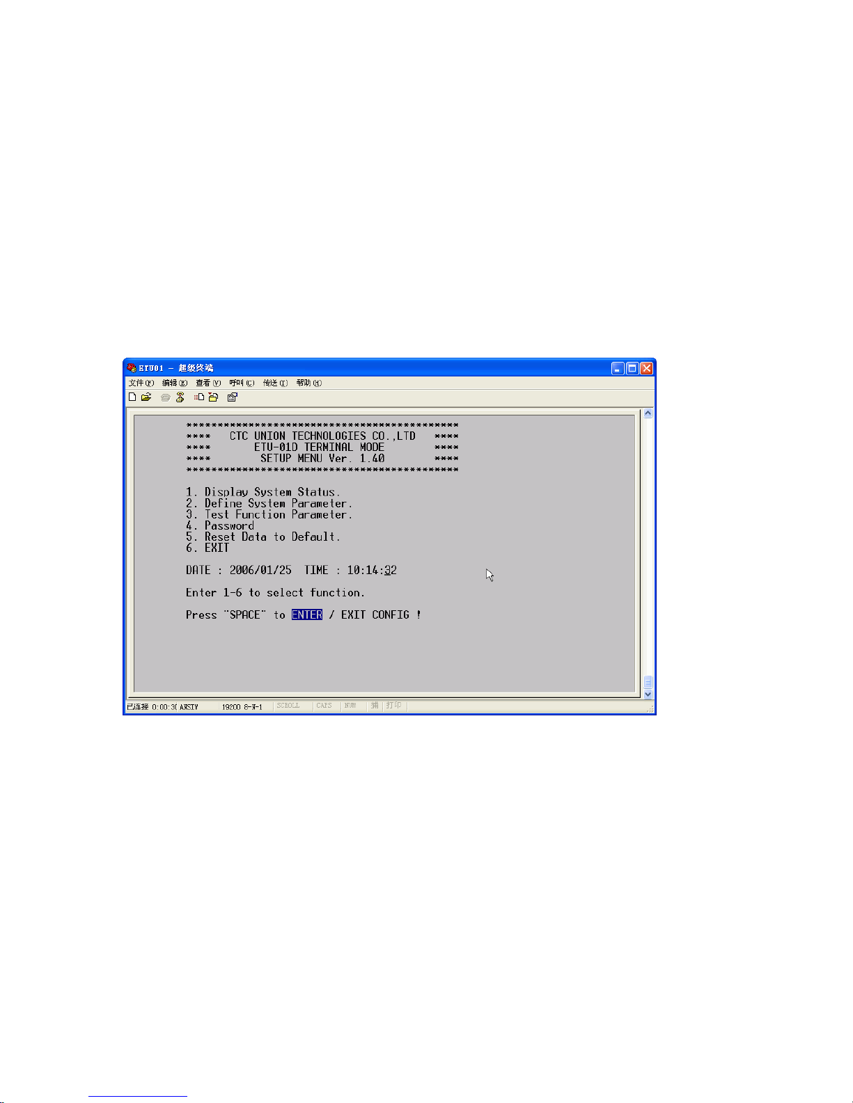
This is the first screen seen after connecting. Note that the first two items, Display
and Define deal with all the system settings. The Display item will browse settings
for viewing only, while under Define, all parameters may be both viewed and
changed.
Figure 4-2 Top menu
Page 33
Chapter 4 Control Port Operation
33
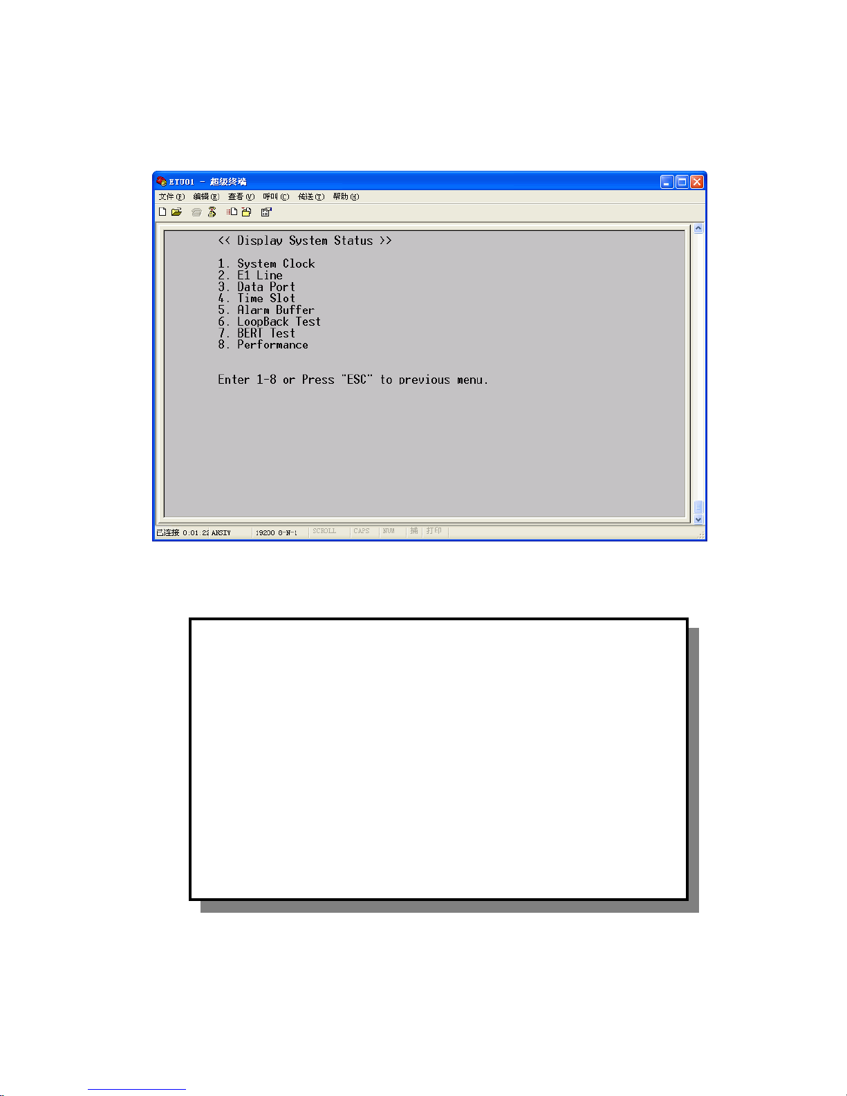
Enter 1 to Display System Status
Enter 1 to Display System Clock Parameter
The display shows that the System Clock Parameter is derived from the internal
oscillator. Exit this menu to the previous one, Press ESC.
<< Display System Clock Parameter >>
System Clock : INTERNAL
Press "ESC" to previous menu.
Page 34

Chapter 4 Control Port Operation
34
Enter 2 to Display E1 Parameter
The above display shows the settings for the E1 Line Code, E1 interface
impedance, LBO, Tx jitter, Rx jitter, Frame type, CRC setting and Idle code for the
E1 link. To return to the previous display, enter ESC.
<< Display E1 Parameter >>
Line Code : HDB3
Impedance : 75 ohm
LBO : SHORT
TX Jitter : OFF
RX Jitter : OFF
Frame : CCS
CRC-4 : OFF
Idle Code : 7FH
Press "ESC" to previous menu.
Page 35

Chapter 4 Control Port Operation
35
Enter 3 to Display Data Port Parameter
The Data Port display shows the current setting of the physical data port. The
clock setting and TC RC polarity are also shown in this information display. Press
ESC to return.
Enter 4 to Display the Time Slot Mapping
The Time Slot mapping display shows the assignments for all of the 32 timeslots
of the E1 frame. All timeslots 0-31 are shown with the assigned abbreviations shown
directly beneath. In CCS and CAS modes, never assign TS0. In CAS mode, never
assign TS16. To return to the previous display, enter ESC.
<< Display Time Slot Mapping >>
SLOT : 00 01 02 03 04 05 06 07
TYPE : N B B N N N N N
SLOT : 08 09 10 11 12 13 14 15
TYPE : N N N N N N N N
SLOT : 16 17 18 19 20 21 22 23
TYPE : N N N N N N N N
SLOT : 24 25 26 27 28 29 30 31
TYPE : N N N N N N C C
N: Time Slot not used Y: Data Port
C: E1 Idle Code B: Bert Time Slot
Press "ESC" to previous menu.
<< Display Data Port
Parameter >>
Type : V.35
Clock : DCE
Clock Polarity : TX Positive ; RX Negative
Press "ESC" to previous menu.
Page 36

Chapter 4 Control Port Operation
36
Enter 5 to Alarm BufferDisplay Menu
The function will allow system to display alarm records up to 40 records. Then
you can clear all the record by selecting the "3". Press ESC to return.
Enter 6 to Display Loop Back Test information
Enter ESC to return to the Display System Status menu.
<< Display LoopBack Test >>
Function : OFF
E1 : OFF
Data Port: OFF
Press "ESC" to previous menu.
<<
Alarm Buffer Display Menu
>>
1. Display Alarm Buffer
2. Display Remote Alarm Buffer
3. Clear Alarm Buffer
Enter 1-3 or Press "ESC" to previous menu.
Page 37
Chapter 4 Control Port Operation
37
Enter 7 to Display BERT Test information.
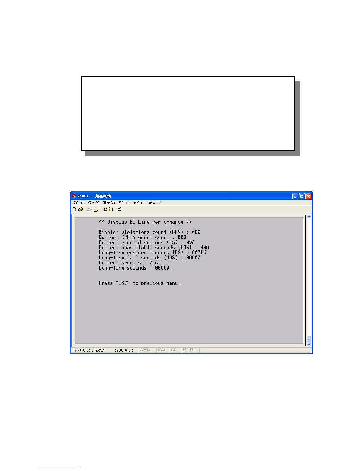
Enter 8 to Display E1 Line Performance.
Enter ESC to return to the Display System Status menu. Then press ESC again to go
to the very top menu display.
<< Display BERT Test >>
Function : OFF
Channel : E1 line
Pattern : 2E11-1
Press "ESC" to previous menu.
Page 38
Chapter 4 Control Port Operation
38
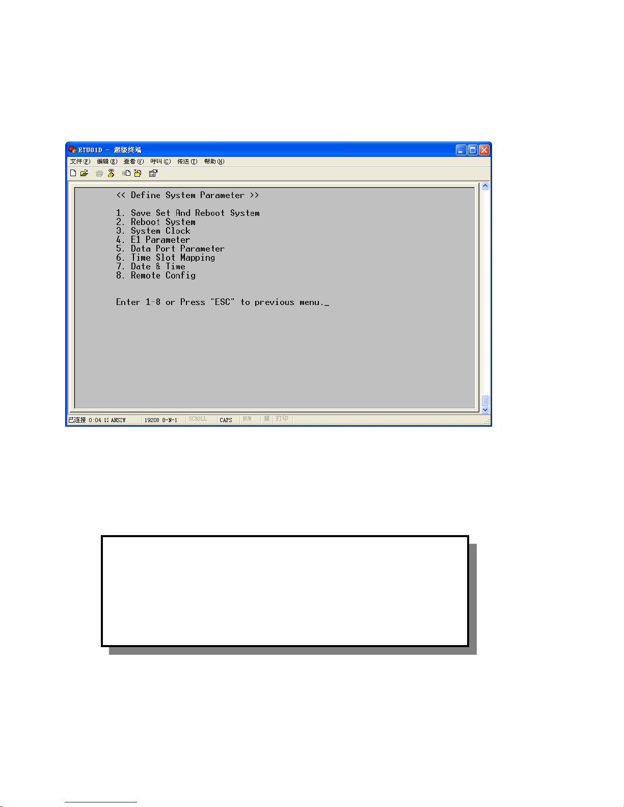
Now we will look at setting up the system parameters. To do this, enter 2.
The first selection of system parameters is the Save Set And Reboot System, and
the second selection is Reboot System. We recommend you do a 'Save Set And
Reboot System' after finishing the configuration. So let's enter 2 first.
****IMPORTANT**** You must do SAVE SET for configuration changes to be
remembered.
You need to wait about 10 seconds, then the screen will go blank. Press ENTER
to return to the start up screen. Press 2 to re-enter the Define Configuration page.
<< Re
boot
System >>
Press "ENTER" to confirm, "ESC" to previous menu.
Page 39

Chapter 4 Control Port Operation
39
To Define System Clock Parameter, press 3.
The display shows that the system clock is currently derived from the internal
oscillator. To change it, select one of the appropriate choices, one thru five or to exit
without changing press ESC.
In a typical point-to-point application, the local unit will set the clock source to
the built-in oscillator (Internal) and the remote unit will recover clock from the
received E1 (Recovery).
If the clock source comes from connected DCE equipment, such as a multiplexer
or another modem, a crossover cable may be employed to send the connected DCE's
clock from the RC to the ETU01-D's ETC and the clock setting will be set to the
data port (External).
Press 4 to Define E1 Parameter
<< Define System C
lock Parameter >>
System Clock : INTERNAL
1. INTERNAL
2. EXTERNAL
3. RECOVERY
Enter 1-3 or Press "ESC" to previous menu.
<< Define E1 Parameter >>
1. Line Code
2. Impedance
3. LBO
4. TX Jitter
5. RX Jitter
6. Frame
7. CRC-4
8. Idle Code
Enter 1-8 or Press "ESC" to previous menu.
Page 40

Chapter 4 Control Port Operation
40
Under the display, press 1-8 to define each parameter for the E1.
For example, to change the E1 Idle Code, press 8:
Enter the new idle code with the hex value 00-FF, or to exit, press ESC to the
Define E1 Parameter display, then press ESC again to the Define System Parameter
display.
Press 5 to Define Data Port Parameter
<< Define E1 Idle Code >>
Idle Code : 7FH
Press "SPACE" to move.
Press "ENTER" to select.
Press "ESC" to previous menu.
<< Define Data Port Parameter >>
Clock : DCE
Clock Polarity : TX Positive ; RX Negative
1. Clock
2. Clock Polarity
Enter 1-2 or press "ESC" to previous menu.
Page 41
Chapter 4 Control Port Operation
41
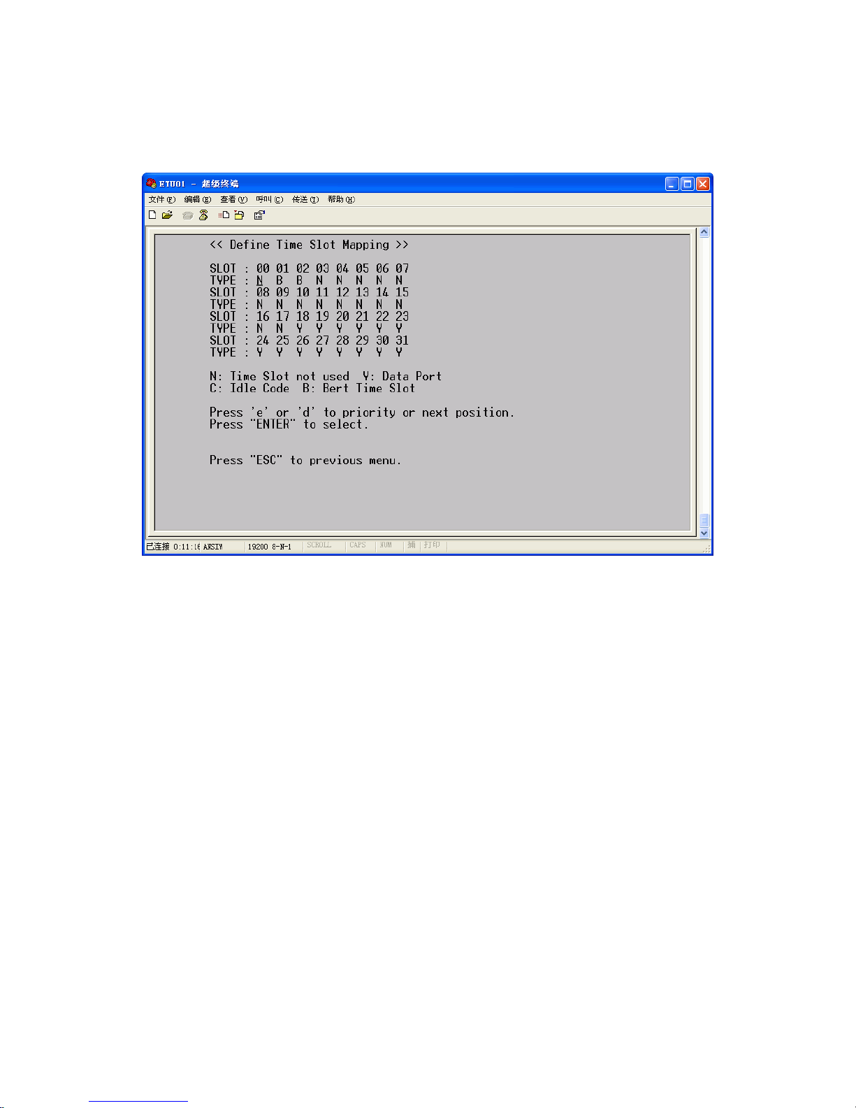
Press 6 to Define Time Slot Mapping
Pressing the space bar will move the cursor to the next timeslot entry. Repeatedly
pressing Enter will make the selection between 'Y, C, B and N'.
Note: While under FAS, TS0 & TS16 can not be assigned to B (BERT). While
under FAS+CAS, TS0 & TS16 can also not be enabled or assigned to B (BERT).
Enter ESC to return to the Define System Parameter menu.
Page 42
Chapter 4 Control Port Operation
42
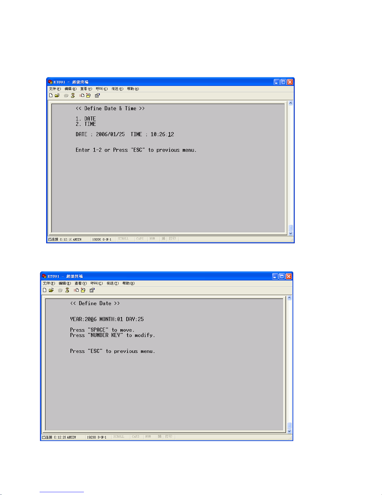
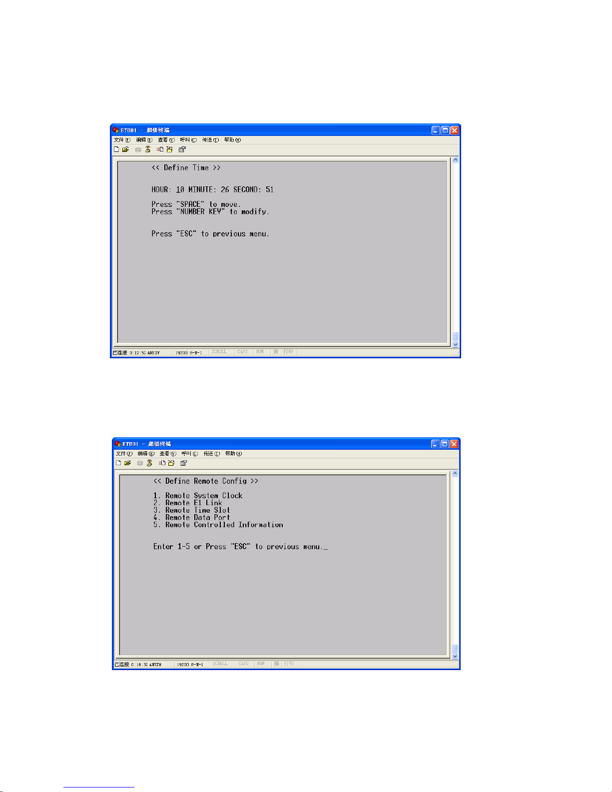
Press 7 to Define Time & Date
Pressing "1", the result is displayed as below
Page 43
Chapter 4 Control Port Operation
43
Pressing "2", the result is displayed as below
Enter ESC to return to the Define System Parameter menu.
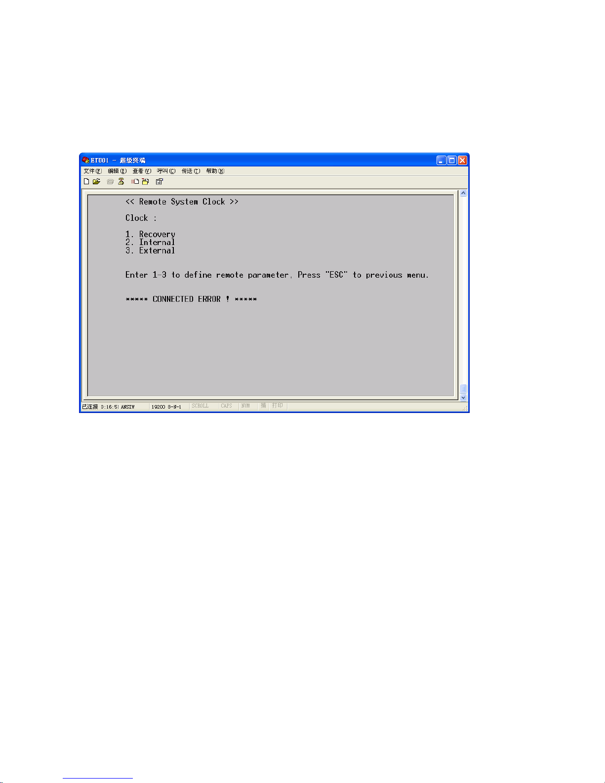
Press 8 to Define Remote Config
Notice: This function allows you to configure all the ETU01-D at the far-end side.
And the connected ETU01-D must under the normal CCS or CAS E1 mode
Page 44
Chapter 4 Control Port Operation
44
When press "1" at the menu here, you can configure the connected ETU01-Dsystem
clock at Remote side. The screen will display "CONNECTED ERROR" if the unit is
not under the normal E1 mode.
Page 45
Chapter 4 Control Port Operation
45
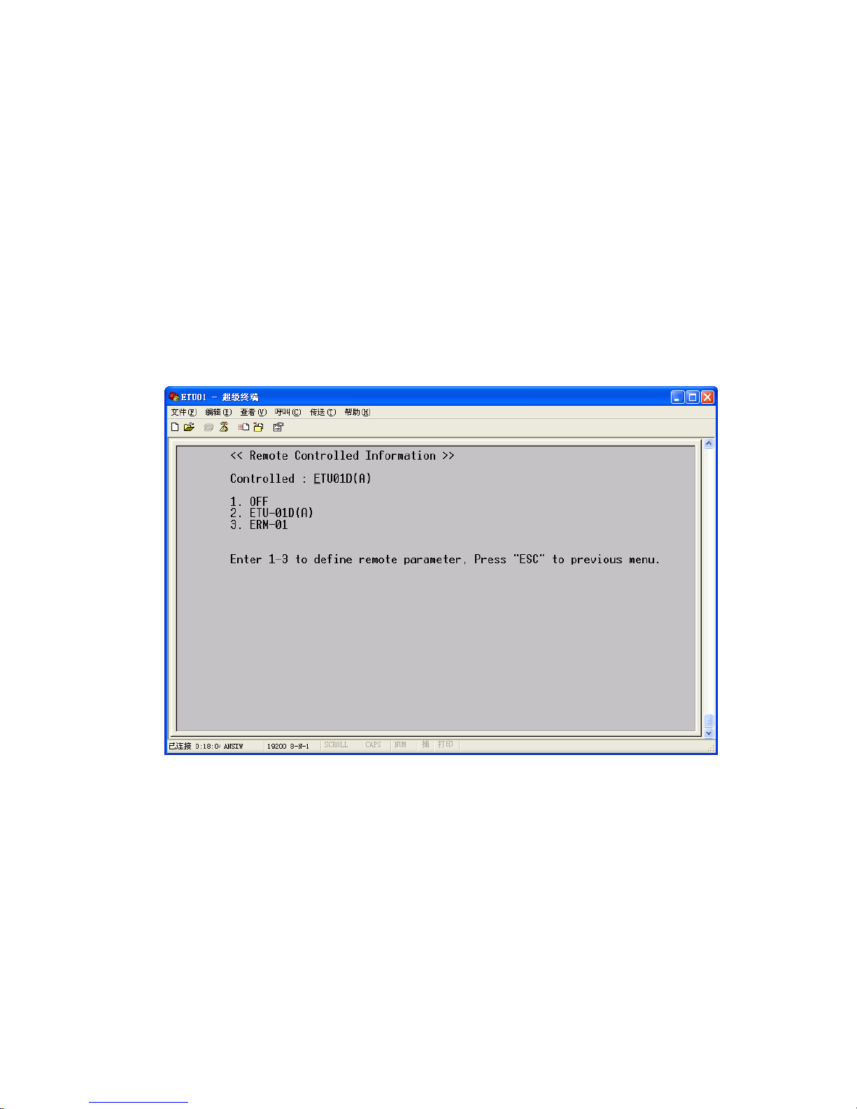
When pressing "5" at the menu here, the system will indicate the remote equipment
parameters. Here also can decide the local equipment can be configured from the
remote side equipment or not.
"OFF": The local ETU01-D can't be configured from the remote side.
"ETU01-D(A)": Configure the remote side equipment, under this option, the
equipment at the remote side is ETU01-D(A).
"ERM-01": Configure the remote side equipment, under this option, the equipment
at the remote side is E1 I/O card of ERM01.
Enter ESC to return to the Define System Status menu.
Page 46

Chapter 4 Control Port Operation
46
Now that all parameters have been set, it would be a good time to save all the
settings.
Enter 1 to Save & Reboot
Press Enter to confirm. The screen will display the message "Y/N: [N]". Press Enter
again, the screen will display the message “Y/N: [Y]” and then reboot system.
Press ESC again to go to the very top menu display.
Now press "3" to set up the Test Function Parameter. To do this, enter 3.
<< Define Test Mode Function >>
1. LoopBack Test
2. BERT Test
Enter 1-2 or press "ESC" to previous menu.
<< Save
& Reboot
>>
Press "ENTER" to confirm, "ESC" to previous menu.
Page 47

Chapter 4 Control Port Operation
47
To Define Loop Back Test Function, Press 1.
To enable or disable the Loop back function, Press 1.
The current setting for Loop Back is OFF. To turn on, press 1. To exit without
changing, press ESC.
<< Define LoopBack Test Function >>
Function : OFF
E1 : OFF Data Port
: OFF
1. Function
2. E1
3. Data Port
Enter 1-3 or Press "ESC" to previous menu.
<< LoopBack
Function >>
Function : OFF
1. ON
2. OFF
Enter 1-2 or press "ESC" to previous menu.
Page 48

Chapter 4 Control Port Operation
48
At "Define Loop back Test Function" , enter 2.
Press 2-6 to initiate a loop back of the E1 link, press 1 to stop loop back, or press
ESC to return to the previous menu without any change.
****IMPORTANT**** Remote loop backs are not possible when E1 is in
unframed mode.
Press 4 to Data Port loopback test function
Note: When Data Port Local Analog Loop Back is initiated, the DTE connected
should be providing its own Clock.
Enter ESC to return to the Define Test Mode Function menu.
<< E1 LoopBack >>
E1 : OFF
1. OFF
2. Local Analog
3. Local Digital
4. Local Payload
5. Remote Analog
6. Remote Payload
Enter 1-6 or Press "ESC" to previous menu.
<< Data Port1 LoopBack >>
Data Port : OFF
1. OFF
2. Local Analog
3. Local Digital
Enter 1-3 or Press "ESC" to previous menu.
Page 49

Chapter 4 Control Port Operation
49
Define BERT test function, press 2.
Press 1 to initiate or close the function; press 2 to define the BERT channel (refer to
Chapter 1); press 3 to define the BERT pattern; press ESC to exit without changing.
Press ESC one last time to reach to top level menu.
<< Define Test Mode Function >>
1. LoopBack Test
2. BERT Test
Enter 1-2 or press "ESC" to previous menu.
<< Define BERT Test Function >>
Function : OFF Channel : E1 Line
Pattern : 2E11-1
1. Function
2. Channel
3. Pattern
Enter 1-3 or Press "ESC" to previous menu.
Page 50

Chapter 4 Control Port Operation
50
There is no default password for ETU01-D
The following is an example of Password setting for the ETU01-D.
Press 4.
Enter 1 to set the Password
Here, the system only allows the user to enter the digital for the password, once you
enter the non-digital character and press "enter" key, the system will display "Your
Password Is Error"
Enter 123456. Then press ENTER, the screen will display: "Your Password is OK !"
<< Password >>
1. Set Password
2. Clear Password
Enter 1-2 or press "ESC" to previous menu.
<< Password >>
Enter Password (6 Number) :
Press "ENTER" to confirm, "ESC" to previous menu.
Press "SPACE" to clear.
Page 51
Chapter 4 Control Port Operation
51
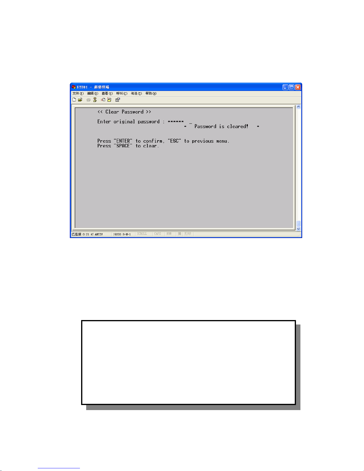
You may also clear the previous password by pressing "2" and the main menu for
setting password.
Enter the original password,. Then press ENTER, the screen will display:
Your Password is clear!
Press ESC.
Press ESC back to go back to the main menu.
To reset all parameters to the original factory default settings, press 5.
All settings are effected.
<< Reset Data to Fa
ctory Default >>
Reset Data is OK
Press "ENTER" to confirm, "ESC" to previous menu.
Page 52

Chapter 4 Control Port Operation
52
Press ESC.
To exit the terminal mode, press 6. The terminal connection will be dropped and the
front panel LCD will return to its normal 'RUN' condition.
****IMPORTANT****
The unit will not transmit normally unless it is in RUN mode.
This completes the detailed examples of terminal mode operation for the ETU01-D.
Page 53
Chapter 4 Control Port Operation
53
The command list for the Hyper Terminal
Main Menu Secondary Level
Menu
Third-Level
Menu
Fourth Level
Menu
Options
ENTER/EXIT
System Clock
E1 Line
Data Port
Time Slot
Display Alarm
Buffer
Display Remote
Alarm Buffer
Alarm Buffer
Clear Alarm
Buffer
LoopBack Test
BERT Test
Display System
Status
Performance
Save & Reboot
Reboot System
Internal
External
System Clock
Recovery
HDB3 Link Code
AMI
75ohm Impedance
120ohm
Short LBO
Long
ON TX Jitter
OFF
ON RX Jitter
OFF
Unframe
CCS
Frame
CAS
ON CRC-4
OFF
Define System
Parameter
E1 Parameter
Idle Code 00~FF
Page 54
Chapter 4 Control Port Operation
54
DCE Clock
DTE
TX Pos RX Pos
Data Port
Parameter
Clock Polarity
TX Pos RX Neg
TX Neg RX Pos
TX Neg RX Neg
Time Slot
Mapping
Date & Time
Internal
External
Remote System Clock
Recovery
Remote Frame
Remote CRC-4
Remote Cascade
Remote Idle
Code
Remote RAI
Remote Line
Code
Remote
Impedance
Remote E-BIT
Remote LBO
Remote TX Jitter
Remote E1 Link
Remote RX Jitter
Remote Config
Remote Time Slot
Page 55

Chapter 4 Control Port Operation
55
N64 Multiplier
N56
ON CTS
RTS
ON V.54 Loop
Status
OFF
Port Type
DCE
Remote Data
Port
Clock
DTE
TX Pos , RX Pos
TX Pos , RX Neg
TX Neg , RX Pos
Clock Polarity
TX Neg , RX
Neg
ON Function
OFF
Close
Local Analog
Local Digital
Local Payload
Remote Analog
E1
Remote Payload
Close
Local Analog
LoopBack Test
Data Port
Local Digital
ON Function
OFF
Channel E1 Line
2E11-1
2E15-1
Test
Function
Parameter
BERT Test
Pattern
QRSS
Set Password Password
Clear Password
Reset Data
to Default
EXIT
Page 56

Chapter 4 Control Port Operation
56
This page left blank intentionally.
Page 57
Chapter 5 Loopback and BERT Tests
57
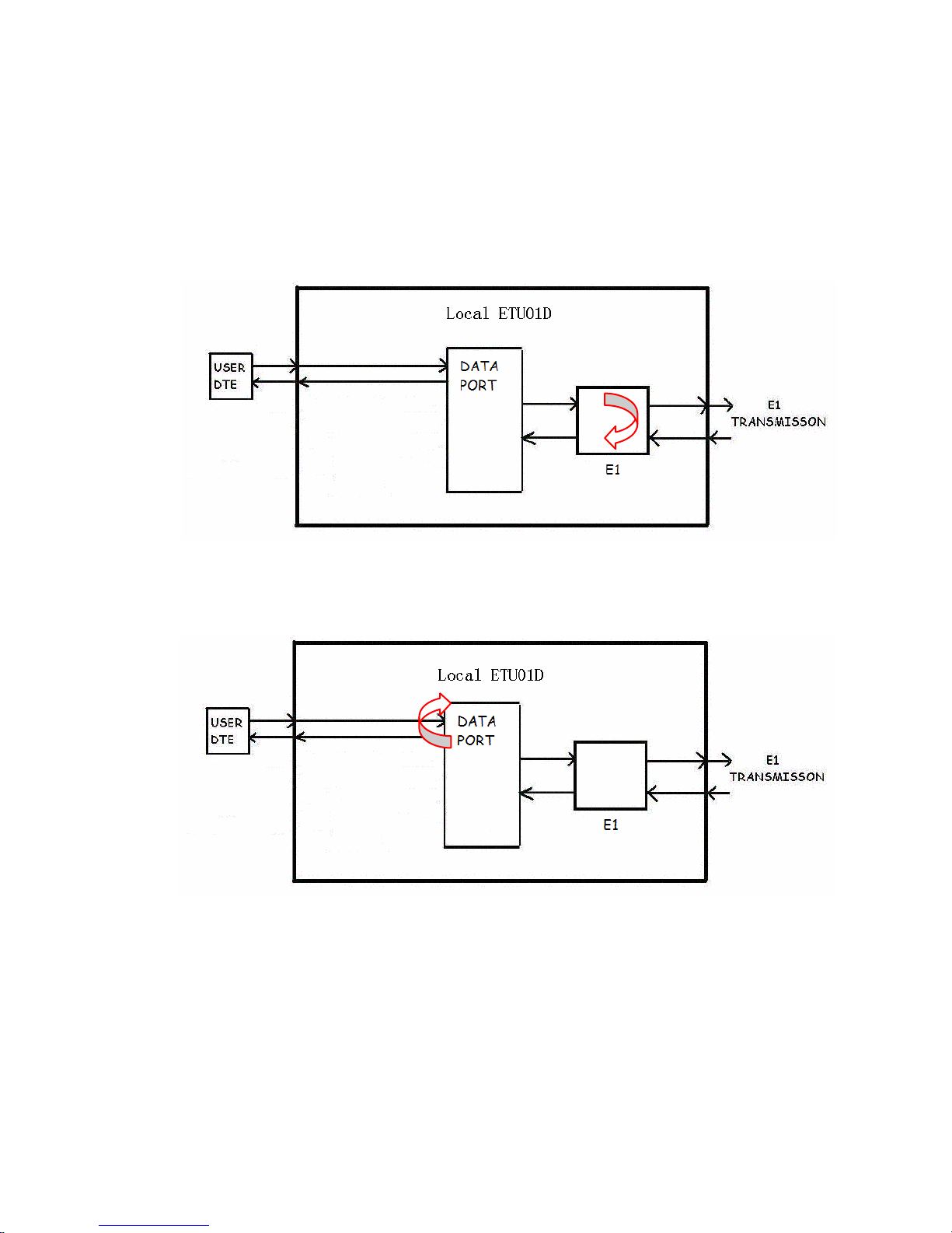
5.1 Test Loops
–E1 link loop back
- local analog loop back
-
- local digital loop back
-
Page 58
Chapter 5 Loopback and BERT Tests
58
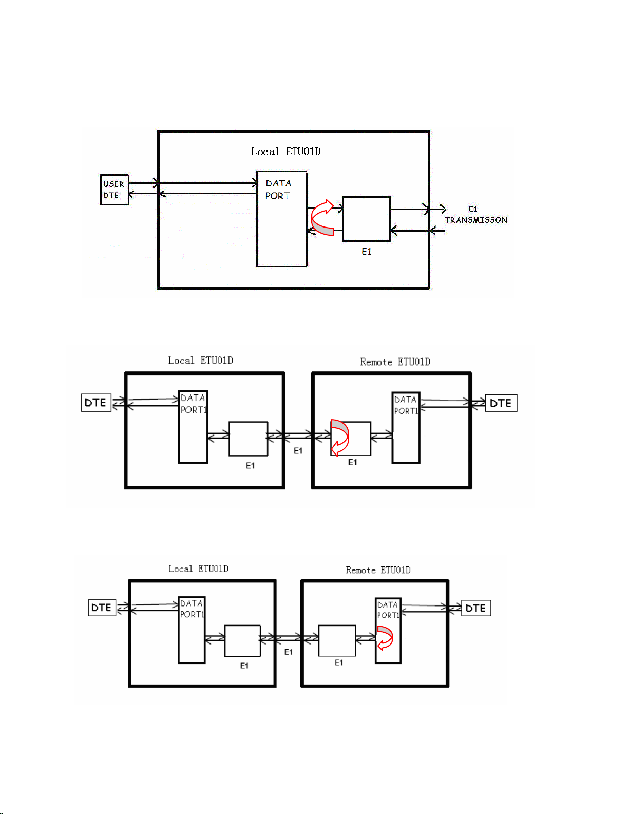
- local payload loop back
- remote analog loop back
- remote payload loop back
Page 59
Chapter 5 Loopback and BERT Tests
59
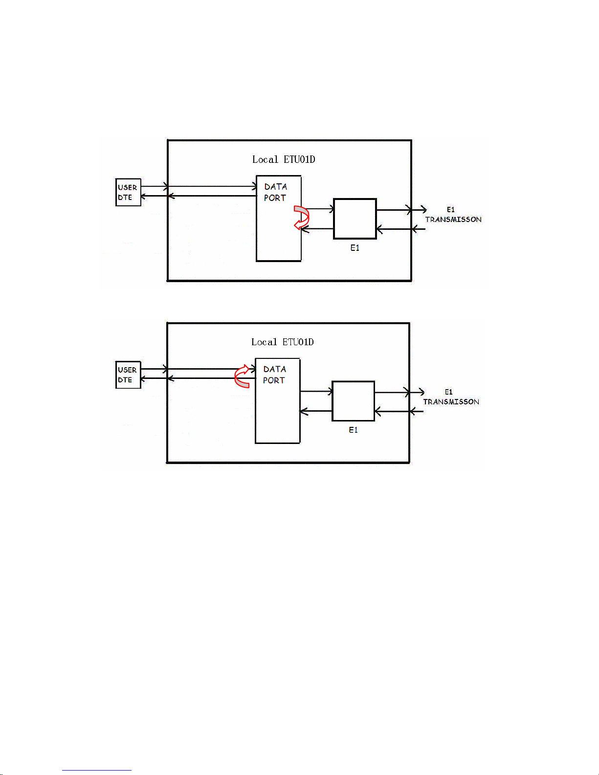
–Data Port loop back
-Data Port1 local analog loop back
- Data Port1 local digital loop back
Notice: The Remote loop back tests are only available under the E1 framed mode,
either in CCS or CAS.
Page 60
Chapter 5 Loopback and BERT Tests
60
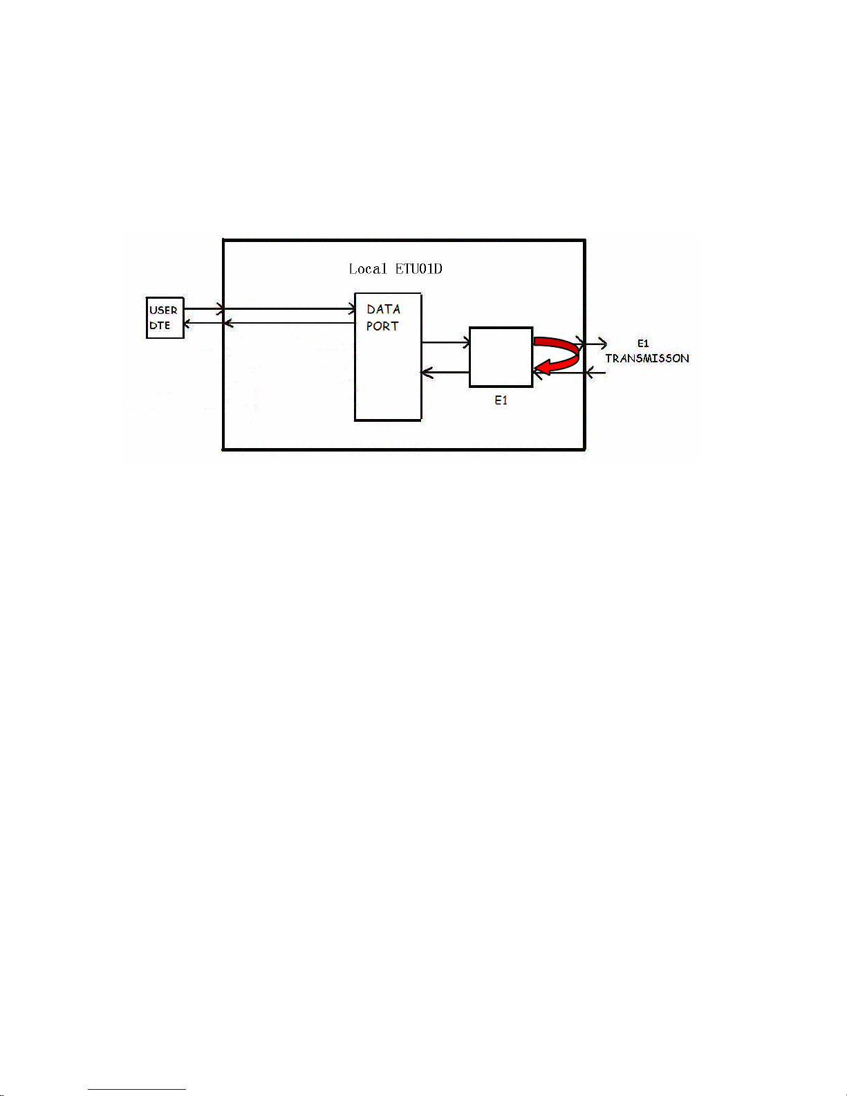
BERT TEST:
-E1
Page 61
Appendix A
61
Appendix A
A.1
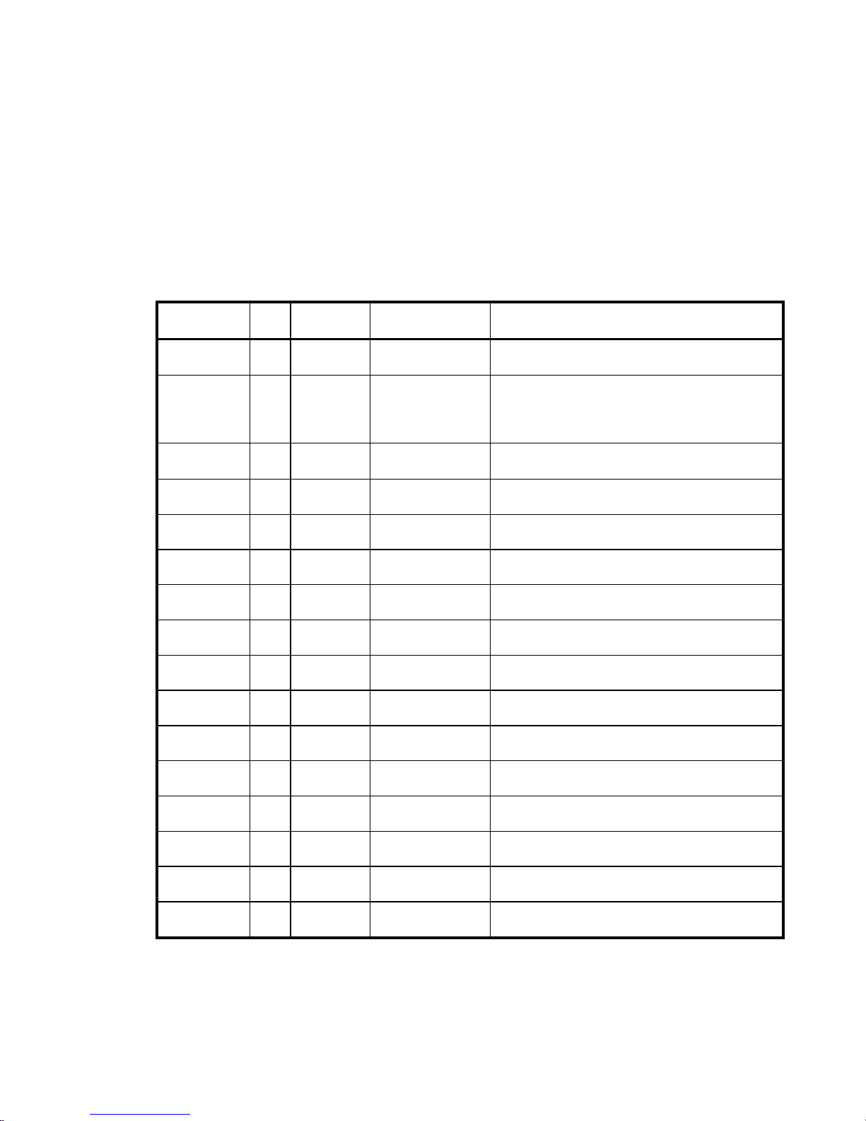
ETU01-D comes with a V.35 interface, the physical
interface is a 34-pin female M-Block type connector wired in
accordance with Table as below.
SIGNAL
FUNCTION
PIN CIRCUIT DIRECTION DESCRIPTION
Protective
Ground
A Frame ↔↔↔↔
Chassis ground.
May be isolated from signal ground.
Signal
Ground
B
Signal
Ground
↔↔↔↔ Common signal ground.
Transmitted
Data
P
S
TD(A)
TD(B)
To ETU-01D Serial digital data from DTE.
Received
Data
R
T
RD(A)
RD(B)
From ETU-01D
Serial digital data at the output of the ETU-01D
receiver.
Request to
Sent
C
RTS
To ETU-01D
An ON signal to the ETU-01D when data
transmission is desired.
Clear to
Sent
D
CTS
From ETU-01D Constantly ON.
Data Set
Ready
E
DSR
From ETU-01D
Constantly ON,
except during test loops.
Data Terminal
Ready
H
DTR
To ETU-01D Not used.
Data Carrier
Detect
F DCD From ETU-01D
Constantly ON, except when a loss of the received
carrier signal is detected.
External
Transmit clock
U
W
ETC(A)
ETC(B)
To ETU-01D
A transmitted data rate clock input from the data
source.
Transmit
Clock
Y
AA
TC(A)
TC(B)
From ETU-01D
A transmitted data rate clock for use by an
external data source.
Receive
Clock
V
X
RC(A)
RC(B)
From ETU-01D
A received data rate clock for use by an external
data source.
External
Receive clock Z BB
ERC(A)
ERC(B)
To ETU-01D
A received serial data rate clock input from the
DTE.
Remote
Loop back
HH RL To ETU-01D
When on, commands ETU-01D into remote loop
back, can disable by DIP sw.
Local
Loop back
JJ LL To ETU-01D
When on, commands ETU-01D into local loop
back, can disable by DIP sw.
Test Indicator KK TM From ETU-01D ON during any test mode
Table A-1 V.35 user data channel connector pin allocation
Page 62

Appendix A
62
Page 63

TECHNICAL INQUIRY FORM
CTC Union Technologies Inc
Attn : Technical Support Division
From Company:
Name:
Tel: ( )
Fax:( )
MODEL: ETU01-D
ACTIVITY: Check every setting including physical interface and
system setting
SYS CONFIGURATION:
Question:
Fax:+886
-2-
2799
-
1355
Tel:+886-2-2659-1021
E-mail:[email protected]
Taipei Taiwan
Page 64
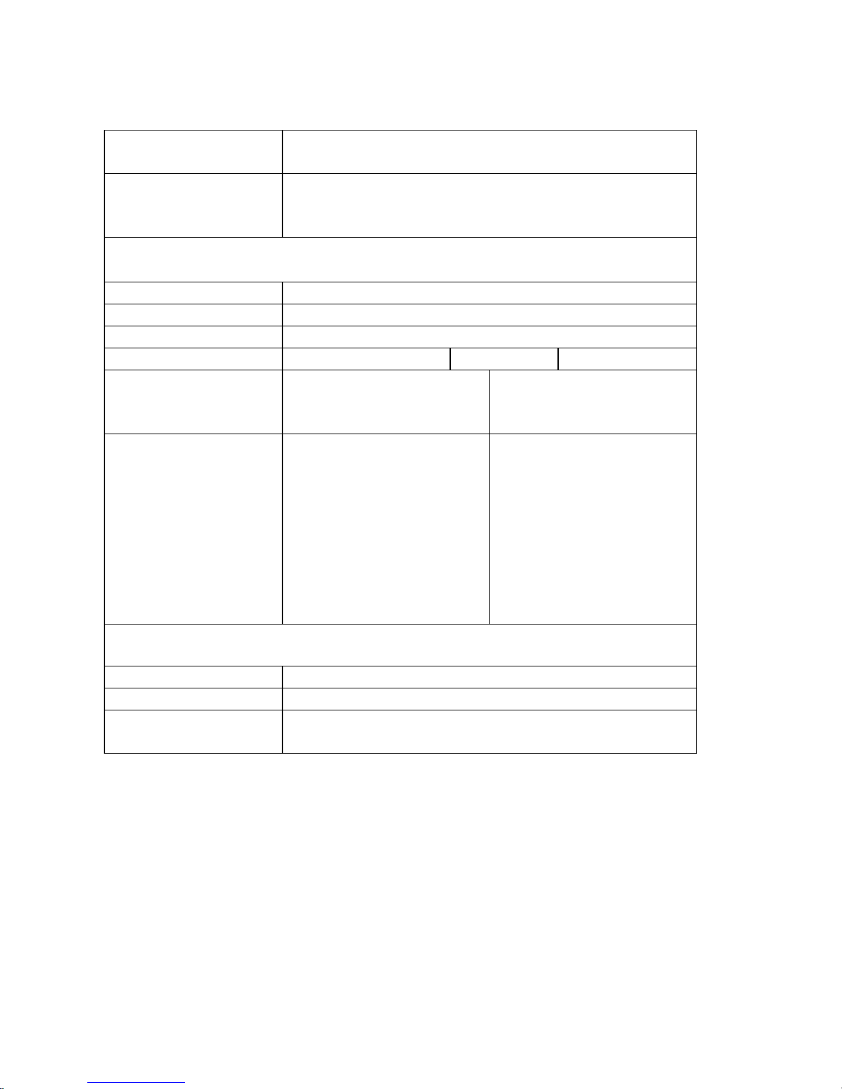
Parameters User setting; check all configurations
Applications Point-to-point
ETU01-D to E1 Network device
System Clock INTERNAL
RECOVERY (E1)
EXTERNAL
Main E1 link parameters
Line Code AMI / HDB3
Line Impedance Unbalanced 75 ohms / Balanced 120 ohms
LBO Long / Short
Tx Jitter ON / OFF Rx Jitter ON / OFF
Frame Unframed
-FAS (PCM31)
-FAS+CAS (PCM30)
-CRC4 ON / OFF
-IDLE CODE (00-FF)
Time slot mapping
N: Not assigned
Y: Data Channel .
C: Insert idle code on E1
Tx side.
(Refer to E1 Link
Parameter Detail to set the
idle code.)
B: BERT test.
Data port parameter
Data port V.35
Clock select DCE / DTE
Clock polarity TX POS RX NEG / TX POS RX POS
TX NEG RX POS / TX NEG RX NEG
Page 65

Page 66

E1 Series
CTC Union Technologies Co., Ltd.
Far Eastern Vienna Technologies Center
(Neihu Technology Park)
8F, No. 60, Zhouzi St., Neihu, Taipei, Taiwan
Phone:+886-2-2659-1021 Fax:+886-2-2799-1355
E-mail: [email protected] http://www.ctcu.com
 Loading...