

Page 1
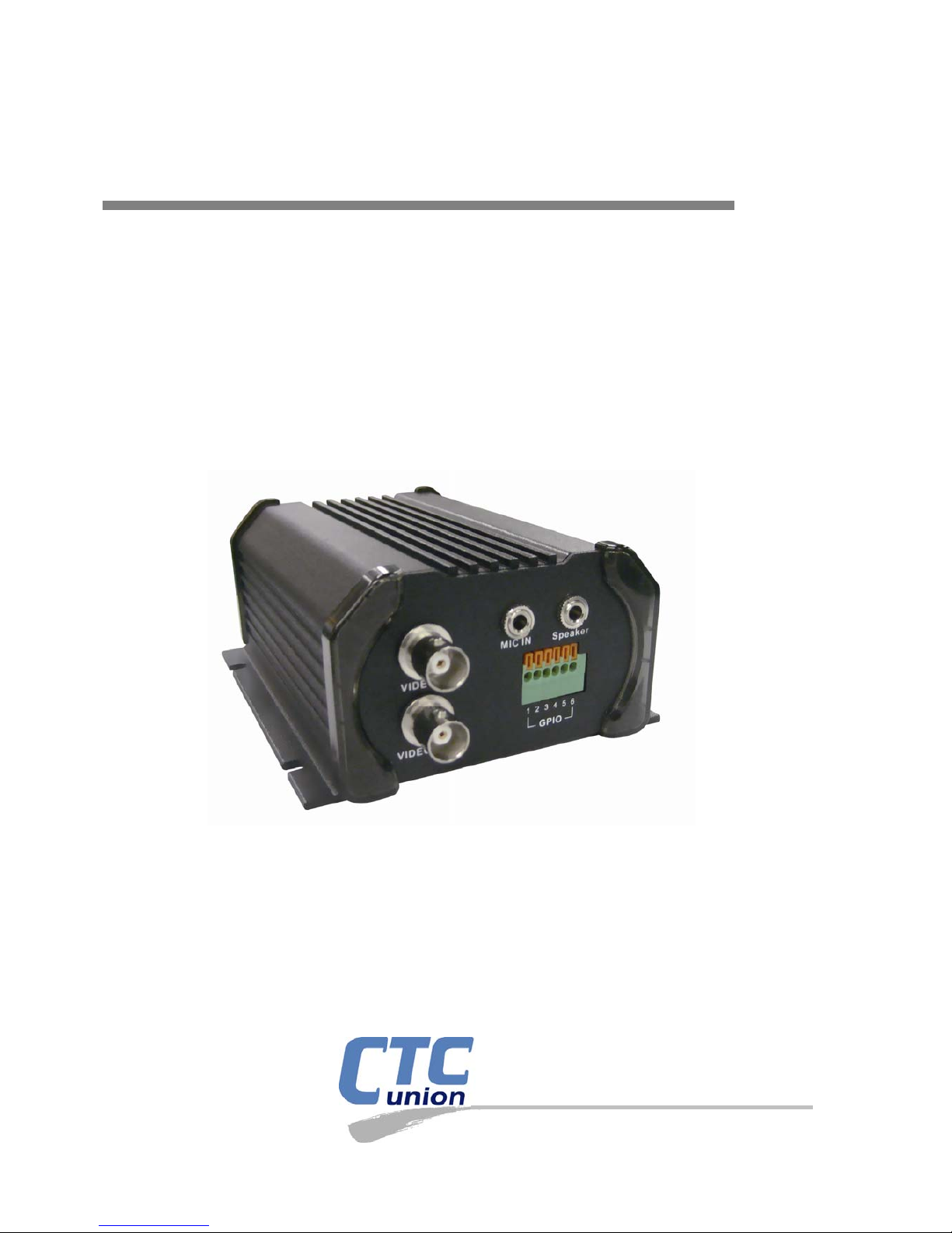
USER MANUAL
DVS-8301
Digital Video Server, 1 ch. Dual Stream
CTC Uni
on Technologies Co.,
Ltd
.
Page 2

Page 3

LEGAL
The information in this publication has been carefully checked and is believed to be entirely
accurate at the time of publication. CTC Union Technologies assumes no responsibility , however,
for possible errors or omissions, or for any consequences resulting from the use of the
information contained herein. CTC Union Technologies reserves the right to make changes in its
products or product specifications with the intent to improve function or design at any time and
without notice and is not required to update this documentation to reflect such changes.
CTC Union Technologies makes no warranty, representation, or guarantee regarding the
suitability of its products for any particular purpose, nor does CTC Union assume any liability
arising out of the application or use of any product and specifically disclaims any and all liability,
including without limitation any consequential or incidental damages.
CTC Union products are not designed, intended, or authorized for use in systems or applications
intended to support or sustain life, or for any other application in which the failure of the product
could create a situation where personal injury or death may occur. Should the Buyer purchase or
use a CTC Union product for any such unintended or unauthorized application, the Buyer shall
indemnify and hold CTC Union Technologies and its officers, employees, subsidiaries, affiliates,
and distributors harmless against all claims, costs, damages, expenses, and reasonable attorney
fees arising out of, either directly or indirectly, any claim of personal injury or death that may be
associated with such unintended or unauthorized use, even if such claim alleges that CTC Union
Technologies was negligent regarding the design or manufacture of said product.
TRADEMARKS
Microsoft is a registered trademark of Microsoft Corp.
HyperTerminal™ is a registered trademark of Hilgraeve Inc.
User Manual
Version 1.0 Oct 2007 First Release
This manual supports the following:
DVS-8301
This document is the first official release manual. Please check CTC Union's website for any
updated manual or contact us by E-mail at [email protected]. Please address any comments for
improving this manual or to point out omissions or errors to [email protected]. Thank you.
CTC Union maintains a support web site (support.ctcu.com) where you may obtain the latest
manual, quick installation guide, and operational firmware. Membership to this web site is free,
however, you must be a registered member in order to access any software updates.
CTC Union Technologies Co., Ltd.
2008 Copyright, All rights reserved.
Page 4

BEFORE USING THIS PRODUCT
This CTC Union product has been designed with safety in mind. However, if not used properly,
electrical products can cause fires which may lead to serious bodily injury. To avoid such
accidents, be sure to heed the following.
Legal Caution:
Video and audio surveillance may be forbidden by laws that vary from country to country. Please
check the laws in your local region before using this product for surveillance purposes.
Heed the safety precautions
Be sure to follow the general safety precautions and the “Operation Notice.”
In case of a breakdown
In case of system breakdown, discontinue use and contact your authorized CTC Union dealer.
In case of abnormal operation
• If the unit emits smoke or an unusual smell,
• If water or other foreign objects enter the cabinet, or
• If you drop the unit or damage the cabinet:
1 Disconnect the cable and the connecting cables.
2 Contact your authorized CTC Union dealer or the store where you purchased the product.
Operation Notice - Operating or storage location
Avoid operating or storing this unit in the following locations:
• Extremely hot or cold places (Operating temperature: 0 °C to +50 °C [32 °F to 122°F])
• Exposed to direct sunlight for a long time, or close to heating equipment (e.g., near heaters)
• Close to sources of strong magnetism
• Close to sources of powerful electromagnetic radiation, such as radios or TV transmitters
• Locations subject to strong vibration or shock
Ventilation
To prevent heat buildup, do not block air circulation around the device.
Transportation
When transporting the unit, repack it in its original packaging or in materials of equal quality.
Cleaning
• Use a soft, dry cloth to clean the external surfaces of the device. Stubborn stains can be
removed using a soft cloth dampened with a small quantity of detergent solution, then wipe dry.
• Do not use volatile solvents such as alcohol, benzene or thinners as they may damage the
surface.
Page 5

CHAPTER#1 INSTALLATION 1
CHAPTER#2 USING IP CAMERA VIA MOBILE PHONE 2
CHAPTER#3 USING IP CAMERA VIA WEB BROWSER 3
CHAPTER#4 HOW TO USE 4
4.1.
INITIAL ACCESSING THE VIDEO SERVER 5
4.2. CONFIGURATION OF MAIN MENU 6
4.2.1 Setting 6
4.2.2 Client Setting 7
4.2.3 Image Setup 7
4.2.4 PTZ Control 7
4.2.5 Live View 8
4.3.
BASIC SETTING 9
4.3.1 System 9
4.3.2 Camera 12
4.3.3 Network 17
4.3.4 Security 23
4.4. ADVANCE SETTING 25
4.4.1 PTZ Control 25
4.4.2 Preset Postion 26
4.4.3 Patrol 27
4.4.4 FTP Client 28
4.4.5 SMTP 32
4.4.6 HTTP Event 37
4.4.7 Alarm Output 39
4.4.8 Schedule 41
4.4.9 Alarm Input 42
4.4.10 Alarm Buffer 43
4.4.11 Motion Detection 44
4.4.12 System Log 45
Page 6

Page 7
CHAPTER 1 Installation
1
CHAPTER 1 Installation
Installation Steps
Follow these steps to install the CTC Union DVS-8301 on your LAN:
1. Check the package contents against the list below.
2. Setup the device. See IP Installer User Manual on the available methods.
Package Contents
Video Server CTC Union DVS-8301 1 channel Video Server
Power Adapter Country-specific
CD User manual/IP Installer and Documents
Printed Document Quick installation guide
Overview
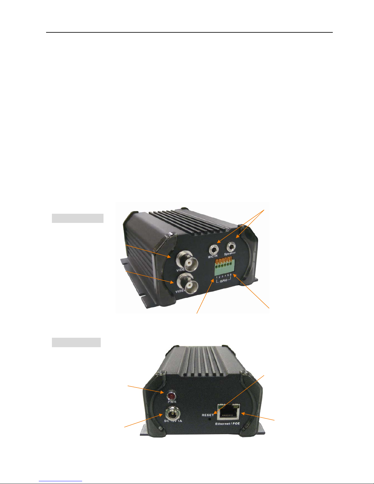
Front Panel:
Rear Panel:
Video In
Video out
5~6-Pin : RS485
Pin1: DI+ Pin2:DI-
Pin3: COM. Pin4:N.O.
Mic In & Line Out
LED indicators for
power
Reset
Network / POE
connector
Power adapter
connector
Page 8

CHAPTER 2 Using IP Camera via Mobile Phone
2
CHAPTER 2 Using IP Camera via Mobile Phone
To use IP cameras via mobile phones, please make sure your RTSP is set to “ON”.
(Default is “ON”) To change the settings of IP cameras, please see “Settings” for details.
3G Mobile Phone viewing
For 3G mobile phone viewing, type “rtsp://<IP>:<PORT>/video.3gp” into your 3G web
browser. <IP> is the IP address of your IP camera, <PORT> is the RTSP port of your IP camera
(Default value is 8554.)
Example: rtsp://100.10.10.1:8554/video.3gp
Note:
• You can also use RTSP clients (RealPlayer, MPlayer, Windows Media Player,
Quicktime…etc.) to view RTSP streaming, just type in “rtsp://<IP>:<PORT>/video.3gp” as
the Player’s URL
2.5G Mobile Phone viewing
For 2.5G mobile phone viewing, type “<IP>/mobile.wml” into your 2.5G web browser. <IP> is
the IP address of your IP camera.
Page 9
CHAPTER 3 Using IP Camera via Web Browser
3
CHAPTER 3 Using IP Camera via Web Browser
System Requirement
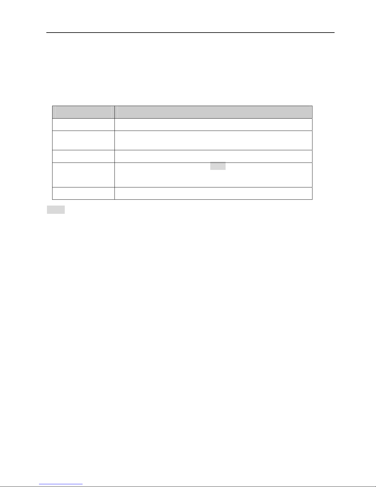
To use the product normally, we strongly recommend your computer follows our minimum
system requirement (Computer level lower than this might cause some problems)
Item Requirements
CPU Pentium 4 1600MHz (or equivalent AMD)
Graphic Card 64MB RAM graphic cards (or equivalent on-board graphic
cards)
RAM 512MB
Operating System Windows 98, ME (Please see Note)
Windows 2000, 2003, XP, Vista
Web Browser Internet Explorer 6 or later
Note:
• If you’re using Windows 98 or ME, please install IP Installer before using WEB UI to ensure
the system runs normally.
Page 10

CHAPTER 4 How to Use
4
CHAPTER 4 Configuration
This chapter introduces how to monitor the image from the device using Microsoft Internet
Explorer web browser. The CTC Union Digital Video Server (DVS) can be used with Microsoft
web browsers and Intelligent IP Installer in Windows operation systems. The recommended
browser for Windows is Internet Explorer 6.0 or above. If you want to know how to use CTC
Union DVS with Intelligent IP Installer, please check the Intelligent IP Installer User’s Manual
for Windows operation systems.
The functions of the device should be set by the Administrator. For further instructions on
setting the device, see “Setting” section.
Note:
Microsoft's Internet Explorer must be used and the Active-X plug-in embedded in the DVS
must be allowed to install in the web browser. The Active-X plug-in is required in order to view
video within Internet Explorer. Currently, only Microsoft's browser supports Active-X. Use of
other browsers such as Mozilla Firefox or Opera will allow contion but no video will be able to
be displayed. If you see no video displayed in you Internet Explorer browser, make sure that
the Active-X plug-in was properly installed.
Page 11
5
4.1. Initially accessing the Video Server
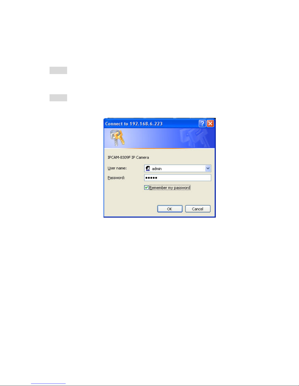
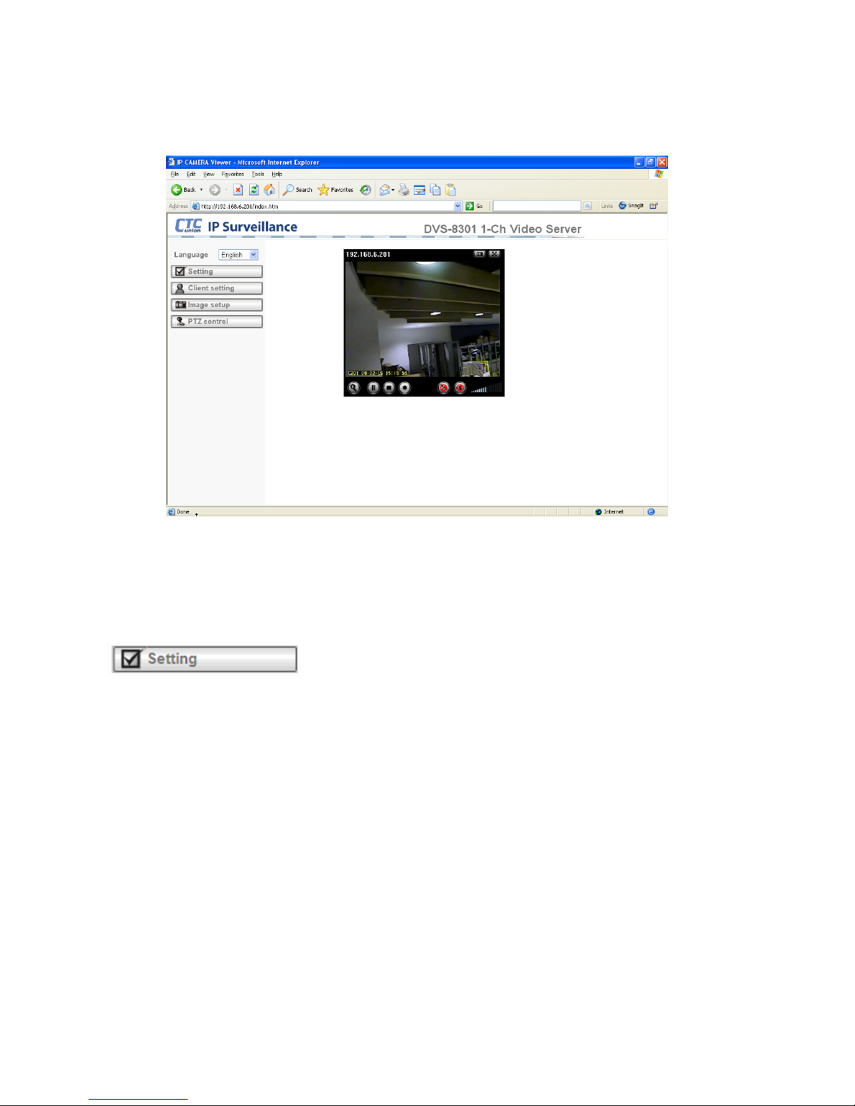
1. Start your web browser, and enter the IP address or host name of the CTC Union IP camera in
the Location / Address field of your browser.
Note:
• If you only want to view the video without seeing the setting page, enter
“http://<IP>/index2.htm” as your web URL.
2. Use the default account “admin” and default password “admin”.
Note:
• The default user name “admin” and the password are set at the factory for the
administrator. You can change them in the Account Menu under Setting on page 19.
3. The monitor image will be displayed in your browser.
Page 12
6
4.2. Configuration of Main Screen
Language
You can click the pull-down box to select the system language, including English,
Traditional Chinese, Simplified Chinese, German, Japanese or Spanish.
4.2.1 Setting
This function is only for the Administrator. Click this button to get into the Basic and Advance
settings screen.
Page 13
7
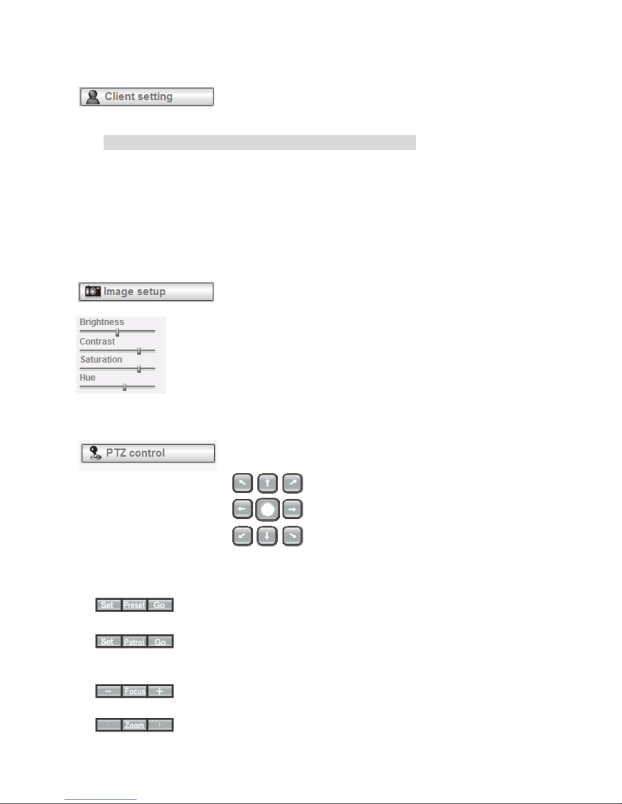
4.2.2 Client Setting
Mode: Click the pull-down box to choose between MPEG-4 and M-JPEG (Motion JPEG) video
compression modes.
Note:MJPEG streaming is unavailable if RTSP mode is ON.
View Size: Select the desired display image resolution to 640X480 (4CIF) or 320X240 (CIF).
Protocol: Select the transferring protocol from TCP, UDP, HTTP and Multicast.
Video Buffer: Turn the Video Buffer function On/Off. The Video Buffer function makes the
streaming more smooth in slow or heavy traffic network environment. Buffering might
cause a slight delay in live viewing.
4.2.3 Image Setup
You can use the tool bar to optimize video brightness, contrast, and
saturation.
4.2.4 PTZ Control
Pan / Tilt control buttons:
Click the arrow button of the direction you want to instruct the Video Server to move the
speed dome camera.
Other camera control functions:
Move the camera to a pre-defined position.
Before you start this function, you need to specify Guard tour settings in the Setting
Menu under Advance / Patrol setting.
Adjust camera focus.
Adjust camera optical zoom.
Page 14
8
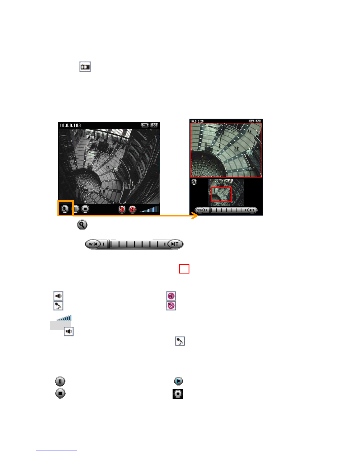
4.2.5 Live View
Snapshot:
You can capture a still image shot from the camera and save it in your computer.
1. Press , and a snapshot window will appear.
2. Click “Save” to save the picture in your computer.
3. Click “Close” to return to the view page.
Zoom in / out the image via the monitor window
1. Click to display the digital zoom in window.
2. Pull the to adjust the digital zoom range,
and it will be shown on the above window.
3. You can left click your mouse to move the to any location on the window.
Audio buttons:
:Speakers turned on. :Speakers turned off.
:Microphone turned on. :Microphone turned off.
: Volume control bar.
Note:
• It means the speakers of your computer are turned on to transmit the sounds from
the connected IP camera(s). Similarly, means you can broadcast to the connected
IP camera(s) via the Ethernet using your microphone.
Video play buttons:
:Pause the current video :Play the video.
:Stop the current video. :Record the current video.
Page 15
9
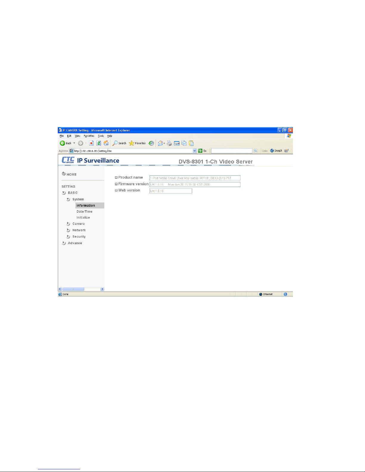
4.3. Basic SETTING
Click the “Basic” menu item to display the sub menus, including System, Camera,
Network, and Security.
4.3.1 System
4.3.1.1 Information
This information page provides you with product information, including Product name,
Firmware version, and Web version.
Page 16
10
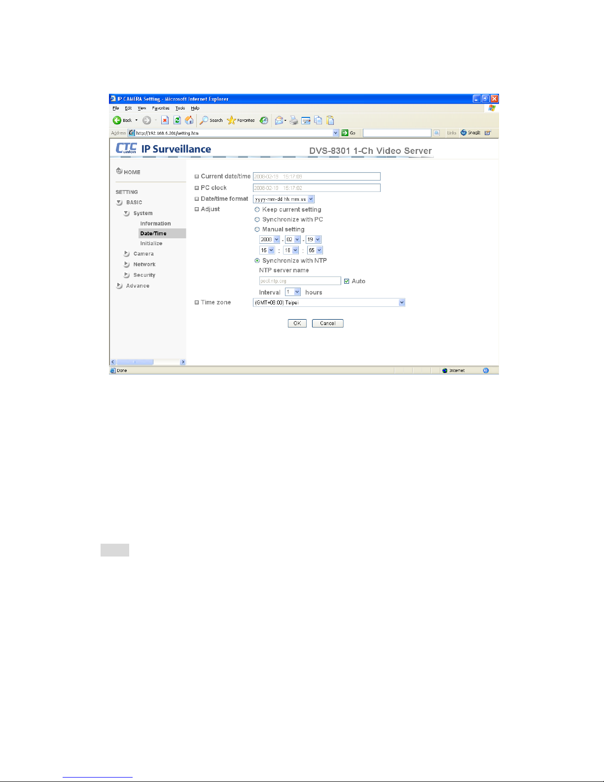
4.3.1.2 Date & Time Setting
Current date & time:This displays the current date and time of the device.
PC clock:This displays the date and time of the monitoring PC clock.
Date & time format:Click the pull-down box to select among different time display formats,
including yyyy-mm-dd hh:mm:ss (year-month-day hour:minute:second), mm-dd-yyyy
hh:mm:ss (month-day-year hour:minute:second), and dd-mm-yyyy hh:mm:ss
(day-month-year hour:minute:second).
Adjust:Select one of four time adjusting modes.
Keep current setting:Select this mode to keep the current date and time of the device.
Synchronize with PC:Select this mode to make the date and time of the device the same as
the monitoring PC.
Manual setting:Select this mode to manually adjust the date & time of the device.
Synchronize with NTP:Specify the NTP server name and the Refresh Interval to
synchronize the date and time of the device with those of the time server, known as the NTP
(Network Time Protocol) server.
Note:
• The NTP server (Network Time Protocol) is the time server which is an Internet
standard protocol (built on top of TCP/IP) that assures accurate synchronization to the
millisecond of computer clock times in a network of computers.
NTP server name:Type the host name or IP address of the NTP server, up to 64 characters.
Time zone:Select the time zone and time difference from Greenwich Mean Time in the area
where the device is installed from the pull-down box.
Page 17
11
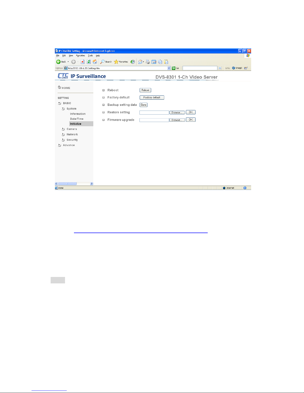
4.3.1.3 Initialization
Reboot:Click this button to reboot the device. A confirmation dialogue will appear. Click OK
to proceed. It takes about two minutes to reboot the device.
Factory default:Click this button to reset the device to the factory default settings. A
confirmation dialogue will appear. Click OK to proceed, the network indicator on the device
will start to blink. After completing adjustments to the default settings, the device will reboot
automatically. Do not turn off the device until the device reboots.
Backup setting data:Save the setting data of the device to a file. Click Save, and follow the
instructions on the browser to save the setting data file to your specified location.
Restore setting:Load the saved setting data of the device. Click Browse and select the file in
which the setting data is stored. Click OK, and the device is adjusted according to the loaded
data and restarted.
Firmware update:Upgrade the device software. Click Browse and select the file for
upgrading. A confirmation dialogue will appear. Click OK to start upgrading. The device will
reboot upon completion.
Note:
• Use only upgrade files that are specific for this device. Problems may occur otherwise.
• Do not turn off the device power or disconnect the network until the upgrading is
completed.
Page 18
12
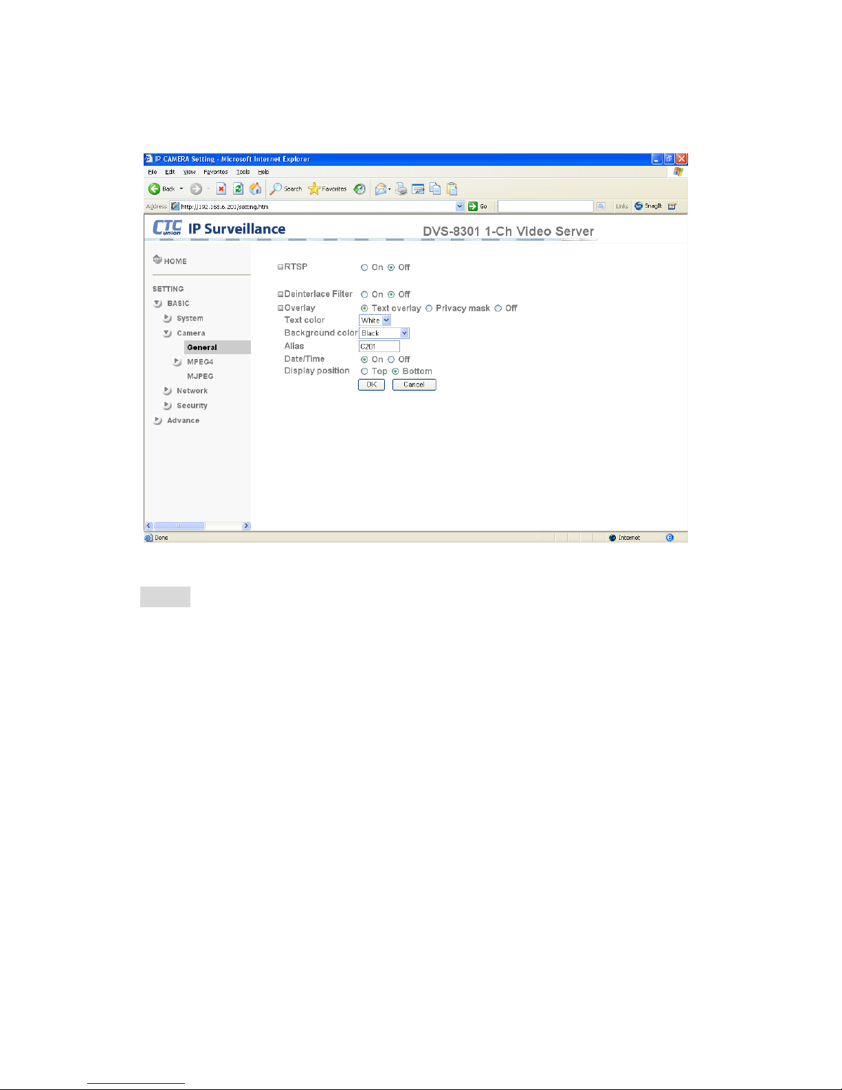
4.3.2 Camera
4.3.2.1 General
RTSP: Switch the RTSP streaming On/Off.
Note:
• RTSP: Real Time Streaming Protocol. RTSP is supported by most media clients.
(RealPlayer, Media Player, QuickTime, etc…)
Deinterlace Filter:Switch the deinterlace filter on/off.
Overlay:Select to add Text Overlay or Privacy Mask on/off the display screen.
Text Overlay:Enables users to see some information on the display screen, including
Date/Time and user-defined text. You can also change the background color.
Privacy Mask:Enables users to conceal an area of the video image.
Page 19
13
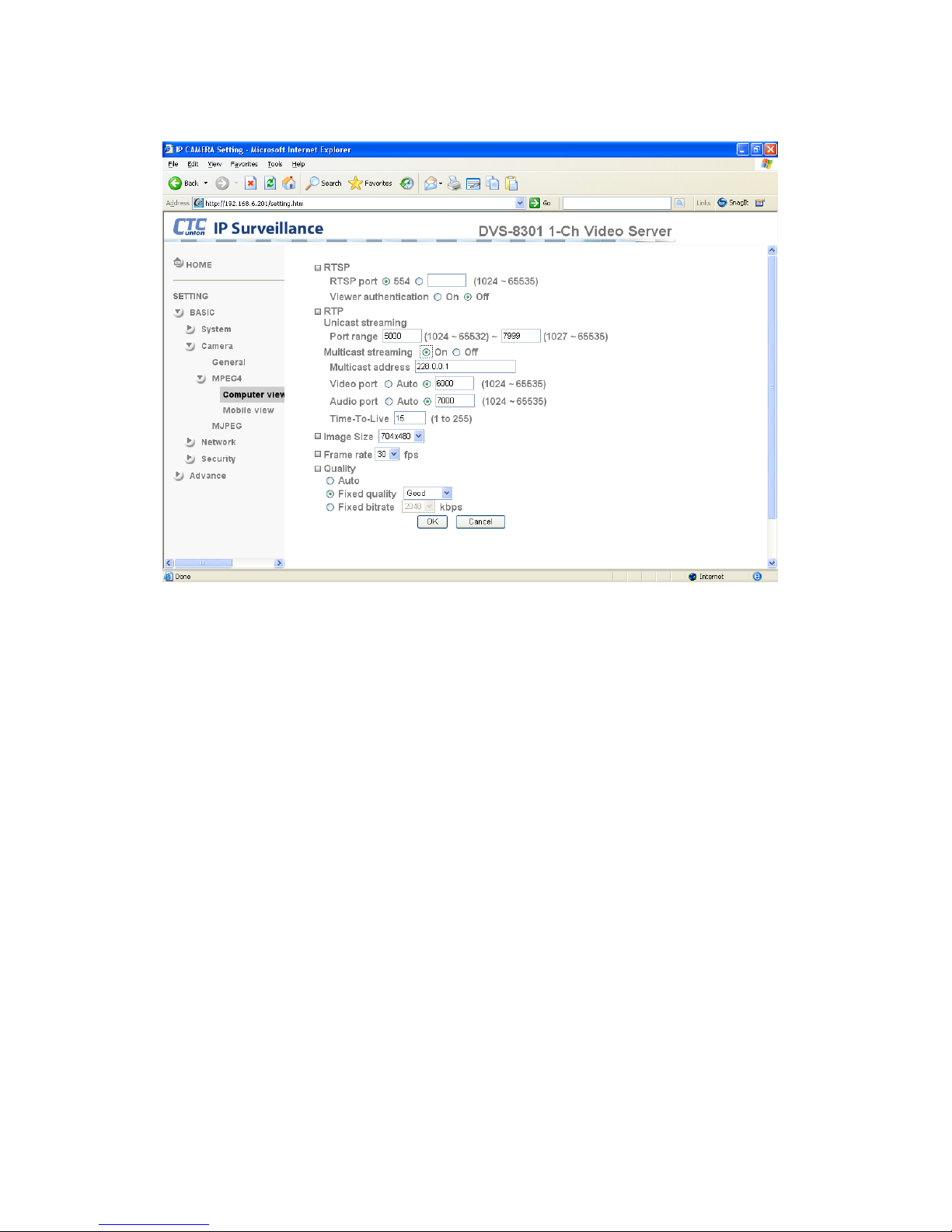
4.3.2.2 MPEG-4
Computer View
RTSP (If RTSP mode is ON)
RTSP port: Specify the transmission port number for RTSP streaming video. Default
value is 554.
Viewer authentication: If the viewer authentication is ON, users viewing through RTSP
will be requested to key-in username and password.
RTP (If RTSP mode is ON)
Unicast streaming:
Unicast streaming Video/Audio port range: Specify the transmission port range for
RTP streaming video. RTP will select a port randomly from the range.
Multicast streaming:
Multicast address: Specify the multicast server address.
Video / Audio Port: Specify the transmission port number of the video data. Specify an
even number from 1024 to 65534.
Time-To-Live: Set the maximum TTL that multicast can pass through.
Page 20
14
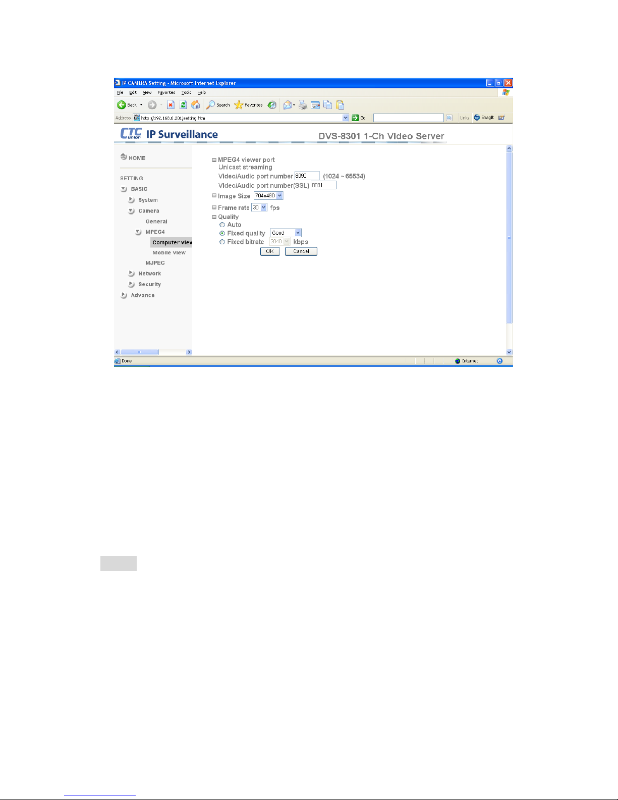
MPEG-4 viewer port (If RTSP mode is OFF)
Unicast streaming Video/Audio port number : Specify the transmission port number of the
video data. It is initially set to 8090. Specify an even number from 1024 to 65534.
Image Size:Specify the image size the network camera transmits. You can choose among
704 × 480, 352 × 240 and 176 × 120 for NTSC mode or 704 × 576, 352 × 288 and 176 × 144
for PAL mode.
Frame rate:Set the frame rate of the MPEG4 image. Selectable values are 5, 10, 15, 20, 25,
30 fps. The unit “fps” stands for “frames per second”.
Quality
Auto:The quality and bitrate will be automatically decided according to the frame rate.
Fixed Quality:The selectable values are Medium, Standard, Good, Detailed and Excellent.
Fixed Bitrate:Set the bit rate of MPEG-4 image transmission for a line. Selectable values are
64, 128, 256, 384, 512, 768, 1024, 1280, 1536 and 2048 kbps.
Note:
• The selected frame rate and bit rate are a tentative value. The actual frame rate and bit
rate may be different depending on the image size, the shooting scene or the network
condition.
Page 21
15
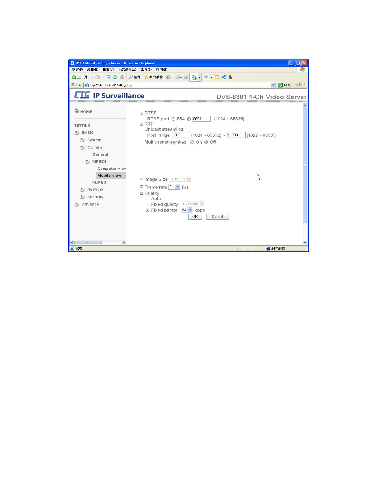
Mobile View
RTSP (If RTSP mode is ON)
RTSP port: Specify the transmission port number for RTSP streaming video. Default
value is 8554.
RTP (If RTSP mode is ON)
Unicast streaming:
Unicast streaming Video/Audio port range: Specify the transmission port range for
RTP streaming video. RTP will select a port randomly from the range.
Multicast streaming:
Multicast address: Specify the multicast server address.
Video / Audio Port: Specify the transmission port number for the video data. Initially it is
set to 10000 and 11000. Specify an even number from 1024 to 65534.
Time-To-Live: Set the maximum TTL that multicast can pass through.
Image Size: The Image size of Mobile view is fixed at 176x120.
Frame rate:Set the frame rate of the MPEG-4 image. Selectable values are 5, 10, 15, 20 fps.
The unit “fps” stands for “frames per second”.
Quality
Fixed Bitrate:Set the bit rate of MPEG-4 image transmission for a line. Selectable values
are 64, 32, and 16kbps..
Page 22
16
4.3.2.3 M-JPEG
Note:
• Motion JPEG settings are unavailable if the RTSP mode is ON, which means the MJPEG
streaming is closed.
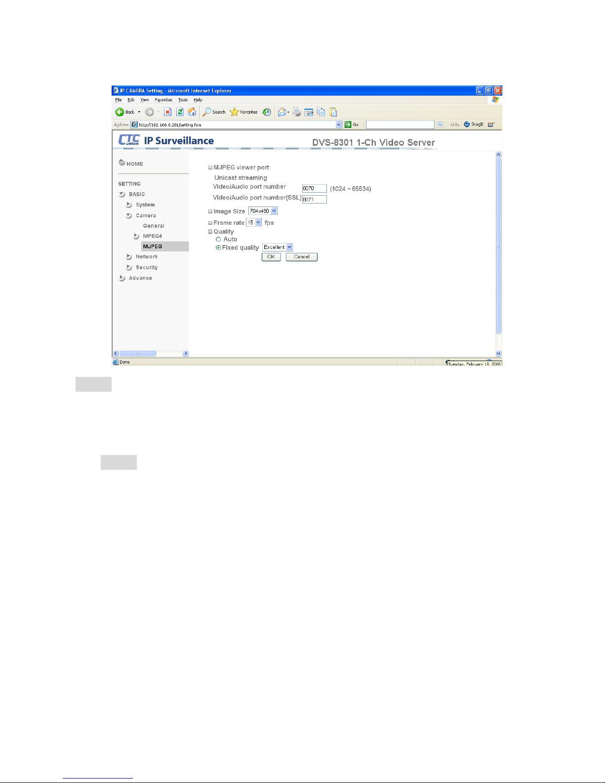
MJPEG viewer port
Unicast streaming Video/Audio port number : Specify the transmission port number for the
video data. It is initially set to 8070. Specify an even number from 1024 to 65534.
Note:
• Unicast streaming:Specify the transmission port number for the video data and audio
data used when UDP (Unicast) is selected with the TCP/UDP transmission switching
icon in the main viewer.
Image Size:Specify the image size the network camera transmits. You can choose among
704 × 480, 352 × 240 and 176 × 120 for NTSC mode or 704 × 576, 352 × 288 and 176 × 144
for PAL mode.
Frame rate:Set the frame rate of the M-JPEG image. Selectable values are 5, 10, 15 fps. The
unit “fps” stands for “frames per second”.
Quality
Auto:The quality will be automatically decided.
Fixed quality:The selectable values are Medium, Standard, Good, Detailed and Excellent.
Page 23
17
4.3.3 Network
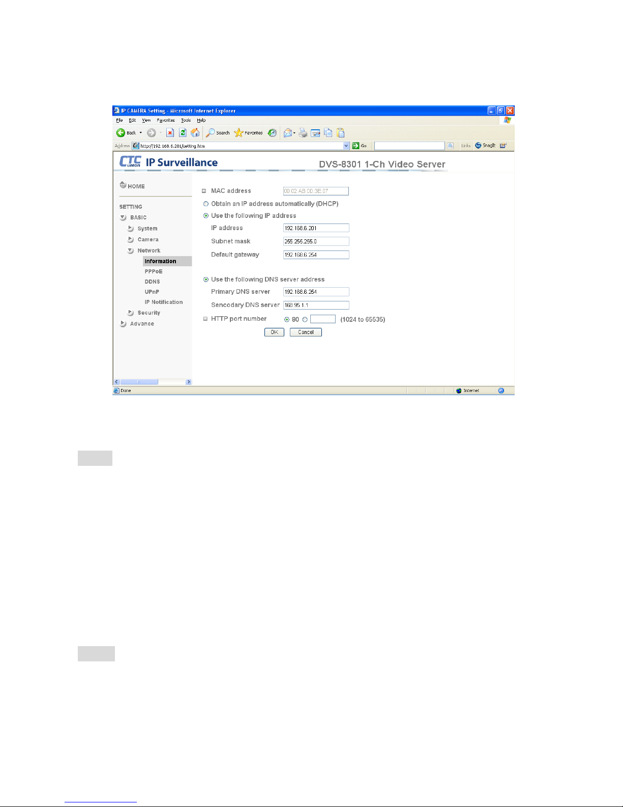
4.3.3.1 Information
MAC address:Displays the MAC address of the device.
Obtain an IP address automatically (DHCP):If a DHCP server is installed on the network, to
select this so the IP address is assigned by the DHCP server.
Note:When you set Obtain an IP address automatically (DHCP), make sure that the DHCP
server is working on the network.
Use the following IP address:Select this when a fixed IP address is set.
IP address:Enter the IP address of the device.
Subnet mask:Enter the subnet mask.
Default gateway:Enter the default gateway.
Use the following DNS server address:Select this when you set the fixed address as the IP
address of DNS server.
Primary DNS server:Enter the IP address of the primary DNS server.
Secondary DNS server:Enter the IP address of the secondary DNS server, if necessary.
HTTP port number:Select 80 in general situations. If you want to use a port number other
than 80, select the text box and enter a port number between 1024 and 65535.
Note:When you have set the HTTP port number to a number other than 80 on the Network
setting page or in the Setup Program, access the device by typing the IP address of the device
on the web browser as follows:
Example: when HTTP port number is set to 2000 Æ http://192.168.0.100:2000/
Page 24
18
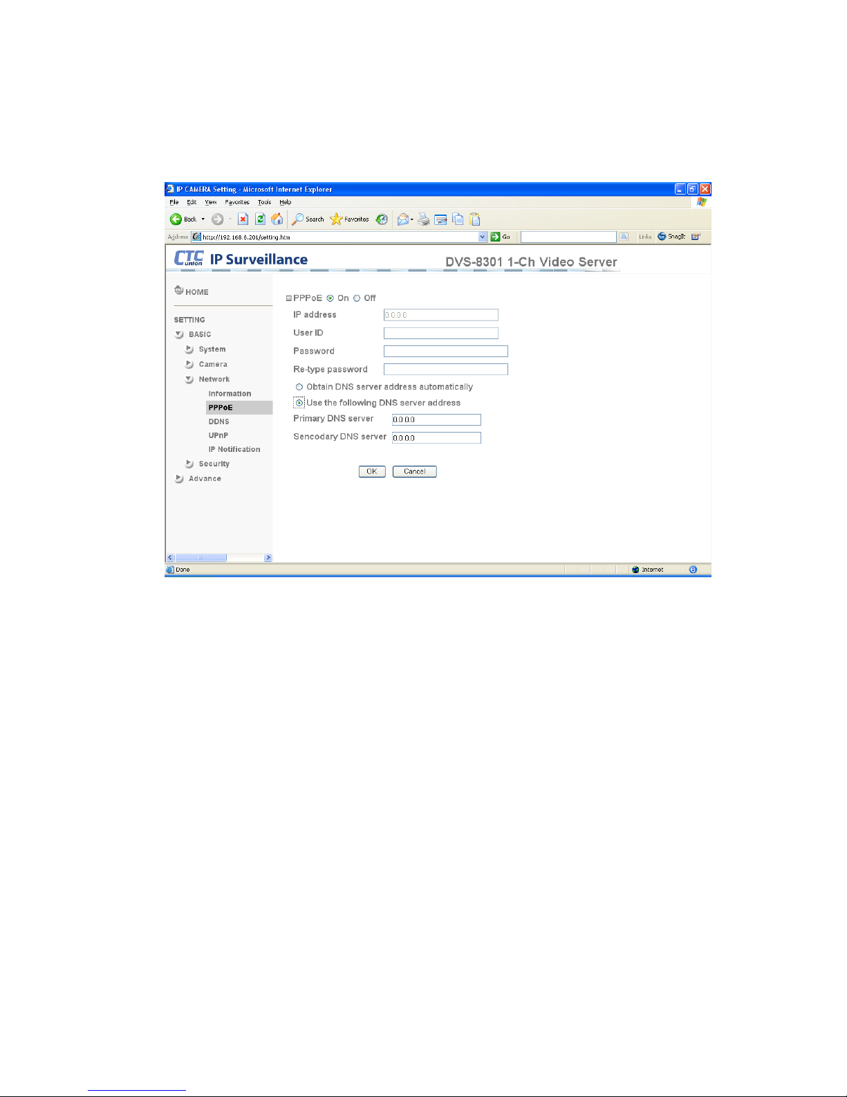
4.3.3.2 PPPoE
Use this setting when you connect the device through PPPoE (Point -to- Point Protocol over
Ethernet). PPPoE connection is a protocol that is widely used in xDSL (digital subscriber line
such as ADSL, VDSL or SHDSL) as the authentication and connection system.
IP address:The IP address obtained from the PPPoE connecting to the network.
User ID:Enter the user ID for authentication necessary for PPPoE connections. Type it up to
64 characters.
Password:Enter the password for authentication, if necessary, for PPPoE connections. It
may be up to 32 characters.
Re-type password:Re-type the password to confirm.
Obtain DNS server address automatically:Select this to obtain the address of DNS server
automatically.
Use the following DNS server address:Select this when you set a fixed address as the IP
address of DNS server.
Primary DNS server:Enter the IP address of the primary DNS server.
Secondary DNS server:Enter the IP address of the secondary DNS server.
Page 25
19
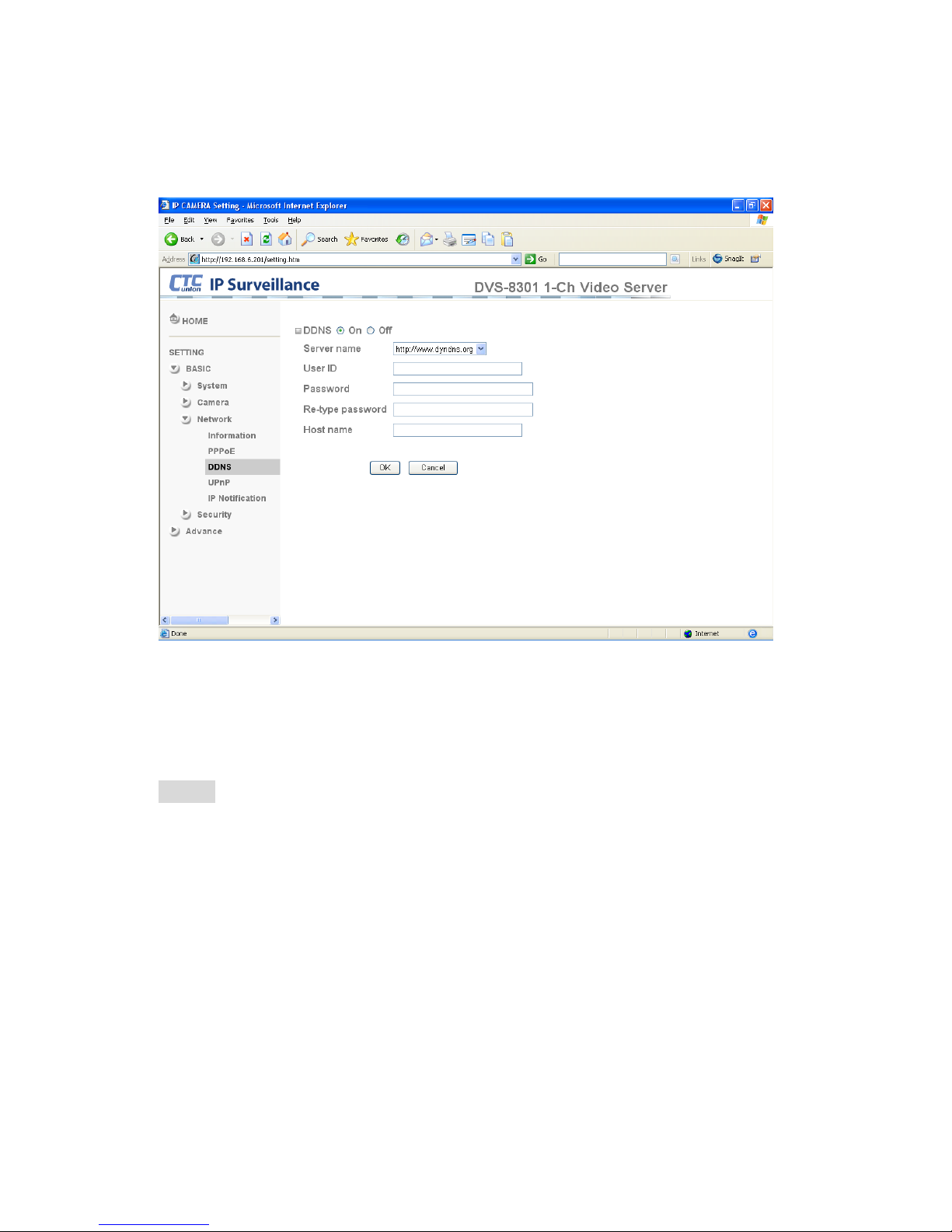
4.3.3.3 DDNS
DDNS or Dynamic DNS allows this device to register its IP address with a DDNS
service provider. This allows accessing this device by using a real name, rather than
having to remember the device's IP address.
Server name:Choose the DDNS Server from the list.
User ID:Enter the user ID for authentication necessary for DDNS connections. Type it up to
64 characters.
Password:Enter the password for authentication necessary for DDNS connections. Type it
up to 32 characters.
Re-type password:Re-type the password to confirm.
Host name:Enter the host name that is registered to the DDNS server.
Note:
• When you want to use this DDNS function, you need to register an account with a
DDNS service provider first.
Page 26
20
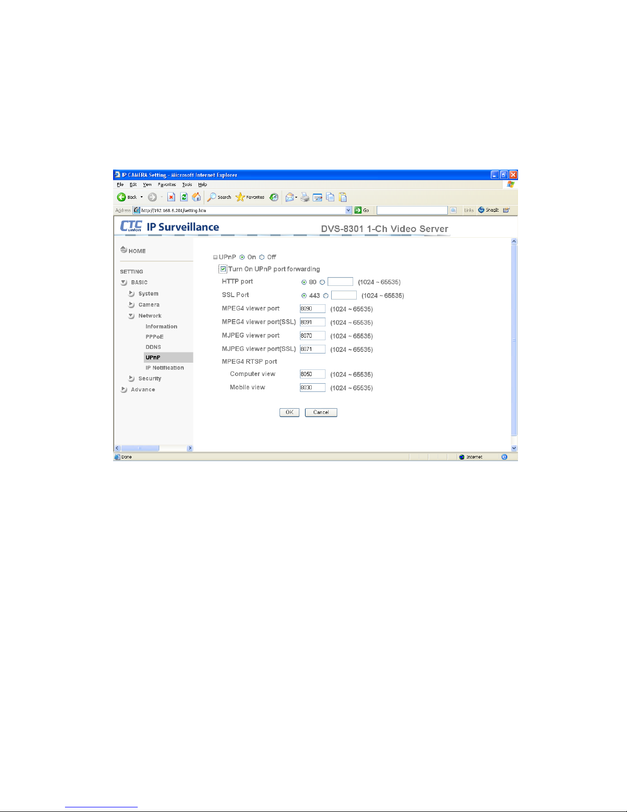
4.3.3.4 UPnP
This device includes support for UPnP (Universal Plug 'n Play), which is enabled by default.
If also enabled on your computer, the device will automatically be detected and a new icon
will be added to “My Network Places.” UPnP provides port forwarding for opening a port in a
router or firewall in a private network in order to let a party from the outside world contact a
user device inside the firewalled network.
HTTP port:Enter the HTTP port number. The default HTTP port is 80.
SSL port: Enter the SSL port number. The default SSL port is 443.
MPEG-4 viewer port:Enter the MPEG-4 viewer port number. The default MPEG-4 viewer
port is 8090.
MPEG-4 viewer port(SSL): Enter the MPEG-4 SSL viewer port number. The default is 8091.
M-JPEG viewer port:Enter the M-JPEG viewer port number . The default M-JPEG viewer port
is 8070.
MJPEG viewer port(SSL): Enter the M-JPEG SSL viewer port number. The default is 8071.
MPEG-4 RTSP port: Enter the MPEG-4 RTSP port number. The default value is 8050 for
computer view, 8030 for mobile view.
Page 27
21
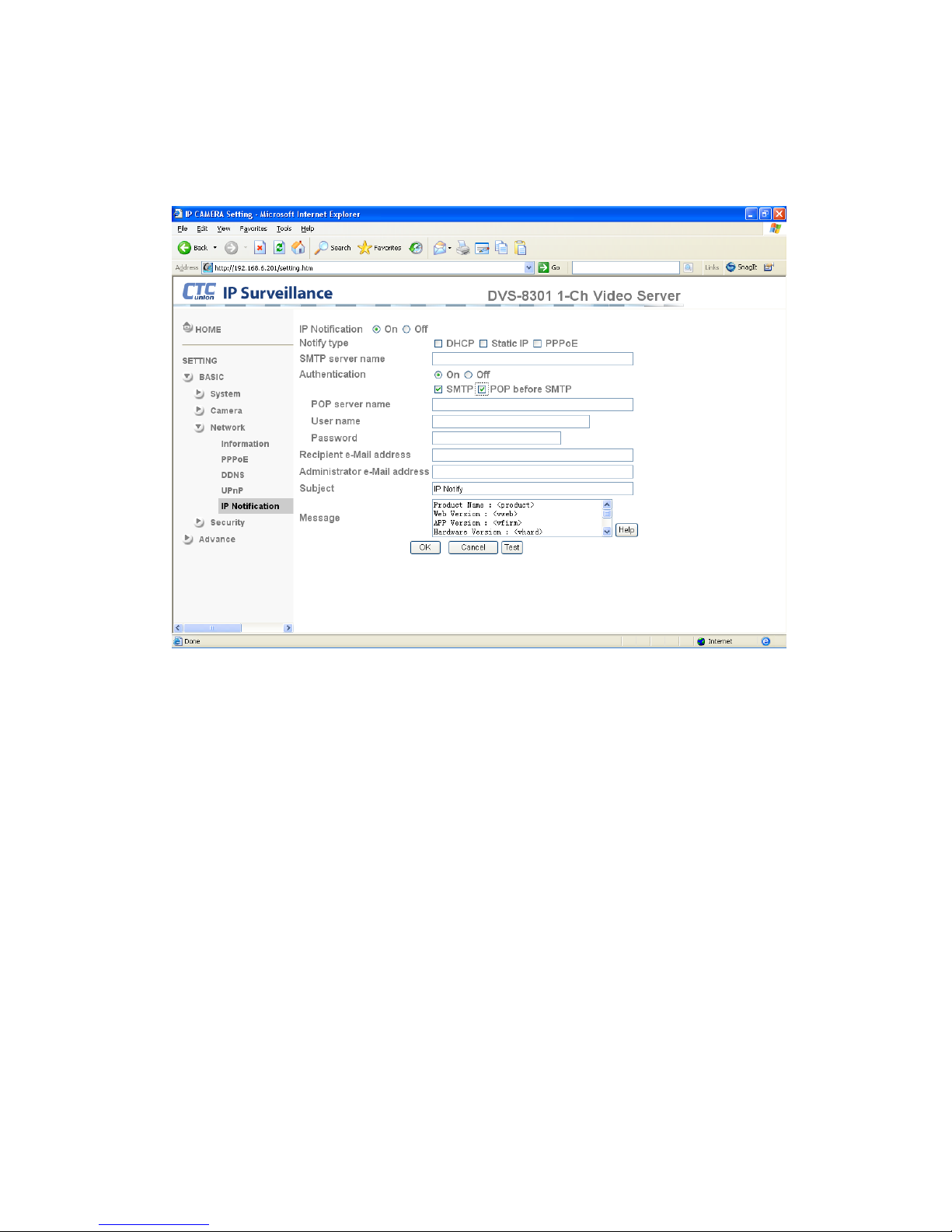
4.3.3.5 IP Notification
When IP notification is set to On, you can send an e-mail notification of the completion of
the network settings.
Notify type:Select type of DHCP, Static IP and PPPoE setting that will notify.
SMTP server name:Type the SMTP server name up to 64 characters, or the IP address of
the SMTP server used to relay the email notification messages.
Authentication:Select the authentication required when you send an email.
Off: Select if no authentication is necessary when an email is sent.
On: When authentication is necessary to relay email, select one of the authentication methods
from the followings.
SMTP: Select if SMTP authentication is necessary when an e-mail is sent.
POP before SMTP: Select if POP before SMTP authentication is necessary when an e-mail is
sent.
Page 28

22
Note:When you set to On, be sure to select either or both SMTP or/and POP before SMTP.
POP server name:It is necessary when the POP before SMTP is selected in Authentication.
Type the POP (receiving mail) server name up to 64 characters, or type the IP address of the
POP server. This setting is necessary when the SMTP server which sends e-mails performs
authentication using the POP user account.
User name, Password:Type the user name and Password of the user who has the mail
account. This setting is necessary when the SMTP server which sends e-mails performs
authentication.
Recipient e-mail address:Type the recipient e-Mail address up to 64 characters. You can
specify up to three recipient E-mail addresses.
Administrator e-mail address:Type the Administrator e-Mail address up to 64 characters.
This address is used for reply mail and sending system messages from the SMTP server.
Subject:Type the subject/title of the e-Mail up to 64 characters, with respect to mail which is
sent according to the IP notification.
Message
Type the text of the E-mail up to 384 characters. Default value provides network information
including IP, Port, MAC, Model, Firmware Version and Web Version.
Page 29
23
4.3.4 Security
4.3.4.1 Accounts
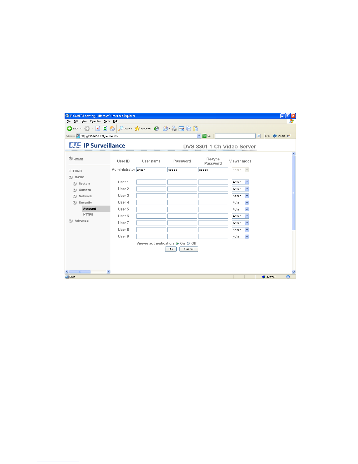
The device default account and password setting is “admin/admin”. This means anyone
might gain access to the device including the configuration as long as the IP address is known.
It is necessary to assign a password if the device is intended to be accessed by others. Use
this menu to set the user names and passwords of Administrator and up to 9 different users
(User 1 to User 9), and the access right of each user.
User name:Set a user name between 5 and 16 characters.
Password:Set a password between 5 and 16 characters.
Re-type password:Re-type the password to confirm.
Viewer Mode:Set a user to Admin, Operator or Viewer mode.
Viewer authentication:If Off, allows any viewer direct access to Live View without any
authentication.
Page 30
24
4.3.4.2 HTTPS
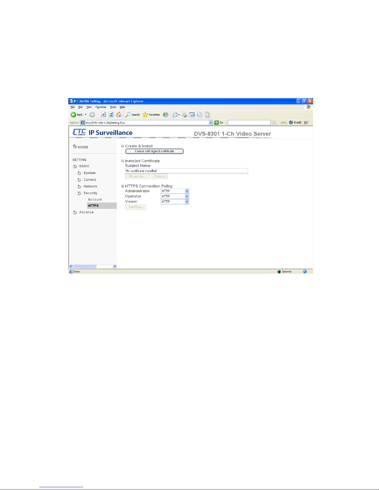
HTTPS is a URI scheme used to indicate a secure HTTP connection. It is syntactically
identical to the http:// scheme normally used for accessing resources using HTTP.
Using an https: URL indicates that secure HTTP is to be used, but with a different default
TCP port (443) and an additional encryption/authentication layer between the HTTP and TCP.
You can use the IP camera through HTTPS easily by using https:// instead of http://.
Create & Install: Create a self-signed certificate for HTTPS to recognize.
Installed Certificate: Display or remove the properties of the installed certificate.
HTTPS Connection Policy: Set HTTPS connection policy for different level of users.
Page 31
CHAPTER 4 How to Use
25
4.4 Advanced Settings
4.4.1 PTZ Control
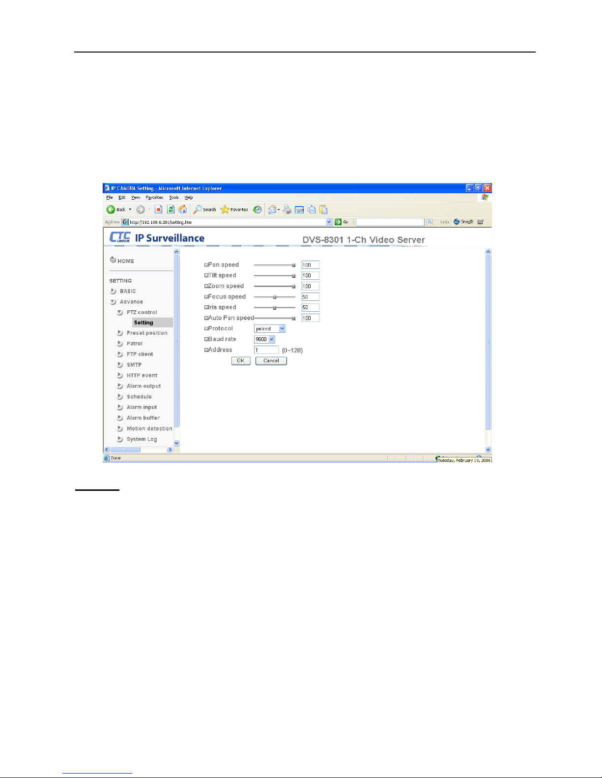
This section explains Pan, Tilt, Zoom, Focus, Iris and Auto Pan speed control settings, as
well as the Protocol, Baud rate and Address which depend on the Speed Dome control
module.
Setting
Pan speed:Use it to move bar from 0 to 100.
Tilt speed:Use it to move bar from 0 to 100.
Zoom speed:Use it to move bar from 0 to 100.
Focus speed:Use it to move bar from 0 to 100.
Iris speed:Use it to move bar from 0 to 100.
Auto Pan speed:Use it to move bar from 0 to 100.
Protocol:Include Vtrec, Pelcod, Pelcop, Lilin and Dynacolor.
Baud rate:Include 9600, 4800, 2400 and 1200.
Address:Type it from 0 to 128.
Page 32
CHAPTER 4 How to Use
26
4.4.2 Preset Position
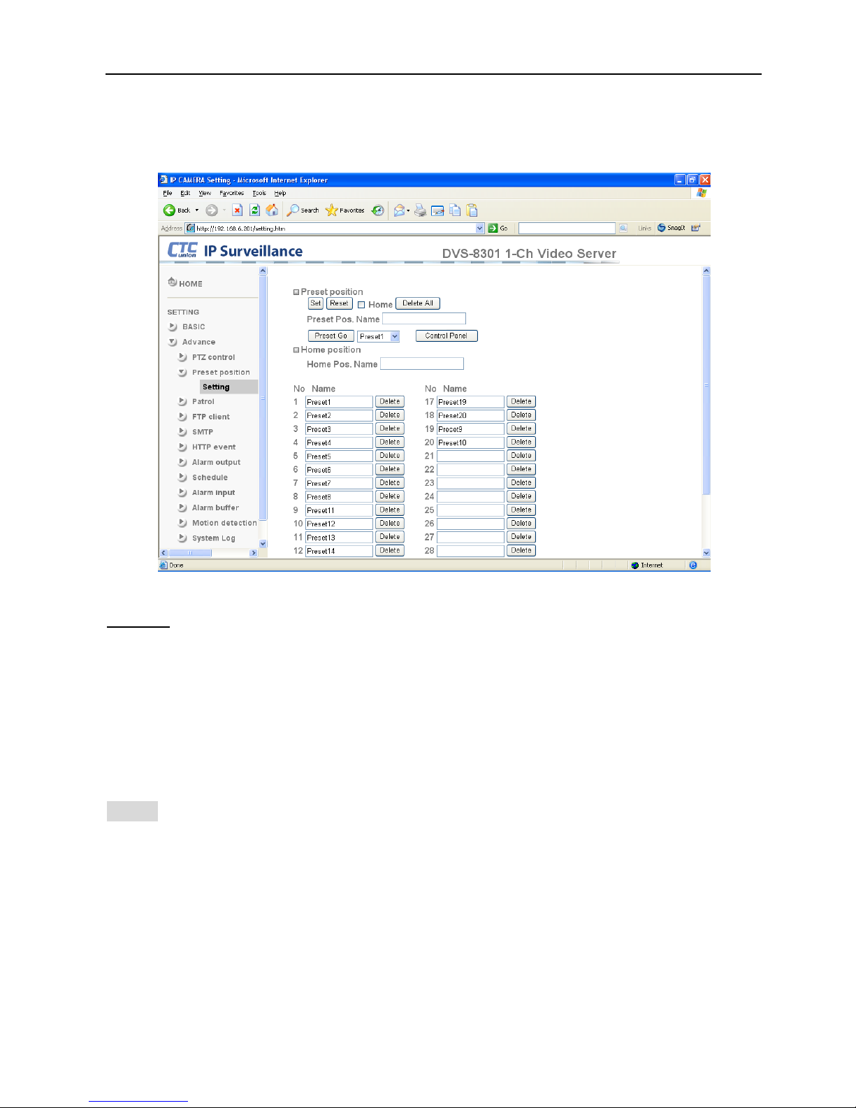
In this section, up to 32 Pan / Tilt and Zoom positions can be saved, as well as the home
position, which the device faces to when the power is turned on.
Setting
Set:Use it to save the camera position to a preset number.
Carry out the following steps.
1. Move the camera to the position to be saved while you are checking the image with the
main console.
2. Write the preset position name in Preset Pos. Name text box.
3. Click the SET. The camera position is saved.
4. If want to set this position as home position, click Home option on. Click the SET. The
camera position is saved as home position.
Note:Setting the new Home position will replace any previously set Home position.
Reset:When writing the preset position name in Preset Pos. Name text box, press Reset to
clear typed characters.
Delete All:Be careful! When pressing Delete All. All Preset Position information will be
deleted.
Delete:Select a preset number from 1 to 32 in the list box. Use it to delete a specific number
preset position setting.
Page 33
27
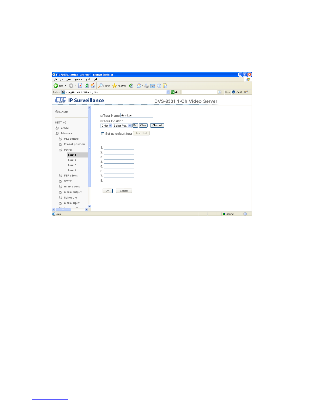
4.4.3 Patrol
There are four patrol tours to set for composing different preset positions. Each one lists up to
8 positions which can be programmed, and the will camera move to those programmed
positions sequentially. The camera stops when it moves to the last preset position.
Tour name:Rename the tour name.
Tour position
Order:There are 8 orders to select for camera directions.
Select Pos.:There are up to 32 preset positions to choose for each order.
Recall:When you click Recall, the camera moves to position of the selected preset number.
Clear:When setting specific preset number position to tour, click Clear to clear this direction
information.
Clear All:Be careful! When you click Clear All, it will clear this tour all information out.
Set:Use it to save the camera position to a preset number.
Set as default tour:Click it on to set this tour as default.
Tour Start:Click Tour Start, and the camera moves on patrol tour.
Tour Stop:While the camera is moving on patrol tour, click Tour Stop to stop the patrol tour.
Carry out the following steps:
1. Click “Order” to choose one of eight orders.
2. Click Select Pos. to set the preset position.
3. Click the SET. The tour position is saved.
4. Follow the steps to set the other orders.
5. Click the OK to save the tour.
Page 34
28
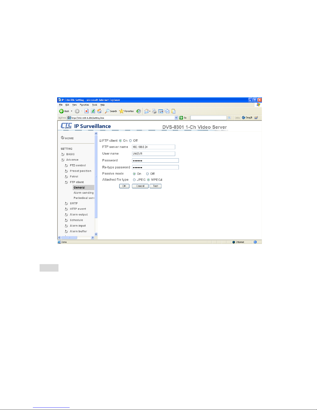
4.4.4 FTP Client
Use this setup page to configure capturing and sending of images to an FTP server. By using
FTP client function, you can send a video file which has been shot and recorded triggered by
the external sensor input, alarm buffer or with the built-in motion detection function to FTP
server. FTP client setting menu is composed of three tabs, General, Alarm sending and
Periodical sending.
4.4.4.1 General
FTP client function:To activate the FTP client function, select On. The FTP client setting
page appears. When you do not wish to use the FTP client function, select Off.
Note:The frame rate and operability on the main viewer may decrease while a file is being
transmitted by the FTP client function.
FTP server name:Type the FTP server name to upload still images up to 64 characters, or
the IP address of the FTP server.
User name:Type the user name for the FTP server.
Password:Type the password for the FTP server.
Retype password:To confirm the password, type the same characters as you typed in the
Password box.
Passive mode:Set whether you use the passive or active mode of FTP when connecting to
FTP server. Select On to connect to FTP server using the passive mode.
Attached file type:Set attached file type to JPEG or MPEG-4.
Page 35
29
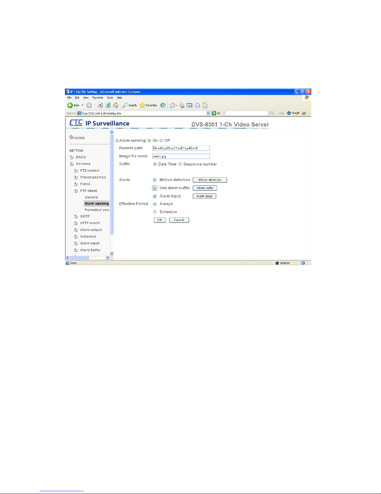
4.4.4.2 Alarm Sending
This function is used to forward the image and audio file to the specified FTP server when an
alarm is detected by an external sensor input or by the built-in motion detection function.
Select On to send the image and audio file to FTP server triggered by alarm detection.
Remote path:Type the path to the destination on the FTP server, up to 64 characters.
Image file name:Type the file name you want to assign to the images when sending to the
FTP server. You can use up to 10 alphanumeric characters, - (hyphen) and _ (underscore) for
naming. Please do not leave spaces in the name.
Suffix:Select a suffix to add to the file name:
Date & time: The date & time suffix is added to the Image file name. The date/time suffix
consists of lower two-digits of year (2 digits), month (2 digits), date (2 digits), hour (2
digits), minute (2 digits), second (2 digits), and consecutive number (2 digits), thus
14-digit number is added to the file name.
Sequence number: A consecutive number of 10 digits between 0000000001 and
4294967295 and two fixed digits 00 are added to the Image file name.
Page 36

30
Motion Detection:Click it On to use Motion Detection function as a trigger. You can then
setup the motion detection function page.
Note:
• Motion Detection works only when the Video mode is set to MPEG-4 and the
Cropping is set to Off.
Alarm Buffer:Select Use alarm buffer when you forward the image/ audio of before and
after the alarm detection (pre-alarm, post-alarm). If you do not select it, only the image of the
moment of the alarm detection is forwarded. Click Alarm buffer to display the Alarm buffer
setting menu. For details, see “Setting the Alarm Buffer — Alarm buffer setting page".
Alarm Input:
Select the connected alarm.
Sensor input1: The external sensor which is connected to sensor input1 of the camera
I/O port.
Effective period:Set the period when the periodical sending is effective.
Always:The periodical sending is always effective.
Schedule:You can specify the period when the periodical sending is effective in the
schedule setting in the other section. Click Schedule and the setting menu for the effective
period is displayed.
Page 37
31
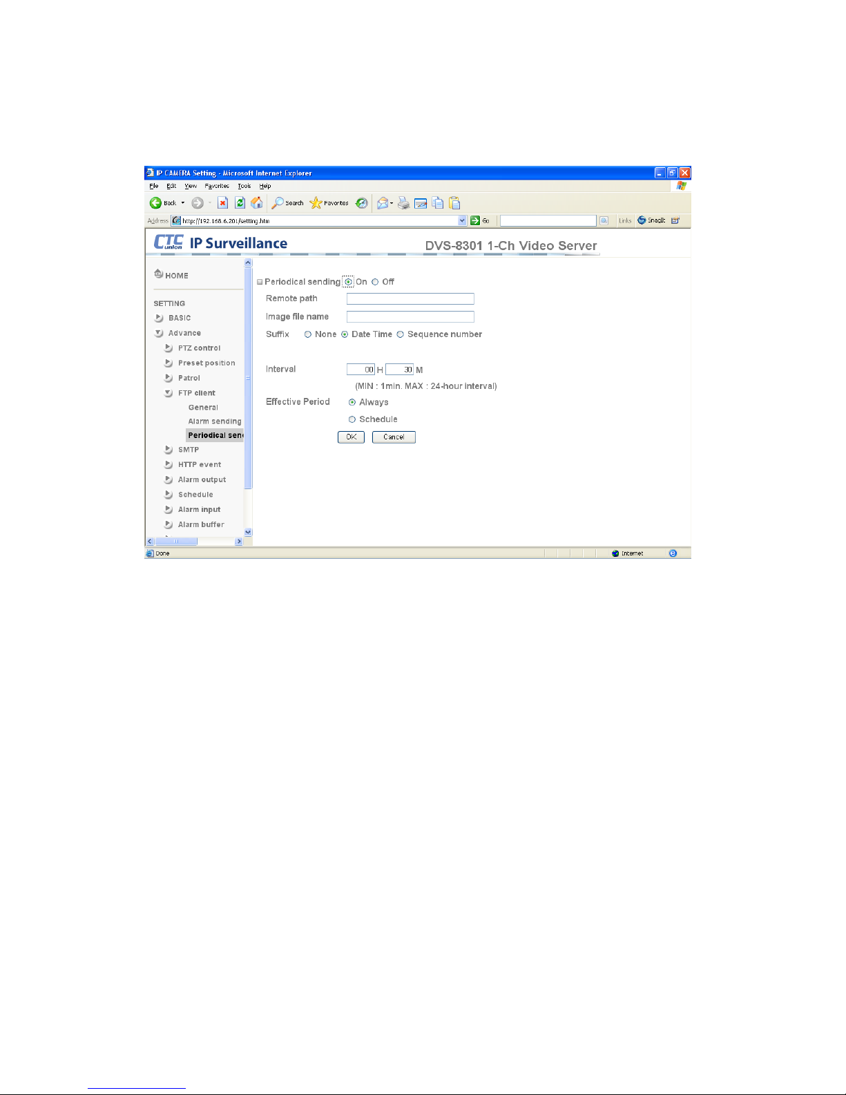
4.4.4.3 Periodical Sending
You can setup to send an image file to FTP server periodically by selecting On to send the
image file to FTP server triggered with setting period.
Remote path:Type the remote path, up to 64 characters.
Image file name:Type the file name of the image sent to FTP server with up to 10
alphanumeric characters, - (hyphen) and _ (under score).
Suffix:Select a suffix to be added to the file name sent to FTP server.
None:The name of the sent file will be the Image file name.
Date & time:The date & time suffix is added to the Image file name. The date & time suffix
consists of lower two-digits of year (2 digits), month (2 digits), date (2 digits), hour (2 digits),
minute (2 digits) and second (2 digits), and consecutive number (2 digits), thus 14-digit
number is added to the file name.
Sequence number:A consecutive number is added to the Image file name.
Sequence number clear:Click Clear and the suffix of the sequence number returns to 1.
Interval:Set the interval to send the periodic image. Minimum value is 1 minute and maximum
value is 24 hours.
Effective period:Set the period during which the periodical sending is effective.
Always:The periodical sending is always effective.
Schedule:You can specify the period when the periodical sending is effective in the
schedule setting in the other section. Click Schedule and the setting menu for the
effective period is displayed.
Page 38
32
4.4.5 SMTP
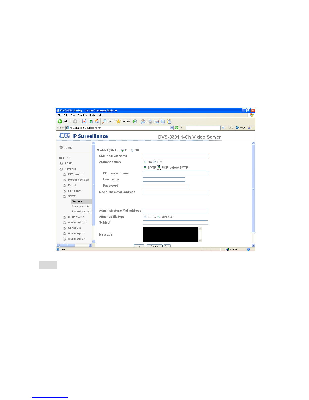
Use the SMTP setting page when you want to send an image via e-mail. By using the Mail
(SMTP) function, you can send a mail with attached image which has been shot triggered by
the external sensor input or with the built-in motion detection function. The image file can also
be sent periodically. E-Mail (SMTP) setting menu is composed of three tabs, General, Alarm
sending and Periodical sending.
4.4.5.1 General
Select On when you wish to use the SMTP function. The common setting options are
displayed below. If you do not wish to use the e-Mail (SMTP) function, select Off and click OK.
Note:
• During transmission of an image file via mail, the frame rate and operation performance
of the monitor image of the main viewer may be reduced.
• While the camera video mode is set to MPEG-4, the image of the composite video
signal output from the video output connector of the camera may be distorted during
mail transmission.
• You cannot send an audio file by using the mail sending function.
SMTP server name:Type the SMTP server name, up to 64 characters, or the IP address of
the SMTP server.
Authentication:Select the authentication method required when you send an email.
Off: Select if no authentication is necessary when an email is sent.
On: When authentication is necessary to send an e-mail, select one of the authentication
methods from the following.
Page 39

33
SMTP: Select if SMTP authentication is necessary when an e-mail is sent.
POP before SMTP: Select if POP before SMTP authentication is necessary when an e-mail is
sent.
Note:
• When you set to On, be sure to select either or both SMTP or/and POP before SMTP.
POP server name:This is necessary when the POP before SMTP is selected in
Authentication. Type the POP (receiving mail) server name, up to 64 characters, or type the
IP address of the POP server. This setting is necessary when the SMTP server which sends
e-mails performs authentication using the POP user account.
User name, Password:Type the user name and Password of the user who has the mail
account. This setting is necessary when the SMTP server which sends e-mails performs
authentication.
Recipient e-mail address:Type the recipient e-Mail address, up to 64 characters. You can
specify up to three recipient E-mail addresses.
Administrator e-mail address:Type the Administrator e-Mail address, up to 64 characters.
This address is used for reply mail and sending system messages from the SMTP server.
Attached File Type: Select to attach the file as JPEG or MPEG-4.
Subject:Type the subject/title of the e-Mail, up to 64 characters. With respect to mail which is
sent according to the alarm detection when Alarm sending of the alarm tab is set to On, the
characters standing for the sensor type are added to the subject.
Message:Type the text of the E-mail, up to 384 characters. (A line break is equivalent to 2
characters.)
Page 40
34
4.4.5.2 Alarm Sending
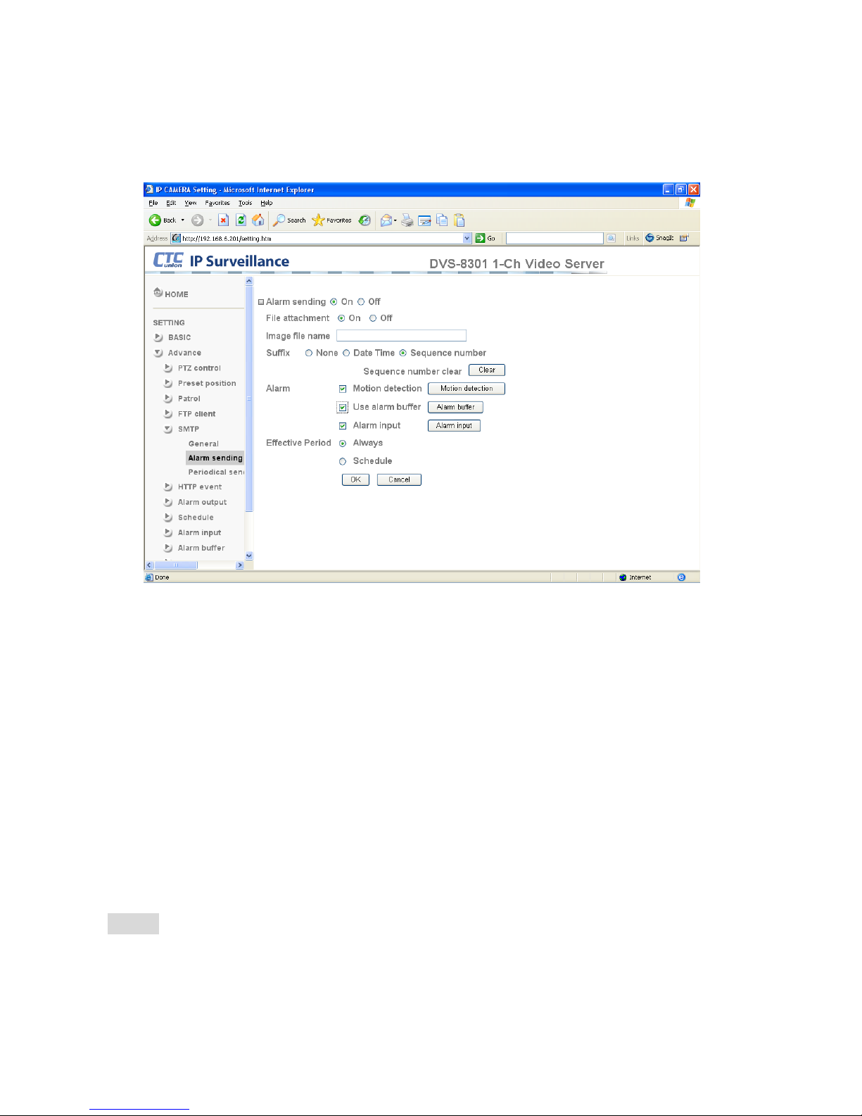
Use this setting page to trigger the email sending in response to an alarm detected by the
external sensor input or by the built-in motion detection function.
Alarm sending:Select On to set up send mail in response to the alarm detection.
File attachment:Set whether an image file is attached to the mail sent or not. When On is
selected, the image file made by the settings below is attached. When Off is selected, only the
message is sent.
Image file name:Type the file name you want to assign to the image to attach a mail. You
can use up to 10 alphanumeric, - (hyphen) and _ (underscore) for naming.
Suffix:Select a suffix to add to the file name:
None: No suffix is added. The Image file name is assigned to the image to be sent via an
e-Mail.
Date & time: The date & time suffix is added to the Image file name. The date/time suffix
consists of lower two-digits of year (2 digits), month (2 digits), date (2 digits), hour (2
digits), minute (2 digits), second (2 digits), and consecutive number (2 digits), thus
14-digit number is added to the file name.
Sequence number: A consecutive number of 10 digits between 0000000001 and
4294967295 and two fixed digits 00 is added to the Image file name.
Motion Detection:Click this to use the Motion Detection function as a trigger. You can then
setup the motion detection function page.
Note:
• Motion Detection works only when the Video mode is set to MPEG4 and Cropping is
set to Off.
Page 41

35
Alarm Buffer:Select Use alarm buffer when you want to forward the image/ audio of before
and after the alarm detection (pre-alarm, post-alarm). If you do not select this, only the image
of the moment of the alarm detection is forwarded. Click Alarm buffer to display the Alarm
buffer setting menu. For details, see “Setting the Alarm Buffer — Alarm buffer setting Menu on
page.
Alarm Input:
Select the connected alarm.
Sensor input1: The external sensor which is connected to sensor input1 of the camera
I/O port.
Effective period:Set the period when the periodical sending is effective.
Always:The periodical sending is always effective.
Schedule:You can specify the period when the periodical sending is effective in the
schedule setting in the other section. Click Schedule and the setting menu for the effective
period is displayed. (“Setting the Schedule — Schedule setting Menu” page).
Page 42
36
4.4.5.3 Periodical Sending
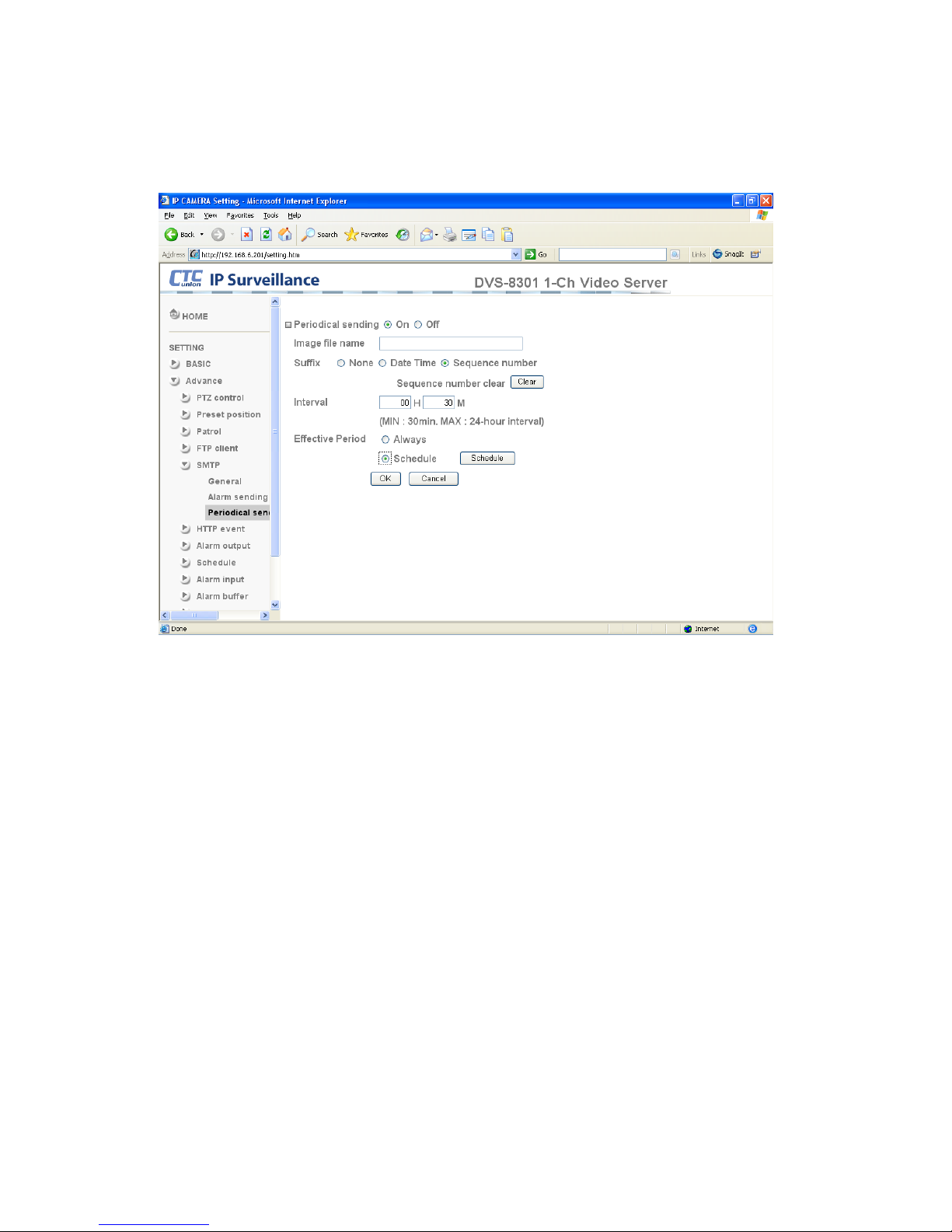
You can setup to send an image file by SMTP server periodically by selecting On to send
the image file by SMTP server linked with setting period.
Image file name:Type the file name of the image sent by SMTP up to 10 alphanumeric
characters, - (hyphen) and _ (under score).
Suffix:Select a suffix to be added to the file name sent by SMTP.
None:The name of the sent file will be the Image file name.
Date & time:The date & time suffix is added to the Image file name. The date & time suffix
consists of lower two-digits of year (2 digits), month (2 digits), date (2 digits), hour (2 digits),
minute (2 digits) and second (2 digits), and consecutive number (2 digits), thus 14-digit
number is added to the file name.
Sequence number:A consecutive number is added to the Image file name.
Sequence number clear:Click Clear and the suffix of the sequence number returns to 1.
Interval:Set the periodical sending interval. Minimum value is 30 minutes and maximum
value is 24 hours.
Effective period:Set the time period when the periodical sending is effective.
Always:The sending function is always active.
Schedule:You can specify the period when the periodical sending is effective in the
schedule setting in the other section. Click Schedule and the setting menu for the effective
period is displayed. (“Setting the Schedule — Schedule setting Menu” page).
Page 43
37
4.4.6 HTTP Event
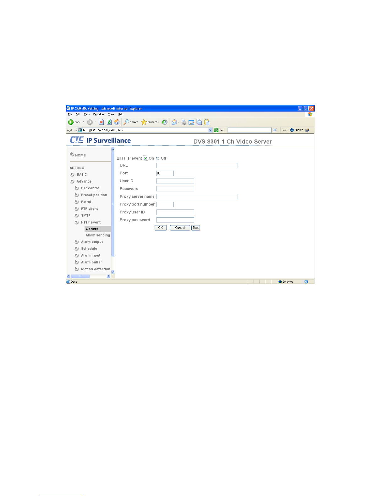
Use this menu to setup capturing and sending images to an HTTP server. By using HTTP
client function, you can send the specified CGI-BIN message linked with the external sensor
input or with the built-in motion detection function to HTTP server. HTTP client setting menu is
composed of two tabs, General and Alarm sending.
4.4.6.1 General
HTTP event: Set up the HTTP server URL, port, user id, password, and proxy server
settings.
Page 44
38
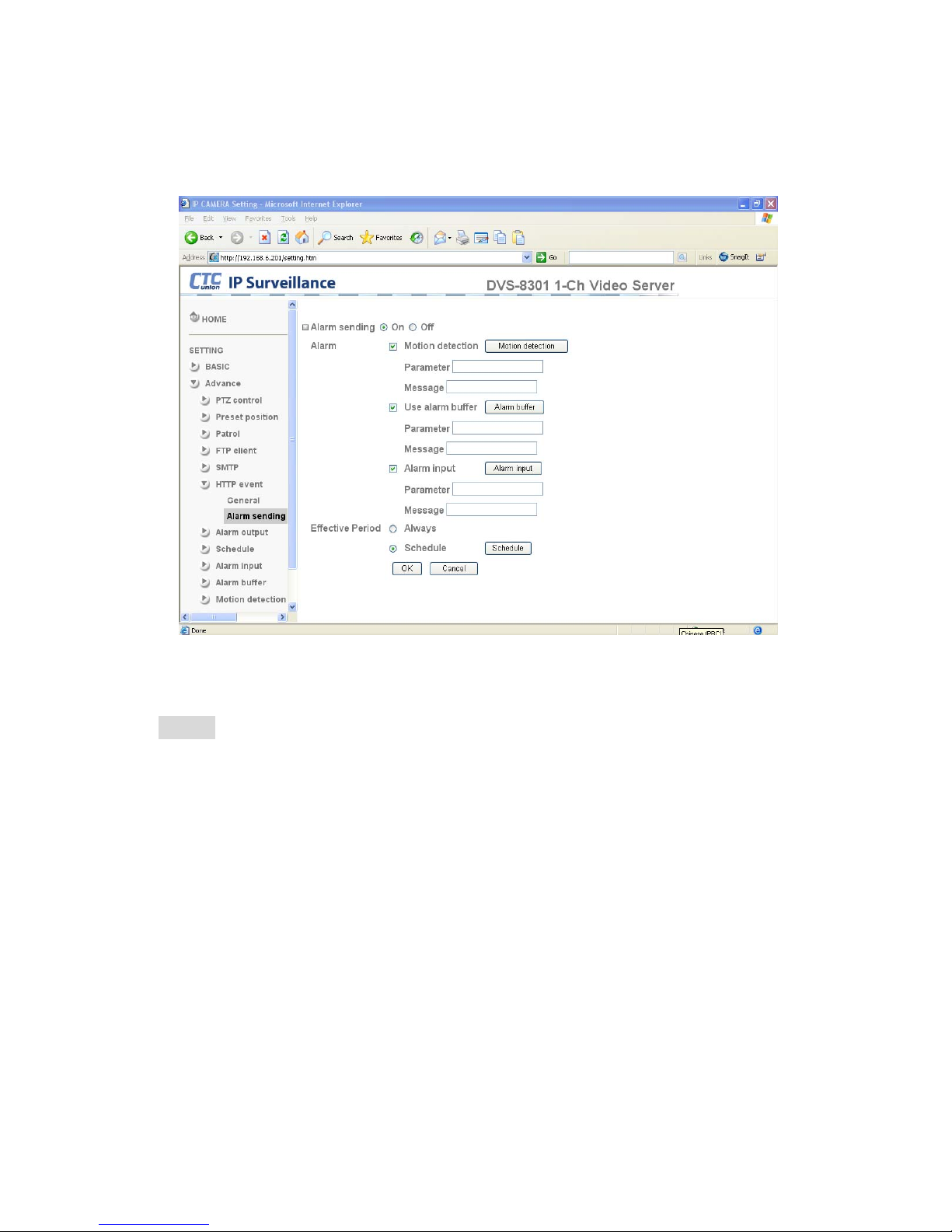
4.4.6.2 Alarm sending
Use this page to setup the alarms used to trigger actions such as sending mail, sending to
FTP server or sending to HTTP server.
Alarm sending:Select On to set the alarm detection action.
Motion Detection:Click On to use Motion Detection function as a sensor. You can set the
details on the motion detection function page.
Note:
• Motion Detection works only when the Video mode is set to MPEG4 and Cropping is
set to Off.
Alarm Buffer:Select Use alarm buffer when you wish to forward the image/ audio of before
and after the alarm detection (pre-alarm, post-alarm). If you do not select it, only the image of
the moment of the alarm detection is forwarded. Click Alarm buffer to display the Alarm buffer
setting menu. For details, see “Setting the Alarm Buffer — Alarm buffer setting Menu on page.
Alarm Input:
Select the connected alarm.
Sensor input1: The external sensor which is connected to sensor input1 of the camera
I/O port.
Effective period:Set the period when the periodical sending is effective.
Always:The periodical sending is always effective.
Schedule:You can specify the period when the periodical sending is effective in the
schedule setting in the other section. Click Schedule and the setting menu for the
effective period is displayed.
Page 45
39
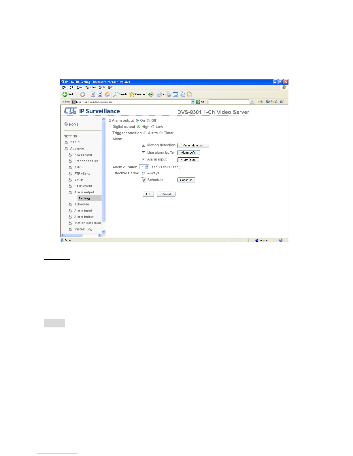
4.4.7 Alarm Output
When you click Alarm output on the Advance mode menu, the Alarm output setting menu
appears. You can configure the alarm out of I/O port on the rear of the device linked to the
alarm detection and the timer.
Setting
Alarm output:To activate the Alarm output function, select On. The basic setting options are
displayed below. When you do not use the Alarm output function, select Off.
Trigger condition:Select the mode of the Alarm output function. You can choose “Alarm” or
“Timer”.
Alarm:
Controls alarm output by synchronizing with an external sensor input or the built-in activity
detection function.
Motion Detection:Click On to use Motion Detection function as a sensor. You can setup the
motion detection function page.
Note: Motion Detection works only when the Video mode is set to MPEG4 and the
Cropping is set to Off.
Use alarm buffer :Select Use alarm buffer when you forward the image/ audio of before and
after the alarm detection (pre-alarm, post-alarm). If you do not select it, only the image of the
moment of the alarm detection is forwarded. Click Alarm buffer to display the Alarm buffer
setting menu. For details, see “Setting the Alarm Buffer — Alarm buffer setting" Menu page.
Page 46

40
Alarm Input: Control the external alarm input of I/O port on the rear of the device triggering
the FTP and SMTP sending function. Click Alarm Input to display the Alarm input setting
menu. For details, see “Setting the Alarm Input — Alarm input setting Menu” page.
Alarm duration:There are up to 60 second options to choose for alarm duration interval.
Effective period:Set the period when the periodical sending is effective.
Always:The periodical sending is always effective.
Schedule:You can specify the period when the periodical sending is effective in the schedule
setting in the other section. Click Schedule and the setting menu for the effective period is
displayed.
Timer: Controls alarm output by the timer. When clicking “Timer”, a sub window pops up. Set
the Recording time of Pre-alarm period and Post-alarm period. The recording time may be up
to 5 seconds.
Schedule:You can specify the period when the periodical sending is effective in the schedule
setting in the other section. Click Schedule and the setting menu for the effective period is
displayed.
Page 47
41
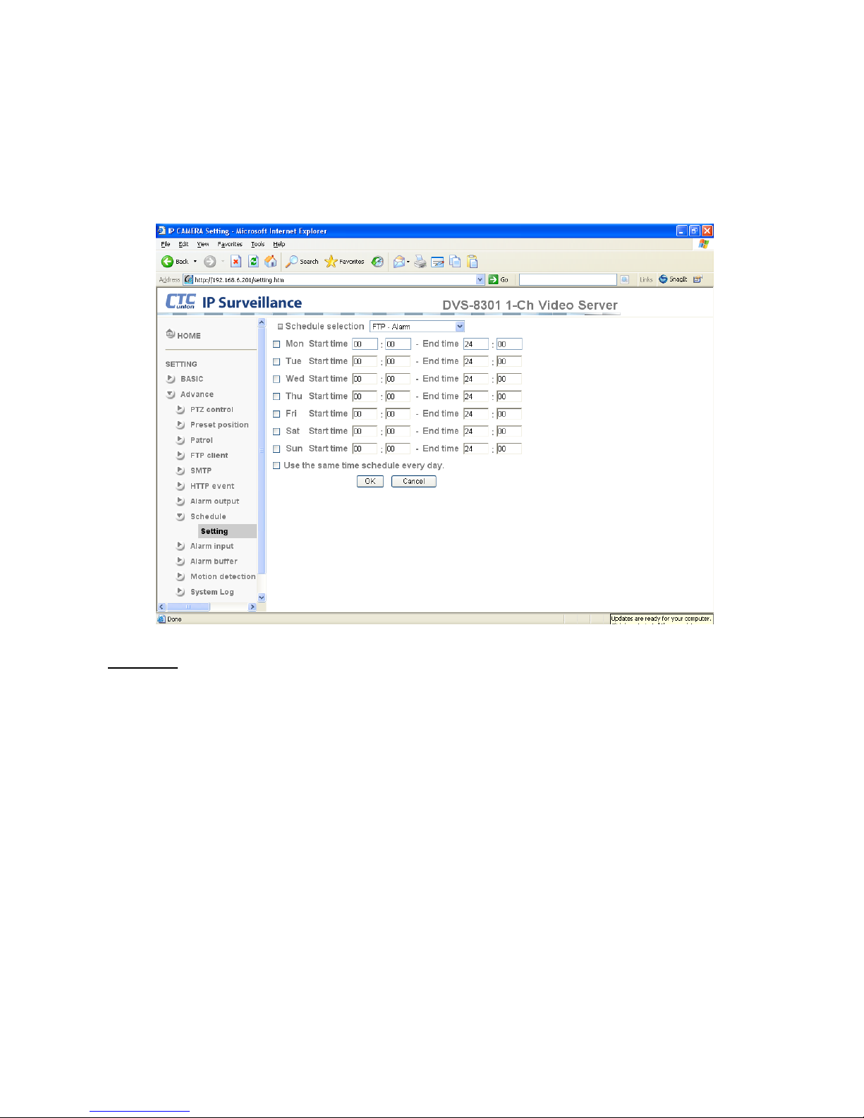
4.4.8 Schedule
When you click Schedule on the Advance mode menu, the Schedule setting menu appears.
This is the same menu as the setting menu which is displayed when you click Schedule to set
Effective period and Schedule in FTP client setting menu, e-Mail (SMTP) setting menu, Alarm
out setting menu and so on. Example: When setting e-Mail (SMTP) (the alarm sending) in the
Schedule setting menu.
Setting
Schedule selection
Select the list box to specify the schedule you want to set. e-Mail (SMTP) – Alarm, e-Mail
(SMTP) – Periodical, FTP – Alarm, FTP – Periodical, HTTP event – Alarm, Alarm output –
Alarm or Alarm output – Timer, can be selected.
Mon (Monday) to Sun (Sunday)
The time period on the right of the checked day is the effective period of the schedule.
Start time, End time
Specify the Start time and the End time.
Use the same time schedule every day
When this is checked, the Start time and End time set to Mon (Monday) are applied to all
days. In this case, the Start time and End time of the other days than Mon (Monday) cannot
be input.
Page 48
Chapter#4 How to Use
42
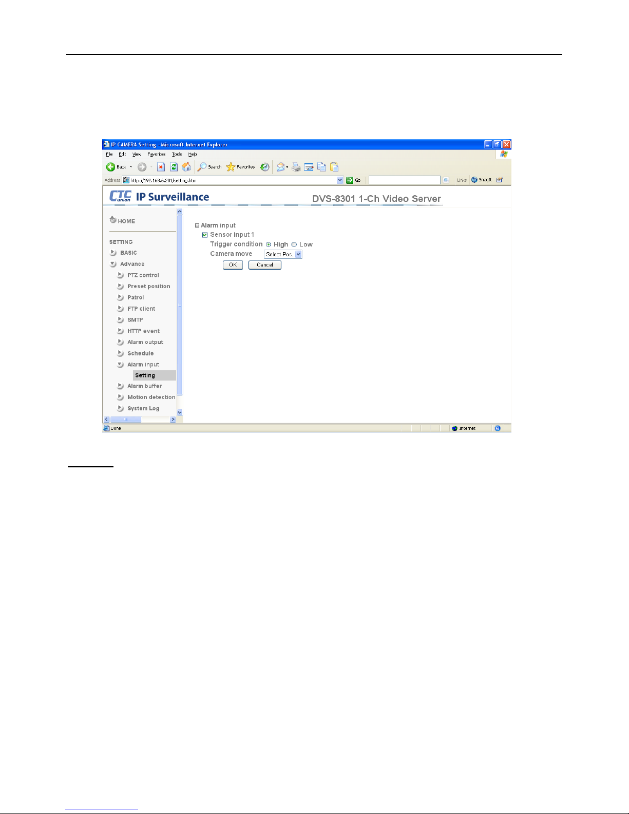
4.4.9 Alarm Input
When you click Alarm Input on the Advance mode menu, the Alarm input setting menu
appears. You can set in this menu to control the external alarm input of I/O port on the rear of the
device triggering the FTP and SMTP sending functions.
Setting
Sensor input 1:Click On to use external sensor which is connected to sensor input1 of the
camera I/O port.
Trigger condition: Select “High” or “Low”.
Camera move: Pull down the window to select the camera preset position.
Page 49
Chapter#4 How to Use
43
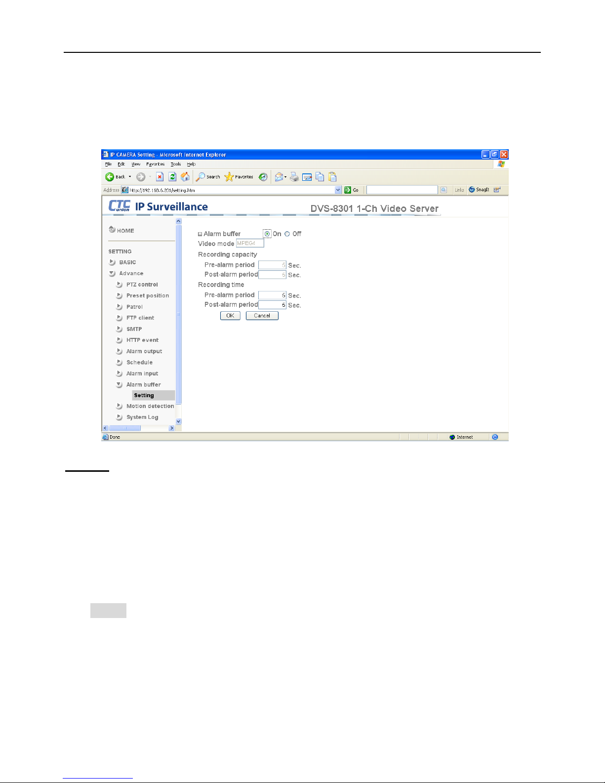
4.4.10 Alarm Buffer
On this page you can set the Pre-alarm image and audio (the image and audio before the alarm
detection) and the Post - alarm image and audio. These can be set when Alarm sending FTP
client setting menu or Image memory setting menu is set to On, and also when Use alarm
buffer is selected.
Setting
Video Mode: The video mode of alarm buffer is MPEG-4.
Alarm buffer:To activate the Alarm buffer function, select On. The basic setting options are
displayed below. When you do not use the Alarm output function, select Off.
Recording capacity
Pre-alarm period:Display the maximum recording capacity of image/audio before the
alarm detection.
Post-alarm period:Display the maximum recording capacity of image/audio after the alarm
detection.
Recording time
Set the recording time for the Pre-alarm image/audio and Post alarm image/audio.
Pre alarm period:Type it with recording time of the image/audio before the alarm detection.
Post alarm period:Type it with recording time of the image/audio after the alarm detection.
Note:
• The value of Recording capacity differs depending on Image size, bit rate (for MPEG4)
and Image quality (for MPEG4 and MJPEG) in the camera setting menu.
Page 50
Chapter#4 How to Use
44
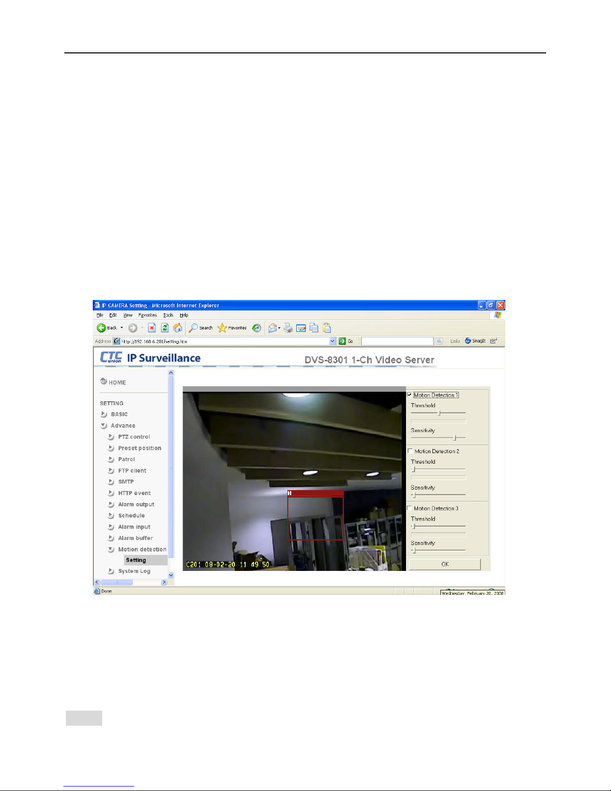
4.4.11 Motion Detection
When you click Motion Detection on the Advance mode menu, the Motion Detection setting
menu appears. There are three Motion Detection functions which act as sensors and can be set
for different detecting zones. Each one has Threshold and Sensitivity inputs which you can
adjust to specific zone sequentially. Motion Detection function can support triggering for FTP,
SMTP and Alarm output for capturing and sending images or starting alarm output.
If you do not wish to use the Motion Detection function, click it Off and press OK.
Motion Detection 1:Click On to use Motion Detection 1 function as a sensor. You can adjust
and move the detecting zone by using mouse.
Motion Detection 2:Click On to use Motion Detection 2 function as a sensor. You can adjust
and move the detecting zone by using mouse.
Motion Detection 3:Click On to use Motion Detection 3 function as a sensor. You can adjust
and move the detecting zone by using mouse.
Threshold:You can use the tool bar to set up-limit value. When detecting zone signals are over
setting value, it would carry on assigned work.
Sensitivity:You can use the tool bar to set down-limit value. When detecting zone signals are
over setting value, it would carry on assigned work.
Carry out the following steps:
1. Click On Motion Detection 1, choose one of eight orders.
2. A detecting zone 1 appears. Use mouse to adjust and move the zone boundaries and
position.
3. Use tool bar to set Threshold and Sensitivity value.
4. Follow the steps to set the other Motion Detection.
5. Click OK to save the setting.
Note: Warning! Motion Detection function doesn’t work with Patrol function at the same time.
Page 51
Chapter#4 How to Use
45
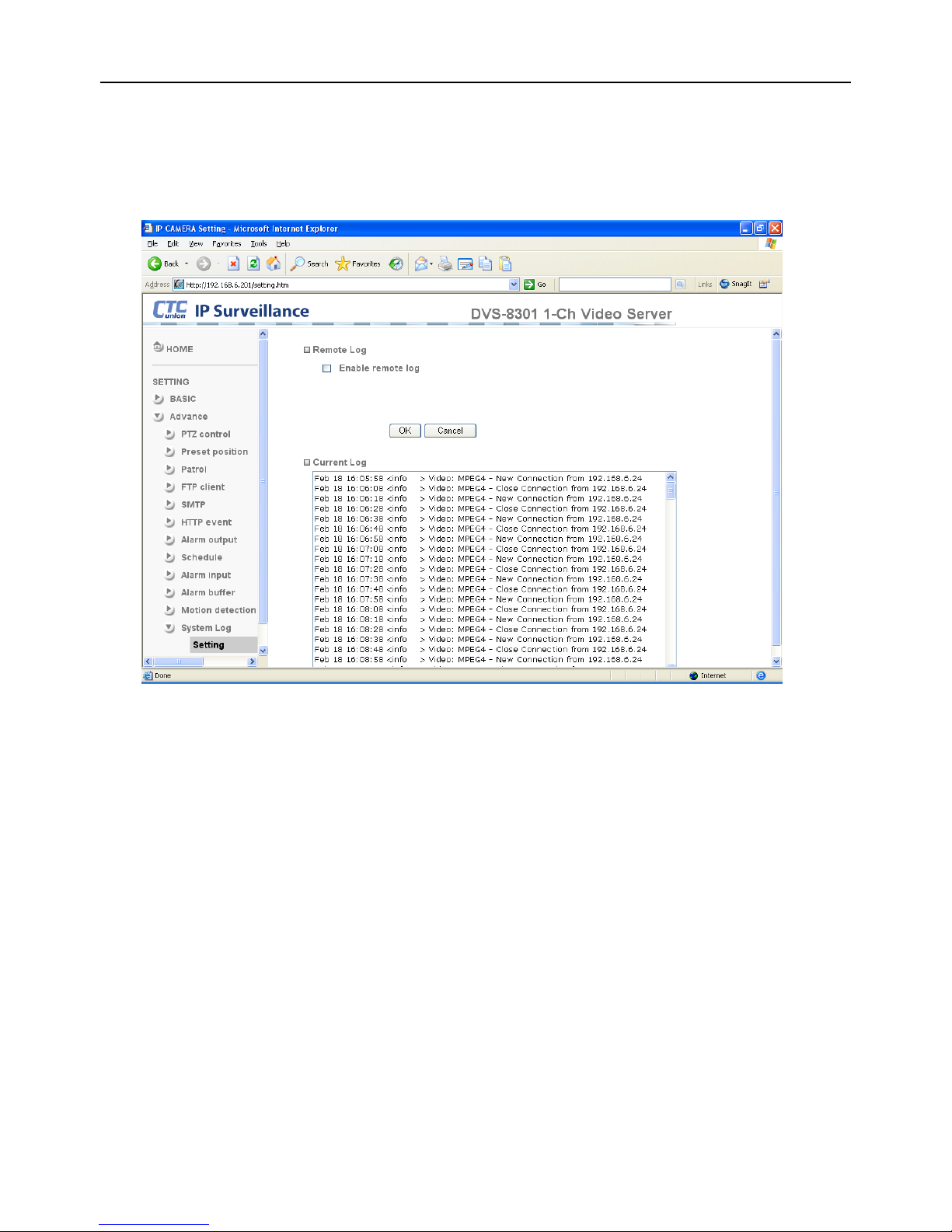
4.4.12 System Log
The System Log function allows users to review any changes and events that have happened.
The system starts logging automatically after started.
Remote Log: Enables user to send the log data to a specified log server.
Page 52

Page 53

DVS Series
CTC Union Technologies Co., Ltd.
Far Eastern Vienna Technology Center
(Neihu Technology Park)
8F, No.60, Zhouzi Street
Neihu District, Taipei 114, Taiwan
Phone:(886) 2.2659.1021 Fax:(886) 2.2799.1355
E-mail: [email protected] Url:http://www.ctcu.com
 Loading...