

Page 1
1
Installation Instruction of
CTC DIY 3D Printer
Focus on high-end science and technology,focus on 3D printing
Zhuhai CTC Electronics Co.,Ltd.
www.ctcprinter.com
Page 2

2
Introduction
This DIY 3D printer can be used under different voltages according to different regions,
please confirm the voltage of your region before using this printer (110V or 220V)
Printer maintenance conducted by customer is required after it is used for a period of time.
Frequent correct maintenance can be extend the using lifetime of the printer.
1.Safety Issues
In order to obtain the best 3D printing effect, we do not recommend you to use consumables
of other brand other than the exclusive consumables provided by CTC company. The
maintenance and repairs caused by using consumables not provided by Zhuhai CTC Electronic
Co.,Ltd is not valid for the product warranty of our company.
When it is printing or has just finished printing, the temperature of the module, nozzle,print
bed or the other parts within the printer body is very high, please do not touch these parts
with your hand.
When the printer is power on, it is forbidden to touch the power supply, power port cable, or
motherboard cable with hand or conductive articles.
It is forbidden to print directly on the heating bed. A piece of Borosilicate glass plate is
required to be put on the bed under this condition.
2. Materials and Parts
Note: All parts are listed in appendix, please refer to List of Materials for CTC DIY 3D
Printer as attached.
2.1 Assembling of Frames
Page 3
3
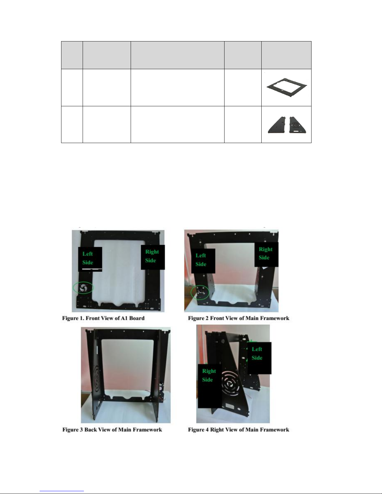
Frame parts are as above,use
○
3
M3 washer,
○
4
nut and
○
6
M3 x16mm screws to assemble
each board for assembling a main framework. The installation direction must be comply with
the following figures (Figure 1 to Figure 5). The connection of each board and assemblies are
shown in Figure as below:
No.
Item Name
Specification
Quantity
Picture
A1
XZ Frame
EUY-MO1
1
A2 &
A3
Left side &
Right side
frame
A2-EUY-MO2(Left)
A3-EUY-MO3(Right)
1
Page 4
4
2.2 Assembling of Fan
Accessories:
○
23
Fan x1;
○
5
M3x30mm screws x4;
○
3
M3 washer x 4;
○
4
nut x4;
○
9
Fan
support column x 4
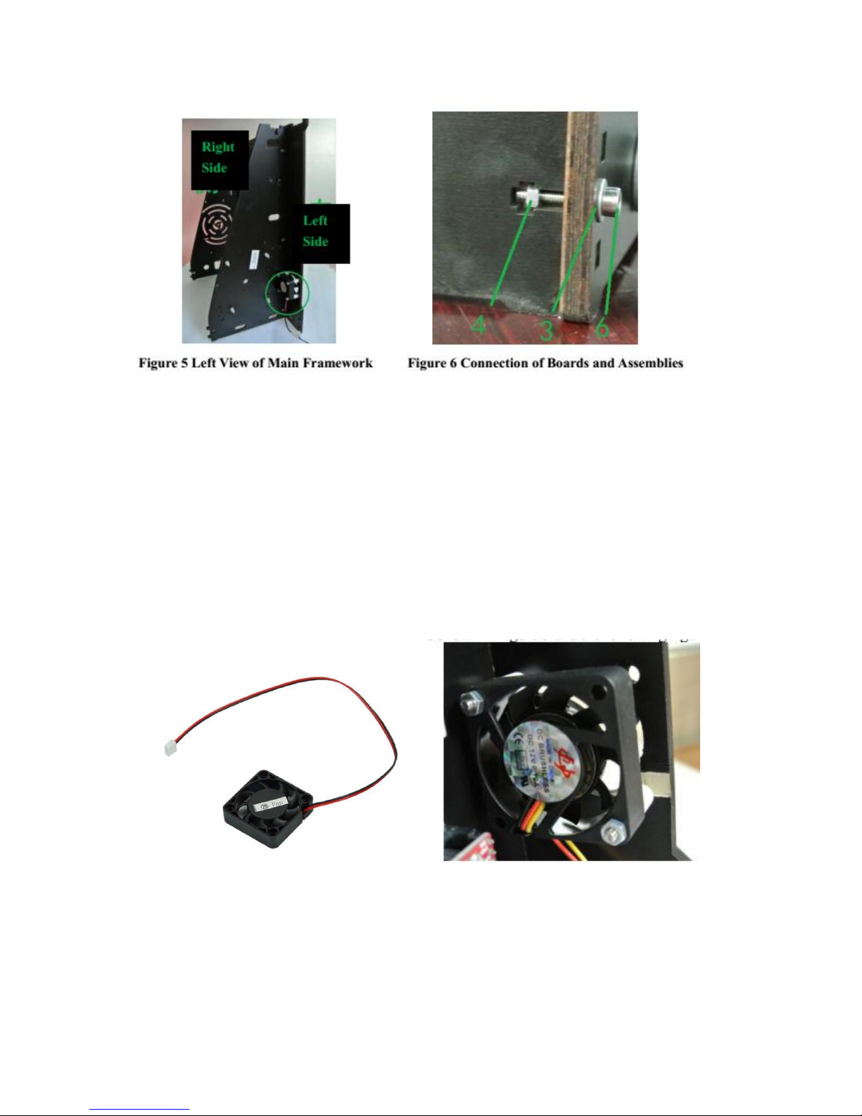
Install cooling fan to the back of the left cooling outlet of A1 board with
○
5
M3 x 30mm
screws,
○
3
M3 washers and
○
4
nuts. The fan label should face to the back of A1 board. It is
required to install 4pcs of
○
9
Fan support column. Please note the installation direction as shown in
Figure as below.
2.3 Assembling of Power Supply
Accessories:
○
25
Power supply x1;
○
7
M3x8mm screw x3;
○
20
3D power switch x 1;
○
6 M3 x16mm screw x2;
○
5
M3x30mm screws x4;
○
4
nut x4
Page 5
5
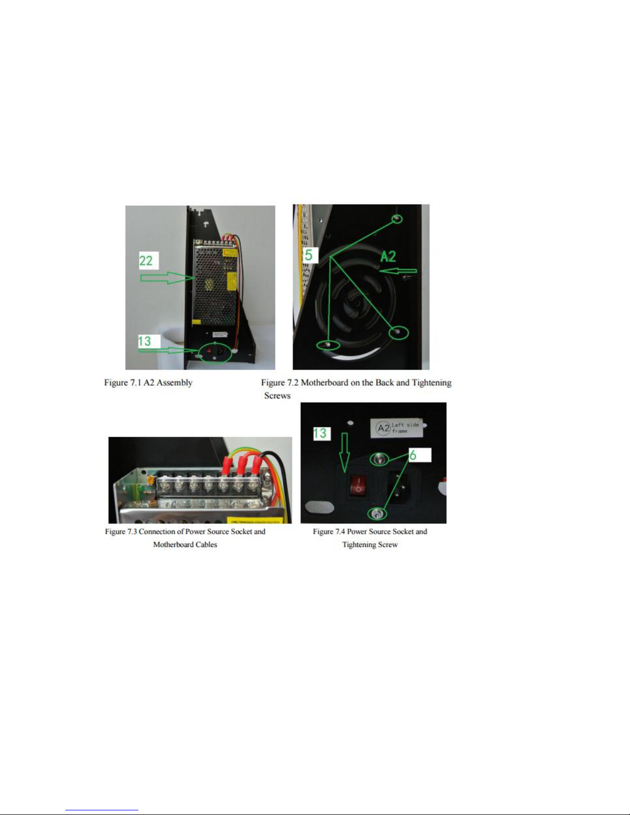
Fix the
○
25
power supply on the A2 board on the right sight of the frame with 3pcs
○
7
M3x8mm screws, then fix
○
20
3D power switch onto A2 board by using
○
6 M3
x16mm screws,
○
4
nuts and
○
3
M3 washers. The connection of 3D power switch and power
supply cables are shown in the following figures.
2.4 Assembling of Motherboard
Accessories:
○
30
Motherboard ;
○
7
M3x8mm screw x 4;
○
11
Motherboard Support Column
x 4
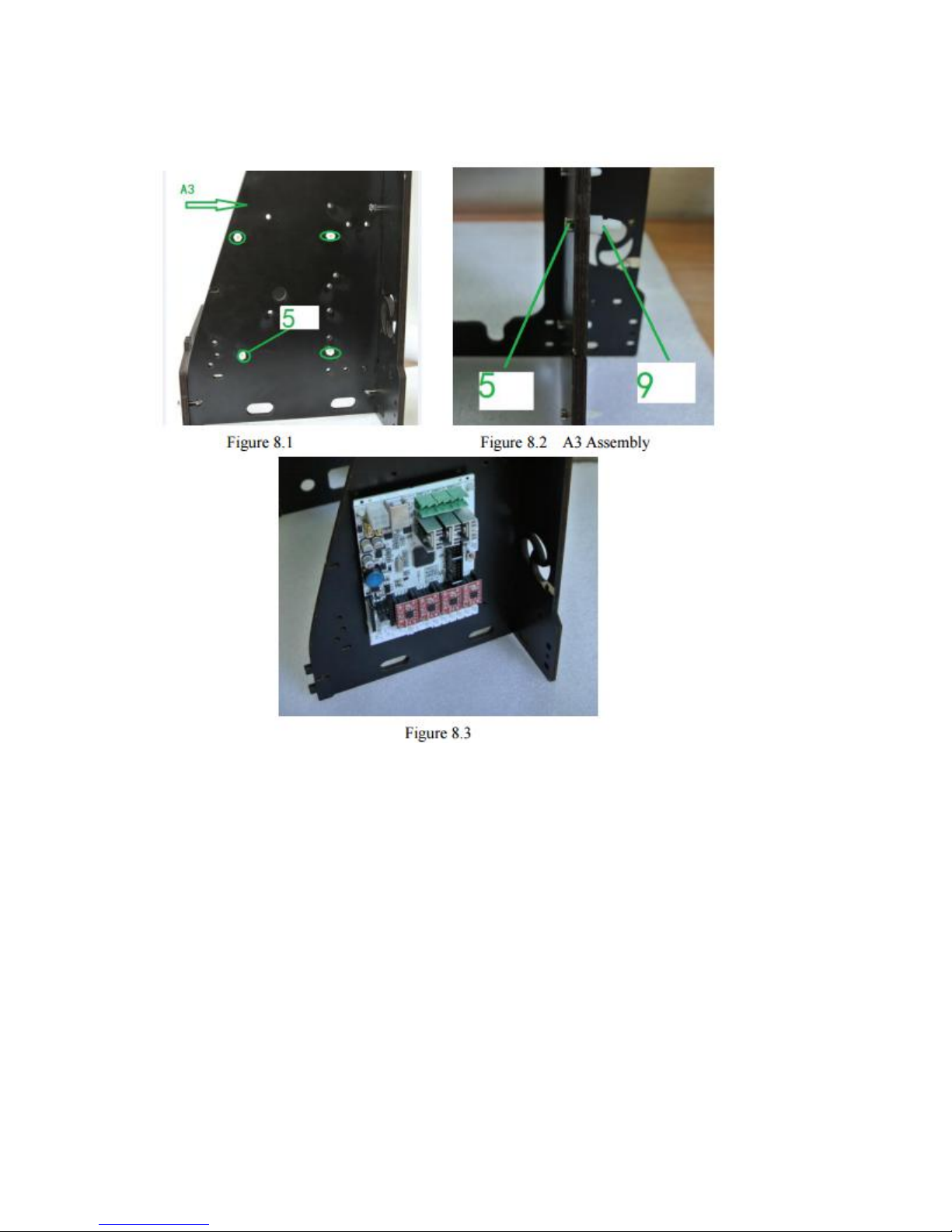
As shown in the figures below, insert 4 pcs support columns into the A3 board on
the left side of the framework with 4pcs
○
7
M3x8mm screws. The follow Figure
8.3, press
○
30
motherboard with its holes in alignment with the 4 columns. Pay
Page 6
6
attention to the installation direction.
The main Structure’s Installation and Connections of
Power cable ports
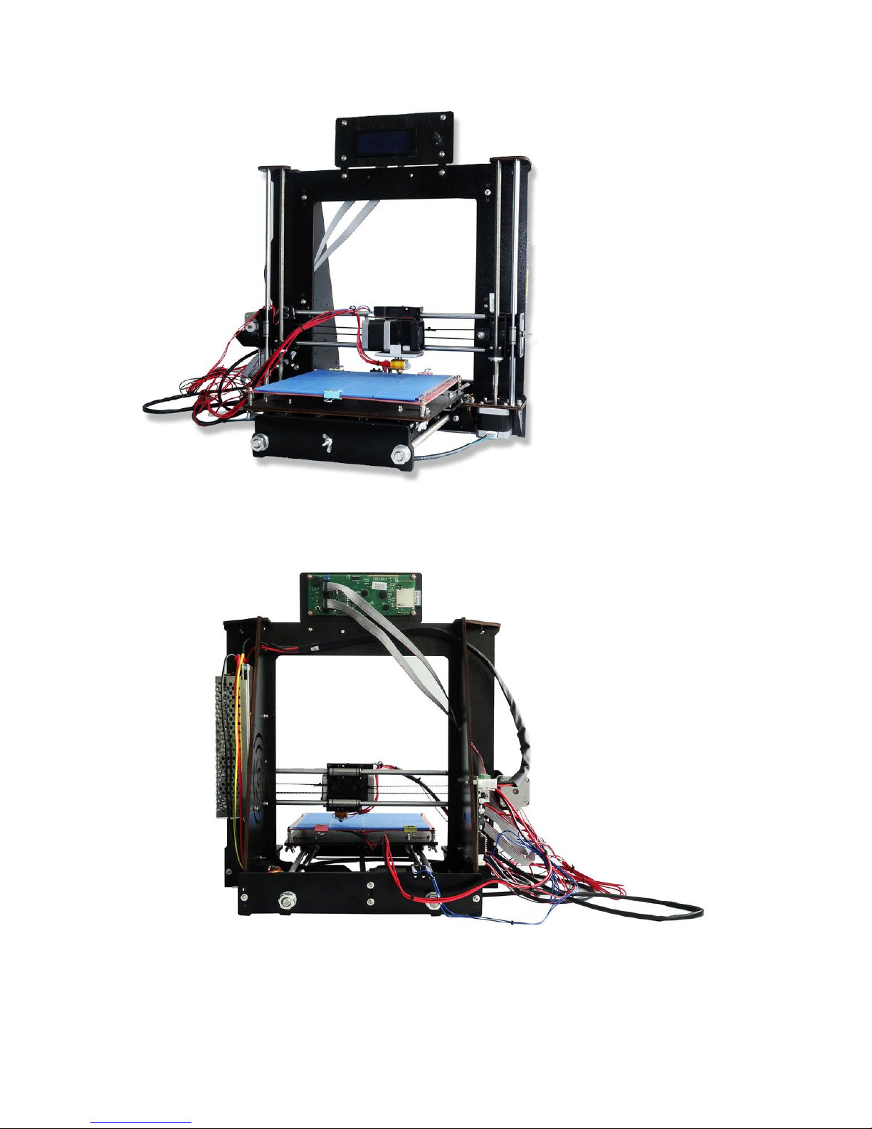
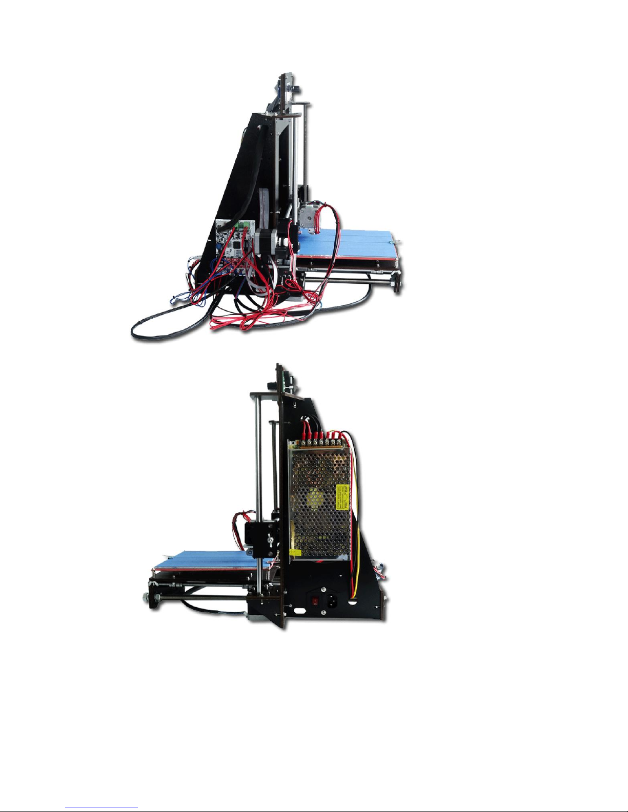
The major effect of main structure is shown in Figure 9 and Figure 10. The cable
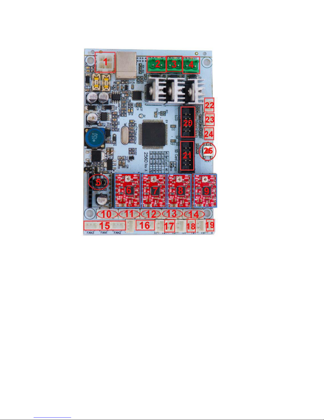
ports of motherboard and their functions are shown in Figure 11. In order to get
the right installation, it is suggested to see the finished product display pictures
to get general idea of the overall fitting effects and to identify the installation
directions and positions.
Page 7
7
Figure 9
Figure 10
Page 8
8
Figure 11
(1.power source of motherboard; 2. heating bed; 3. Left nozzle power (spare) ; 4.Right
nozzle power; 5. Left nozzle driver(spare); 6. Right nozzle driver ;7.Z shaft driver; 8. Y
shaft driver; 9.X shaft driver; 10.motor power of Left nozzle(spare); 11. motor power
of Right nozzle; 12. motor power of Z shaft; 13. motor power of Y shaft; 14. motor
power of X shaft; 15. Cooling fan of nozzle; 16.Cooling fan of Power source; 17. Z
shaft stopper; 18. Y shaft stopper; 19. X shaft stopper; 20. LED port. 21.SD card
ports;22.temperature sensor socket of Right nozzle; 23.temperature sensor socket of
Left nozzle 24.temperature sensor of heating bed(spare); 25.function reset key of
motherboard )
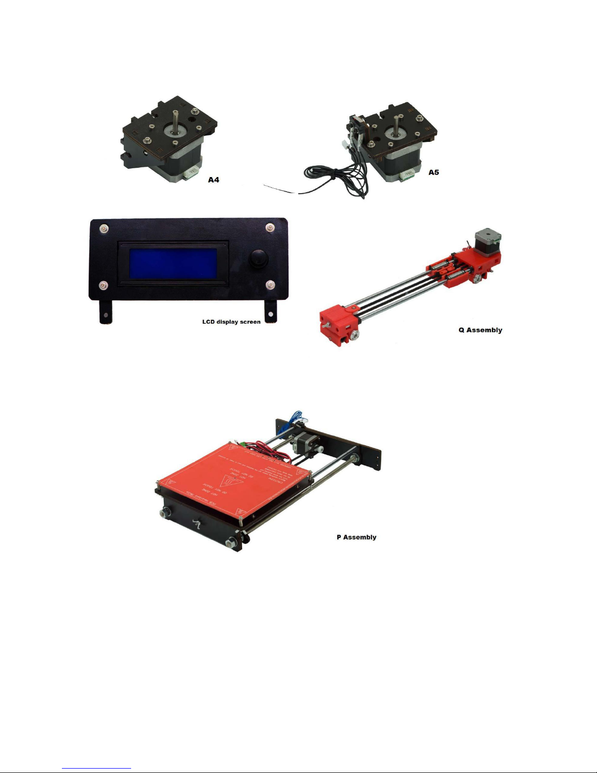
1. Collect all assemblies before installation: A4, A5, Display screen, Q & P
assembly as shown in the following Figures:
Page 9
9
2. Find out
○
21
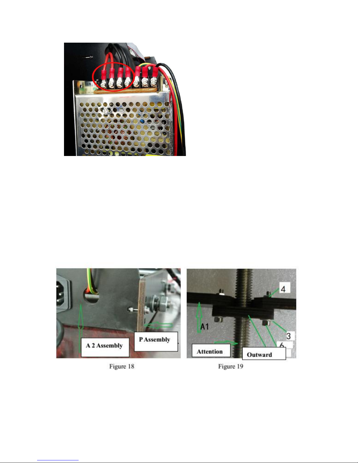
Dupont cable, use it to connect the motherboard on A2 and the
power supply on A3. One end of the power cable connection is shown in Figure as
below and the other end is connected to port 1 on the motherboard.
Page 10
10
3. 3.Installation of P assembly - Printing bed
Accessories:
○
6
M3 x 16mm screws x6 ;
○
4
nut x6 ;
○
22
Power cable x 5 (3 short +2
long)
Align the holes of P assembly with the holes of previous installed main structure.
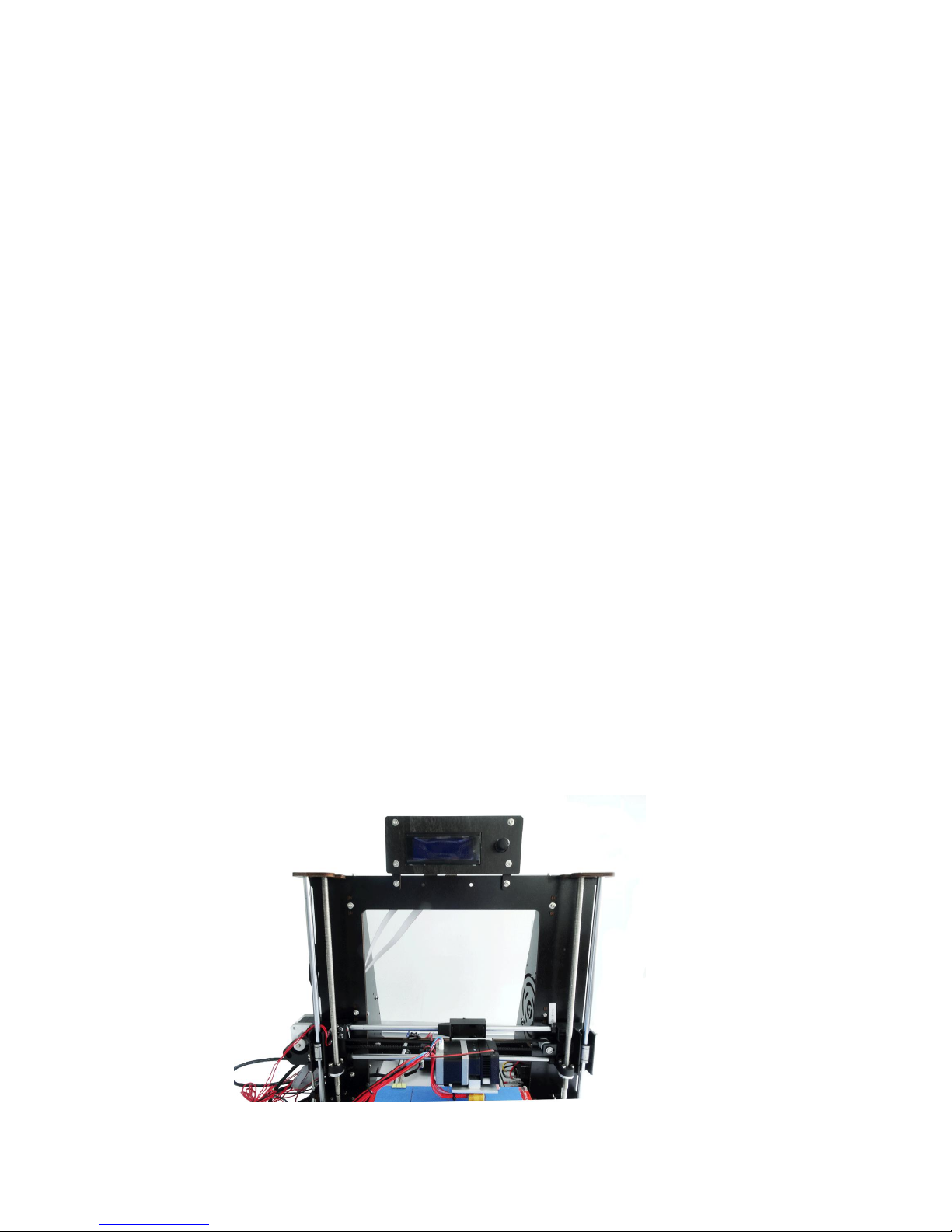
Then fix the two and install P assembly to the main structure as shown in figure 18.
Then follow figure 19 to install the bottom of P assembly to the A1 assembly.
4. Installation of
○
31
A4 assembly
Accessories:
○
6
M3 x 16mm screws x3 ;
○
4
nut x3 ;
○
3
M3 Washer x3
Align the holes of A4 assembly to the A1 frame, fix it to the left bottom of the A1
Page 11
11
assembly. Then connect the motor to port 15 on motherboard with short
○
22
Power
cables, and connect the limit stopper cable to port 16 on motherboard.
5. Installation of
○
32
A5 assembly
Accessories:
○
6
M3 x 16mm screws x3 ;
○
4
nut x3 ;
○
3
M3 Washer x3
Align the holes of A5 assembly to the A1 frame and install A5 assembly to the
right bottom of the A1 assembly. Then connect the motor to port 11 on
motherboard with the long
○
22
Power cables.
6. Installation of display screen
Accessories:
○
6
M3 x 16mm screws x2;
○
4
nut x2 ;
○
3
M3 Washer x2 ;
○
13
display
screen cable
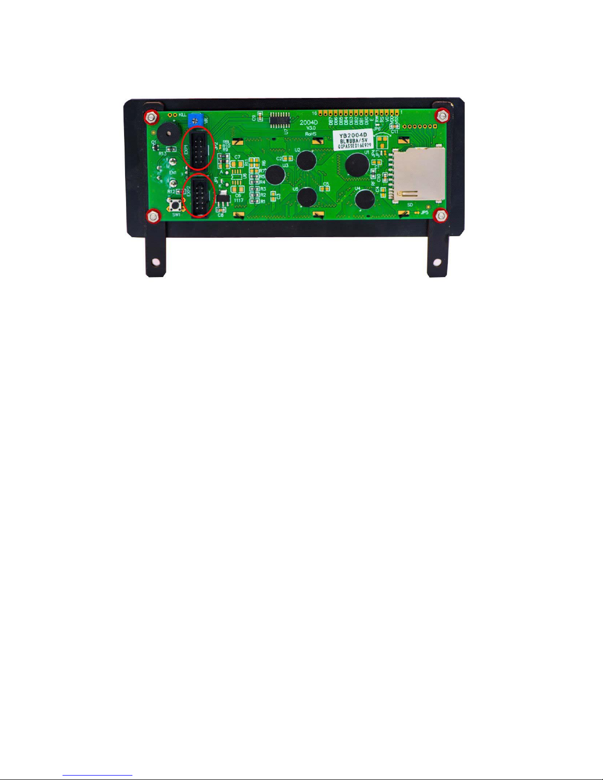
Align the holes of the display screen and A1 assembly to fix the two together. The
LED display screen is outward as shown in Figure below. Connect the display
screen to port 19 on the motherboard with
○
13
display screen cable. Port 19 on
motherboard connect to EXP1 port on display screen, port 20 on motherboard
connect to EXP2 port on display screen.
Page 12
12
7. Installation of Q assembly
Note: Because each size of assembly may bear some deviation on production, in
order to obtain good installation and functions, it is suggested to pay attention to
the installation of the Q assembly. If necessary, please adjust the right side of Q
assembly to left or to right to ensure the normal functions, and adjust the length
of the belt according to actual gap.
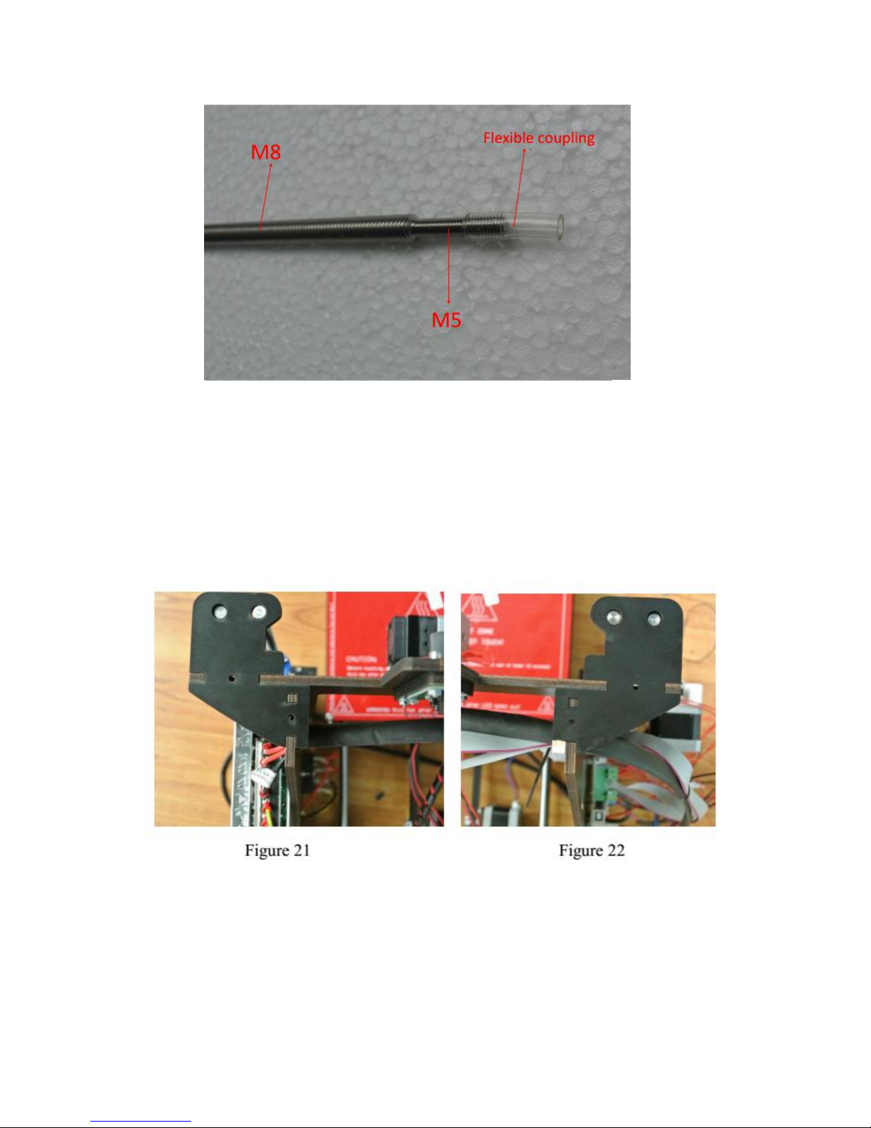
Before assembly, the first Z-axis screw M5 ends connect flexible coupling 30, is
prohibited after blowing hot and then install the flexible coupling to the M5
terminal end of the flexible coupling insert M5 depth of about 10mm. As shown
below:
Page 13
13
(1) Accessories:
○
38
Z top mount x 2;
○
6
M3 x 16mm screws x4;
○
4
nut x4 ;
○
3
M3
Washer x4
Align holes of the Z top mount with A1\A2 assemblies and with A1\A3 assemblies,
fix them with screws as Figure shown below:
(2) Accessories:
○
1
S
mooth rod x2;
○
8
Screw locking ring x2
Get the guide rods
○
1
go through the hole of
○
38
Z top mount,
○
8
Screw locking
ring and the outside bearing of the P assembly from up to down in both sides.
Page 14
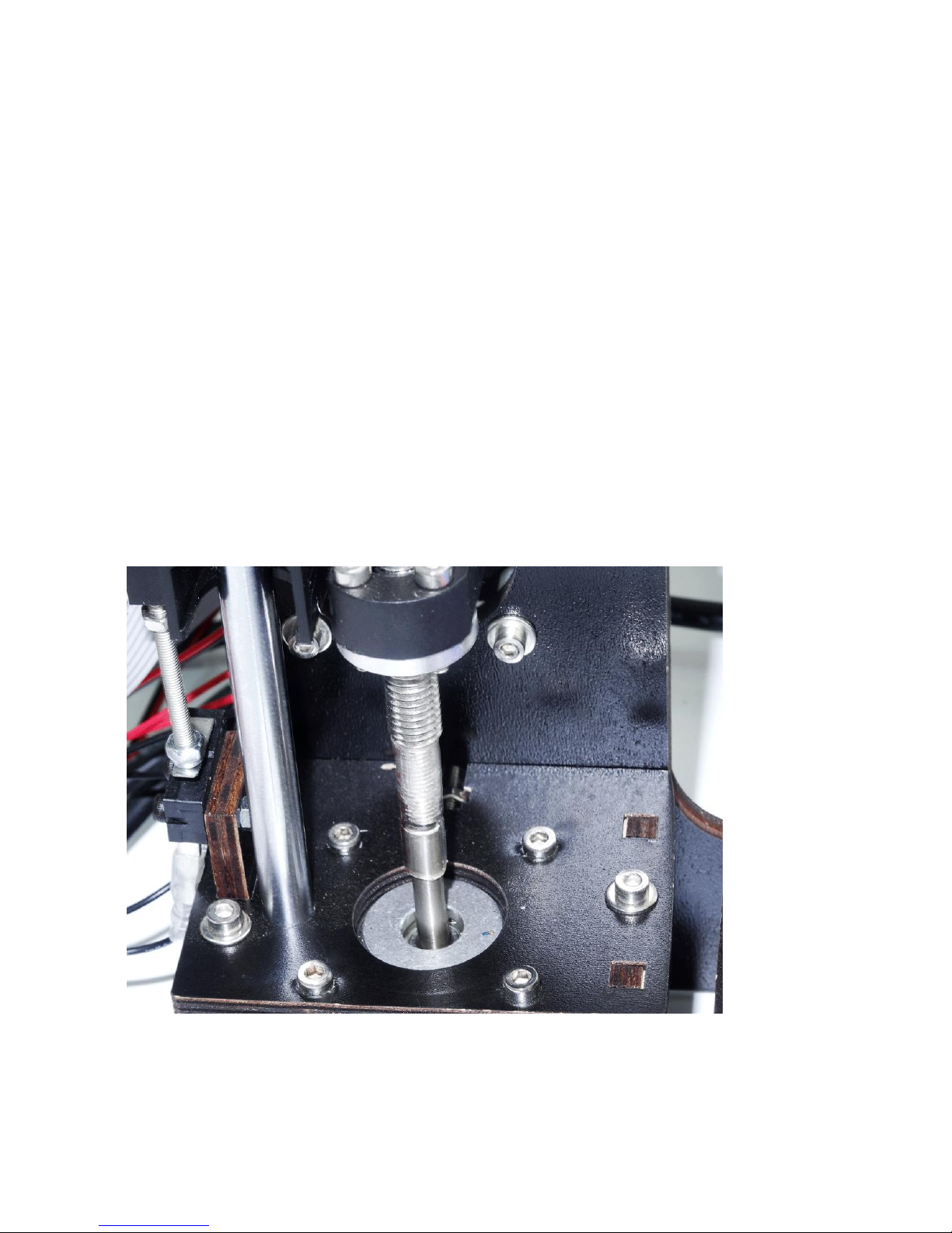
14
Adjust the distance between left and right side of P assembly, move
○
8
Screw
locking ring to the joint of guide rod
○
1
and
○
38
Z top mount and fix it.
(3) Accessories:
○
2
Threaded rod x2
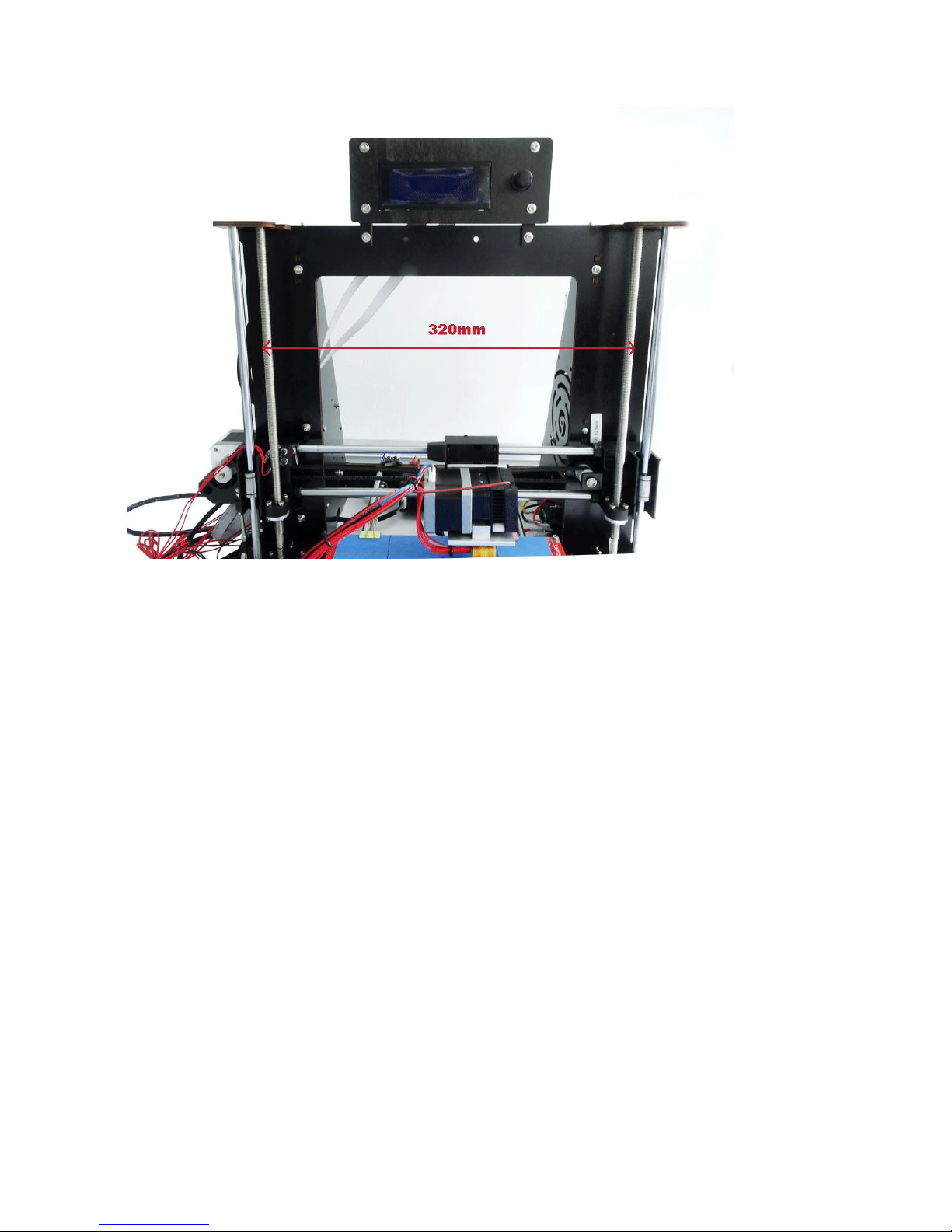
Get the
○
2
Threaded rod go through the hole of
○
38
Z top mount from up to down in
both sides, rotating into the internal hole of P assembly, and insert to the shaft
couplings above the motors of A4 assembly and A5 assembly. Adjust the distance
between the two sides of P assembly to ensure the correct installation. Adjust the
horizontal distance between the outer ends of the two
○
2
Threaded rods as
320mm. Secure the tightening screws of shaft coupling on the upside of the
motors.
Page 15
15
(4) Connect the Stopper cable (red) of Q assembly to port 18 on motherboard.
8. Installation of Nozzle
Accessories:
○
6
M3 x 16mm screws x2;
○
4
nut x2 ;
○
3
M3 Washer x2
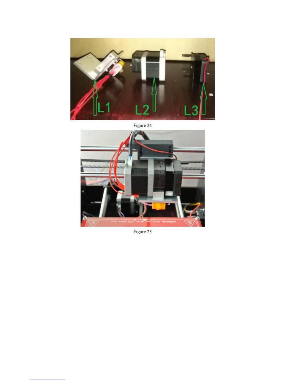
First unscrew the cooling fan on the nozzle, dismantle the nozzle to L1,L2, L3 as
three parts. Install L1 part to the movable part of P assembly with
○
6
M3 x 16mm
screws,
○
4
nut and
○
3
M3 Washer. Please note that get
○
6
screw go through L1
first and then through the movable part of P assembly. Then install the nozzle and
fan in the reverse steps as it was dismantled. Connect motor of the nozzle to port
10 on the motherboard with long power cable
○
22
, and connect the fan cable to
port 14 on motherboard. Connect power cable of nozzle to port 3 on motherboard.
Connect temperature sensor of nozzle to port 21 on motherboard.
Page 16
16
Debugging and Notes
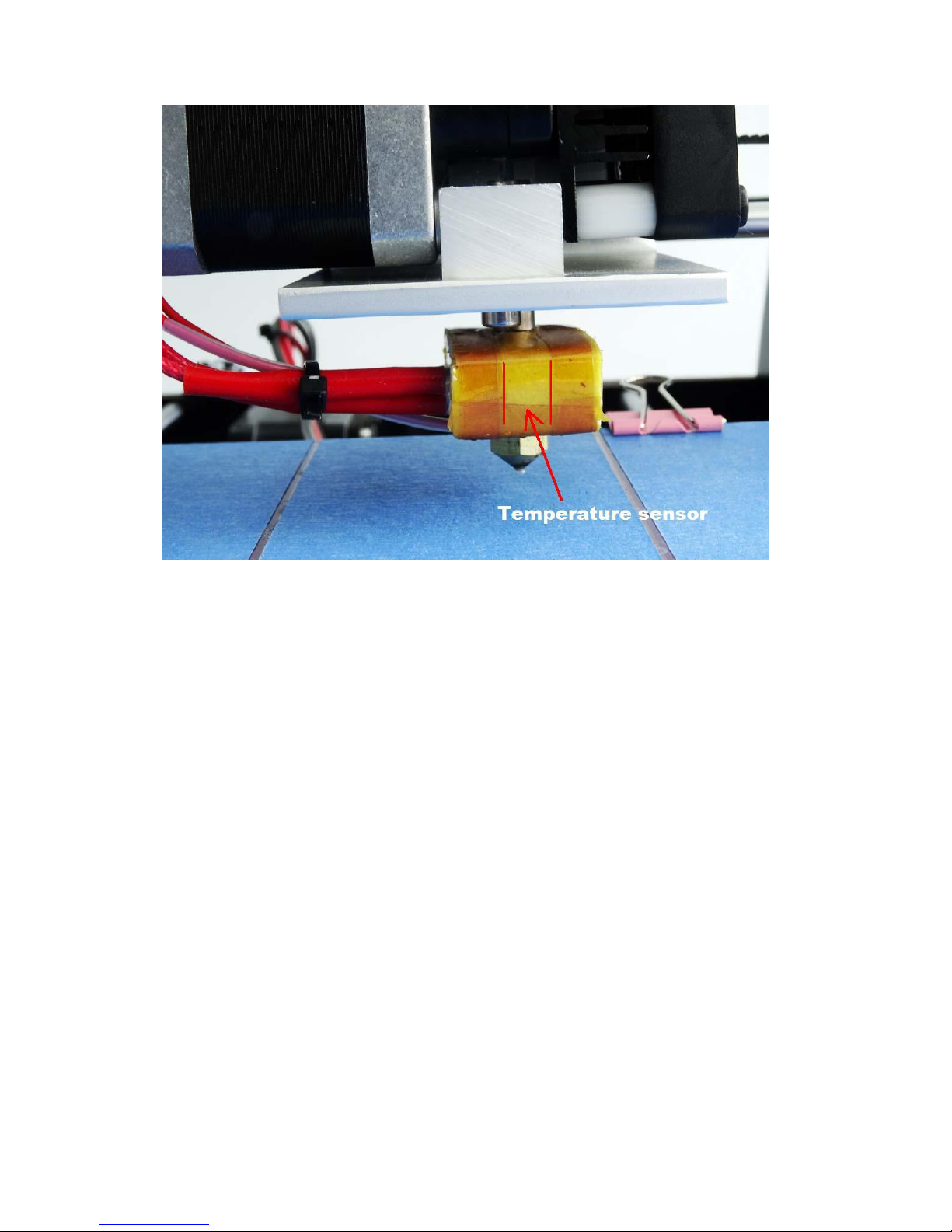
1. Make sure the temperature sensor cable of the nozzle is in the correct position,
as shown in Figure as below:
Page 17
17
2. Make sure the connection of cables are in normal state. Then debug if position
function of the limit stopper is normal, in particular pay attention to the
debugging of Z-axis’ limit stopper. Click Function Key to choose Prepare, then
choose Auto home and click confirm to check each stopper. Adjust the nut of the
long screw on the left of Q assembly, adjust the lowest position of Z-axis moves
down to ensure the gap between the nozzle and the printing bed.
3. Cut off the power and put the square glass with masking tape on top of the red
heating bed, fix it with the 4 Dovetail clamps, please note the position of the
dovetail clamps should not affect the functions of the nozzle and among others.
Move the nozzle to check if the printing bed is parallel with the nozzle, and keep a
proper gap. Then power on, check the original position of the nozzle and the gap
between nozzle and the printing bed, make sure there is proper gap.
Page 18

18
4.Check if the threaded rod of the Z-axis is deformed, make sure the gap between
axis couplings of motors of A4 & A5 assemblies and the bed is 3mm.Try to keep
the shaft line of Z-axis threaded rod and the output shaft of motor in the same
straight line. Keep the horizontal distance of the upper and bottom sides of Z-axis
threaded rod is equal. Adjust these distance and gaps until no noise occur when
motor is moving on working.
5. The bundling of cables should not affect the moving space and functions of
each parts. Adjust the heating temperature of the printing head according to
practical conditions.
6.The sounds of rotational motors and cooling fans are normal.
7.Heating tube damage(Suitable for all FDM 3D printers): When stop using the
printer or need to clean the nozzle, use spanner to clamp the square aluminum
block and unscrewing the nozzle. Make sure the square aluminum block can not
move when unscrewing the nozzle, otherwise the heating tube would be damage.
8. Adjustment of belt: Cut the black nylon tie, readjust the size of the belt, fix it,
then secure it with nylon tie.
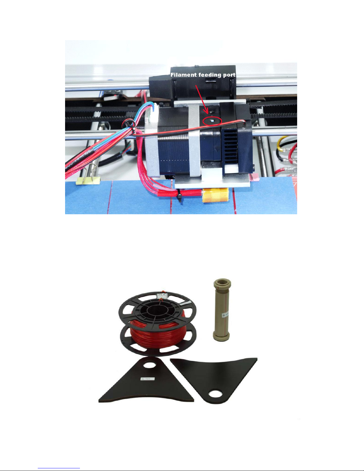
9. Filament feeding port is the outside one, refer to Figure as below:
Page 19
19
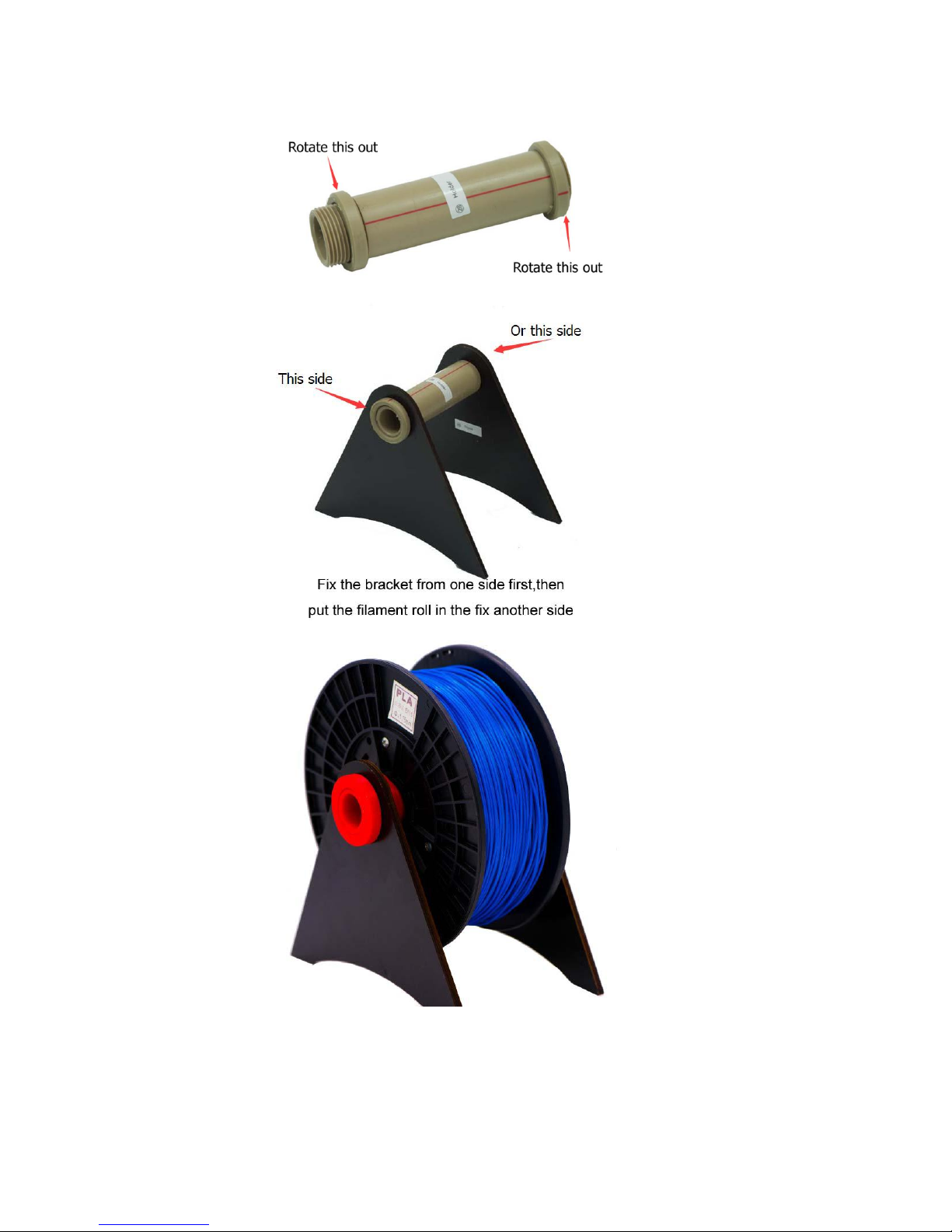
10. Spool holder with filament installation
Page 20
20
Page 21
21
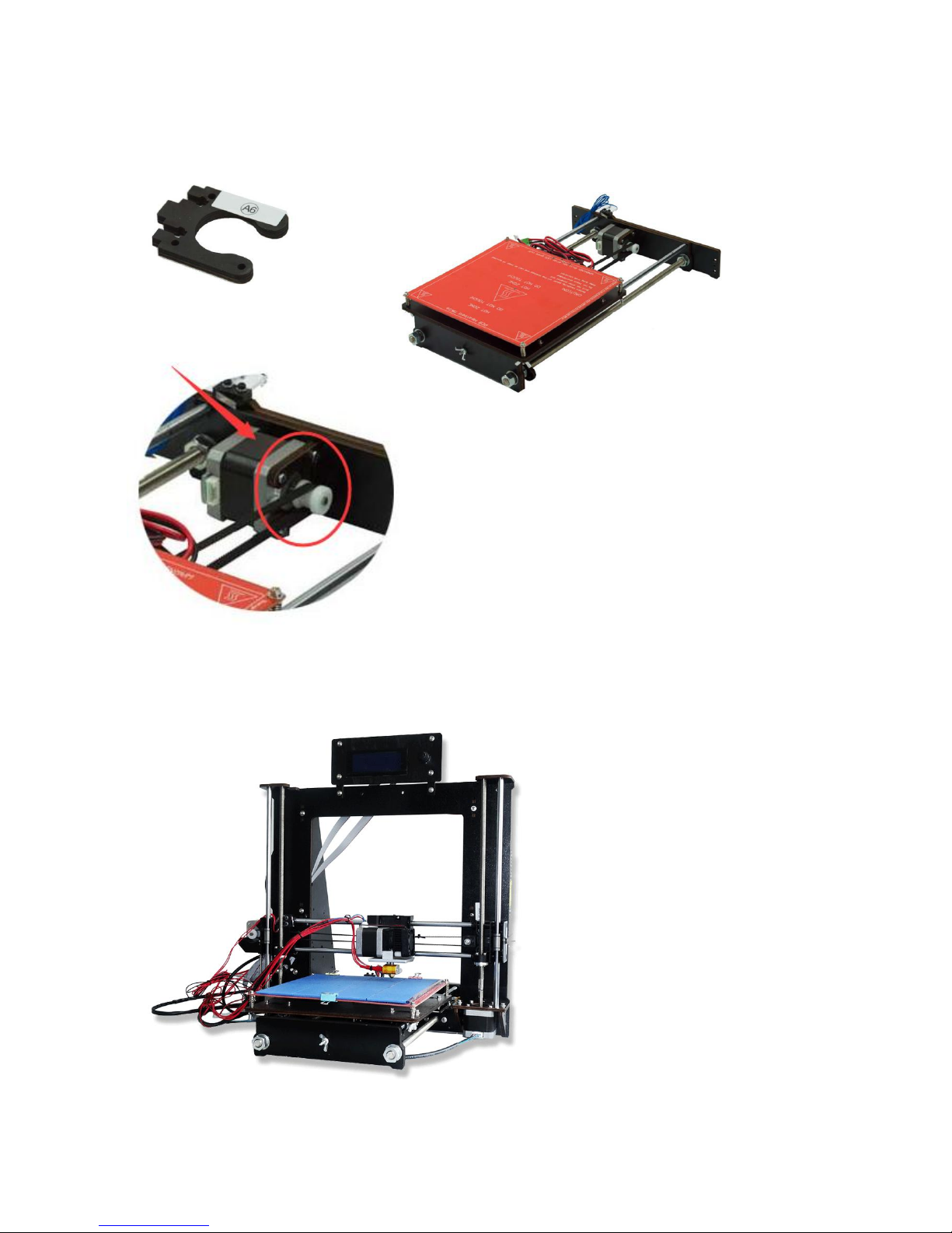
11. Y-axis motor fixing (back-up accessory)
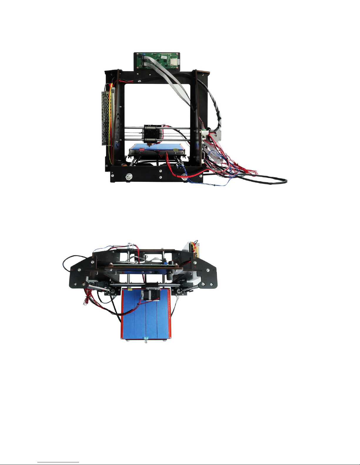
Finish Product Display :
Page 22
22
Page 23
23
Page 24

24
Product Parameters
1. Propose Environment
Operation Environment: Good ventilation. No dust
Temperature: 15°C~35°C
Relative humidity: 20%~80%(no condensation)
Storage Environment:
Temperature:0°C~40°C
Relative humidity: 10%~80% (no condensation. Free of corrosive gas and
clean)
2. Printer Parameters
Structure size: 200mmx200mmx180mm(these are the maximum size.
It is advised to decrease practical size)
Input voltage: 110V -220V
Applicable operation system: Windows 7/8(32bit/64bit)
Software: Cura
Printing raw material: PLA
Raw material property: Special PLA designed for 3D printing (exclusive
composition)
Layer precision: 0.1mm~0.5mm
Positioning precision: X/Y axis, 0.011mm; Z-axis,0.025mm
Filament diameter: 1.75mm
Nozzle diameter:0.4mm
Page 25

25
Moving axis speed: 30mm/s~100mm/s
Recommended nozzle moving speed: 35~40mm/s
Input file type: stl
Cooling method: wind cooling
Maximum temperature of nozzle: 260°C (usually 210°C)
Maintenance
1. Cleaning nozzle
The printing head have to be cleaned after the printer is used for a period of time.
Dismantle the printing head, remove the fan and the step motor, as well as the
black block at the feeding port on the motor, you will see the extruding gear of the
nozzle, clean the material in the extruding gear will be ok, then install these parts
back to the printer.
2. Tightening belt.
Notes: (1). Belt should be seamlessly contacted with the belt wheel.
(2). Forces of the two sides of the Y-axis wheel belt should be the same
(3). X-axis shall be perpendicular to Y-axis
3. Maintenance of axis and threaded rods
Oil the bearing steel of X,Y,Z axis with high quality lubricant. The oil amount is not
supposed to be too much. Just a little to lubricate the surface will be good.
4. Trouble shooting
4.1 Offset: If offset remains after screw tightening, please check if the belt wheel is
Page 26

26
on the same parallel line.
4.2 Abnormal temperature display 0-1024. Check if the thermocouple is correctly
connected. If so, change the thermocouple.
4.3 Temperature display is N/A. Check if the thermocouple is correctly connected.
If so, change the thermocouple.
4.4. X-axis moves abnormally with vibration. The X-axis motor cable should be
changed.
4.5 LCD screen turns blue without information or sudden rebooting after printer is
started or the Stopper switch of motor does not stop. Check if the sensor is
connected correctly. If so, then change the sensor cable.
4.6 Cooling fan does not work. First check if the fan can rotate when temperature
is over 40°C. If not, use screwdriver to check the ports connection or test it by
battery. If still not work, replace a new fan.
4.7 Motor does not rotate, change the motor driver board.
Common Problems and Solutions
1.Shifted layers
(A).Screws are firmed but still shift
a.Check the pulleys make sure they are parallel
b.Check if belts are loose, tighten them
B).Check drive on the mother board. Exchange drive boards of X Y Z for testing
C).Check elements such as bearing on the Q module,make sure they are firm
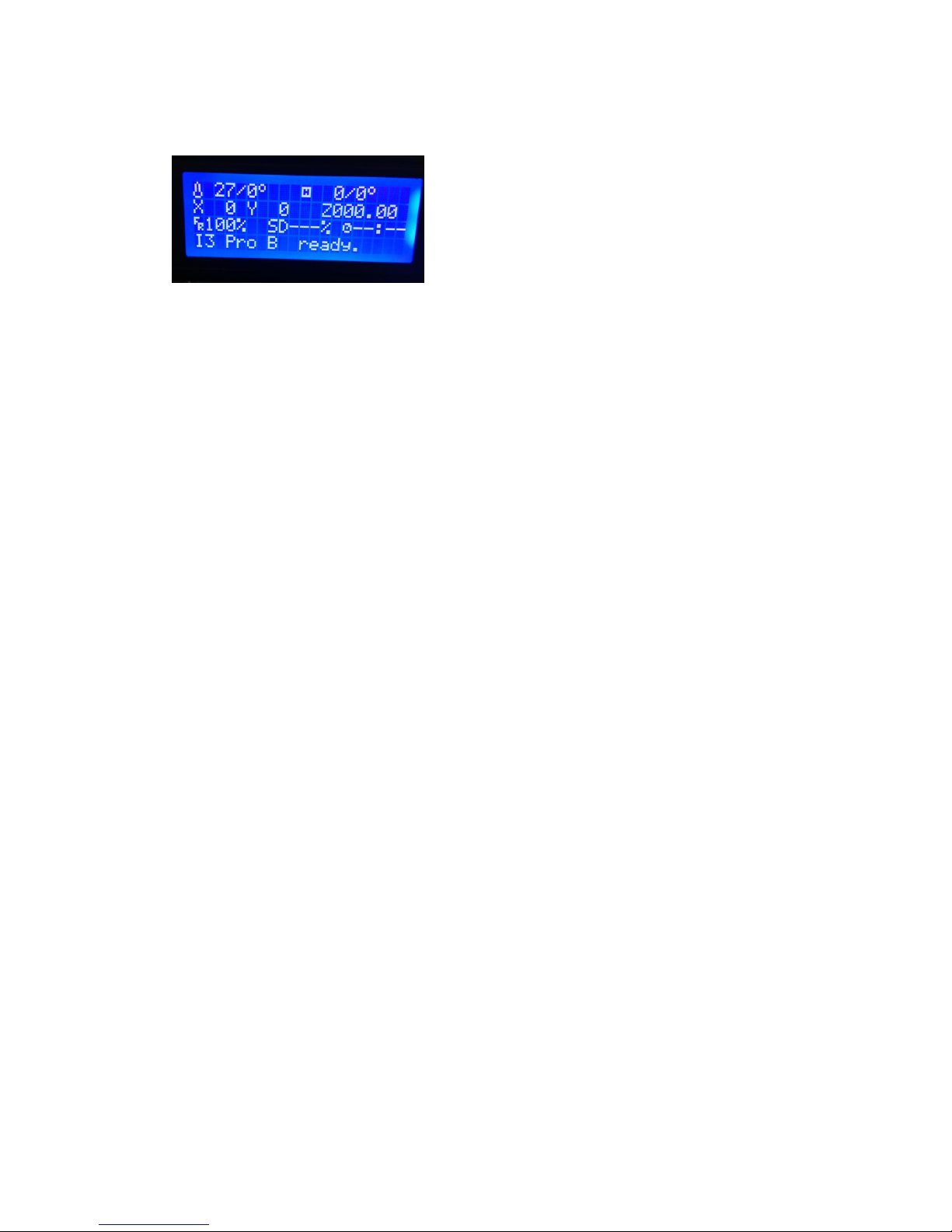
2. Screen shown as below means temperature sensor or temperature wire is not
Page 27
27
connected well
27°is temperature of nozzle, 0°is setting temperature for nozzle
0° is temperature of platform, 0°is setting temperature of platform
Check if connection of the wires of platform or mother board is connected well. If
both temperature 0°are not changed, it means temperature is not setting yet or
mother board broken.
3.X-axis moves abnormally or shaking
(a). Check the bearing of the belts and see if they are damage or deformation
(b). Check wires of the X-axis motor, if any problem change the wires
4. a.The LCD screen on but without display
b.The machine restart suddenly after switch on
c.The motor can not stop after touch the limit switch
Check connection of the sensor’s wires, if connection is no problem, there will be
problem of the wires, change the wires.
5.The fan is not working.
Make sure the temperature is above 50°C, if fan is not rotated,check the interface
and reconnect it. Or test by battery, if still not rotated, change the fan.
The default rotating speed of the fan is 255, if is 0,please adjust it to 255.
6. Motors can not rotate, check connection wires of the motors, exchange the
Page 28

28
wires for testing, if motor rotating, change the wire, if not ,change drive board of
the motor.
7.Filament is blocked:
a).filament is too thick
b).dismantle the nozzle.
8.Sliding: filament is too thin,cut part of filament
9. Nozzle is blocked: heating tube is blocked by filaments, dismantle heating part
and heat it to 220℃, then get filaments out with tweezers.
10. Abnormal temperature: thermocouple is damaged,change the thermocouple
11.Printing offset: Screw is loosened, check and tighten screw
12. Sample edge deformations: bed is too high, adjust the bed height
13. Filament is glued onto nozzle: supporting material are pulled by nozzle,reset
the parameters
14. Filament does not flow out: model is faulted,transform the model into code
and set parameters after model being corrected.
15.Driver or software cannot be installed: wrong system configuration, re-install
the system
16. print samples cannot be glued on platform: too large gap between nozzle and
bed,readjust the bed
17.Click any mode when printer is powered, the motor does not move,change a
new printer identifier.
18.Tape cannot be moved off: heat the platform to 20℃ or 30℃ and take off the
Page 29

29
tape completely.
19.When finish printing or need to change filament during printing. Please choose
the function of discharge, do not pull out the filament by force,the way will deform
the filament which is hot in the heating tube,thus will jam or damage the extrusion
gear.
20.The wood fix Y-axis is easy fracture, if it is broken, request for A13 wood for
replacement.
21.Z-axis can not move up and down or move very slowly, please operate Z-axis
in controlling setting. Otherwise exchange the motor wires or drive board of the
motors for testing.
22.Platform glass damaged. Do not press the platform glass heavily. After finish
printing, use the blade to prize up the model carefully and take it down. Do not
pull it up directly, this way will damage the platform glass easily.
For the model which wasn’t taken down on time. As after finish printing, the
printer will be cooling down, temperature of the platform will turn down to normal,
thus the model will be stick on the platform and hardly to take down, in this
situation, heating the platform up to 100°C, then it can be taken down easily.
23.LCD screen is not on.
(a). Check and confirm if connection wires of the screen and mother board are
connected correctly.
(b). Check if the white switch on the blue controller on the back of the screen is
loose, firm it with screw and see if the screen is on.
Page 30

30
24.The threaded rod bend, replace it.
25.Printer can not connect to computer: The computer without COM interface
drive will not be able to be connected.
26.Filament break off or stop extrusion:
Check if plastic extrusion gear is loose or damage, or the nozzles and heating tube
are jam, or filament tray is stuck.
Warranty statement and permit agreement
1. Quality guarantee
Each product you bought is attached with the promise given by CTC. We ensure
that each product manufactured by us is of high quality through strict accessory
fabrication standards and assembling inspection flows.
2. After-sale guarantee
(1) We promise to change or repair the product with quality problem within 3 days
after your receipt of the product (free of charge and we will bear the two-way
transport fees)
(2) We promise to change or repair the product with quality problem within 7 days
after your receipt of the product(free of charge and we will bear half of the two way
transport fees)
(3) We promise to change or repair the product with quality problem within 15
days after you receipt of the product free of charge. And you should bear the
two-way transport fees.
Page 31
31
(4) We offer free of charge consultation service to you about any product problem
after 15days since you have received the product. However, you should bear all the
cost for any accessory change and the two-way transport fees.
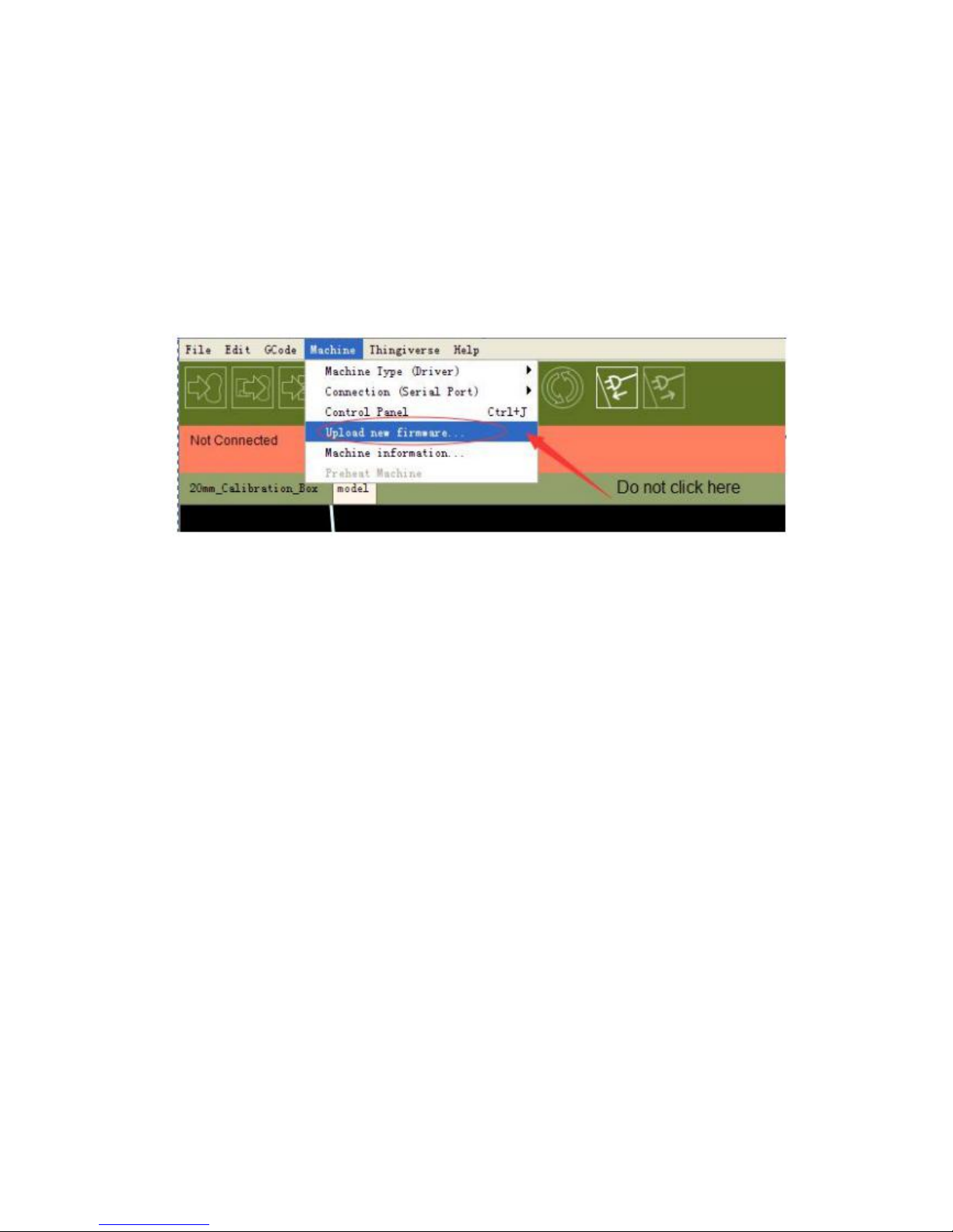
(5) Do not upgrade the firmware(as Figure shown below). Any damage caused by
upgrading the firmware is not within the warranty policy.
3. Notice for return or change
(1) Customer should carefully check if all the parts are included in the package
according to bill of materials as soon as you receive the printer
(2) CTC will not liable to any part damage caused if you have not complied with
the installation instructions. And you should bear all the cost of any part needed
to be changed and the transport fee.
(3) Because DIY printer will be installed by customer, the printing quality varies
from one customer to another. We will not accept any return request once the
printer is completely installed.
(3.1) Basic conditions for return/change: All the accessories, instruction manual
and outer package of the product should be the same as it was sold to you. We will
not accept return or change request if any one of the aforesaid is missed. You can
keep the free-of-charge articles for product change; You should send the
Page 32

32
free-of-charge articles to use with the product for product return.
(3.2)Return /change due to quality problem. Please carefully check the
completeness of product as soon as you have received the product. If any quality
problem is found, please take a photo and contact us within 5 days.
(3.3) Please note the following terms, otherwise, we will not offer return/change
service to you. (1) Any product that you request to change/return shall have all the
complete outer package, accessories and instruction manual, etc. (2)We will not
accept return/change if the product has been stained or damaged by personal acts.
(3) free-of-charge articles are not eligible for return/change. (4)No
return/change is accepted if you have used non-CTC consumables. (5)Product
that has been invoiced are not to be returned. You can change the product with
quality problem.
4. About Product Care:(1) After you finish printing, try to clean all the residual
consumables inside the nozzle to prevent nozzle being blocked next time. This is
also the rudimentary maintenance for 3D printer. Note: We will not offer repair
warranty if nozzle is blocked by consumables provided by other suppliers. (2) You
can add some anti-lubricant to guide track once a month. (3) During printing, do
not cut off the power directly or touch the conductive parts of printer with metal.
 Loading...