

Page 1
SERVICE INSTRUCTIONS
CALIBRATION
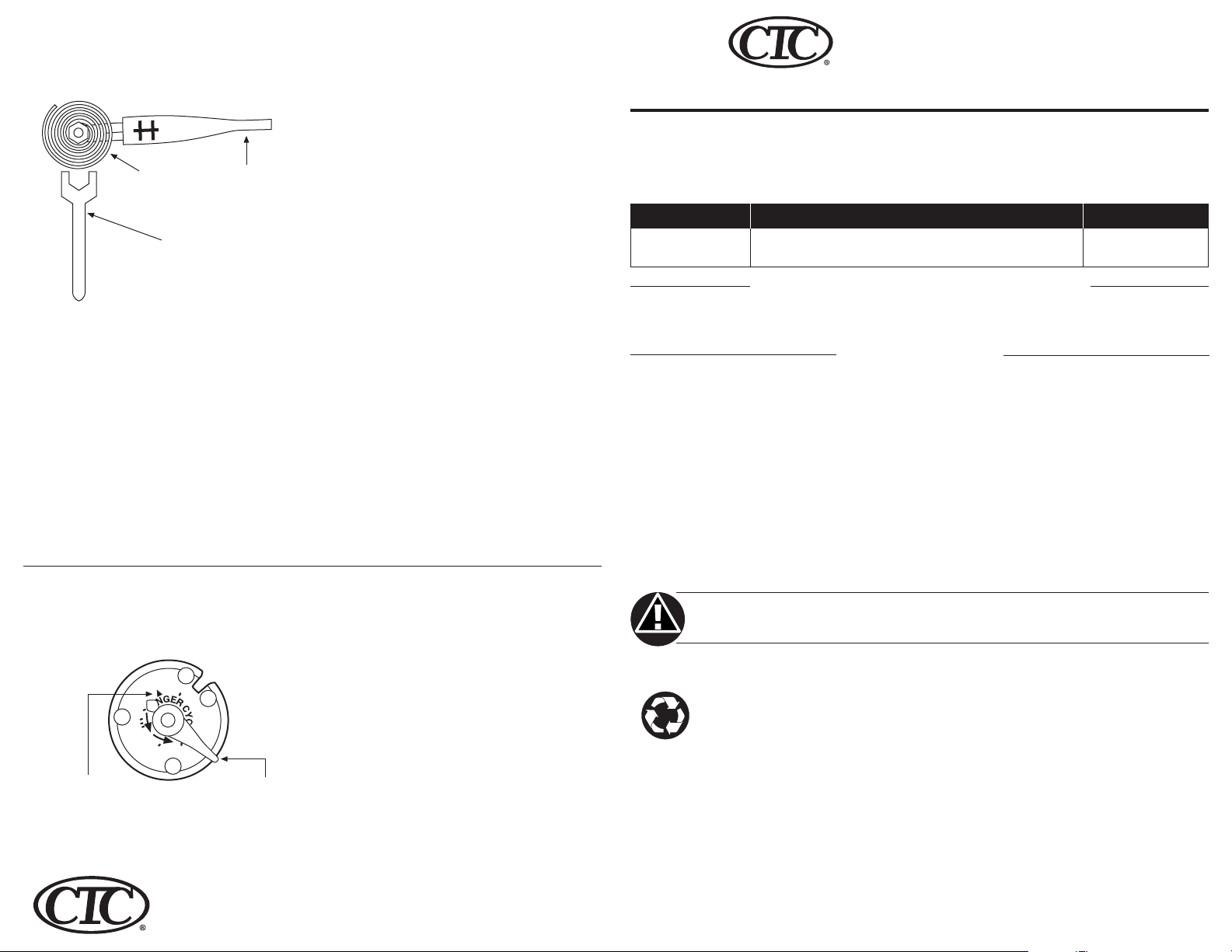
FIGURE 4 CALIBRATING THERMOSTAT
Bimetal
7/32” Calibration wrench
The thermostat is accurately calibrated
before leaving the factory and no further
calibration should be necessary. If the
thermostat appears to be out of calibration or for any reason fails to function
properly, a qualified serviceperson should
proceed as follows:
1. The anticipator’s heat may adversely
affect thermostat recalibration. To
prevent this, disconnect electrical
power, power to the thermostat at the
furnace, main fuse, or breaker box.
2. Move temperature adjustment lever to
a setting about 5˚ above room temperature.
FIGURE 5 ANTICIPATOR ADJUSTMENT
.4
.6
.8
.12
.2
Arrow points to the
matched current rating
of the primary control.
Temperature
adjustment
lever
HEAT ANTICIPATION ADJUSTMENT
.3
.25
Move this lever
to adjust heat
anticipator.
Climate Technology Corp.
2500 Frisco Avenue
Memphis, TN 38114
A Hunter Fan Company
3. Remove thermostat cover. Slip 7/32”
wrench onto hex nut beneath bimetal.
While holding temperature adjustment lever stationary, turn hex nut
clockwise until mercury shifts to the
right end of the tube for Heating
models. Left end of tube for Cooling
models.
4. Move temperature adjustment lever to
lowest setting.
5. Replace thermostat cover. Wait 10
minutes for bimetal temperature to
stabilize. Do not stand near the
thermostat during this period, as your
breath and body heat will affect
bimetal temperature.
6. Move temperature adjustment lever to
correspond to actual room temperature. Then remove thermostat cover.
7. Slip 7/32” wrench onto hex nut. While
holding temperature adjustment lever
stationary, turn hex nut counterclockwise until mercury just barely
shifts to the left end of the tube for
Heating models. Right end of tube for
Cooling models.
8. Replace thermostat cover and set
temperature adjustment lever to
desired temperature. Turn on electrical
power to system.
Some heating installations require longer
or shorter “ON”, “OFF” periods to
maintain even temperatures. For average
conditions, set the heat anticipator
indicator to match the current rating of
the primary heating control. Move
indicator approximately 1/2 division in
direction indicated by the arrows on the
thermostat for longer “ON” cycles, or
move lever in opposite direction for
shorter “ON” cycles. Allow at least 24
hours to determine if setting provides
satisfactory operation before making any
further adjustments.
NOTE: Cooling anticipation is fixed, and
cannot be adjusted.
41660-01 9/9/03
MERCURY BULB
MECHANICAL
CLIMATE
TECHNOLOGY
CORPORATION
CTC thermostats regulate 24 to 30 VAC single-stage heating-cooling systems. See the
chart below for specific models and applications.
THERMOSTAT MODELS AND APPLICATIONS
PART NUMBER APPLICATION ORIENTATION
43309 Use in standard 2-wire heating systems Horizontal
43320 Use in standard 2-wire cooling systems Vertical
TOOLS NEEDED FOR INSTALLATION
• Slotted Screwdriver • Electric Drill and 3/16” Bit
• Hammer • Level
SPECIFICATIONS
ELECTRICAL DATA
Switch Rating: 24 VAC (30 VAC max.)
Heating Models – 0.2 to 1.2 amps
Cooling Models– 0-1.5 amps
Switch Action: Sealed mercury switch
Anticipator Rating:
Heating Models – Adjustable from 0.2
to 1.2 amps
Cooling Models – Fixed 24 VAC
THERMAL DATA
Temperature Range: 50˚F – 90˚F (10˚C – 32˚C)
WARNING!
To avoid electrical shock or equipment damage,
make sure power is disconnected before installation.
DISPOSAL INFORMATION
This product contains mercury
in a sealed tube. DO NOT place
this control in the trash at the
end of its useful life.
If this product is replacing a control that
contains mercury, DO NOT place the old
product in the trash.
Contact your local waste management
authority for instructions regarding
recycling and the proper disposal of this
product, or of and for any old control
containing mercury in a sealed tube.
THERMOSTAT
APPLICATIONS
This thermostat is designed for use with:
• Standard heating or cooling systems
• Electric heating systems
• Millivolt systems
This thermostat cannot be used with:
•Two-transformer systems
• Multi-stage applications
INSTALLATION
When installing this product:
• Read these instructions thoroughly.
Failure to follow them could damage
the product or produce an unsafe
condition.
• Check the ratings in these instructions
and on the product to make sure the
product is compatible with your
application.
• Installation must be performed by a
trained, experienced service technician.
• Upon completion of the installation,
verify the correct operation of the
product as detailed in these instructions.
Page 2
LOCATION
The thermostat should be located in an
area with good air circulation at average
temperature. It should be on an inside
wall.
DO NOT place the thermostat where it
can be affected by:
• Drafts or dead spots behind doors or in
corners.
• Hot or cold air from ducts.
• Radiant heat from the sun, fireplaces,
or appliances.
• Unheated (uncooled) areas behind the
thermostat, such as outside walls.
This thermostat is a precision instrument
and was carefully adjusted at the factory.
Handle it carefully.
ATTACH THERMOSTAT
TO WALL
Disconnect the power supply before
beginning installation to prevent electric
shock or equipment damage.
All wiring must comply with local codes
and ordinances.
This thermostat includes a wallplate and
can be mounted with or without it.
Mount Wallplate and Thermostat
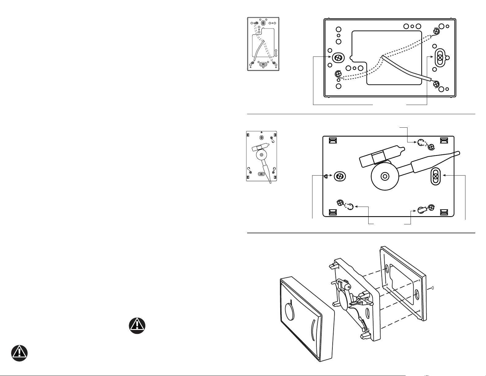
• Pull wires through large opening in the
wallplate
• Connect wires as shown in Figure 1,
R and W for Heating models
R and Y for Cooling models
• Push excess wiring into wall and plug
hole with fire-resistant material (such as
fiberglass insulation) to prevent drafts
from affecting thermostat operation.
• Position wallplate over hole in wall and
mark mounting locations. Use any
existing mounting holes if possible.
• If the mounting screws will be going
into drywall only, then drill 3/16”
mounting holes for use with the
included plastic anchors.
• Fasten wallplate loosely to wall with
two mounting screws. Place a level on
the top wallplate, adjust until level,
then tighten the mounting screws.
An incorrectly leveled thermostat
will cause the temperature
control to deviate from the
setpoint.
• Remove cover from thermostat base by
gripping the base in one hand. Use the
other hand to pull gently at the top or
bottom of the cover.
• Carefully remove the protective
packing.
• Attach thermostat base to wallplate,
being sure that 3 captive screws are
tightened snugly, since they serve as
electrical connections between thermostat and wallplate (refer to Figure 3).
• Snap cover on thermostat and set
temperature lever to desired setpoint.
•Turn on power to the system.
Mount Thermostat Only
• Remove cover from thermostat base by
gripping the base in one hand. Use the
other hand to pull gently at the top or
bottom of the cover.
• Carefully remove the protective
packing.
• Push excess wiring into wall and plug
hole with fire-resistant material (such as
fiberglass insulation) to prevent drafts
from affecting thermostat operation.
• Position thermostat over hole in wall
and mark mounting locations. Use any
existing mounting holes if possible.
• If the mounting screws will be going
into drywall only, then drill 3/16”
mounting holes for use with the
included plastic anchors.
• Pull wires through the holes next to
each terminal on the thermostat base.
• Connect wires as shown in Figure 2,
R and W for Heating models
R and Y for Cooling models
• Fasten thermostat loosely to wall with
two mounting screws. Place a level on
the top of the thermostat, adjust until
level, then tighten the mounting
screws.
• Snap cover on thermostat and set
temperature lever to desired setpoint.
•Turn on power to the system.
An incorrectly leveled thermostat
will cause the temperature
control to deviate from the
setpoint.
FIGURE 1 WALLPLATE MOUNTING
Y
R
Rotate 90 degrees
for vertical models
FIGURE 2 THERMOSTAT MOUNTING
W
Rotate 90 degrees
for vertical models
FIGURE 3 ATTACH THERMOSTAT TO WALLPLATE
W
Y
Y
R
Y
Mounting screw
Cover
Mounting screws
Wire opening
Wire openings
Thermostat
W
R
W
R
Mounting screw
Wallplate
 Loading...