

Page 1
Climatic - Treatment of the Air
ZA du caillou, 3 rue Jules Verne, 69630 CHAPONOST, FRANCE
Phone: +33 (0)4 78.56.70.70 Fax: +33 (0)4 78.56.17.31
Instruction Manual
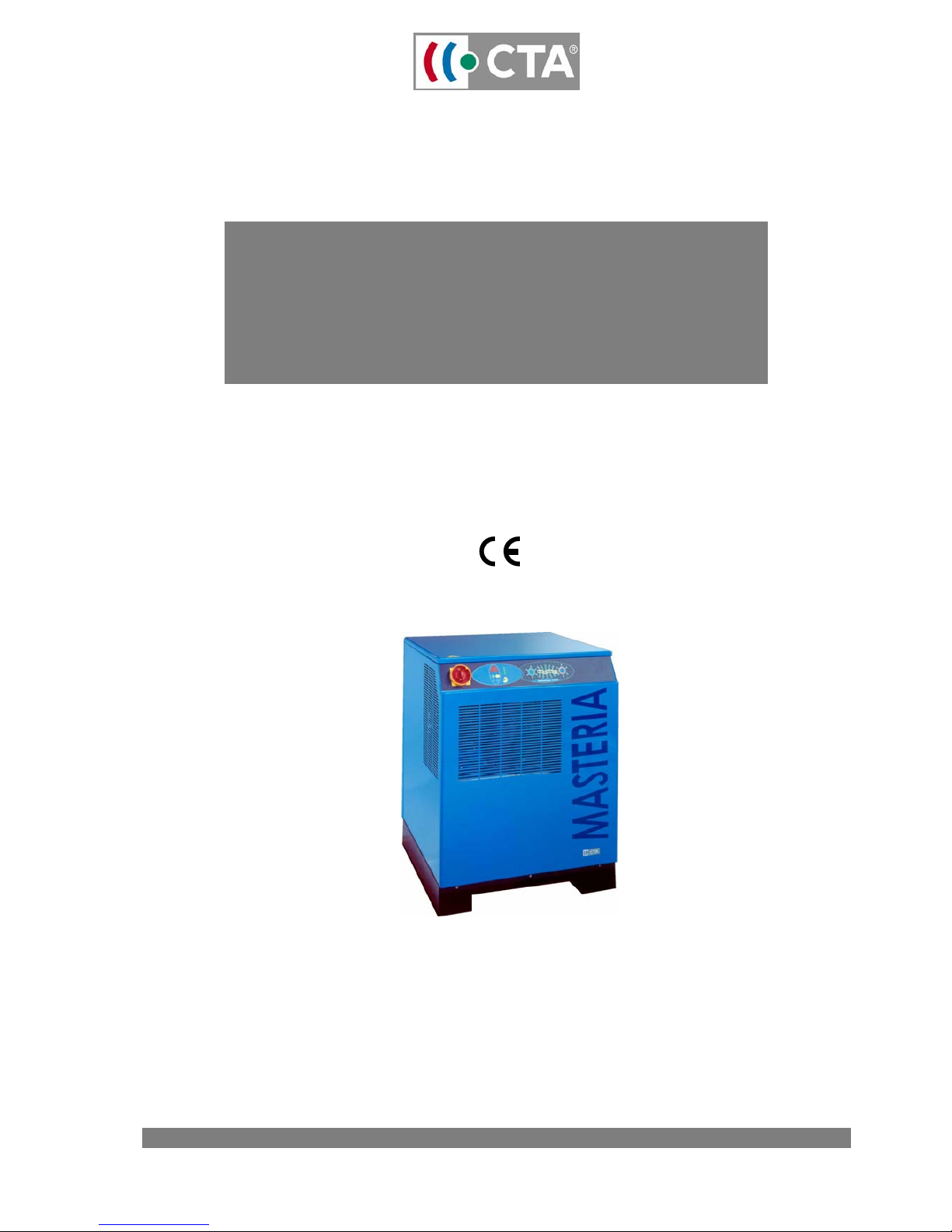
MASTERIA
compressed air dryer
INSTALLATION, USE, MAINTENANCE
Models
MPE 006 to MPE 150
Page 2

CTA Instruction Manual MPE
Reference: MT0027DA This document may be modified without prior notice 2
Revision date: 11/05/06 Even partial reproduction is prohibited without authorisation in writing
Contents
1 Introduction 3
1.1 Principle 3
1.2 Originality 3
1.3 Standards 3
2 Safety 4
2.1 General precautions 4
2.2 Cooling fluid safety notice 5
3 Installation 6
3.1 Inspection 6
3.2 Handling 6
3.3 Layout 6
3.4 Electric connection 7
4 Use 8
4.1 First start up 8
4.2 Normal Start up 8
5 Programming 9
5.1 User interface 9
5.2 Changing set points 9
5.3 Changing purging duration 10
5.4 Purge test 10
5.5 Choice temperature unit 11
6 Maintenance preparation 11
6.1 Shut down and close all circuits 11
6.2 Access inside the drier 11
6.3 Closing 11
6.4 Start-up and return to the network 12
7 Maintenance operation 12
7.1 Cleaning the purge filter* 12
7.2 Solenoid valve maintenance * 13
8 Test and maintenance scheduling 13
9 Alarm 14
10 Components interns arrangement 14
11 Troubleshooting 15
12 Design specifications 17
13 Appendices 18
13.1 Use of a purge with a level detection function 18
14 Circuit diagrams 19
14.1 Refrigeration/pneumatic circuit diagram (SC0014A) 19
14.2
Wiring diagrams (SE00148, SE0015, SE0018, SE0017 and SE0018) 20
Page 3

CTA Instruction Manual MPE
Reference: MT0027DA This document may be modified without prior notice 3
Revision date: 11/05/06 Even partial reproduction is prohibited without authorisation in writing
READ THIS MANUAL ATTENTIVELY
BEFORE INSTALLING OR USING THE APPLIANCE
These symbols inform you about dangers and the measures to be taken to avoid them.
The comments in bold type emphasise the key points to observe to ensure you use your drier correctly.
1 Introduction
1.1 Principle
Your Mastéria drier dries air by refrigeration. Hot, wet compressed air entering the Mastéria drier is cooled by
an exchanger down to the programmed dew point temperature. The steam which condenses in liquid form
during cooling is separated mechanically and is then purged by an electronic system with a time-out.
The compressed air leaving the appli ance is dry.
1.2 Originality
Your Mastéria drier has several unique features compared with the other products on the market:
• Reduced consumption due to an ai r-to-air heat exchanger in all models i n the range above the MPE010.
The dry, cold air from the drier is used to pre-cool the hot, wet air inlet.
• Mechanical separation guaranteed i n all operatin g modes by a condensate separator developed from 10
years experience.
• High quality, anti-corrosion construction that is easy to maintain and very strong.
• Electronic regul ation with a user-friendly, clear, digital display panel.
Finally, and especially,
• DTM
®
technology, providing a host of additional benefits
• Robustness: DTM
®
technology eliminates fragile, pressure-operated val ves
• Economy: DTM
®
technology only uses minimum power
• Safety: DTM
®
technology guarantees the total integri ty of the compressed air circuit from any risk of
contamination by the cooling agent. This ensures that ai r quality meets the highest standards.
• Performance: DTM
®
technology guarantees you get exactly the dew point you set.
1.3 Standards
The air delivered by Mastéria dryers complies with ISO standards 85 731 and 7183.
Mastéria range dryers comply with the following European directives:
• 89/336: " Electromagnetic Compatibility "
• 89/392/EEC: " Machine Safety "
• 73/23/EEC: " Low Voltage"
• 97/23/EEC : "Pressure Equipment"
!
Page 4

CTA Instruction Manual MPE
Reference: MT0027DA This document may be modified without prior notice 4
Revision date: 11/05/06 Even partial reproduction is prohibited without authorisation in writing
2 Safety
Everyone involved in installing, using and servicing Mastéria dryers is concerned by this manual and must
have read and understood the instructions given below.
Danger of electric shock and burns: every badly connected or misused electrical appliance is
dangerous. For your personal safety and that of all the people who will approach this appliance,
rigorously follow all the security instructions given in this manual. All interventions on the refrigeration
circuit must be carried out by specialists. Every leak or anomaly must be pointed out to qualified
people immediately.
2.1 General precautions
Compressed gases which can be dried
Your Mastéria drier is designed to dry compressed
air. You must obtain prior authorisation from the
manufacturer in writing before drying any other
gas.
Precautions to take before drying compressed air
Ensure that the free parts of the components
designed to expel the compressed air are blocked
sufficiently to prevent whipping shocks caused by
stiffening when the compressed air flows through
them.
Precautions during installation
The installation must be carried out by qualified
personnel reporting to a qualified supervisor.
The power supply to the drier must be protected by
thermal fuses or relays as shown in this manual.
All the electric connections m ust be complyi ng with
local regulations. The drier and its auxiliaries must
be earthed and protected from short-circuits and
overloads.
When the master switch is closed, the electric
voltage reaches can kill. Consequently, take ev ery
precaution when working on the electric circuit.
Do not open the electric circuit access panels with
the equipment switched ON unless necessary for
tests, measurements or adjustments. This task must
only be carried out by qualified personnel, using the
appropriate equipment and protected from the
inherent dangers.
For a single-phase power supply, fit a neutral
conductor earthed in the transformer station
(system TN as stipulated in IEC 364 - HD 384 - IEC 64-
8) or by the electric power utility (TT system).
In systems with several dryers, install manual v alves
so each machine can be isolated separately.
Fit a safety valve to each tank or appliance
containing air at a pressure higher than
atmospheric pressure. Fit a safety valve between
the compressor and the first by-pass valve.
If raised access platforms are installed around the
drier, take care that they do not impede use or
access for lifting or dismantling components.
Platforms and steps must be made from gratings or
tiled, and be equipped with safety handrails on all
open sides.
Precautions during operation
Dryers must only be operated by qualified
personnel reporting to a qualified supervisor.
If the temperature of pipework or any other parts
which could be touched accidentally by the
personnel during normal operation could exceed
60C° (140°F), they must be protected and insulated.
All air pipes must be pai nted or clearly marked as
stipulated in local safety regulations.
Do not remove or touch the safety devices,
protection or insulation fitted to the drier or its
auxiliaries.
Precautions for maintenance and repairs
Dryer maintenance, revision and repair must be
carried out by qualified personnel reporting to a
qualified supervisor.
When scrapping equipment, it must not pollute
conduits or rivers. Do not burn materials which
could pollute the air. Only use storage methods
which respect the environment.
Only use original spare parts supplied by the
equipment manufacturer.
Keep a log of all the interventions carried out on
the drier and its auxiliari es. The frequency and the
nature of the work completed during a given
period can reveal abnormal operating conditions
which require correction.
Only use the cooling gas specifi ed on the machine
plate.
Check that all instructions rel ating to operation and
maintenance are respected and that the drier, the
auxiliaries and all safety devices are serviceable.
Always keep the drier clean. During maintenance
work, protect the components and plug the
openings exposed with clean rags, for example.
Never weld or carry out work which releases heat in
the vicinity of a system containing oil. Before
carrying out such operations, all components which
contain oil must be emptied and washed with
steam, for example.
To prevent operating temperature and pressure
rises, check and clean all heat exchanger surfaces
regularly, (for example, the condensing unit fins).
Schedule cleaning for each drier.
Take care not to jam the safety valves or other
pressure limitation devices with paint, oil, dirt, etc.
!
Page 5

CTA Instruction Manual MPE
Reference: MT0027DA This document may be modified without prior notice 5
Revision date: 11/05/06 Even partial reproduction is prohibited without authorisation in writing
Take all appropriate precautions when welding or
carrying out any other repairs which release heat,
flames or sparks. Protect all components in the
vicinity with non-flammable material. Drain
lubrication system parts or components containi ng
oil if working close to them.
Never use a naked flame as a light to inspect the
drier.
Before dismantling a drier make sure that all the
moving and heavy parts are attached. After the
intervention, check that no tool rag or waste has
been left inside.
Check the direction of rotation of the electric
motors, and, in particular, the fan, when starting the
machine after an intervention on the electric
connections or the power supply cut-out.
All protection systems must be reset after repair or
maintenance.
Do not clean components with flammable liquids
when the drier is operating.
If non-flammable chlorinated hydrocarbons are
used for cleaning, take all safety precautions to
prevent injury from the toxic vapours released.
Before removing any panel or dismantli ng any part
of the unit:
1. Turn off the power supply to the drier by setti ng
the master switch to "OFF " and removing the fuses.
2. Stick a label on the lever of the master switch
and install a «WORK IN PROGRESS - DO NOT
ENERGISE " warning panel. Do not touch the master
switch and do not try to start the drier if the warning
panel is in place.
3. Close the by-pass valves up- and down-stream
from the drier and install on each valv e a “WORK IN
PROGRESS - DO NOT OPEN " warning panel. Only
reopen these valves when restarting the drier.
4. Check that all pressurised components in the
system have reverted to atmospheric pressure.
Check that all the pressure gauges indicate a
pressure of zero bars, i.e. atmospheric pressure.
2.2 Cooling fluid safety notice
Mastéria dryers use a cooling gas of the type
shown on the manufacturer's plate on the
appliance.
Very dirty refrigerating circuits, for example
following a compressor fire, must only be cleaned
by a qualified refrigeration technician. Comply
with current safety laws and regulations.
The refrigerant is not flammabl e, explosive, toxic or
corrosive in normal conditi ons. When released into
the atmosphere, it becomes a heavier-than-air
and almost odourless vapour. In contact with a
naked flame or a very hot metal surface, this
vapour breaks down into highly irritant products
which are immediately noticeable.
If the refrigerant gas leaks, it is adv isable to air the
buildings concerned abundantly and to shut down
all the systems likely to break down the vapours by
flame or heat immediately.
Every intervention on the cooling circuit must be
carried out by qualified personnel approved by
CTA.
In the event of:
• chilblains, warm up the frozen skin as soon as
possible.
• splashes in the eyes, rinse abundantly with
running water.
Then consult a doctor immediately.
Page 6
CTA Instruction Manual MPE
Reference: MT0027DA This document may be modified without prior notice 6
Revision date: 11/05/06 Even partial reproduction is prohibited without authorisation in writing
3 Installation
The installation procedures described in this chapter must only be executed by qualified personnel.
The following procedure must be scrupulously respected or the safety of all staff could be at risk.
3.1 Inspection
Immediately after unpacking the drier, check that i t is undamaged. If necessary, make a damage claim to
the carrier who delivered the equipment.
Never install or use an appliance damaged during shipment.
3.2 Handling
If using hoists to lift the equi pment make sure they are safe. To prev ent acci dents, check that all chai ns, hooks,
rings, slings, etc., are in good condition and suitable for the load. They must be tested and approved as
stipulated in local safety regulati ons. Cables, chains and ropes should never be attached directly to the lift
lugs. Always use a correctly positioned ring or a hook. Lay out the lift so that hoisti ng cables do not form
excessively tight c u rves.
Use a bar to avoid side loads on hooks and lugs. Stand at a safe distance away from the load while it is bei ng
lifted. Ensure that lift accelerations and velocities are within safety limits and never leave a load suspended
longer than necessary.
3.3 Layout
Throughout installation, stop compressed air production of to avoid risks to installation personnel.
1. The dryer should be installed on a flat surface
suitable for the weight of the appliance in a
closed, dry, room which cannot freeze. Access
to the room must be restricted to qualified
maintenance and test personnel. The room
must be sufficiently ventil ated with clean air free
from flammable gases or solvents. The drier must
not be exposed directly to heat sources. The
temperature of the room must not exceed 43C°.
Minimum and maximum ambient temperatures are
specified on the manufacturer's plate on the
drier. Unless otherwise stated, dryers are
designed to function in ambient conditions at a
temperature of 25C°. Higher temperatures may
reduce the capacity of the drier and result in an
increase in the dew point. Usually this does not
cause a problem if the compressed air network is
also in higher ambient temperature condit ions.
2. Check that the drier is not surrounded by
equipment which does not comply with
European electromagnetic compatibility
directives as interference could deteriorate
appliance operation. Leave a minimum 1 m
space between the drier and all other electrical
appliances.
3. Leave adequate space around the drier for
maintenance. Position the drier to ensure that
cooling air cannot recirculate towards the
suction ports. Check that the drier does not suck
in hot air from the compressor cooling systems,
the final cooler or any other appliance.
Remark: The cooling air used by the dryer comes in by the rear
grid and comes out by the front grid
4. The position of the drier in the compressed air
distribution system depends on the way the
compressed air will be used (see installation
plan).
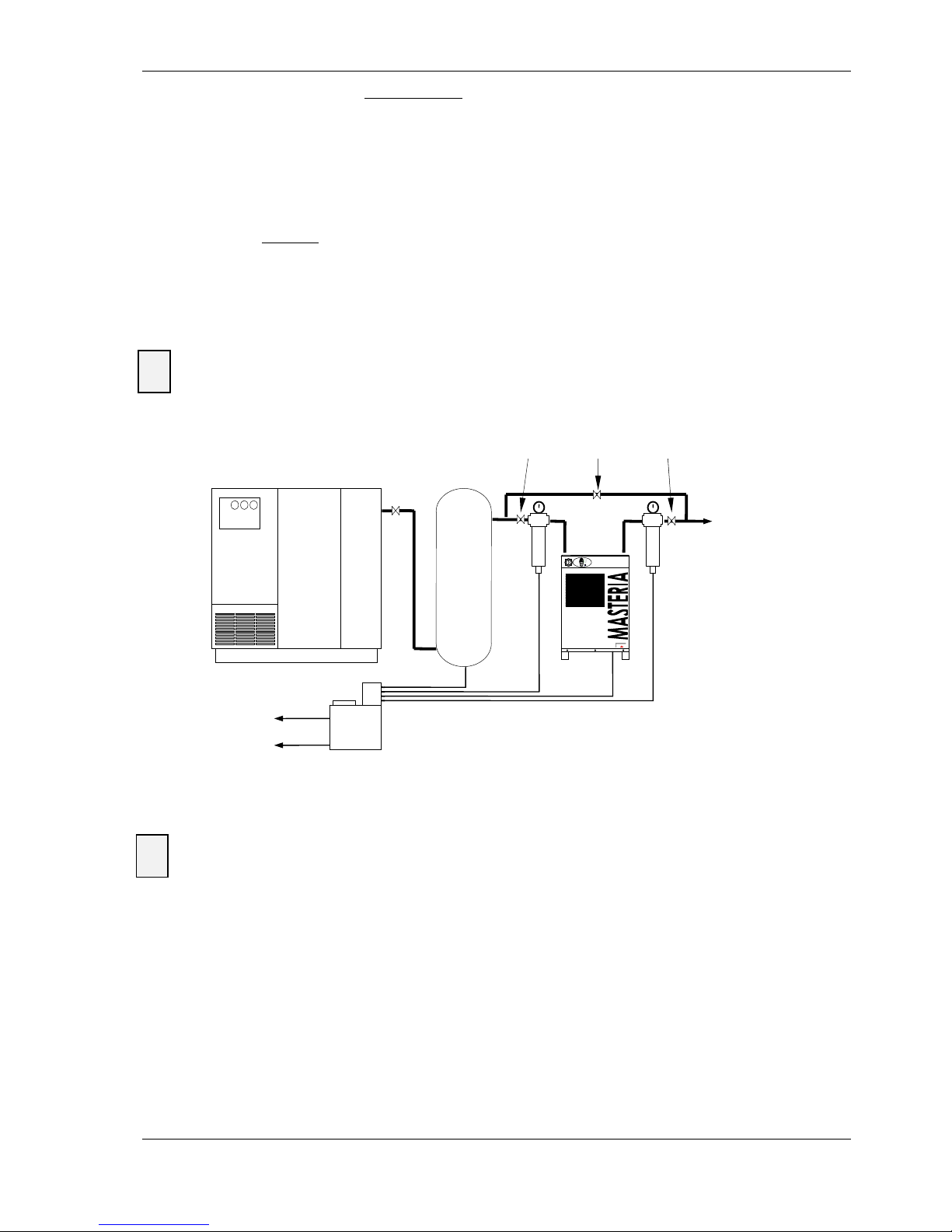
− The drier must be installed downstream from the tank if the
compressor pumps intermittently or if total demand for air
does not exceed the total compressor flow rate capacity (the
usual case).
− The drier should be installed upstream fr om the tank if th e tank
has been dimensioned to permit wide fluctuations in
compressed air demand or if peak demand exceeds
maximum compressor flow rate capacity.
5. Fit by-pass valves between the drier inlet and
exhaust so that maintenance can be carried
out without having to shut down the
compressed air supply to the network (see
diagram below). During installation, the
upstream and downstream valves must be
closed.
6. Additional fittings
- fit a class 4* type P solid pollutants filter (15m,
µ8mg/m3) upstream from the drier
- fit a class 1* type S total oil 1fi lter (0.01mg/m3)
downstream from the drier to remove dust and
oil from the compressed air. Only use filters
equipped with an automatic purge system.
!
! !
Page 7
CTA Instruction Manual MPE
Reference: MT0027DA This document may be modified without prior notice 7
Revision date: 11/05/06 Even partial reproduction is prohibited without authorisation in writing
7. Connect the compressed air to be treated to
the drier inlet (lower port) with pipes which do
not place stresses and strains on the appliance.
8. The compressed air to be treated must be taken
from the upper part of the tanks to reduce the
risk of transporting liquid phase water or
particles. This will extend the service life of the
appliance.
9. Connect the treated
compressed air to the
exhaust side of the drier with pipes which do not
place stresses and strains on the appliance.
10. If the compressed air production system is not
fitted with a safety device (valve or pressure
switch) you must fit a safety valve to each tank
They must act directly on the tank with no
intermediate position and possess a discharge
capacity higher than the quantity of air inlet to
the tanks, calibrated and sealed at the safety
pressure of your network which must always be
under 20 bars.
11. Check all connections for leaks.
12. Connect the drier and filter purge lines to your
condensate treatment system (water/oil
separation). Unless otherwise stipulated by
applicable legislation, do not drain wastes to
sewers without prior treatment.
* see ISO standard 8573-1
For air dryer inlet and outlet connexion's tightening, be sure not to use too much screwing tight power
which would damage the evaporator coil piping of the thermal mass.
Typical layout
3.4 Electric connection
Risk of electric shock: the circuit must be wired by a qualified electrician in compliance with applicable
legislation and the specifications of the appliances to be connected.
Check that voltage and frequency comply with the values shown on the manufacturer's plate on the
machine and that they are within the tolerances shown on the electrical ci rcuit diagram.
Check that the electrical install ation complies with laws and regulations current in the pl ace where the drier
will be installed. Only use the electric cable provided with the machine or equivalent.
At the entry of the electric cable, a safety device must be installed for:
• Protection from short-circuits and voltage surges;
• Protection from the indirect contacts on the machine (short-circuit between phase and equipotential
safety circuit) by automatically power supply cut-off as stipulated in IEC standard 364 - HD384 IEC 64-8;
• Protection from the fai lure of one phase in a three-phase electric installation.
For safety circuit dimensio ns, refer to the data shown in the electric diagram (maximum current, peak current,
cable cross-section).
!
!
P
S
Treated
compressed
Air
Water
Oil
Air compressor
Tank
Up-
stream
Filter
Down
stream
filter
By-pass
valve
Condensate
separator
Upstream
valve
Down
stream
valve
Page 8

CTA Instruction Manual MPE
Reference: MT0027DA This document may be modified without prior notice 8
Revision date: 11/05/06 Even partial reproduction is prohibited without authorisation in writing
4 Use
4.1 First start up
Only start up the drier once you have thoroughly tested all the hydraulic, refrigeration and electrical
connections.
1. Close the isolating valves on the drier and open the by-pass valve.
2. Check that the master switch is set to O.
3. Start the air compressor
4. Set the master switch to I. The drier digi tal di splay panel comes ON.
5. The refrigerating compressor and the fan start after a 2 minute safety time-out.
6. Pressurise the drier by slowly opening the inlet valve.
7. Slowly open the drier exhaust valve and then close the by-pass.
8. The drier will operate until the digital display panel indicates 00°C (32°F).
9. The drier will then stop for at least 2 minutes and will only start again when the digital display panel
indicates 04 °C (or 39°F).
If the compressed air flow oscillates, it is normal for these values to be exceeded temporarily.
10. Check that the purge opens when the TEST button is pressed.
11. Check that the solenoid valve opens automatically every 5 minutes.
The drier is now ready to run normally.
4.2 Normal Start up
The following key points will optimise daily use:
• Always turn your drier ON 5 to 10 m i nutes before the air compressor. I n this way, your compressed air will be
treated from the first m3.
• Your appli ance can remain ON even if compressed ai r production i s stopped. Its electronic regulati on will
automatically start and stop it to meet demand. You only need to turn off your drier at night, at the
weekend or when you go on holiday!
• The standard drier parameters programmed in our factory meet 90% of all appli cati ons. If the condi tions i n
your plant are standard (i.e. not a very hot environment, no partial drying upstream, no volu ntary increase
in the dew point...), do not spend time on modify ing these parameters.
!
Page 9
CTA Instruction Manual MPE
Reference: MT0027DA This document may be modified without prior notice 9
Revision date: 11/05/06 Even partial reproduction is prohibited without authorisation in writing
5 Programming
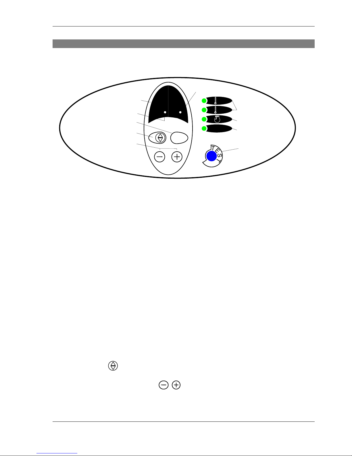
5.1 User interface
Digital display panel
• The digi tal di splay panel normall y i ndi cates a temperature in °C or °F dependi ng on the LEDs i ndi cati ng the
measurement unit selected.
• During programmi ng and as stipulated by the parameter sel ected, it indi cates the value of the parameter
in °C, °F or seconds.
• When the first digi t point is blinking, that means the sensor is in default (cut or short circuited). When the
second digit point is blinking, that means the sensor temperature measurement is out of the range the
electronic card can read.
Buttons
5 buttons are used to visualise and modify the various parameters of the Mastéria unit's electronic regulation.
LEDs
4 LEDs indicate the operating condition of the drier or the regulation.
5.2 Changing set points
General
The factory-programmed set point normally meets the nominal capaci ty of your drier and is also appropriate
for all the flows lower than nominal. A change of set point may be necessary to obtain a dew point higher
than the standard dew point to authorise flows higher than nominal capacity or in a particularly hot
environment.
Adjustment
• Press button for 15s.
The set point flashes on the digital display panel.
• Use the buttons to modify the set point
The adjustment range is from 0 to 10 °C (32 to 50F°)
• To record the new value, wait 5 seconds without pressing a key. The digi tal display panel reverts to its
normal status (i.e. stops flashing) and indicates the variation between the measured value and the set
point.
88
°C
°F
ζ
ζ
Digital display panel
Set point adjustment
Modification
Second digit point
First digit point
Purge adjustment
Purge test
Temperature unit
Compressor activity
Purge activity
Page 10

CTA Instruction Manual MPE
Reference: MT0027DA This document may be modified without prior notice 10
Revision date: 11/05/06 Even partial reproduction is prohibited without authorisation in writing
5.3 Changing purging duration
General Comments
Condensate purging automatically starts every 5 mi nutes for duration adjustable from 1 to 20 seconds. The
factory setting meets nominal drier operatio n conditions. However, you may have to:
• Increase the duration of purging if the temperature of the air to be treated is higher than nominal and if
you find liquid phase water downstream from the drier.
• Reduce
the duration of purging if the temperature of the air to be treated i s lower than nominal (case of a
water-type final cooling agent downstream from the air compressor) or if the compressed air to be treated
is not moisture-saturated (due to pre-drying or partial expansion)
Correct adjustment of the duration of purging is designed to limit compressed air leakage of to the bare
minimum necessary for this operation.
Correctly regulated purging:
• expels condensates (oil/water emulsion) during most of the purging sequence.
• releases a short blast of dry, condensate-free, compressed air at the end of the purging sequence.
Adjustment
• Press on button
for 15 seconds.
The purge duration value flashes on the digital display panel.
• Use the buttons to modify the purging duration value
The adjustment range is from 1 to 10 seconds.
• To record the new value, wait 5 seconds without pressing a key. The digi tal display panel reverts to its
normal status (i.e. stops flashing).
•
In case of extreme conditions of air drier working, it’s possible to adjust the closi ng time of the solenoid v alve.
Example, for adjusting the closing time 4 minutes (value adjusted in factory) to 2 minutes:
• Press on button
for 15 seconds.
The purge duration value flashes on the digital display panel.
• Use the buttons to modify the closing time to 2 minutes for example
• To record the new value, wait 5 seconds without pressing a key. The digi tal display panel reverts to its
normal status (i.e. stops flashing).
5.4 Purge test
General comments
Use the purging TEST button for:
• first start up
• routine testing,
• to depressurise the drier for m aintenance.
Procedure
1. Press the TEST button. Check that the solenoid v alve opens and those condensates run out. Check that
the Purge LED comes ON.
2. Press the TEST button. Check that the solenoid valve is closed and that condensate purging stops.
3. Wait 5 minutes and re-check that purging is carried out correctly.
4. If necessary, change the purge duration (see § 5.3).
Note: Each pressure on the TEST button opens or closes the solenoid purge valve. If you leave the solenoid purge valve
open, it will be closed automatically at the end of the pre-set purge duration time.
Page 11

CTA Instruction Manual MPE
Reference: MT0027DA This document may be modified without prior notice 11
Revision date: 11/05/06 Even partial reproduction is prohibited without authorisation in writing
5.5 Choice temperature unit
• Press both and buttons simultaneously for 15 seconds.
• Use the buttons to select the temperature unit shown on the LEDs.
• To record the new unit, wait 5 seconds without pressi ng a key. The di gital di splay panel rev erts to i ts normal
status (i.e. stops flashing).
6 Maintenance preparation
6.1 Shut down and close all circuits
Various risks (flying objects, explosion, noise, electrocution...):
Always turn off all circuits before working on the drier. Follow the procedure below:
1. Open the by-pass valve
2. Close the upstream valve
3. Close the downstream valve
4. Set the master switch to O.
5. Depressurise the drier with the TEST button until internal pressure is zero.
6.2 Access inside the drier
Various risks (electrocution, explosion...): Before working inside the drier, turn the appliance OFF as
stipulated in § 4.1.
• Lock the power supply cut-out switches OPEN.
• Lock the upstream and downstream valves CLOSED and the by-pass valve OPEN.
• Check that the appliance is depressurised by pressing the TEST button.
After carrying out the three procedures above, proceed as specified below for your drier model.
MPE 006 and 008
• unscrew and withdraw the lower screws of the front panel and slide it upwards to release the lock tabs.
Take off the front panel.
MPE 010 to 125
• unscrew and withdraw the back screws of the upper panel and slide it backwards to release the lock tabs.
Take off the upper panel.
• Oth erwise, u nscrew an d withdra w the lower screws of the front panel and sli de it upwards to release the
lock tabs. Take off the front panel.
You can now work inside the drier risk-free.
6.3 Closing
Various risks (electrocution, explosion...): After having opened the appliance as stipulated in § 4.2
and before trying to restart the drier, you must carry out the operations detailed below.
After maintenance, proceed as specified below for your appliance model.
MPE 006 and 008
1. Replace the front panel by sl i di ng i t downwards to engage the lock tabs. Screw up the lower screws of the
front panel.
!
! !
Page 12

CTA Instruction Manual MPE
Reference: MT0027DA This document may be modified without prior notice 12
Revision date: 11/05/06 Even partial reproduction is prohibited without authorisation in writing
MPE 010 to 125
1. Replace the upper panel by sliding it forwards to engage the lock tabs. Screw up the rear screws of the
upper panel.
Otherwise, replace the front panel by sliding it downwards to engage the lock tabs. Screw up the lower
screws of the front panel.
Then
2. Unlock the power supply cut-out switches.
3. Unlock the upstream and downstream valves and the by-pass v alve.
You can now start up the drier and return it to the network.
6.4 Start-up and return to the network
After stopping the drier and disconnecting al l circuits (see §4.1), follow the procedure below to return it to
service.
Various risks (projection, explosion, noise...) When starting the drier, the valves upstream and
downstream from the drier must be CLOSED and the by-pass valve must be OPEN.
1. Set the master switch of the drier to I.
2. Slowly open the downstream valv e.
Take care: any rapid variation in pressure could damage the drier.
3. Slowly open the upstream valve.
4. Slowly close the by-pass valve.
7 Maintenance operation
Various risks (electrocution, explosion...): The following operations must only be carried out by
personnel qualified in electrical and pneumatic systems.
The operations described in § 4.1 and 4.2 must be carried out BEFORE maintenance.
The operations described in § 4.3 and 4.4 must be carried out AFTER maintenance.
7.1 Cleaning the purge filter*
General comments
The solenoid purge valv e is protected by a filter to prevent damage to the solenoid valve seals from metal
particles or dust. This filter must be cleaned 1 week after the first start-up and then once per month. I f this is
not done, the filter will clog and it will not be possi ble to purge the system correctly. Liquid phase water will
appear in the compressed air network.
Procedure
1. Close the manual valve on the purging line (see the refrigeration/pneumatic circuit diagram)
2. Unscrew the filter lock nut.
3. Withdraw the metal mesh, clean and refit.
4. Check the good condition of the seal and replace if necessary
5. Screw up the filter lock nut.
6. Open the manual valve on the purging line.
*You must comply with the recommendations at the beginning of this chapter.
!
!
Page 13
CTA Instruction Manual MPE
Reference: MT0027DA This document may be modified without prior notice 13
Revision date: 11/05/06 Even partial reproduction is prohibited without authorisation in writing
7.2 Solenoid valve maintenance *
General comments
The solenoid valve must al ways be protected by a filter to ensure that solid particles do not prevent it from
opening and closing correctly. If particles do get through the fil ter and cause faulty operation of the sol enoid
purge valve, it is must be dismantled and cleaned.
Procedure
1. Close the manual v alve on the purging line (see refrigeration/pneumatic circuit diagram )
2. Disconnect the solenoid valve power supply
3. Disconnect the solenoid valve from the pipework and clamp it in a vice
4. Unscrew the coil lock nut and take it off the plunger
5. Unscrew the plunger from the valve seat
6. Check the O ring and the other components. Clean carefully.
7. Re-assemble the valve by reversing operations 1 to 5;
Do not over tighten the coil lock nut as this could prevent the valve from closing.
8. Refit the solenoi d valve to the pi pework, respecting the direction of the air flow indicated by an arrow on
the body.
9. Reconnect the power supply to the solenoid purge valve.
10. Open the manual valve on the purging line
*You must comply with the recommendations at the beginning of this chapter.
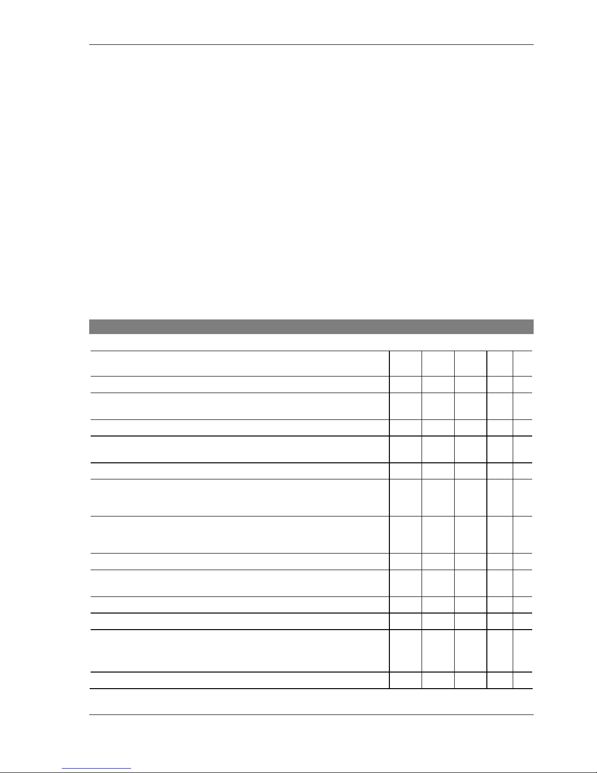
8 Test and maintenance scheduling
Frequency of intervention
Every
day
Every
month
Every 6
months
Every
year
see
§
Check for alarm messages.
¦
Check that the digital display panel i ndicates a value between 0 and
4C° (0 and 7° F)
¦
Test the purge
¦
3.4
Test the compressed air inlet temperature and compare to the maximum
value on the manufacturer's plate.
¦
Clean the purge filter *.
¦
5.1
Check that the temperature of the ambient air complies with mi nimum
and maximum values shown on the manufacturer's plate. Check that
the room is well ventilated.
¦
Check that when operating the temperature of the upper part of the
compressor is not too high (50C° Max). Test that the current consumed
by the drier complies with values on the manufacturer's plate.
¦
Clean the solenoid purge valve *
¦
5.2
Visually inspect the refrigerati ng circuit, the state of pipework and look
for oil slicks which can indicate a loss of refrigerant gas* pressure.
¦
4.2
Test the pipework connections.
¦
4.2
Test the condition of the electrical contacts and connections *.
¦
4.2
Check that the fan is not noisy.
Clean the condensing unit fins with a sponge or a clean compressed ai r
jet. Check that the grids are not dirty or clogged *.
¦
4.2
Clean the condensing unit fins with a non-aggressiv e detergent *.
¦
4.2
Page 14
CTA Instruction Manual MPE
Reference: MT0027DA This document may be modified without prior notice 14
Revision date: 11/05/06 Even partial reproduction is prohibited without authorisation in writing
Important:
• This schedul e is based on average operating conditions. In some cases it may be necessary to i ncrease
maintenance frequency.
• Clean the condensate purge fil ter on the purging system 1 week after start-up.
*You must comply with the recommendations at the beginning of this chapter.
9 Alarm
When temperature sensor is broken or short circuited, the first digit point (see di agram § 5.1) will blink and the
display show value ‘’00’’. In the same time, the compressor of the drier cut off.
Replace the broken sensor by a new one (do it without tension on the drier).
After sensor has been replaced, switch on the dryer, the display will show normal temperature and the
compressor will start after the 2 minutes delay.
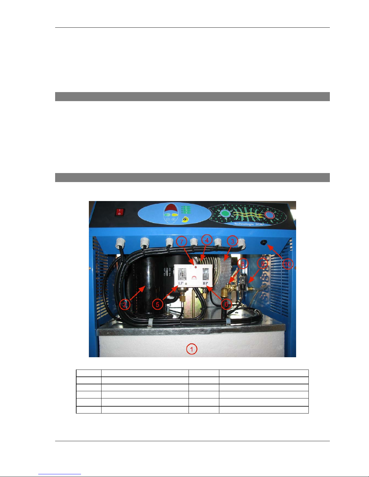
10 Components interns arrangement
Rep Description Rep Description
1 Thermical Mass 6 High Pressure switch
2 Compressor 7 High Pressure switch reset
3 Condenser 8 Valve + drain filter
4 Fan 9 Drain Solenoid valve
5 Low pressure switch 10 Compressor overload reset
Page 15
CTA Instruction Manual MPE
Reference: MT0027DA This document may be modified without prior notice 15
Revision date: 11/05/06 Even partial reproduction is prohibited without authorisation in writing
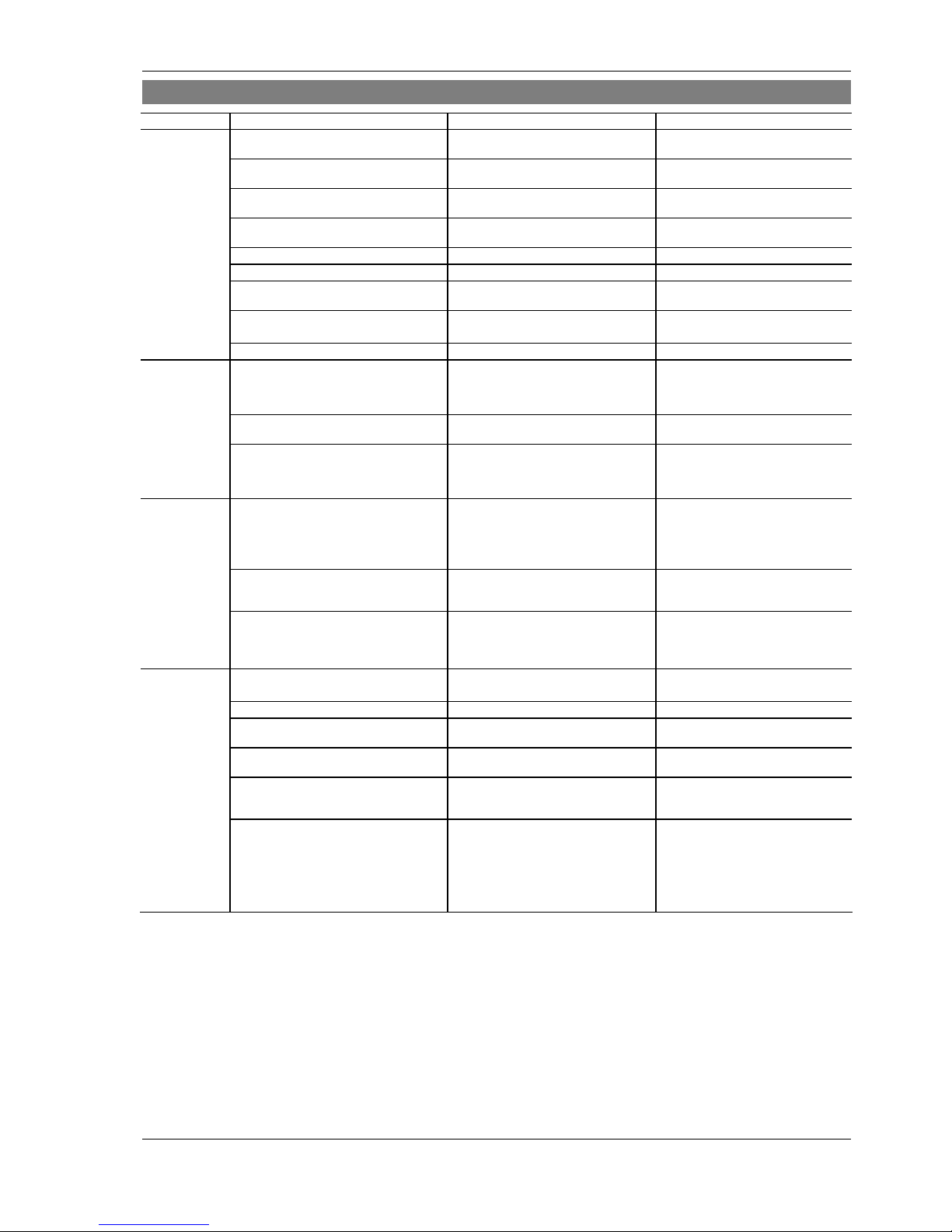
11 Troubleshooting
PROBLEM CAUSE SYMPTOM REMEDY
A. Dew point
too high
Compressed air temperature too high. The digital display pan el indicates
a value > 4C° permanently
Return the air inlet temperature to
within the limits.
Compressed air flow rate too high. Ditto Correct the air flow rate to within the
limits of the drier.
Compressed air pressure too low. Ditto Correct the pressure to within the
limits.
Ambient temperature Too high. Ditto Correct the temperature to within the
limits.
Dirty fins of the condenser. Ditto Clean the condensing unit fins.
Condensing unit face clogged. Ditto Clean the condensing unit face.
The fan runs backwards (three-phase) Ditto Correct electrical connection (phase
inversion)
Refrigerant gas leak • The compressor runs all the time
• The compressor top is very hot;
Find the leak and repair it.
The HP Pr essure s witch has tripped The digital display pan el is OFF See note E.
B.
Excessive drop
in compressed
air pressure.
Compressed air flow rate too high. Pressure downstream from the drier
lower than the expected value.
Reduce the compressed air flow
rate.
Condensates Frozen. Pressure downstream from the drier
lower than the expected value.
See note C.
Exchanger Tubes soiled by impurities in
the compressed air.
Pressure downstream from the drier
lower than the expected value.
Wash the heat exchanger tubes with
a non-aggressive detergent solution.
Check the filter upstream from the
drier.
C.
Compressed air
does not flow
through the
drier.
The condensates have frozen and block
the passage as the probe is incorrectly
positioned.
Compressed air does not flow through
the drier.
Position the probe in the centre of
the DTM heat exchanger.
The condensates have frozen and block
the passage as the set point is
programmed too low.
After the starting the compressor, value
0 is reached in less than 2 minu tes.
Increase the set point value.
The condensates have frozen and block
the passage as the electronic controller
has failed.
The compressor stops.
The compressor does not stop even if
the digital display panel indicates 0
several minutes.
See note H.
Change the electronic board
D.
The solenoid valve coil has failed. No condensates or air are expelled
when the TEST Button is pressed.
Replace th e solenoid valve coil.
The purge circuit is clogged The purge filter is dirty. Clean the filter
The soleno id purge valve opening time is
insufficiently long time.
No condensates or air are expelled
when the TEST Button is pressed.
Increase the duration for which the
solenoid purge valve open s.
Solenoid valve plug clogged. No condensates or air are expelled
when the TEST Button is pressed.
Clean the solenoid valve
The relay on the electronic board which
controls the solenoid valve does no t
function.
Use a voltmeter to check if the relay
contacts do not close when the TEST
button is pressed
Replace the electronic board if the
relay does not function.
Distribution network pipework is in a "cold"
environment in which the temperature is
lower than the dew point temperature of
the compressed air under pressure and
the tubes are not lagged. In this case,
condensates form on the internal surfaces
of the pipes.
The drier functions problem-free.
The cause of the problem is external.
Lag the pipework in "cold"
environments.
Condensates
present
downstream
from the drier
Page 16
CTA Instruction Manual MPE
Reference: MT0027DA This document may be modified without prior notice 16
Revision date: 11/05/06 Even partial reproduction is prohibited without authorisation in writing
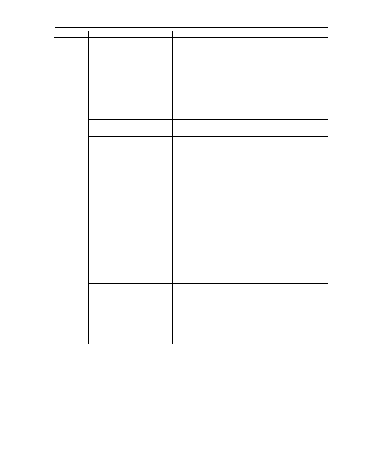
PROBLEM CAUSE SYMPTOM REMEDY
E.
HP Pressure
switch cuts in
The motorised fan does not function. All the LEDs on the electronic board are
OFF as if the power supply had failed.
Repair or replace the fan. Press the
red re-set button on the pressure
controller.
(manual) Ambient temperature Too high. Ambient air temperature conditions
higher than maximum authorised value
Return the ambient temperature to
within the limits by, for example,
increasing room ventila tion. Press the
red re-set button on the pressure
controller.
Recirculation of hot air due to incorrect
installation.
Very high temperature in room Modify the position of the machine or
the obstructions to eliminat e air
recirculation. Press the red re-set
button on the pressure controller.
Condens ing unit fins dirty. The digital displa y panel continuously
indicates a value
> 4°C.
Clean the condensing unit fins.
Press the red re-set button on the
pressure controller.
Condens ing unit face clogged. The digital display panel indicates
a value > 4°C continuously
Clean the condensing unit front face.
Press the red re-set button on the
pressure controller.
Relatively high ambient air Temperature
and fan t urning in wrong direction (if
three-phase power supply).
Cooling air passes first passes through
the fan and then through the
condensing unit.
Reverse two machine power supply
phases.
Press the red re-set button on the
pressure controller.
compressed air flow rate or temperature
too high and high ambient temperatures
at the same time.
High dew point (which means a high
evaporation pressure of raised and
higher purging from the separator).
Correct the temperature and the air
flow to pre-set limits .
Press the red button on the Pressure
switch cap.
F.
Low pressure
(LP) Pressure
switch cuts in.
(auto.)
Refrigerant leak The compressor stops before cooling the
thermal mass to the pre-set value or
compressor stop and start many times.
Have the circuit checked for leaks by
a refrigeration technician and
eliminate them.
Have a refrigeration technician Refill
the circuit.
After each LP switch cut, no display
during 2 minutes and compressor start
automatically 2 minutes after.
On first start-up if the ambient
temperature is too low and the thermal
mass is at the same temperature as the
ambient temperature.
Ditto Correct the ambient temperature by
raising it above the minimum set point
value.
G.
Compressor
protection
system cuts in.
Compressed air flow rate and
temperature too high and high ambient
temperature at the same time.
• The compressor head and body are
very hot;
• the compressor stops and tries to start
up again a few seconds later.
Shut the compressor down and adjust
compressed air flow rate and pressure
to within the drier lim its.
Wait a few minutes before starting up
the compressor again
Check and replace the HP Pressure
switch if necessary.
Compressed air flow rate and
temperature too high and refrigerating
circuit empty.
• The compressor head and body are
very hot;
• the compressor stops and tries to
start up again a few seconds later.
Have the circuit checked for leaks by
a refrigeration technician, refill the
circuit.
Check and replace the HP Pressure
switch if necessary.
The HP Pressure switch has failed. Ditto Check and replace the HP Pressure
switch if necessary.
H.
Sensor
protection
system cuts in
The compressor has stopped the control
board display show 00 and the first digit
point is blin king.
The temperature sensor is not
connected or short circuited
Page 17
CTA Instruction Manual MPE
Reference: MT0027DA This document may be modified without prior notice 17
Revision date: 11/05/06 Even partial reproduction is prohibited without authorisation in writing
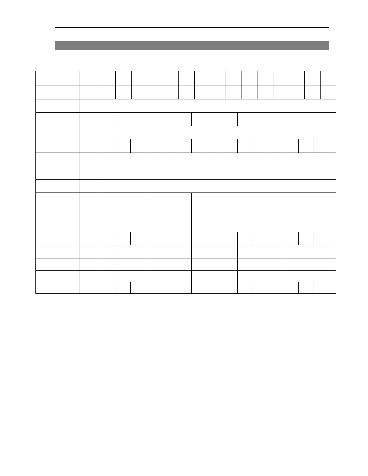
12 Design specifications
Model MPE 004 006 008 010 015 020 025 030 040 050 060 075 100 125 150
Flow rate* m3/h 30 48 70 100 140 175 210 260 300 420 540 660 780 920 1020
Max. Pressure bar 16
Connection BSP ½" ¾" 1" 1"1/2 2" 2"1/2
Power supply 230/1/50
Max. current kW 0.3 0.5 0.7 0.75 0.84 1.05 1.1 1.3 1.5 1.85 2.2 2.4 2.8 3.2 3.50
Refrigerant Fluid R134a R407c
Load gr see on the data sticker at the back panel
HP Pressure switch
bar 18 26 (Manual Reset)
LP pressure
controller
bar - 1 (automatic)
Fan Pressure
Switch
bar - 14 / 18
Dimensions
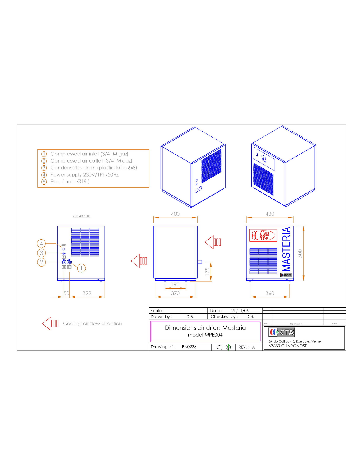
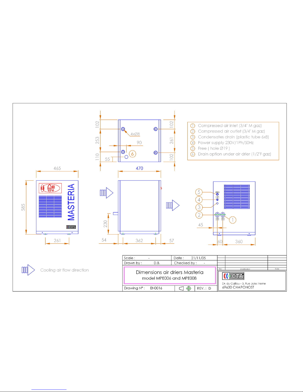
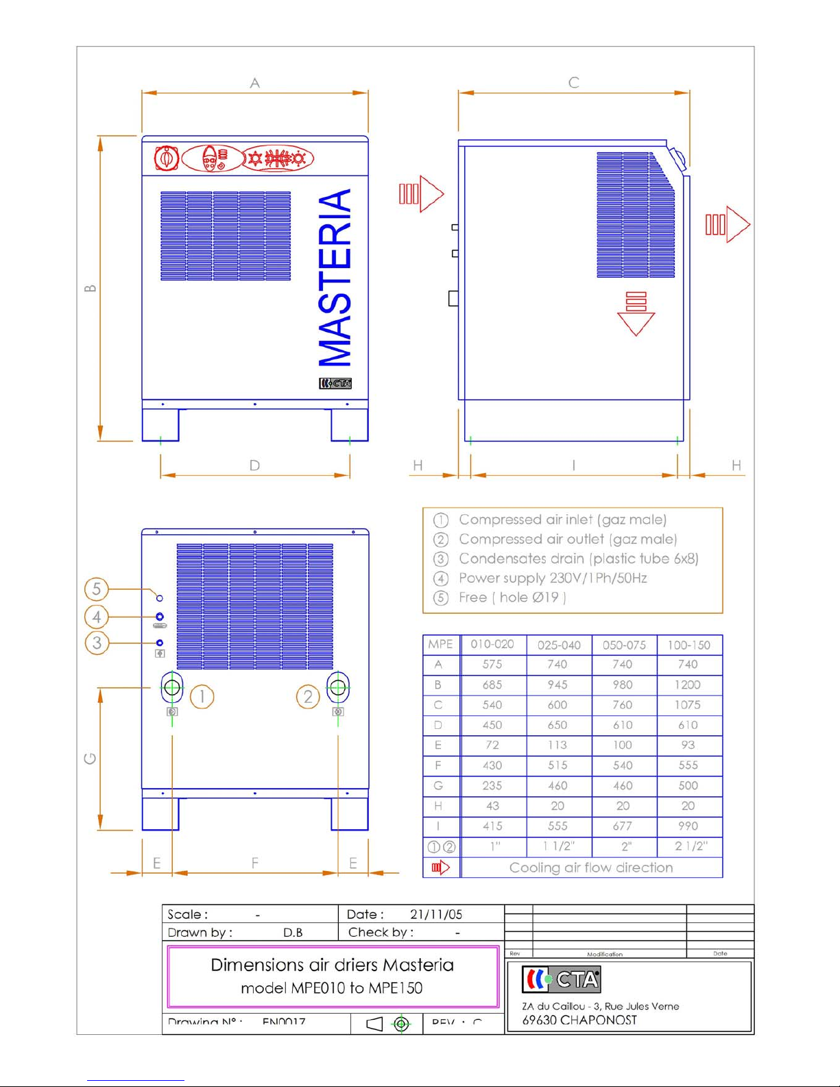
Width mm 430 465 575 740 740 740
Height mm 430 585 685 945 980 1200
Depth mm 430 470 540 600 760 1075
Weight Kg 35 52 55 81 83 86 169 174 178 215 220 226 345 351 360
* Nominal flow rate expressed to 1 absolute bar, 20°C as stipulated in ISO 7183 IN the FOLLOWING conditions:
• Air inlet temperature: 35°C
• Operating pressure: 7 bars
• Ambient temperature: 25°C
• Relative humidity: 60%
• Exhaust dew point: +3°C under pressure (-21°C at atmospheric pressure).
Page 18
CTA Instruction Manual MPE
Reference: MT0027DA This document may be modified without prior notice 18
Revision date: 11/05/06 Even partial reproduction is prohibited without authorisation in writing
13 Appendices
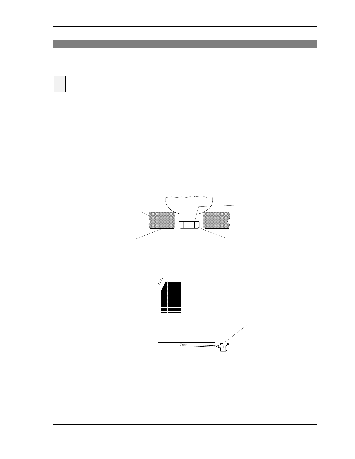
13.1 Use of a purge with a level detection function
Various risks (electrocution, explosion...): The following operations must only be carried out by
personnel qualified in electrical and pneumatic systems.
Before installation, the operations described in § 4.1 and 4.2 must be carried out.
After installation, the operations described in § 4.3 and 4.4 must be carried out.
Your Mastéria drier is pre-fitted for an external purge with a level detection system. To connect this type of
purge, you must:
1. Raise your drier sufficiently to enable the purge to be fitted underneath with creating a water pocket.
2. Remove the lower plug on the condensate separator.
3. To connect pipework to feed condensates to the external purge.
To use your external purge correctly, refer to the manufacturer's instructions.
4. Close the manual valve on the internal sequential purge.
This will inhibit the electronic board from opening and closing it.
Separator base
Dryer fitted with an external drain
!
Drain
Plug
Connection 1/2" F
Bodywork
Isolator
Page 19
CTA Instruction Manual MPE
Reference: MT0027DA This document may be modified without prior notice 19
Revision date: 11/05/06 Even partial reproduction is prohibited without authorisation in writing
14 Circuit diagrams
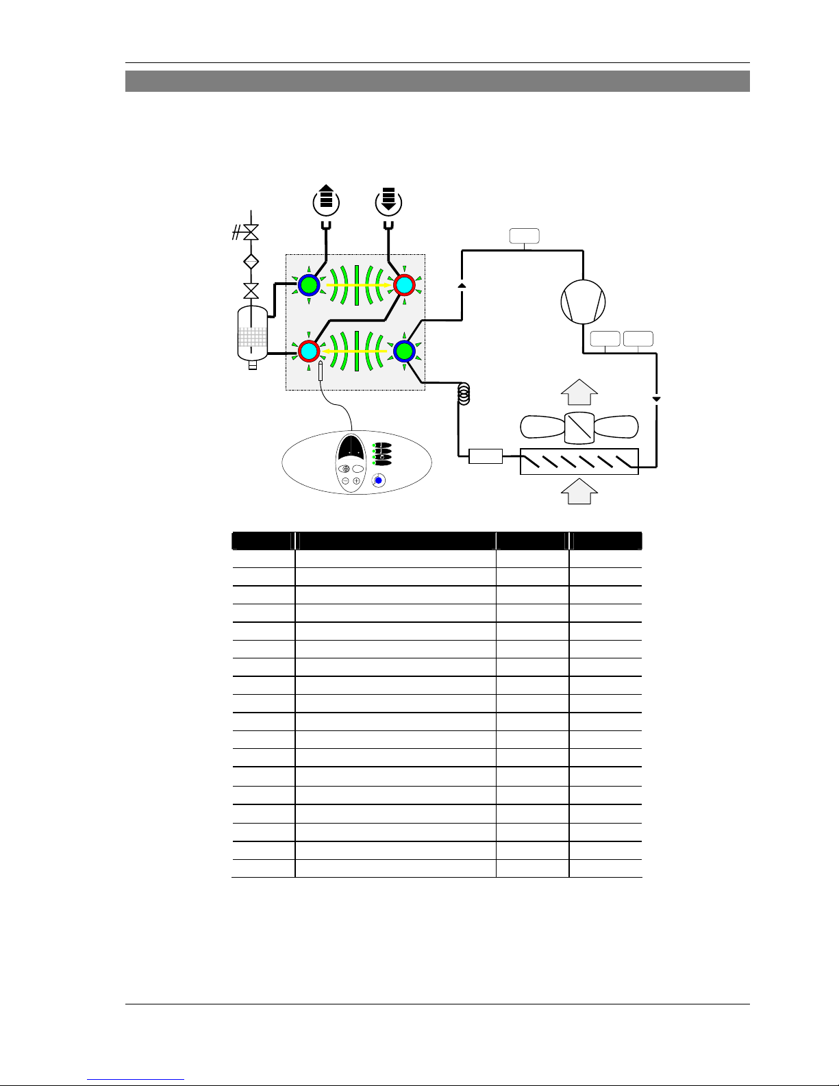
14.1 Refrigeration/pneumatic circuit diagram (SC0014A)
Label Components 006-020 025-125
AO Compressed air exhaust
∏ ∏
AI Compressed air inlet
∏ ∏
CD Condensing unit
∏ ∏
CF Condensate filter
∏ ∏
CO Condensate discharge
∏ ∏
CP Compressor
∏ ∏
CS Condensate separator
∏ ∏
CT Capillary tube
∏ ∏
OF DTM® heat exchanger
∏ ∏
DF Dehydrator filter
∏ ∏
EB Electronic board
∏ ∏
F Fan
∏ ∏
FPS Fan Pressure switch
∏
HPS High pressure switch
∏ ∏
LPS Low pressure switch
∏
MV Manual valve
∏ ∏
RS Probe regulation
∏ ∏
SV Solenoid purge valve
∏ ∏
HPS
CD
F
CP
DF
FPS
LPS
ζ
ζ
EB
CS
MV
DE
SV
CF
CT
RS
ζ
AO
AI CO
Page 20
CTA Instruction Manual MPE
Reference: MT0027DA This document may be modified without prior notice 20
Revision date: 11/05/06 Even partial reproduction is prohibited without authorisation in writing
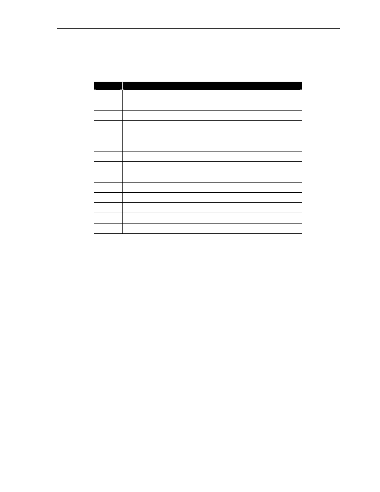
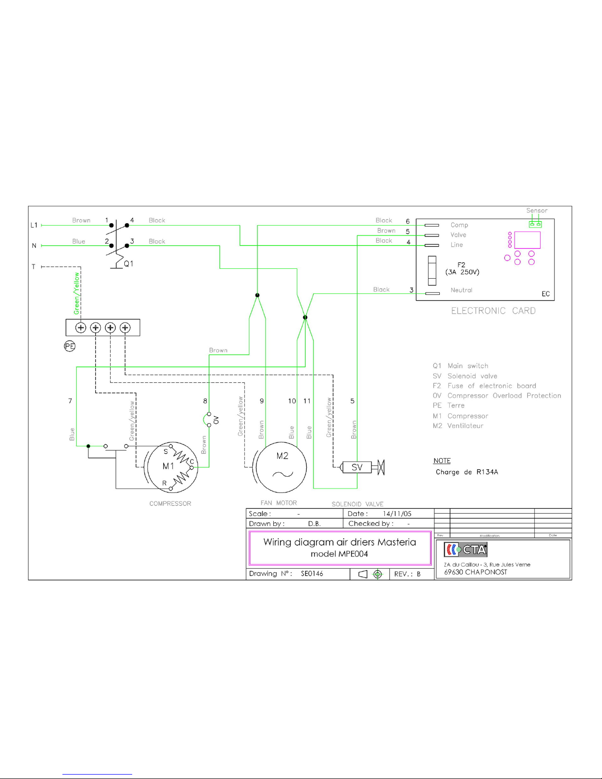
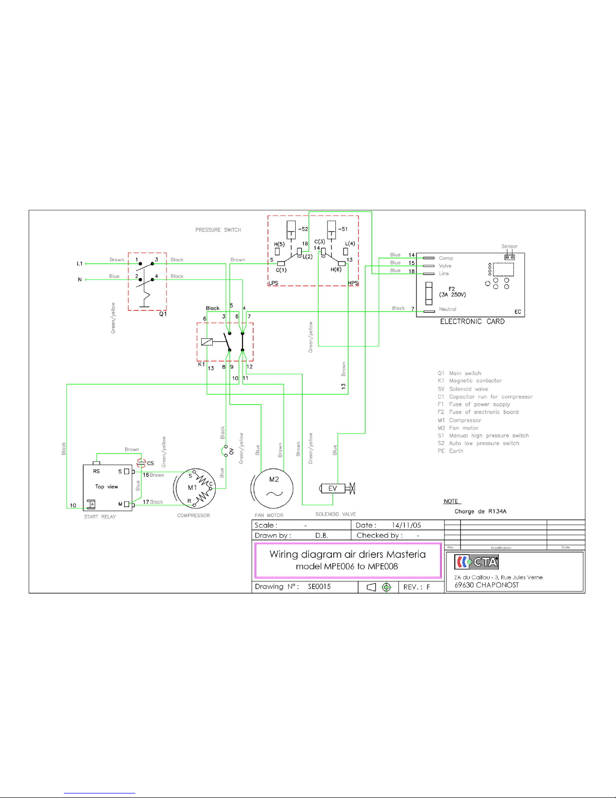
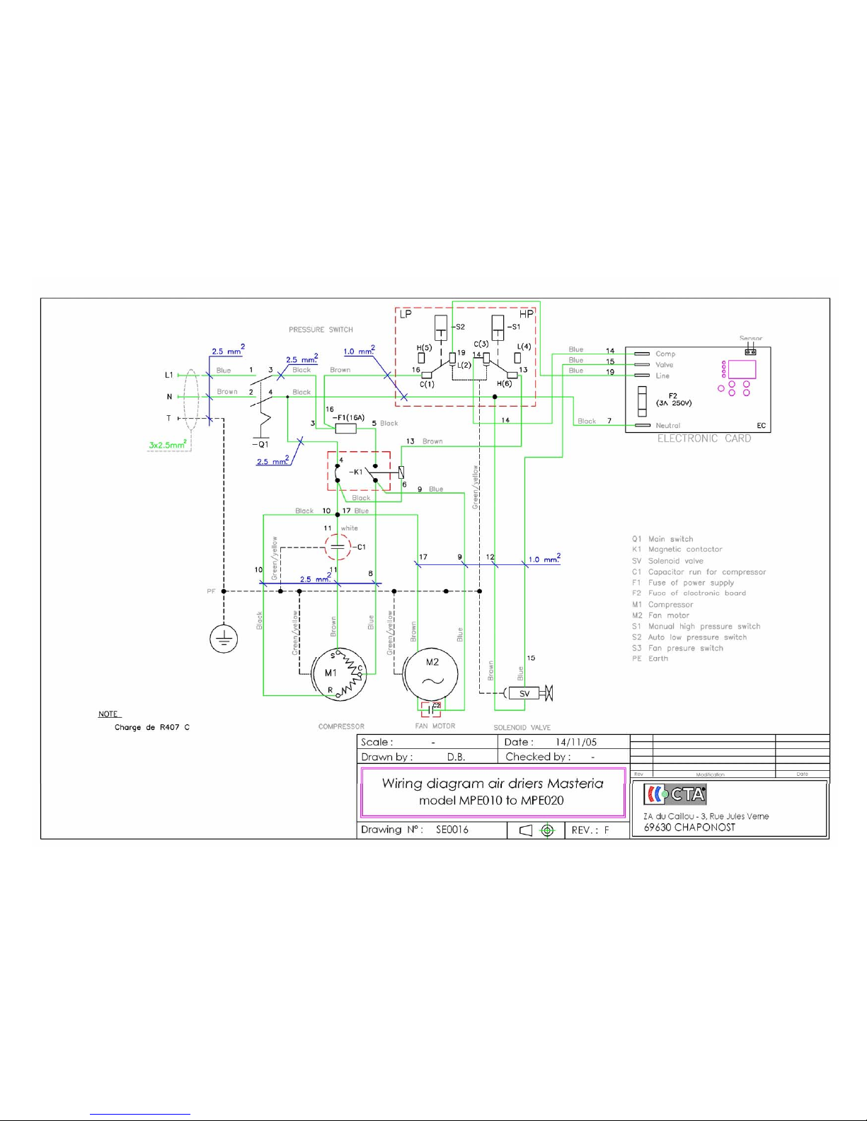
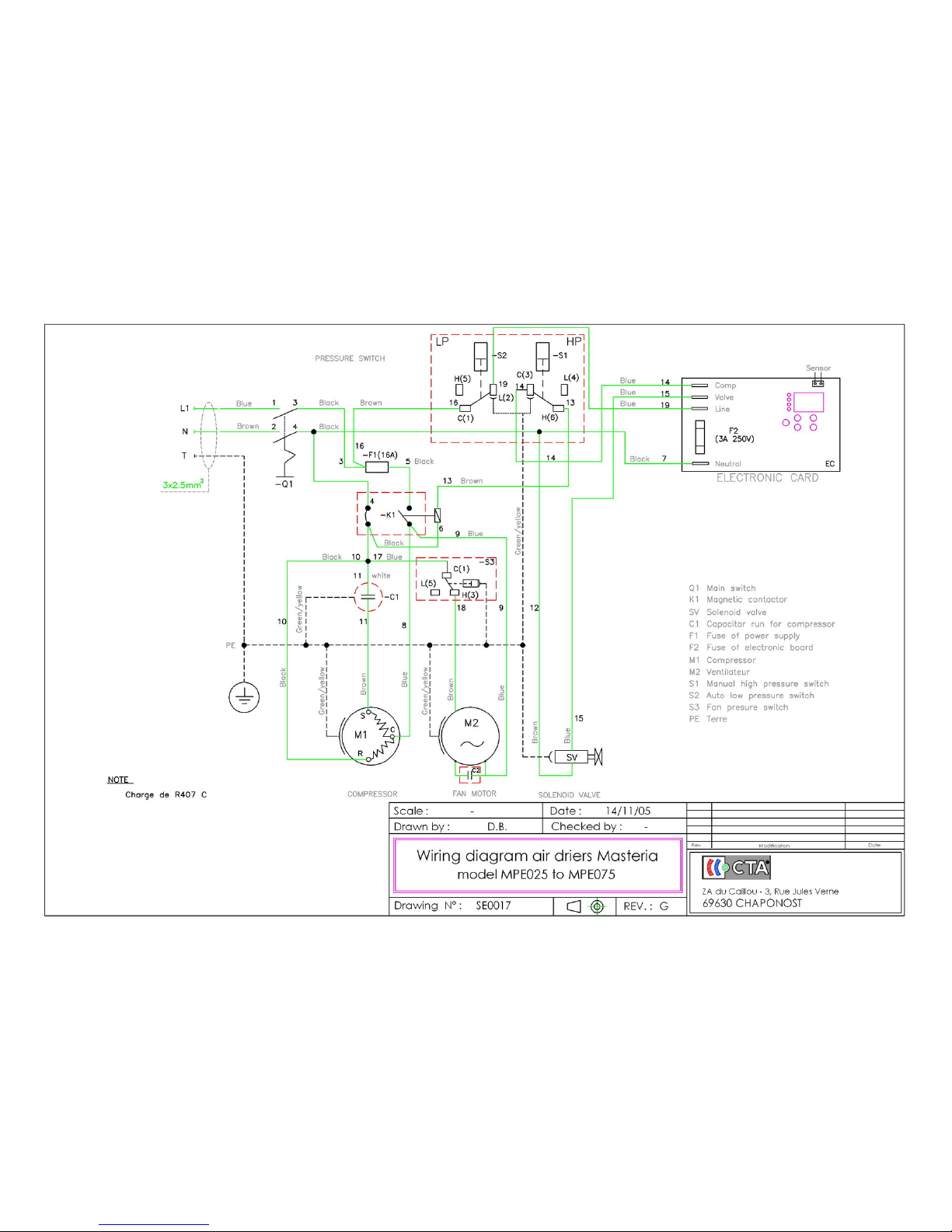
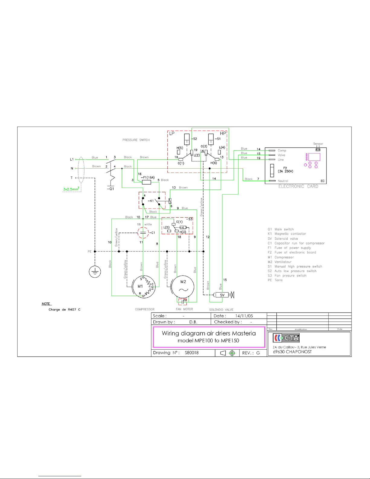
14.2 Wiring diagrams (SE00148, SE0015, SE0018, SE0017 and SE0018)
Label Components
M1
Compressor
M2
Fan motor
EC
Electronic card
EV
Solenoid purge valve
HPS
High pressure switch
LPS
Low pressure switch
FPS
Fan pressure switch
Q1
General switch
F
Fuse for the electric power part of the dryer
K1
Power contactor
CS
Start capacitor
CR
Run capacitor
OV
Compressor overload protection
RS
Start relay
Page 21
Page 22
Page 23
Page 24
Page 25
Page 26
Page 27
Page 28
 Loading...