

Page 1

PC300 Series
PC Module
Page 2

PC300 / PC311E(P) l User’s Manual
Table of Contents
Prefaces …………………………………………………….……………………………………………. 04
Revision …………………………………………………………………………………………..……………….……….. 04
Disclaimer ………………………………………………………..…….…….………………………….……………….. 04
Copyright Notice …………………………………….…………………….…………………………………………… 04
Trademarks Acknowledgment …………..………………………………………………………...................04
Environmental Protection Announcement …………………………….………………….……………….. 04
Safety Precautions ………………………………………….……………………………….…………….………….. 05
Technical Support and Assistance …………………………………….…………….…………….…………….06
Conventions Used in this Manual ………………………………………………………………….….………..06
Package Contents …………………………………………………………………………………………….…………07
Ordering Information …………………………………….……………………………………….……….………… 07
Optional Accessory …………...……………………………………..................................................... 07
Chapter 1 Product Introductions ………………………………………………………..… 08
1.1 Overview ……………………….………………………………..………….………………..……….. 09
1.1.1 Key Feature ………….……………………………………….……….…..………..…....... 09
1.2 Hardware Specification ….………………………….....…………….…………..…..………… 10
1.3 System I/O ……………………………..……………………..…………………………………..…… 11
1.3.1 PC300 …………………………………......................……………………………….……11
1.3.2 PC311E / PC311P …………….………………………………………………..…………... 13
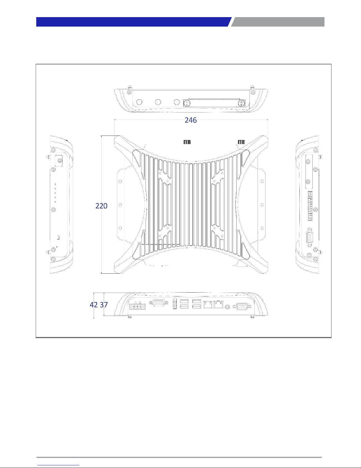
1.4 Mechanical Dimension …………………………..…………………………..………….………. 16
1.4.1 PC300 …………………………………......................…………………………………… 16
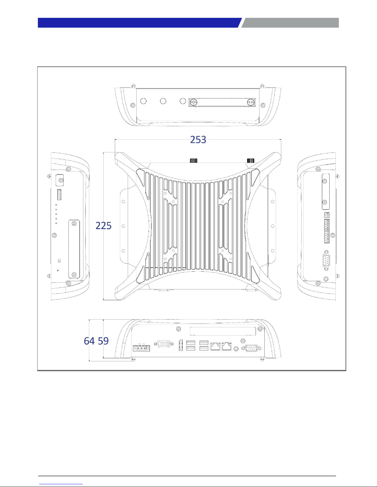
1.4.2 PC311E / PC311P …………….………………………………………………..…………... 17
Chapter 2 Switches and Connectors ……..…………………………………………..…. 18
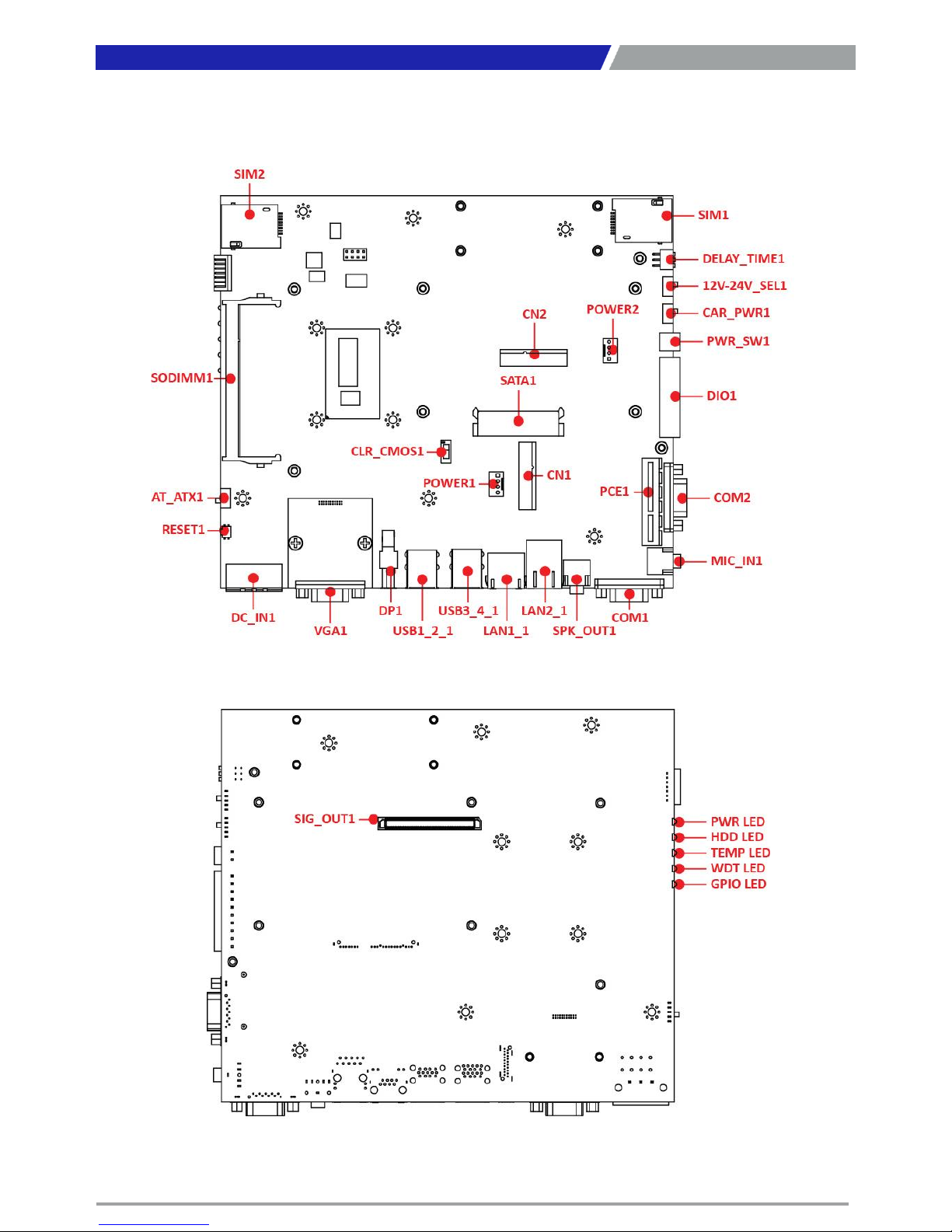
2.1 Switch and Connector Locations ……………………………………..…….…..……..….... 19
2.1.1 Top View ……………………………………………………………………....……………… 19
2.1.2 Bottom View ……………………………………………………………………....……….. 19
2.2 Connector / Switch Definition ……………………………….……….…….………............ 20
2.3 Switch Definitions ………….…………….............................................................. 21
2.4 Connector Definitions …………………………...................................................... 23
Chapter 3 System Setup ……………………..………………………………………..……… 32
3.1 Set torque force to 3.5 kgf-cm to execute all the screwing and
unscrewing. ……….………………………………………………………………………………….... 33
3.2 Removing chassis top cover …………………………………………………..………………... 33
3.3 Installing SODIMM …………………………………………………………………………………...34
3.4 Installing mini PCIe card / mSATA ……………………………………….…………………...35
3.5 Installing antenna ……………………………………………………………….…………………...36
3.6 Installing PCIe/PCI expansion card (Only for PC311E & PC311P) ………..…... 38
3.7 Assembly chassis top cover ………………………………………………..…………………...40
3.8 Installing HDD on removable SATA HDD bay …………………………….……………... 41
3.9 Installing SIM card ……………………………………………………………….…………………...43
3.10 Connecting PC module with VIO display module ……………………..……………... 45
3.11 Screw location for PC311 series top cover …………………………….………………... 46
2
Page 3

PC300 / PC311E(P) l User’s Manual
Chapter 4 BIOS Setup ……………………..……………………………………..……………. 47
4.1 BIOS Introduction ………………………………………..…….…………………………..…….... 48
4.2 Main Setup ………………………………………..…….…………….…………………………….... 49
4.2.1 System Language …….……………………………………..……..…………..……….... 49
4.2.2 System Date …….……………………………………………..……..………….……….... 49
4.2.3 System Time ………..…………………………………………..……….………..………... 49
4.3 Advanced Setup ………………………………………………………..…………………..……….. 50
4.3.1 CPU Configuration……..…………………………………………………..…..…………. 50
4.3.2 Trusted Computing (Option) ……………..…….………..…..……………..……... 51
4.3.3 ACPI Settings ……………….………..…………………………….………………..……... 52
4.3.4 Super IO Configuration ……………….………..………………..……………..……... 52
4.3.5 Hardware Monitor ……………….………..………………………….……..…..……... 55
4.3.6 Serial Port Console Redirection ……………….………..……………..…..……... 56
4.3.7 SATA Configuration ……………….………..…………………..………..……..……... 56
4.3.8 Network Stack Configuration ……………….……..…..…………………..……... 57
4.3.9 CSM Configuration ……………….………..………………………..…………..……... 58
4.3.10 USB Configuration ……………….………..…………………….……………..……... 59
4.3.11 Intel(R) Ethernet Connection I218-LM-XX:XX:XX:XX:XX:XX ….……... 60
4.3.12 Intel(R) I210 Gigabit Network Connection- XX:XX:XX:XX:XX:XX …... 61
4.4 Chipset …………...……….………………….…..….…..…………..…………………………..….... 62
4.4.1 System Agent (SA) Configuration ………………….…………..………………….. 62
4.4.2 PCH-IO Configuration ………….…………………………………..…………………….. 64
4.5 Security …………...……….………………….…..….…..………………………..……..…………... 67
4.5.1 Administrator Password …….…………………………………..…………………….. 67
4.5.2 User Password …….……………………………….………………..…………………….. 67
4.6 Boot …………...……….….………………….…..…………………………..…………..……………...68
4.6.1 Setup Prompt Timeout ………………………..…………..……………………………..68
4.6.2 Bootup NumLock State ………………………………………………..………………… 68
4.6.3 Quiet Boot ………………………….……………………….…………………..…...………. 68
4.6.4 Fast Boot …………………………..…………………………………………………………... 68
4.6.5 Hard Driver BBS Priorities …………………………..……………………….………... 68
4.7 Save & Exit …………...……….….………………………………………..…………..……………... 69
4.7.1 Save Changes and Reset …………………..…………..…………………………….. 69
4.7.2 Discard Changes and Reset ……………………………………..………………… 69
4.7.3 Restore Defaults ………………………….…………….…………………..…...………. 69
4.7.4 Launch EFI Shell from filesystem device ………………………………………... 69
Appendix WDT & GPIO …………………………………………………………………………… 70
WDT Sample Code …….……………………….……………….……………..….…….…….…………... 71
GPIO Sample Code ………………………………………………………..…………………………………. 72
3
Page 4
PC300 / PC311E(P) l User’s Manual
4
Revision
Disclaimer
All specifications and information in this User’s Manual are believed to be accurate and up to date. C&T
Solution Inc. does not guarantee that the contents herein are complete, true, accurate or non-misleading.
The information in this document is subject to change without notice and does not represent a
commitment on the part of C&T Solution Inc.
C&T Solution Inc. disclaims all warranties, express or implied, including, without limitation, those of
merchantability, fitness for a particular purpose with respect to contents of this User’s Manual. Users must
take full responsibility for the application of the product.
Copyright Notice
All rights reserved. No part of this manual may be reproduced or transmitted in any form or by any means,
electronic or mechanical, including photocopying, recording, or information storage and retrieval systems,
without the prior written permission of C&T Solutions Inc. Copyright © 2015 C&T Solutions Inc.
Trademarks Acknowledgment
Intel®, Celeron® and Pentium® are trademarks of Intel Corporation.
Windows® is registered trademark of Microsoft Corporation.
AMI is trademark of American Megatrend Inc.
IBM, XT, AT, PS/2 and Personal System/2 are trademarks of International Business Machines Corporation
All other products and trademarks mentioned in this manual are trademarks of their respective owners.
Environmental Protection Announcement
Do not dispose this electronic device into the trash while discarding. Please recycle to minimize pollution
and ensure environment protection.
Prefaces
Revision
Description
Date
1.0
Manual Released
2017/09/12
1.1
GPIO Sample Code Revised
2018/02/09
Preface
Page 5

PC300 / PC311E(P) l User’s Manual
5
Safety Precautions
Before installing and using the equipment, please read the following precautions:
Put this equipment on a reliable surface during installation. Dropping it or letting it fall could
cause damage.
The power outlet shall be installed near the equipment and shall be easily accessible.
Turn off the system power and disconnect the power cord from its source before making any
installation. Be sure both the system and the external devices are turned OFF. Sudden surge
of power could ruin sensitive components. Make sure the equipment is properly grounded.
When the power is connected, never open the equipment. The equipment should be opened
only by qualified service personnel.
Make sure the voltage of the power source is correct before connecting the equipment to the
power outlet.
Disconnect this equipment from the power before cleaning. Use a damp cloth. Do not use
liquid or spray detergents for cleaning.
Avoid the dusty, humidity and temperature extremes.
Do not place heavy objects on the equipment.
If the equipment is not used for long time, disconnect it from the power to avoid being
damaged by transient over-voltage.
The storage temperature shall be above -40°C and below 80°C.
The computer is provided with a battery-powered real-time clock circuit. There is a danger of
explosion if incorrectly replaced. Replace only with the same or equivalent type
recommended by the manufacturer.
If one of the following situation arises, get the equipment checked be service personnel:
• The power cord or plug is damaged.
• Liquid has penetrated into the equipment.
• The equipment has been exposed to moisture.
• The equipment does not work well or it cannot work according the user’s manual.
• The equipment has been dropped and damaged.
• The equipment has obvious signs of breakage.
Preface
Page 6
PC300 / PC311E(P) l User’s Manual
6
Technical Support and Assistance
1. Visit the C&T Solution Inc website at www.candtsolution.com where you can find the latest
information about the product.
2. Contact your distributor, our technical support team or sales representative for technical support if
you need additional assistance. Please have following information ready before you call:
Model name and serial number
Description of your peripheral attachments
Description of your software (operating system, version, application software, etc.)
A complete description of the problem
The exact wording of any error messages
Conventions Used in this Manual
Preface
This indication alerts operators to an operation that, if not strictly observed,
may result in severe injury.
WARNING
This indication alerts operators to an operation that, if not strictly observed,
may result in safety hazards to personnel or damage to equipment.
CAUTION
This indication provides additional information to complete a task easily.
NOTE
Page 7

PC300 / PC311E(P) l User’s Manual
7
Package Contents
Before installation, please ensure all the items listed in the following table are included in the package.
Item
Description
Q’ty
1
PC300 Series PC Module
1
2
Utility DVD Driver
1
3
Screw Pack
1
Preface
Ordering Information
Model No. Product Description
PC300-5350U PC Module for Industrial Display System with Intel® i5-5350U Processor
PC300-5010U PC Module for Industrial Display System with Intel® i3-5010U Processor
PC300-3765U
PC Module for Industrial Display System with Intel® Celeron® 3765U
Processor
PC311E-5350U
PC Module for Industrial Display System with Intel® i5-5350U Processor,
1x PCIe x4 Expansion
PC311E-5010U
PC Module for Industrial Display System with Intel® i3-5010U Processor,
1x PCIe x4 Expansion
PC311E-3765U
PC Module for Industrial Display System with Intel® Celeron® 3765U
Processor, 1x PCIe x4 Expansion
PC311P-5350U
PC Module for Industrial Display System with Intel® i5-5350U Processor,
1x PCI Expansion
PC311P-5010U
PC Module for Industrial Display System with Intel® i3-5010U Processor,
1x PCI Expansion
PC311P-3765U
PC Module for Industrial Display System with Intel® Celeron® 3765U
Processor, 1x PCI Expansion
Optional Accessories
Model No. Product Description
1
-E09A06002
Adapter AC/DC 12V 5A 60W with 3pin Terminal Block Plug 5.0mm Pitch
SFICBL022
Power Cord, 3
-pin US Type, 180cm
1
-TPCD00002
Power Cord, European Type, 180cm
1
-TPCD00001
Power Cord, 3
-pin UK Type, 180cm
Page 8

Chapter 1
Product Introductions
Page 9
PC300 / PC311E(P) l User’s Manual
9
1.1 Overview
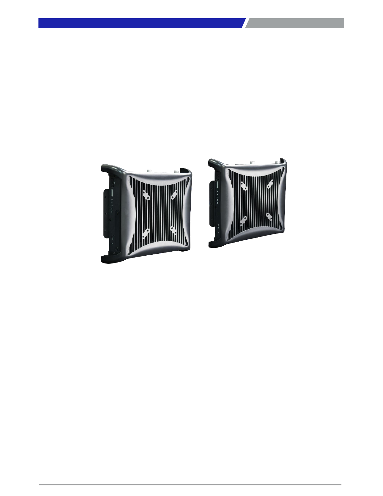
The PC300 series PC module is based on 5thGen. Intel® Core™ i5-5350U (2.9GHz) / i3-5010U (2.1GHz)
or Celeron® 3765U (1.9GHz) Dual Core processor. It supports Multi-Mode Display Module (MDM)
technology which makes it more flexible in system maintaining and upgrading. It also offers modularize
expansion I/O, rich connectivity interfaces, wide range (9~48V) DC power input, and high reliability
even operating in temperature extremes (-40~+70°C).
Featuring with completely cable-less designed and high functional, PC300 series are ruggedized display
systems that can operate in harsh environments and easy to install and maintain. A build in over
voltage protection (OVP), over current protection (OCP), reserve voltage protection, and wide range DC
power input makes PC300 series are safety system for all industrial applications.
Chapter 1: Product Introductions
1.1.1 Key Features
Intel® Core™ Processor i5-5350U, up to 2.9GHz / i3-5010U, 2.1GHz or Celeron® 3765U, 1.9GHz
1x 204-pin DDR3L SODIMM. Max up to 8GB
1x 2.5” Removable SATA HDD bay support RAID 0,1, 5, 2x mSATA, 2x SIM socket
2x Full-size mini PCIe for communication or expansion modules
1x PCIe x4 (PC311E Only)
1x PCI (PC311P Only)
2x LAN
1x LVDS, 1x VGA, 1x DisplayPort
1x LVDS, 1x DVI-D, 1x DisplayPort (Optional)
2x External RS-232/422/485, 2x Internal RS-232/422/485
3x USB 3.0, 1x USB 2.0
4x Isolated Digital Input, 4x Isolated Digital Output
9 to 48VDC wide range power input
-40°C to 70°C extended operating temperature
PC300
PC311E / PC311P
Page 10

PC300 / PC311E(P) l User’s Manual
10
1.2 Hardware Specification
Chapter 1: Product Introductions
Processor System
• Onboard Intel® Core ™ i5-5350U / Core™ i3-5010U /
Celeron ® 3765U Dual Core Processor, 2.9 / 2.1 / 1.9GHz
with AMI 64Mbit SPI BIOS
Memory
• 1x 204-Pin DDR3L-1333 / 1600MHz SO-DIMM
(un-buffered and non-ECC), Max. up to 8GB
Display
Triple Display
• 1x LVDS, 1x VGA, and 1x DisplayPort
Expansion
• 1x PCIe X4 (PC311E Only)
• 1x PCI (PC311P Only)
• 2x Full-size Mini PCIe Socket for Wi-Fi / GSM / Expansion
Module
• 1x Universal I/O Bracket (PC311E, PC311P Only)
Ethernet
• 1x Intel® i210-AT GbE LAN Port, Support Wake-on-LAN
and PXE
• 1x Intel® I218-LM GbE LAN Port, Support Wake-on-LAN
and PXE
Audio
• Codec: Realtek ALC888S
• 1x Mic-in and 1x Speaker-out
Watchdog Timer
• Software Programmable Supports 1~255 sec. System
Reset
Storage
• 1x Removable 2.5" SATA HDD Bay
• 2x Internal mSATA Slot (Shared by 2x Mini-PCIe Socket)
• 2x External SIM Card Socket
• Support RAID 0, 1, 5
I/O Ports
• 3x USB 3.0 Port
• 1x USB 2.0 Port
• 4x Isolated DI and 4x Isolated DO Port
• 2x External DB9 for COM1~2, Support RS232/422/485
with Auto Flow Control
• 2x Internal COM3~4, Support RS232/422/485 with Auto
Flow Control
• 3x Antenna Hole
• 1x AT/ATX Switch
• 1x Remote Power on/off Connector
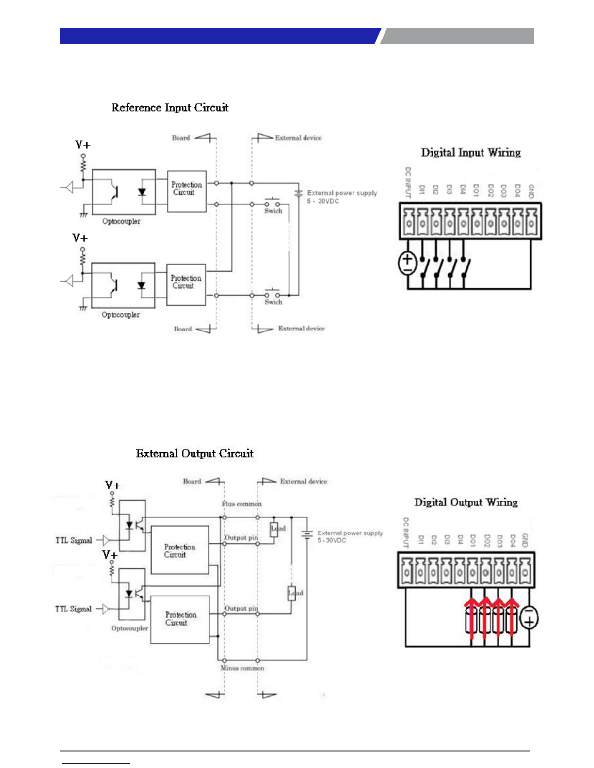
Digital Input & Output
• 4x Digital Input (Source Type)
- Input Voltage (Dry Contact):
Logic 0: Close to GND
Logic 1: Open
- Input Voltage:
Logic 0: 3V max.
Logic 1: 5V min. (DI to COM-)
• 4x Digital Output
- Supply Voltage: 5~30VDC
- Sink Current: 200 mA Max. Per Channel
Power
• Support AT, ATX Mode
• 1x 3-pin Terminal Block Connector with Power Input
9~48VDC
• Power Ignition Sensing
• 1x Optional AC/DC 12V/5A, 60W Power Adapter
Environment
• Operating Temperature: Ambient with Air Flow:
-40°C to 70°C (with Industrial Grade Peripherals)
• Storage Temperature: -40°C to 80°C
• Relative humidity: 10%~95% (non-condensing)
Physical
• PC300 Series
- Dimension (WxDxH, mm): 246 x 220 x 42mm
- Weight: 1.68kg
• PC311E / PC311P Series
- Dimension (WxDxH, mm): 246 x 220 x 59mm
- Weight: 2.21kg
• Construction: Extruded Aluminum with Heavy Duty
Metal
• Mounting: VESA Mounting Holes 75 x 75mm, 100 x
100mm
Operating System
• Windows® 7
• WES7
• Windows® 8.1
• WES8.1
• Windows 10
• Linux kernel 3.X
Certifications
• CE
• FCC Class A
Page 11
PC300 / PC311E(P) l User’s Manual
11
1.3 System I/O
1.3.1 PC300
Chapter 1: Product Introductions
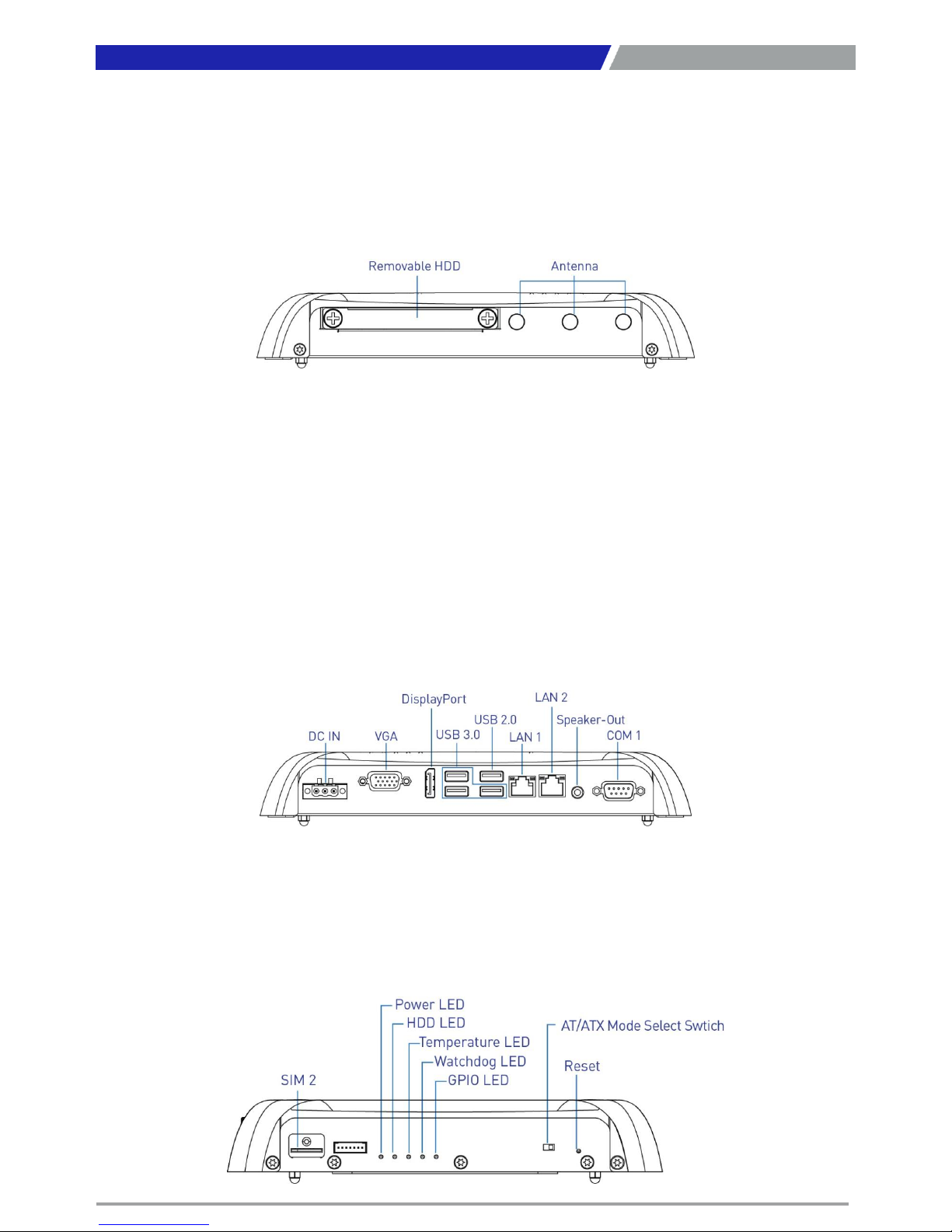
Rear Panel
DC IN
Used to plug a DC power input with terminal
block
VGA
Used to connect an analog VGA monitor
DisplayPort
Used to connect a DisplayPort monitor
USB 3.0 port
Used to connect USB 3.0/2.0/1.1 device
USB 2.0 port
Used to connect USB 2.0/1.1 device
LAN port
Used to connect the system to a local area
network
Speaker-out
Used to connect a external speaker
COM port
COM1 support RS232/422/485 serial device
Front Panel
Removable HDD Bay
Used to inserts a 2.5” HDD device
Antenna hole
Used to connect an antenna for optional MiniPCIe WiFi module
Side (Right)
SIM card
Used to insert SIM card
ATX power on/off switch
Press to power-on or power-off the system
Reset switch
Press to reset the system
Page 12
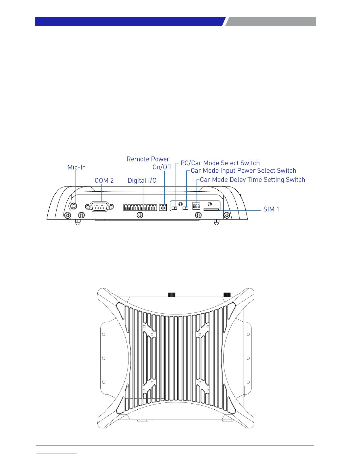
PC300 / PC311E(P) l User’s Manual
12
Chapter 1: Product Introductions
Side (Left)
Mic-in
Used to connect a microphone
COM port
COM2 support RS232/422/485 serial device
Digital I/O Terminal Block
The Digital I/O terminal block supports 4 digital
input and 4 digital output
Remote power on/off switch
Used to plug a power on/off switch with terminal
block
PC/CAR mode select switch
Used to select PC or CAR power mode
12V/24V mode select switch
Used to select Car power input voltage
DELAY TIME switch
Used to select Car power turn off delay-time
SIM card
Used to insert SIM card
Top
VESA Mounting Hole
These are mounting holes for VESA mount (75x75mm and 100x100mm)
Page 13
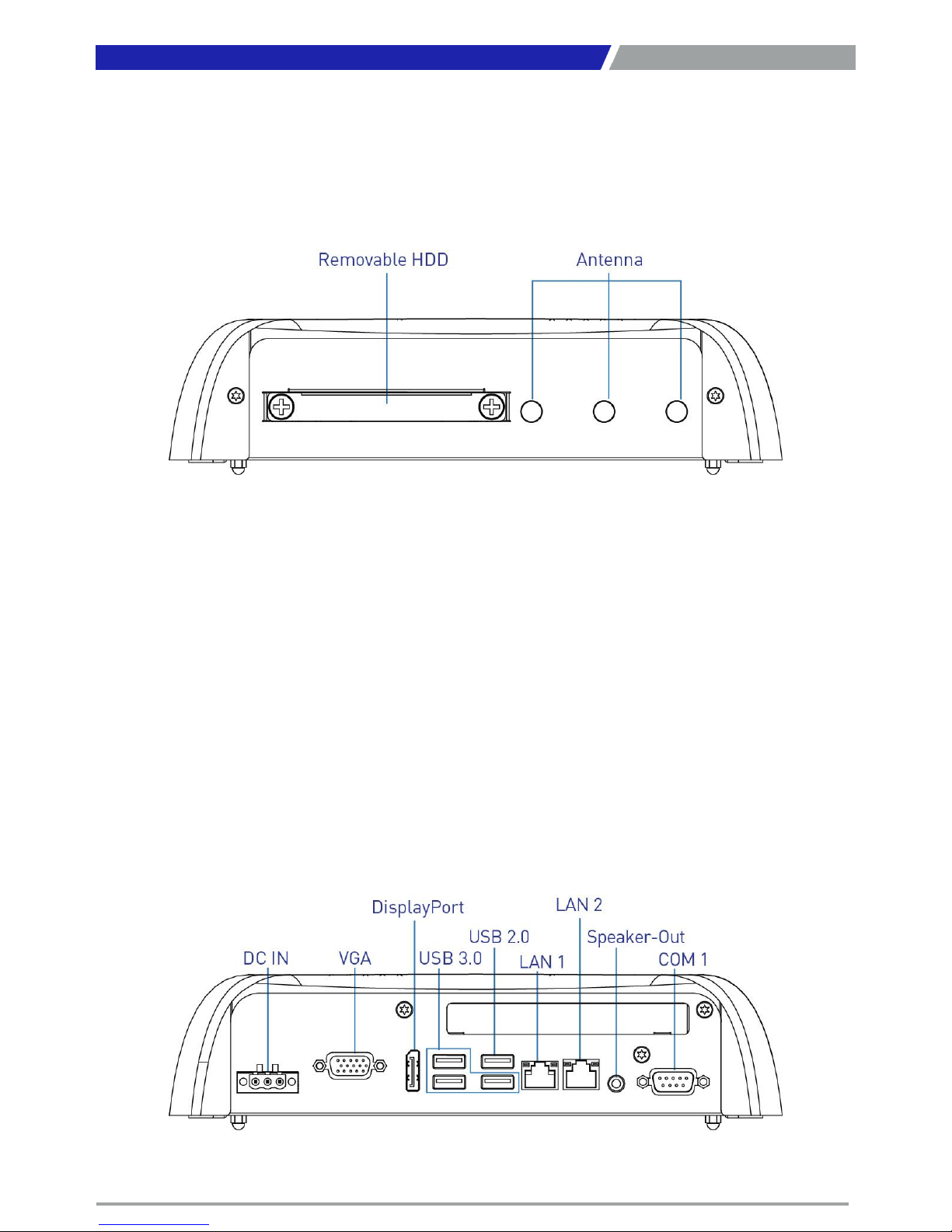
PC300 / PC311E(P) l User’s Manual
13
Chapter 1: Product Introductions
1.3.2 PC311E / PC311P
Front Panel
Removable HDD Bay
Used to inserts a 2.5” HDD device
Antenna hole
Used to connect an antenna for optional MiniPCIe WiFi module
Rear Panel
DC IN
Used to plug a DC power input with terminal
block
VGA
Used to connect an analog VGA monitor
DisplayPort
Used to connect a DisplayPort monitor
USB 3.0 port
Used to connect USB 3.0/2.0/1.1 device
USB 2.0 port
Used to connect USB 2.0/1.1 device
LAN port
Used to connect the system to a local area
network
Speaker-out
Used to connect a external speaker
COM port
COM1 support RS232/422/485 serial device
Expansion Area
Used to plug PCI or PCIe Card
Page 14
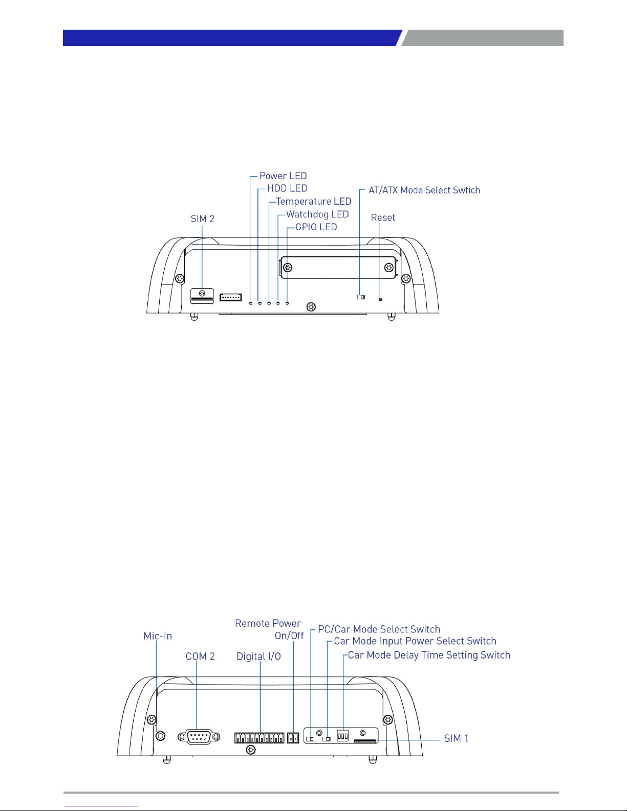
PC300 / PC311E(P) l User’s Manual
14
Chapter 1: Product Introductions
Side (Left)
Mic-in
Used to connect a microphone
COM port
COM2 support RS232/422/485 serial device
Digital I/O Terminal Block
The Digital I/O terminal block supports 4 digital
input and 4 digital output
Remote power on/off switch
Used to plug a power on/off switch with terminal
block
PC/CAR mode select switch
Used to select PC or CAR power mode
12V/24V mode select switch
Used to select Car power input voltage
DELAY TIME switch
Used to select Car power turn off delay-time
SIM card
Used to insert SIM card
Side (Right)
SIM card
Used to insert SIM card
ATX power on/off switch
Press to power-on or power-off the system
Reset switch
Press to reset the system
Universal I/O Bracket
Used to customized I/O output
Page 15
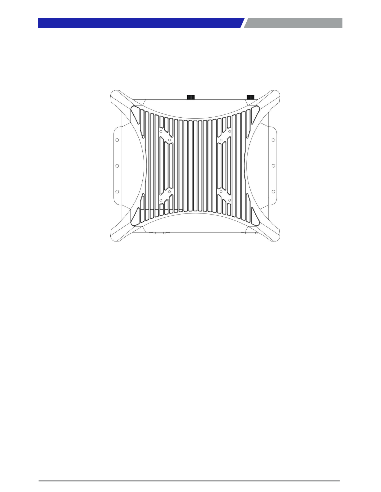
PC300 / PC311E(P) l User’s Manual
15
Chapter 1: Product Introductions
Top
VESA Mounting Hole
These are mounting holes for VESA mount (75x75mm and 100x100mm)
Page 16
PC300 / PC311E(P) l User’s Manual
16
1.4 Mechanical Dimensions
1.4.1 PC300
Unit: mm
Chapter 1: Product Introductions
Page 17
PC300 / PC311E(P) l User’s Manual
17
1.4.2 PC311E / PC311P
Unit: mm
Chapter 1: Product Introductions
Page 18

Chapter 2
Switches and Connectors
Page 19
PC300 / PC311E(P) l User’s Manual
19
2.1 Switch and Connector Locations
2.1.1 Top View
Chapter 2: Switches and Connectors
2.1.2 Bottom View
Page 20
PC300 / PC311E(P) l User’s Manual
20
2.2 Connector / Switch Definition
List of Connector / Switch
Chapter 2: Switches and Connectors
Connector Location Definition
AT_ATX
1
AT
/ ATX Power Mode Switch
CLR_CMOS
1
Clear
BIOS Switch
CAR_PWR
1
PC
/ CAR Power Mode Switch
12
-24V_SEL1
Car
Power input voltage Switch
DELAY_TIME
1
Car power turn off delay
time Switch
PWR_SW
1
Remote
Power Switch
RESET
1
Reset
Switch
USB
1_2_1
USB 3.0 Port
USB
3_4_1
USB 3.0 / USB 2.0 Port
SIM
1, SIM2
SIM
Card Socket
COM1_1
, COM2_1
RS232
/ RS422 / RS485 Connector
COM3_1
, COM4_1
RS232
/ RS422 / RS485 Connector
LAN
1_1, LAN2_1
LAN Port
DC_IN
1
3
-pin DC 9~48V Power Input Connector
VGA1VGA Connector
DP1
DisplayPort
Connector
SPK_OUT
1
Speaker
-out Jack
MIC_IN
1
Mic
-in Jack
DIO1
4DI
/ 4DO Connector
CN
1, CN2
Mini PCI
-Express / mSATA Socket
SATA
1
SATA
with Power Connector
SATA
2
SATA Connector
POWER1, POWER2, POWER3
Power Connector
PCIE1
PCI
-Express X4 Slot
PWR_LED
1
Power LED Status
HDD_LED
1
HDD Access LED Status
TEMP_LED
1
Temperature LED Status
WDT_LED
1
Watchdog LED Status
GPIO_LED
1
GPIO LED Status
Page 21
PC300 / PC311E(P) l User’s Manual
21
Switch Definition
1-2 (Left)
AT Power Mode
2-3 (Right)
ATX Power Mode
(Default)
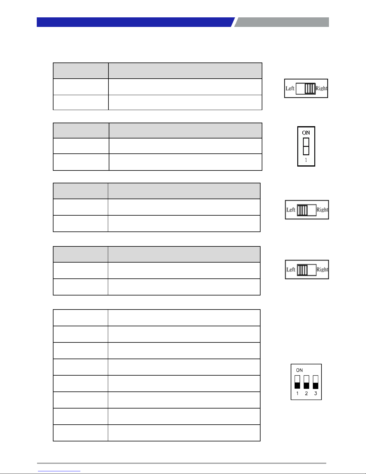
2.3 Switches Definitions
AT_ATX1: AT / ATX Power Mode Switch
CLR_CMOS1: Clear BIOS Switch
Switch Definition
Off Normal Status (Default)
ON Clear BIOS
CAR_PWR1: PC / CAR Power Mode Switch
Chapter 2: Switches and Connectors
Switch Definition
1-2 (Left)
PC Power Mode
(Default)
2-3 (Right)
CAR Power Mode
12-24V_SEL1 : Car Power input voltage Switch
Switch Definition
1-2 (Left)
DC
24V CAR Power Input Mode(Default)
2-3 (Right)
DC
12V CAR Power Input Mode
DELAY_TIME1 : Car power turn off delay time Switch
Switch 1 / 2 / 3 Definition
OFF / OFF / OFF
0 sec.
(Default)
ON / ON / OFF
1 min.
ON / OFF / ON
5 min.
ON / OFF / OFF
10 min.
OFF / ON / ON
30 min.
OFF / ON / OFF
1 hour
OFF / OFF / ON
2 hour
Page 22
PC300 / PC311E(P) l User’s Manual
22
Chapter 2: Switches and Connectors
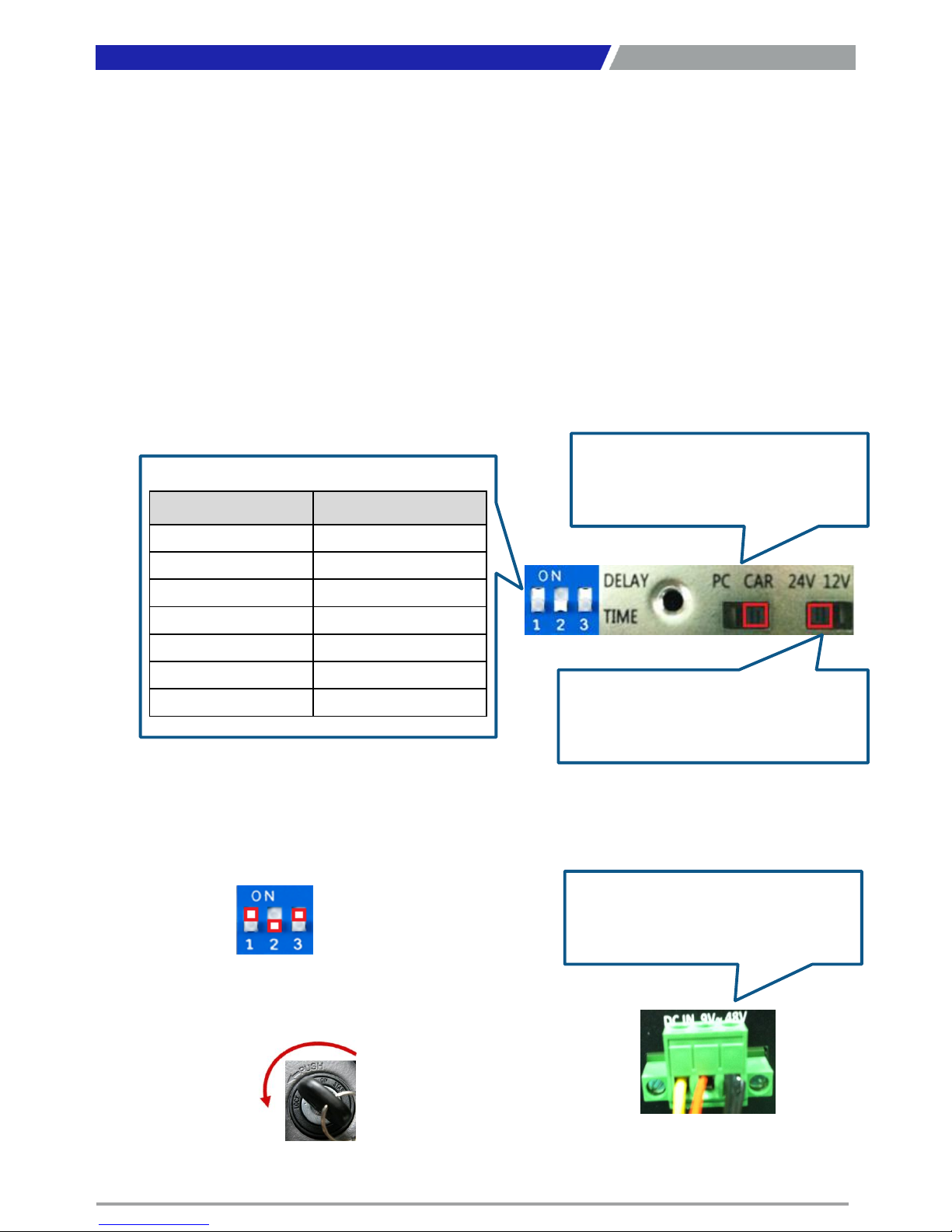
Step 1:
To select power ignition by PC/CAR switch.
Step 2:
To select battery input voltage by 12V / 24V switch.
Step 3:
To configure the power off delay time, please check the Delay Time Setting Options in advance.
Step 4:
To connect the power and ignition power
Example: Delay Time Setting for 5 minutes
1. If delay time set as “5 minutes”
2. The system will shut down 5 minutes later after
turning off the vehicle.
Step 1
Pin 1-2 (Left): PC Power Mode
Pin 2-3 (Right): Power Ignition Mode
Step 2
Pin 1-2 (Left): Battery 24V Input Mode
Pin 2-3 (Right): Battery 12V Input Mode
Switch 1 / 2 / 3 Power off delay time
ON / ON / ON
0 second
ON / ON / OFF
1 minute
ON / OFF / ON
5 minutes
ON / OFF / OFF
10 minutes
OFF / ON / ON
30 minutes
OFF / ON / OFF
1 hour
OFF / OFF / ON
2 hours
Step 3
Step 4
To connect the battery power and
ignition power
Page 23
PC300 / PC311E(P) l User’s Manual
23
2.4 Connectors Definitions
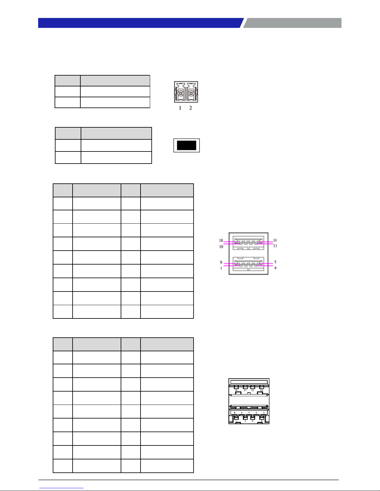
PWR_SW1 : Remote Power Switch
Connector Type: Terminal Block 1X2 2-pin, 3.5mm pitch
Chapter 2: Switches and Connectors
Pin Definition
1 Power Button
2 GND
RESET1 : Reset Button
Pin Definition
1 RESET
2 GND
USB1_2_1: USB3.0 Connector, Type A
Pin Definition Pin Definition
1 +5V 10 +5V
2 USB2_D0- 11 USB2_D1-
3 USB2_D0+ 12 USB2_D1+
4 GND 13 GND
5 USB3_RX1- 14 USB3_RX2-
6 USB3_RX1+ 15 USB3_RX2+
7 GND 16 GND
8 USB3_TX1- 17 USB3_TX2-
9 USB3_TX1+ 18 USB3_TX2+
USB3_4_1: USB3.0 / USB2.0 Connector, Type A
Pin Definition Pin Definition
1 +5V 10 +5V
2 USB2_D2- 11 USB2_D3-
3 USB2_D2+ 12 USB2_D3+
4 GND 13 GND
5 USB3_R3- 14
6 USB3_R3+ 15
7 GND 16
8 USB3_TX3- 17
9 USB3_TX3+ 18
Page 24
PC300 / PC311E(P) l User’s Manual
24
Chapter 2: Switches and Connectors
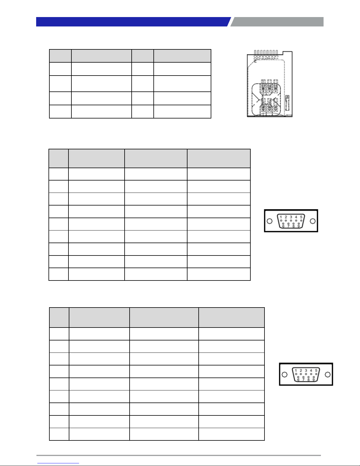
SIM1, SIM2:SIM Card Socket
Pin Definition Pin Definition
C1 UIM_PWR C6 UIM_VPP
C2 UIM_RESET C7 UIM_DATA
C3 UIM_CLK CD NC
C5 GND COM GND
COM1_1: RS232 / RS422 / RS485 Connector
Connector Type: 9-pin D-Sub
Pin RS232 Definition
RS422 / 485 Full
Duplex Definition
RS485 Half Duplex
Definition
1 DCD1 TX1- DATA1-
2 RxD1 TX1+ DATA1+
3 TxD1 RX1+
4 DTR1 RX1-
5 GND
6 DSR1
7 RTS1
8 CTS1
9 RI1
Pin RS232 Definition
RS422 / 485 Full
Duplex Definition
RS485 Half Duplex
Definition
1 DCD2 TX2- DATA2-
2 RxD2 TX2+ DATA2+
3 TxD2 RX2+
4 DTR2 RX2-
5 GND
6 DSR2
7 RTS2
8 CTS2
9 RI2
COM2_1: RS232 / RS422 / RS485 Connector
Connector Type: 9-pin D-Sub
Page 25
PC300 / PC311E(P) l User’s Manual
25
Chapter 2: Switches and Connectors
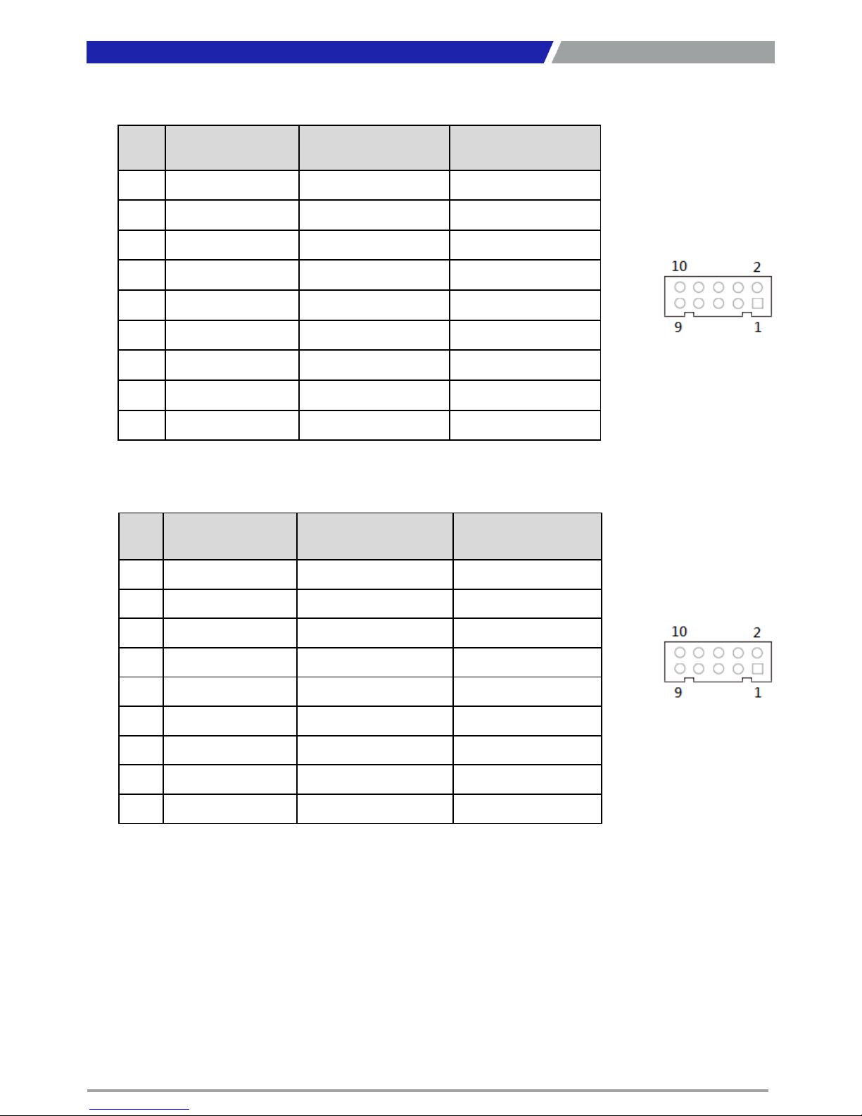
COM3_1: RS232 / RS422 / RS485 Connector
Connector Type: 9-pin D-Sub
Pin RS232 Definition
RS422 / 485 Full
Duplex Definition
RS485 Half Duplex
Definition
1 DCD3 TX3- DATA3-
2 RxD3 TX3+ DATA3+
3 TxD3 RX3+
4 DTR3 RX3-
5 GN3
6 DSR3
7 RTS3
8 CTS3
9 RI3
Pin RS232 Definition
RS422 / 485 Full
Duplex Definition
RS485 Half Duplex
Definition
1 DCD3 TX3- DATA3-
2 RxD3 TX3+ DATA3+
3 TxD3 RX3+
4 DTR3 RX3-
5 GN3
6 DSR3
7 RTS3
8 CTS3
9 RI3
COM4_1: RS232 / RS422 / RS485 Connector
Connector Type: 9-pin D-Sub
Page 26
PC300 / PC311E(P) l User’s Manual
26
Chapter 2: Switches and Connectors
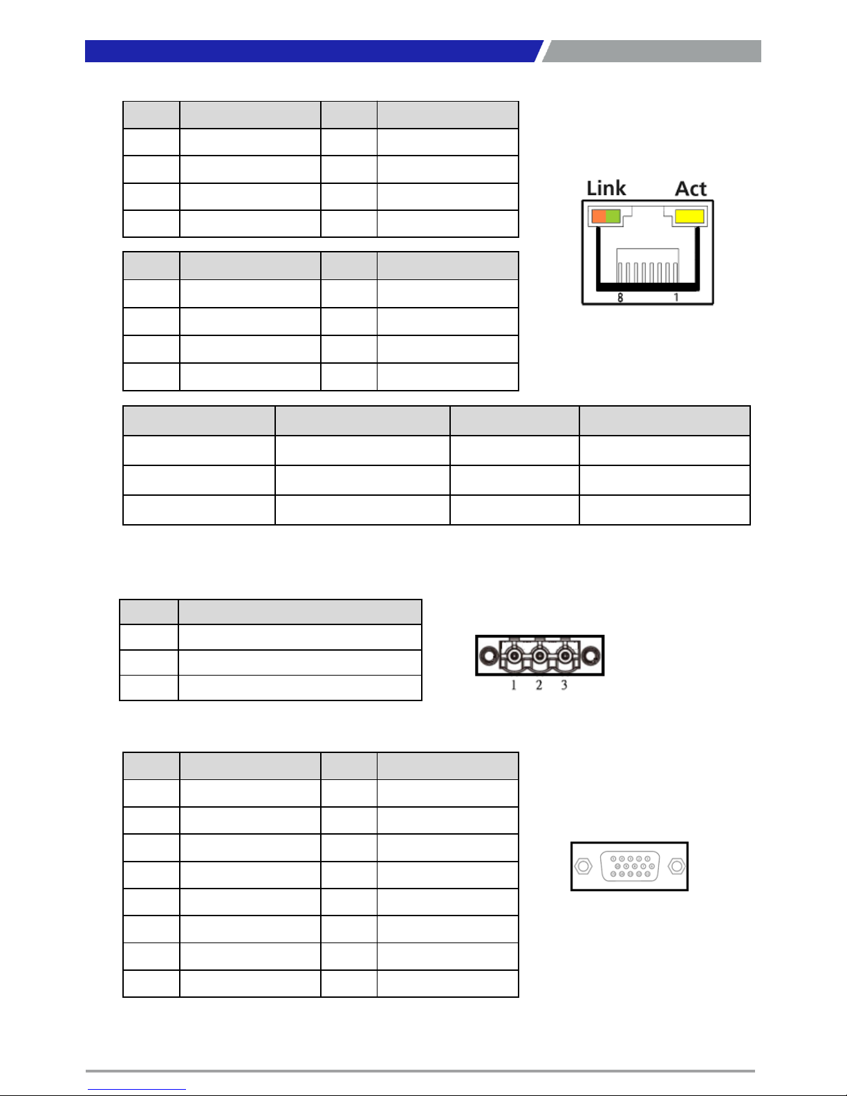
LAN1, LAN2: RJ45 with LEDs Port
Pin Definition Pin Definition
1 LAN1_MDI0P 5 LAN1_MDI2N
2 LAN1_MDI0N 6 LAN1_MDI1N
3 LAN1_MDI1P 7 LAN1_MDI3P
4 LAN1_MDI2P 8 LAN1_MDI3N
Pin Definition Pin Definition
1 LAN2_MDI0P 5 LAN2_MDI2N
2 LAN2_MDI0N 6 LAN2_MDI1N
3 LAN2_MDI1P 7 LAN2_MDI3P
4 LAN2_MDI2P 8 LAN2_MDI3N
Link LED Status Definition Act LED Status Definition
Steady Orange 1Gbps Network Link Blinking Yellow Data Activity
Steady Green 100Mbps Network Link Off No Activity
Off 10Mbps Network Link
DC_IN1: DC Power Input Connector (+9~48V)
Connector Type: Terminal Block 1X3 3-pin, 5.0mm pitch
Pin Definition
1 +9~48VIN
2 Power Ignition
3 GND
VGA1: VGA Connector
Pin Definition Pin Definition
1 RED 9 +5V
2 GREEN 10 GND
3 BLUE 11 NC
4 NC 12 DDC_SDA
5 GND 13 HSYNC
6 RED_GND 14 VSYNC
7 GREEN_GND 15 DDC_SCL
8 BLUE_GND
Page 27
PC300 / PC311E(P) l User’s Manual
27
Chapter 2: Switches and Connectors
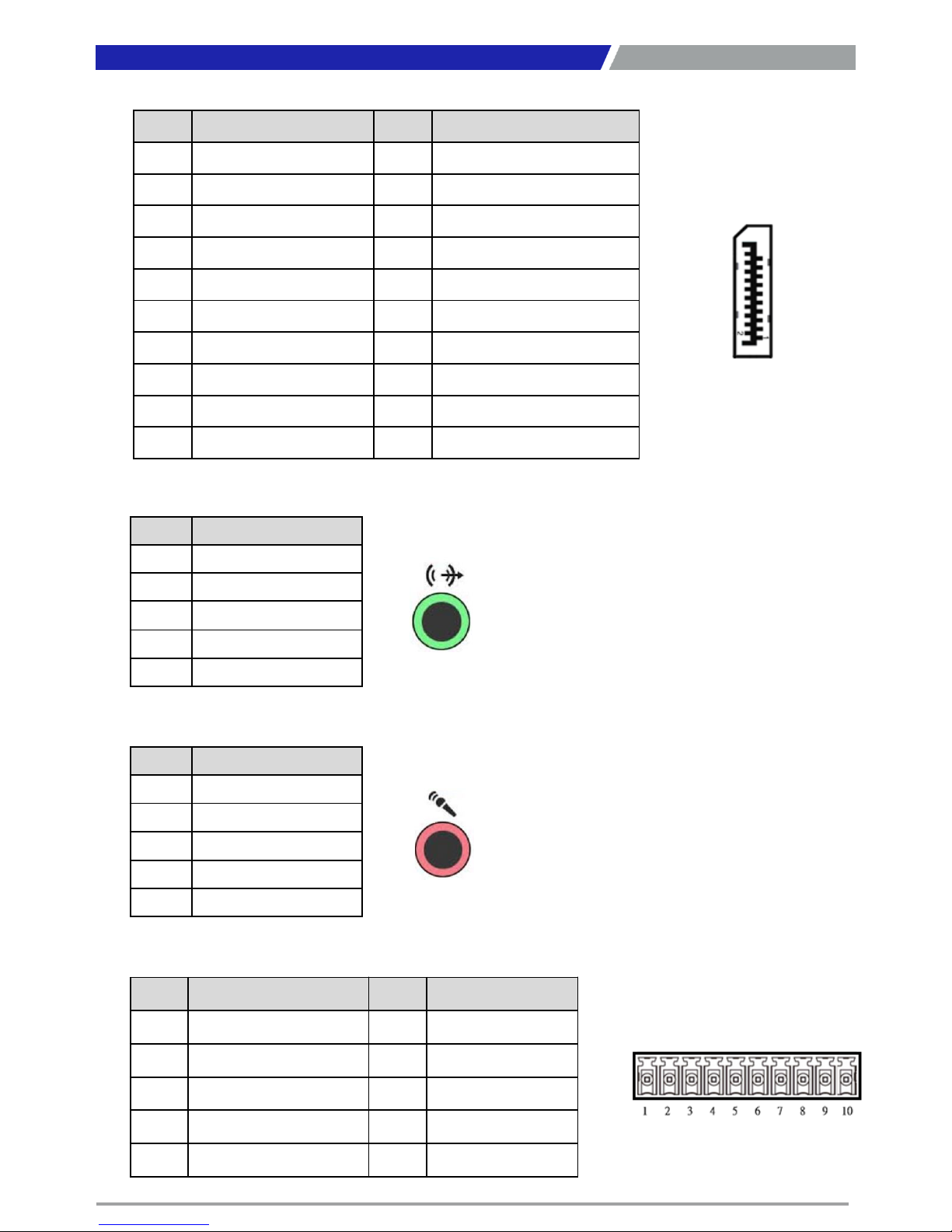
DP1: DisplayPort Connector
Pin Definition Pin Definition
1 DP_LANE0_P 11 GND
2 GND 12 DP_LANE3_N
3 DP_LANE0_N 13 GND
4 DP_LANE1_P 14 GND
5 GND 15 DP_AUX_P
6 DP_LANE1_N 16 GND
7 DP_LANE2_P 17 DP_AUX_N
8 GND 18 DP_HPD
9 DP_LANE2_N 19 GND
10 DP_LANE3_P 20 DP_PWR
SPK_OUT1 : Speaker-out Jack (Green)
Connector Type: 5-pin Phone Jack
Pin Definition
1 GND
2 OUT_R
3 NC
4 GND
5 OUT_L
MIC_IN1: Microphone Jack (Pink)
Connector Type: 5-pin Phone Jack
Pin Definition
1 GND
2 MIC_R
3 NC
4 GND
5 MIC_L
DIO1: Digital Input / Output Connector
Connector Type: Terminal Block 1X10 10-pin, 3.5mm pitch
Pin Definition Pin Definition
1 DC INPUT 6 DO1
2 DI1 7 DO2
3 DI2 8 DO3
4 DI3 9 DO4
5 DI4 10 GND
Page 28
PC300 / PC311E(P) l User’s Manual
28
Chapter 2: Switches and Connectors
Page 29
PC300 / PC311E(P) l User’s Manual
Pin
Definition
Pin
Definition
Pin
Definition
1 WAKE# 19 NC 37 GND
2 +3.3V 20 +3.3V 38 USB_D5+
3 NC 21 GND 39 +3.3V
4 GND 22 MINIPCIE RST# 40 GND
5 NC 23
MINIPCIE_RXN2
(SATA_RXP2)
41 +3.3V
6 +1.5V 24 +3.3V 42 NC
7 CLKREQ5# 25
MINIPCIE_RXP2
(SATA_RXN2)
43 GND
8 USIM1_PWR 26 GND 44 NC
9 GND 27 GND 45 NC
10 USIM1_DATA 28 +1.5V 46 NC
11 MINIPCIE_CLKN2 29 GND 47 NC
12 USIM1_CLK 30 SMB_CLK 48 +1.5V
13 MINIPCIE_CLKP2 31
MINIPCIE_TXN2
(SATA_TXP2)
49 NC
14 USIM1_RESET 32 SMB_DATA 50 GND
15 GND 33
MINIPCIE_TXP2
(SATA_TXN2)
51 NC
16 USIM1_VPP 34 GND 52 +3.3V
17 NC 35 GND
18 GND 36 USB_D5-
29
Chapter 2: Switches and Connectors
29
Chapter 2: Switches and Connectors
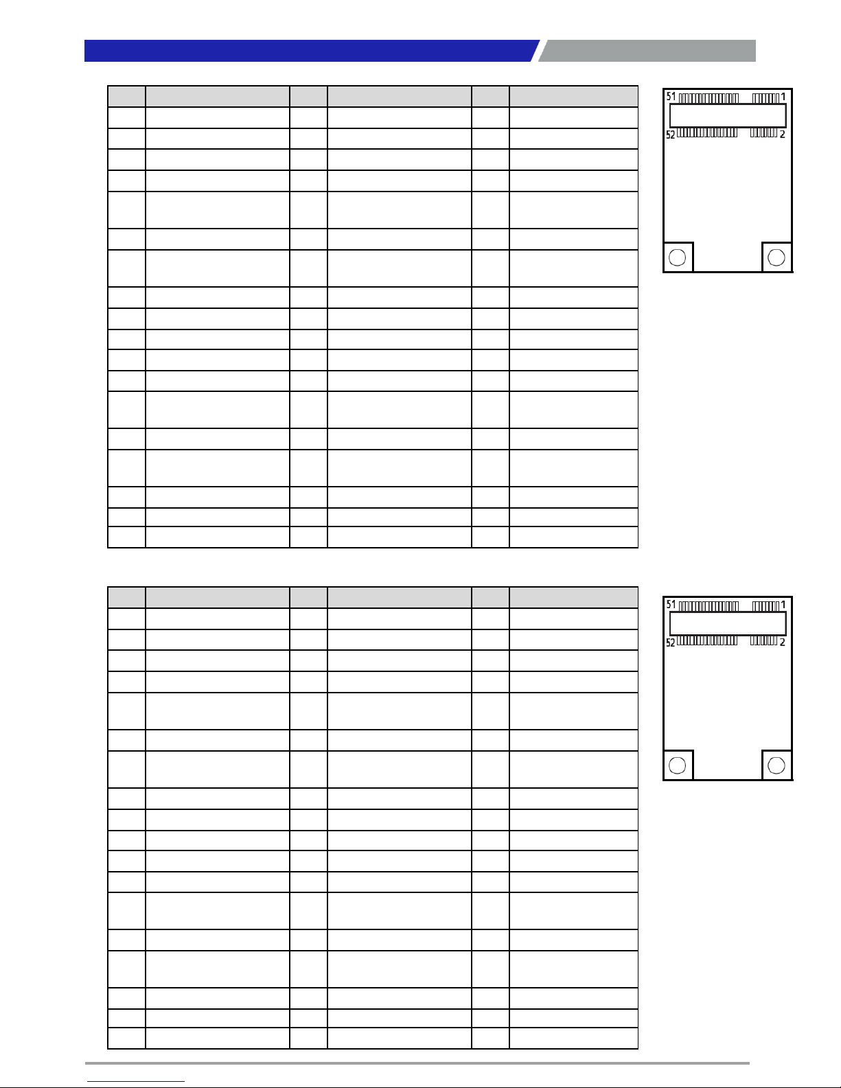
CN1: Mini PCI-Express / mSATA Socket
CN2: Mini PCI-Express / mSATA Socket
Pin
Definition
Pin
Definition
Pin
Definition
1 WAKE# 19 NC 37 GND
2 +3.3V 20 +3.3V 38 USB_D4+
3 NC 21 GND 39 +3.3V
4 GND 22 MINIPCIE RST# 40 GND
5 NC 23
MINIPCIE_RXN6_0
(SATA_RXN3)
41 +3.3V
6 +1.5V 24 +3.3V 42 NC
7 CLKREQ4# 25
MINIPCIE_RXP6_0
(SATA_RXP3)
43 GND
8 USIM2_PWR 26 GND 44 NC
9 GND 27 GND 45 NC
10 USIM2_DATA 28 +1.5V 46 NC
11 MINIPCIE_CLKN1 29 GND 47 NC
12 USIM2_CLK 30 SMB_CLK 48 +1.5V
13 MINIPCIE_CLKP1 31
MINIPCIE_TXN6_0
(SATA_TXN3)
49 NC
14 USIM2_RESET 32 SMB_DATA 50 GND
15 GND 33
MINIPCIE_TXP6_0
(SATA_TXP3)
51 NC
16 USIM2_VPP 34 GND 52 +3.3V
17 NC 35 GND
18 GND 36 USB_D4-
Page 30
PC300 / PC311E(P) l User’s Manual
30
Chapter 2: Switches and Connectors
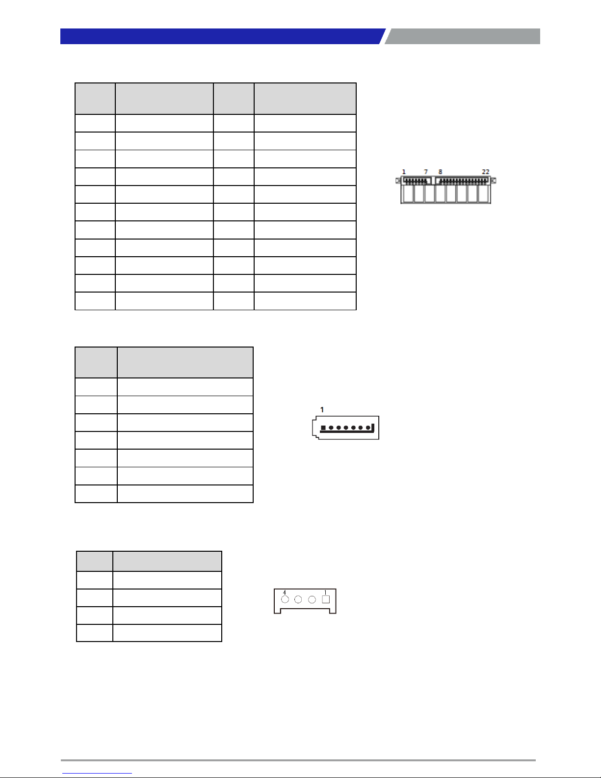
SATA1: SATA with Power Connector
Pin Definition Pin Definition
1 GND 12 GND
2 SATA_TXP0 13 GND
3 SATA_TXN0 14 +5V
4 GND 15 +5V
5 SATA_RXN0 16 +5V
6 SATA_RXP0 17 GND
7 GND 18 GND
8 +3.3V 19 GND
9 +3.3V 20 +12V
10 +3.3V 21 +12V
11 GND 22 +12V
SATA2: SATA Connector
Pin Definition
1 GND
2 SATA_TXP0
3 SATA_TXN0
4 GND
5 SATA_RXN0
6 SATA_RXP0
7 GND
POWER1, POWER2, POWER3: Power Connector
Connector Type: 1X4-pin Wafer, 2.0mm pitch
Pin Definition
1 +5V
2 GND
3 GND
4 +12V
Page 31
PC300 / PC311E(P) l User’s Manual
31
Chapter 2: Switches and Connectors
Pin Definition Pin Definition Pin Definition Pin Definition
A1
PCIE_PRSNT1
A17 PEG_RXN0 B1 +12V B17 PRSNT2_1
A2 +12V A18 GND B2 +12V B18 GND
A3 +12V A19 NC B3 +12V B19 PEG_TXP1
A4 GND A20 GND B4 GND B20 PEG_TXN1
A5 NC A21 PEG_RXP1 B5 SMB_CLK B21 GND
A6 NC A22 PEG_RXN1 B6 SMB_DATA B22 GND
A7 NC A23 GND B7 GND B23 PEG_TXP2
A8 NC A24 GND B8 +3.3V B24 PEG_TXN2
A9 +3.3V A25 PEG_RXP2 B9 NC B25 GND
A10
+3.3V A26 PEG_RXN2 B10 +3.3VSB B26 GND
A11
PCIE_RESET# A27 GND B11 PCIE_WAKE# B27 PEG_TXP3
A12
GND A28 GND B12 NC B28 PEG_TXN3
A13
PEG_CLK_P A29 PEG_RXP3 B13 GND B29 GND
A14
PEG_CLK_N A30 PEG_RXN3 B14 PEG_TXP0 B30 NC
A15
GND A31 GND B15 PEG_TXN0 B31 PRSNT2_2
A16
PEG_RXP0 A32 NC B16 GND B32 GND
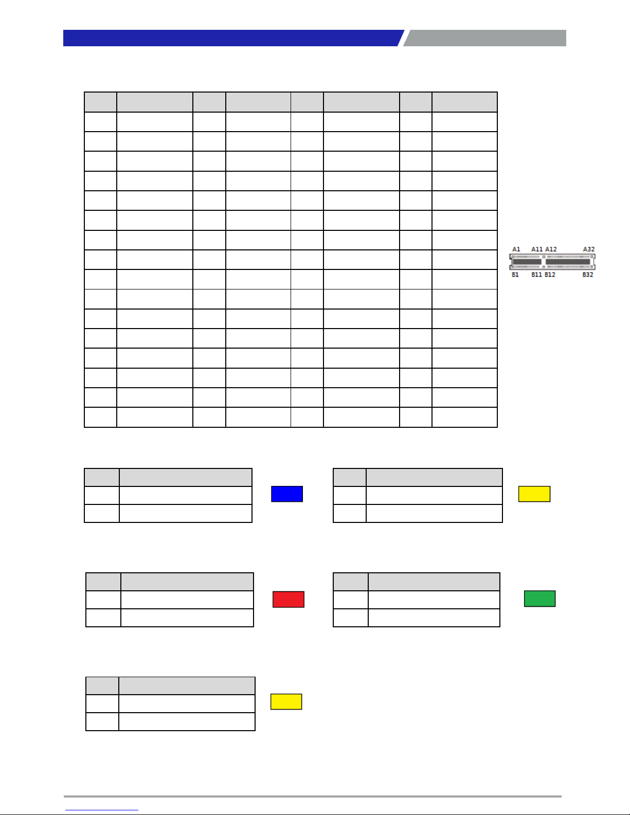
PCIE1: PCI-Express X4 Socket
Connector Type: PCI-Express X4 Slot
PWR_LED1: Power LED Status
Pin Definition
1 POWER LED+
2 POWER LED-
Pin Definition
1 HDD LED+
2 HDD LED-
HDD_LED1: HDD Access LED Status
TEMP_LED1: Temperature LED Status
Pin Definition
1 TEMPERATURE LED+
2 TEMPERATURE LED-
Pin Definition
1 WATCHDOG LED+
2 WATCHDOG LED-
WDT_LED1: Watchdog LED Status
Pin Definition
1 GPIO LED+
2 GPIO LED-
GPIO_LED1: GPIO LED Status
Page 32

Chapter 3
System Setup
Page 33
PC300 / PC311E(P) l User’s Manual
3.1 Set torque force to 3.5 kgf-cm to execute all the screwing and
unscrewing.
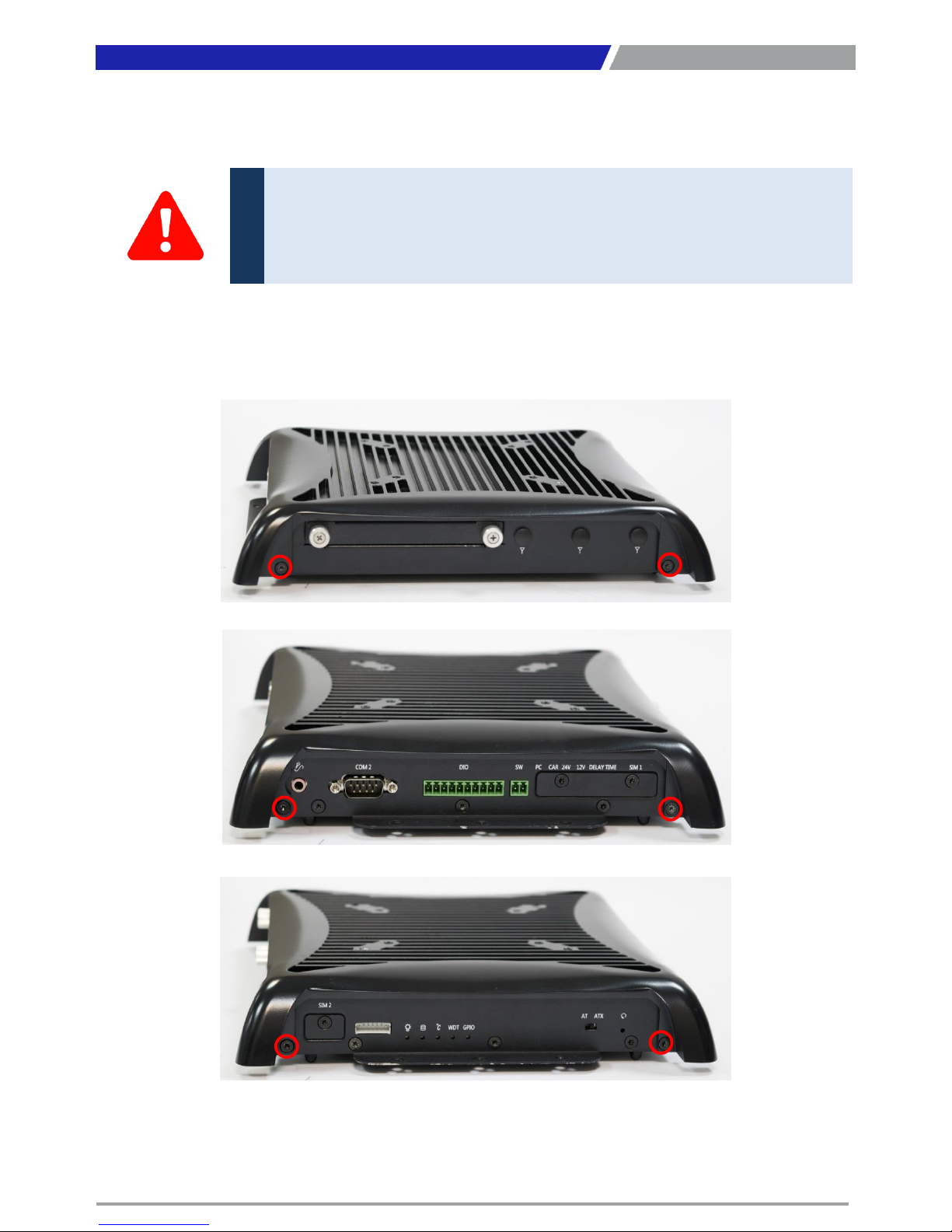
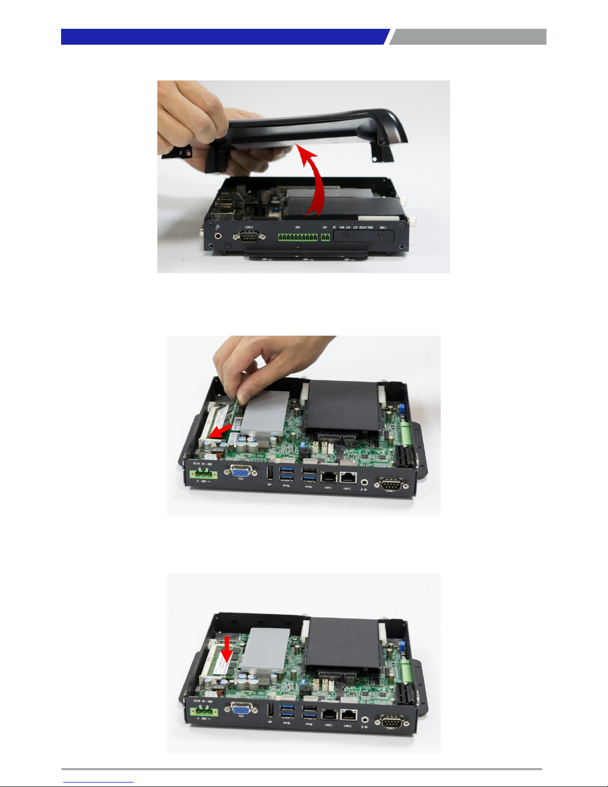
3.2 Removing chassis top cover.
1. Unscrew the 6 screws (M3x5L) below.
33
Chapter 3: System Setup
In order to prevent electric shock or system damage, before removing the
chassis cover, must turn off power and disconnect the unit from power source.
WARNING
Page 34
PC300 / PC311E(P) l User’s Manual
2. Now you can remove the top cover of PC module.
3.3 Installing SODIMM
1. Insert memory module from 45 degree direction.
2. Press the memory module vertically downward until you hear the “click” sound. Make sure the
memory module is firmly in place.
34
Chapter 3: System Setup
Page 35
PC300 / PC311E(P) l User’s Manual
35
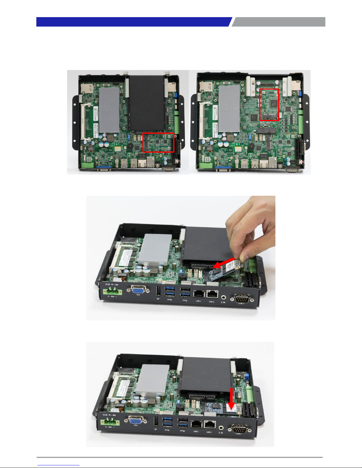
3.4 Installing mini PCIe card / mSATA
1. Two mini PCIe slots are available for PC300 series; the second one can be seen when the
HDD bay is removed. They both also support mSATA.
2. Insert mini PCIe card or mSATA module from 45 degree direction.
3. Press the mini PCIe card or mSATA module down and lock it with two screws (M2x3.7L).
Chapter 3: System Setup
Page 36
PC300 / PC311E(P) l User’s Manual
36
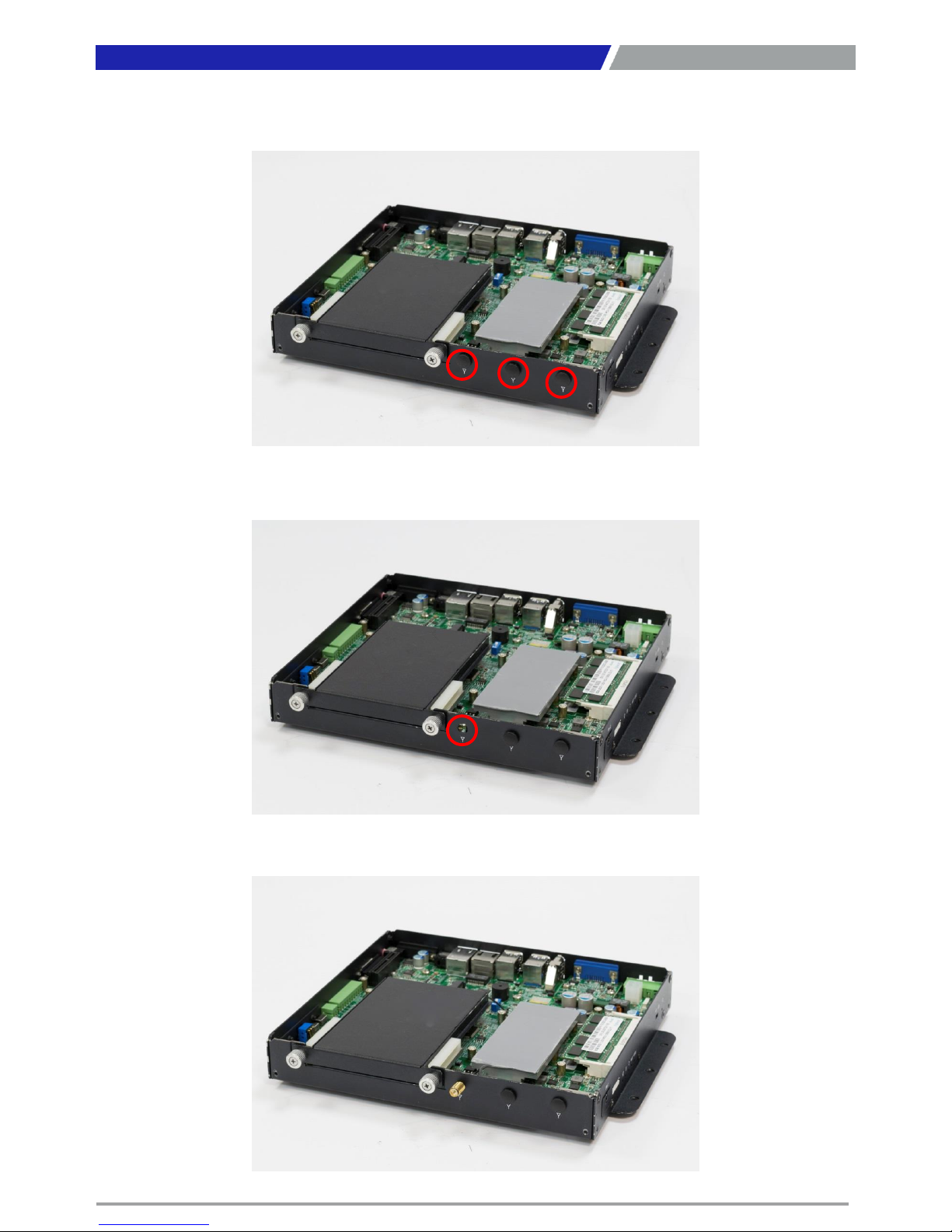
3.5 Installing antenna
1. Three antenna holes are available for PC300 series.
2. Remove antenna hole cover on the system panel.
3. Have antenna jack penetrate through the hole.
Chapter 3: System Setup
Page 37
PC300 / PC311E(P) l User’s Manual
37
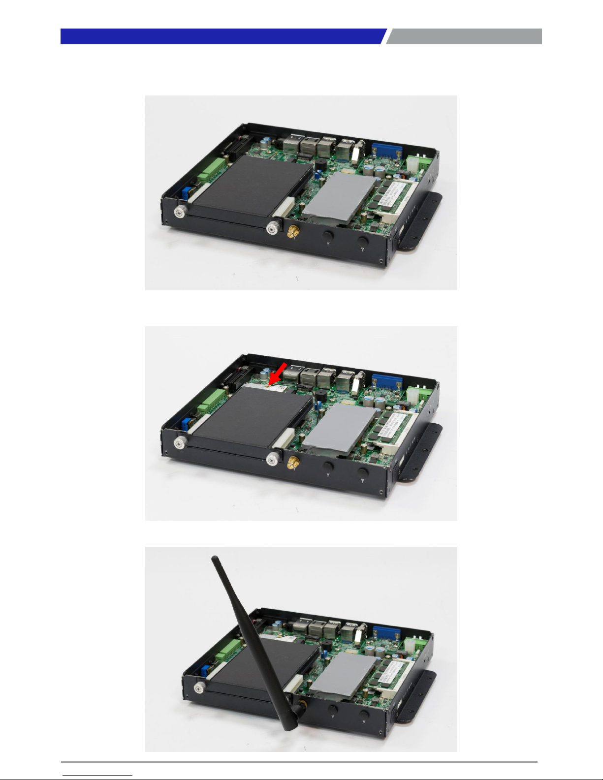
4. Put on washer and fasten the nut with antenna jack.
5. Attach the RF connector at the cable-end onto the communication module.
6. Assemble the antenna and antenna jack together.
Chapter 3: System Setup
Page 38
PC300 / PC311E(P) l User’s Manual
38
3.6 Installing PCIe/PCI expansion card (Only for PC311E & PC311P)
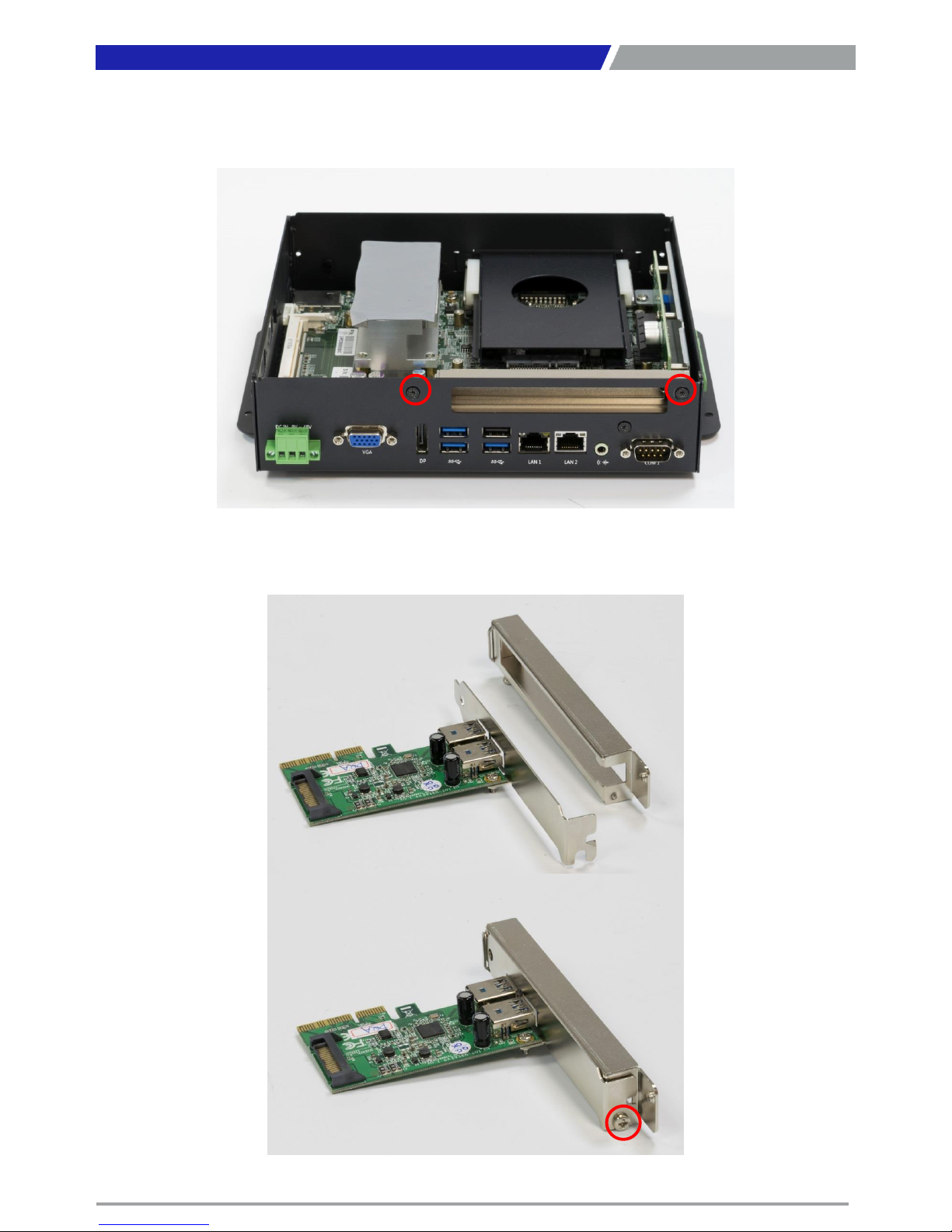
1. PCIe or PCI card with FHHL dimension is supported by PC311 series.
2. Unscrew the two screws (M3x5L) to remove the expansion window bracket.
3. Lock your expansion card with the expansion window bracket by one screw (M3x5L).
Chapter 3: System Setup
Page 39
PC300 / PC311E(P) l User’s Manual
39
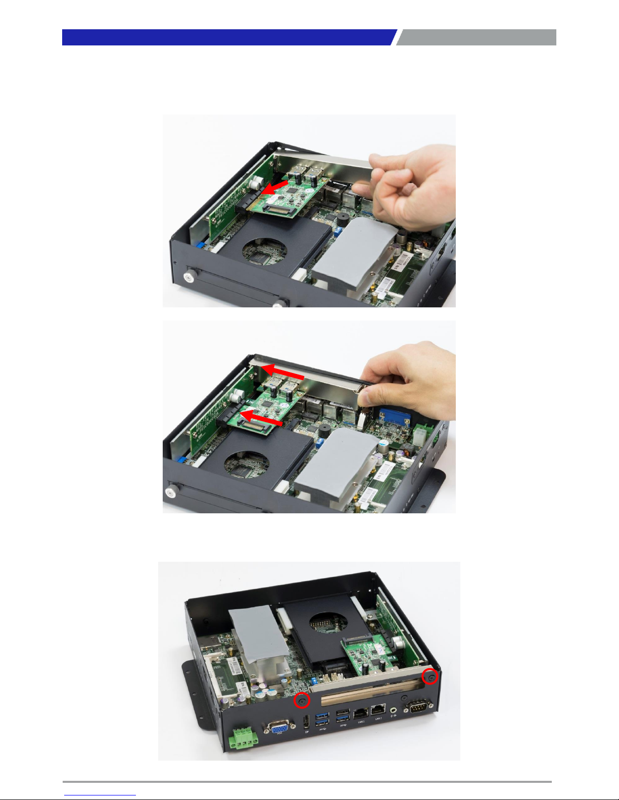
4. Install the PCIe/PCI card according to the below direction and then push the card towards the
slot to ensure the gold finger is firmly inserted into the slot.
5. Fasten the two screws (M3x5L) on the panel back to lock the card and expansion window
bracket.
Chapter 3: System Setup
Page 40
PC300 / PC311E(P) l User’s Manual
40
3.7 Assembly chassis top cover
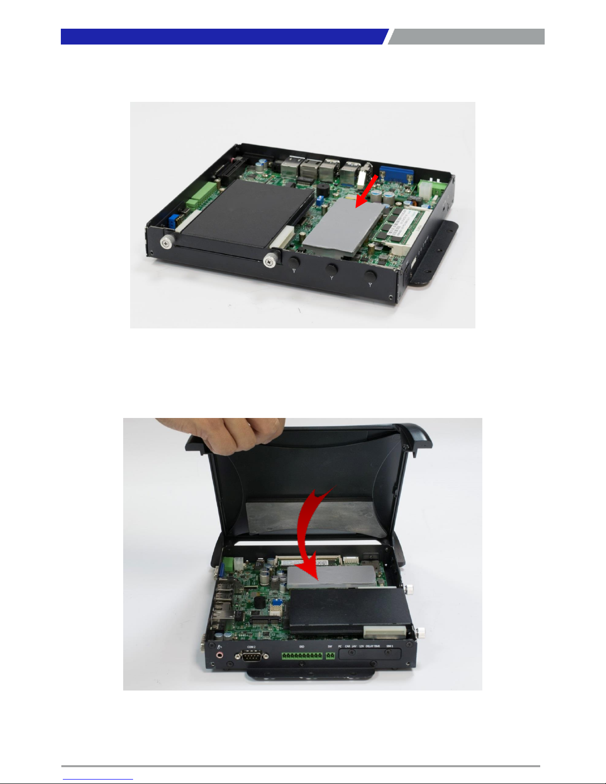
1. Ensure thermal pad is in place on the CPU thermal block.
2. Close the chassis top cover following the below direction and make sure the aluminum part
on the top cover is touching the thermal pad on CPU thermal block.
Chapter 3: System Setup
Page 41
PC300 / PC311E(P) l User’s Manual
41
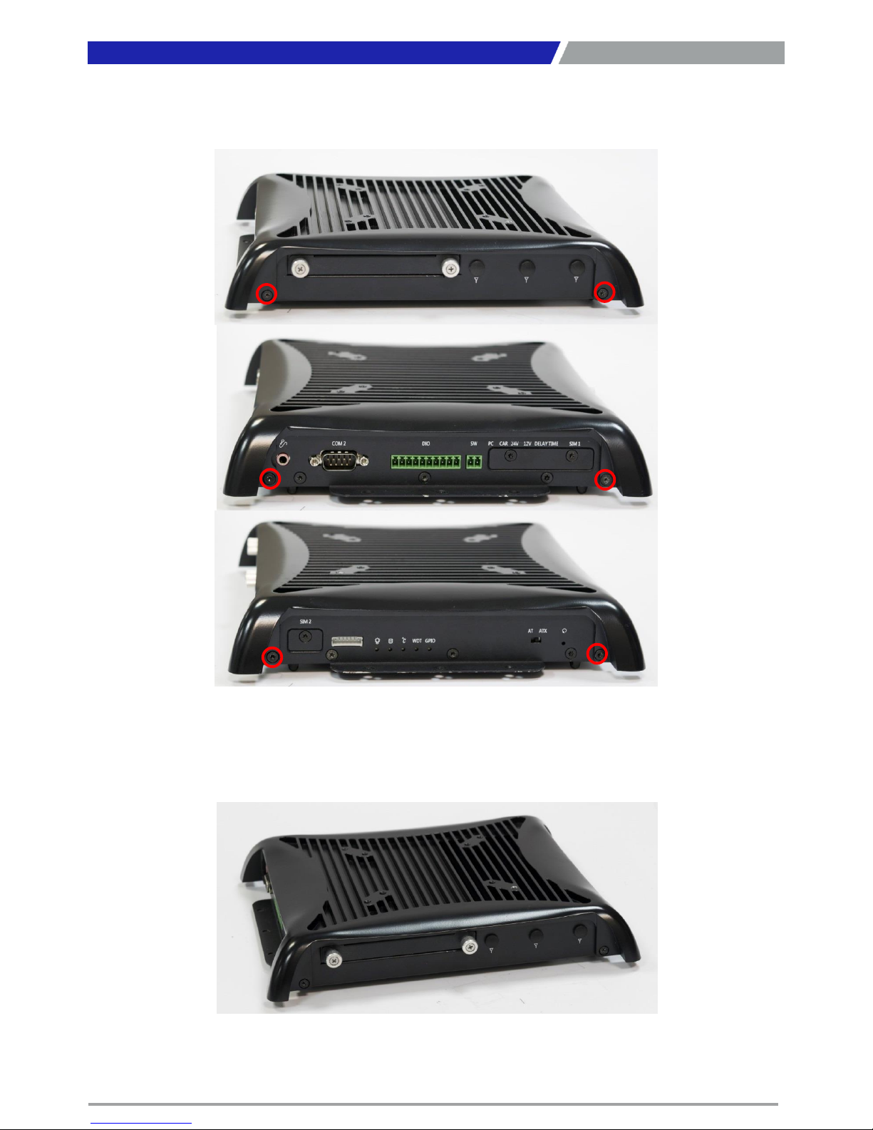
3. Fasten the six screws (M3x5L) to lock the system body with top cover.
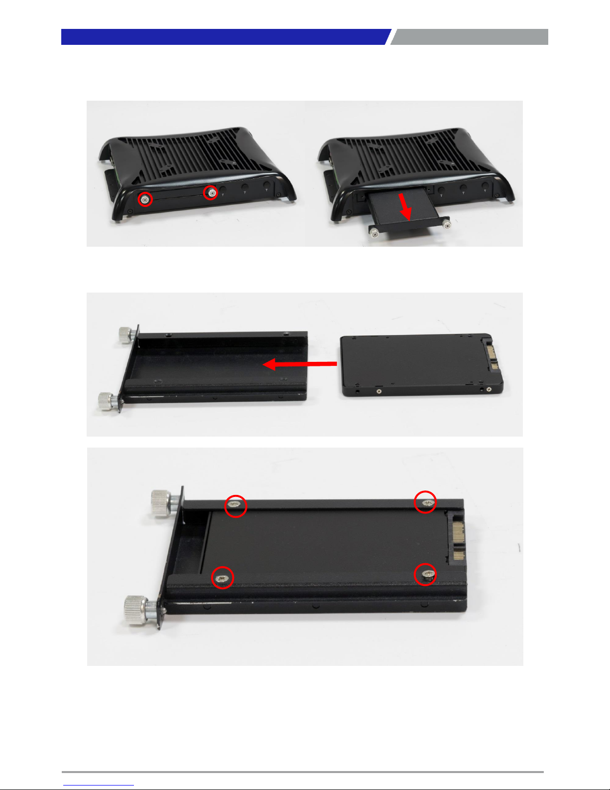
3.8 Installing HDD on removable SATA HDD bay
1. One removable SATA HDD bays are available for PC300 Series.
Chapter 3: System Setup
Page 42
PC300 / PC311E(P) l User’s Manual
42
2. Unscrew the two sun screws circled below to take out the removable SATA HDD bay.
3. Lock the 2.5” HDD with HDD bracket using four screws (M3x4L).
Chapter 3: System Setup
Page 43
PC300 / PC311E(P) l User’s Manual
43
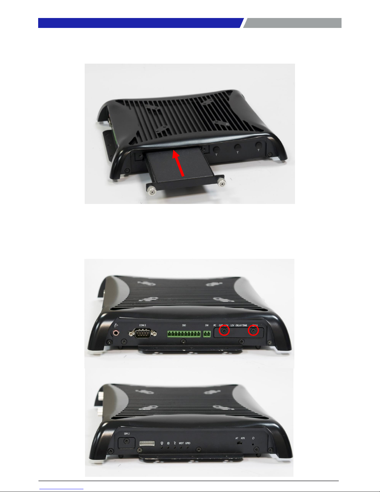
4. Slide the HDD bracket back and then fasten the sun screws.
3.9 Installing SIM card
1. For PC300 Series, SIM card slots are located on the side of the system inside protective
bracket. Unscrew the screws (M3x5L) below to remove the bracket.
Chapter 3: System Setup
Page 44
PC300 / PC311E(P) l User’s Manual
44
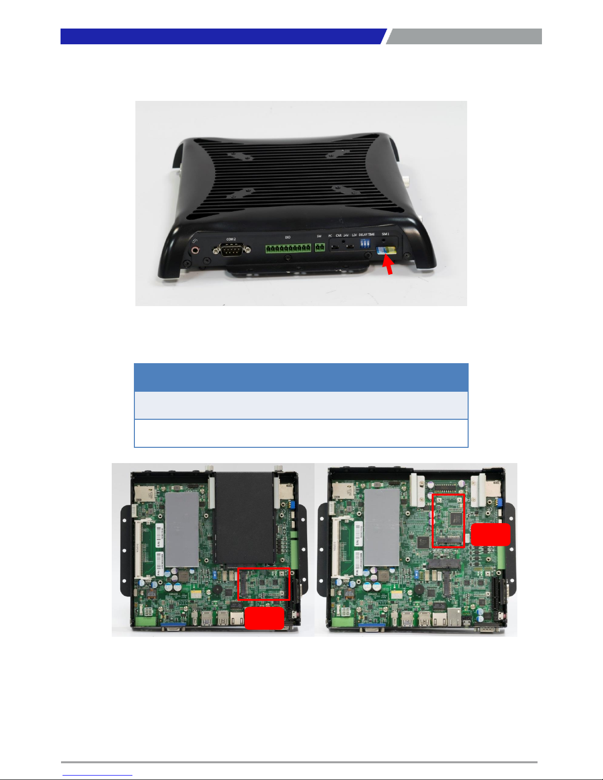
2. Now you can insert SIM card into the socket.
3. Please note that the installation of SIM 1 and SIM 2 has to match the installation of mini PCIe
slots.
4. To uninstall SIM card, simply press the installed SIM card and then the card will be pushed out.
Chapter 3: System Setup
SIM Card Socket Number
Matching Mini PCIe Slot
SIM 1
Mini
PCIe / mSATA (CN2)
SIM 2
Mini
PCIe / mSATA (CN1)
CN1
CN2
Page 45
PC300 / PC311E(P) l User’s Manual
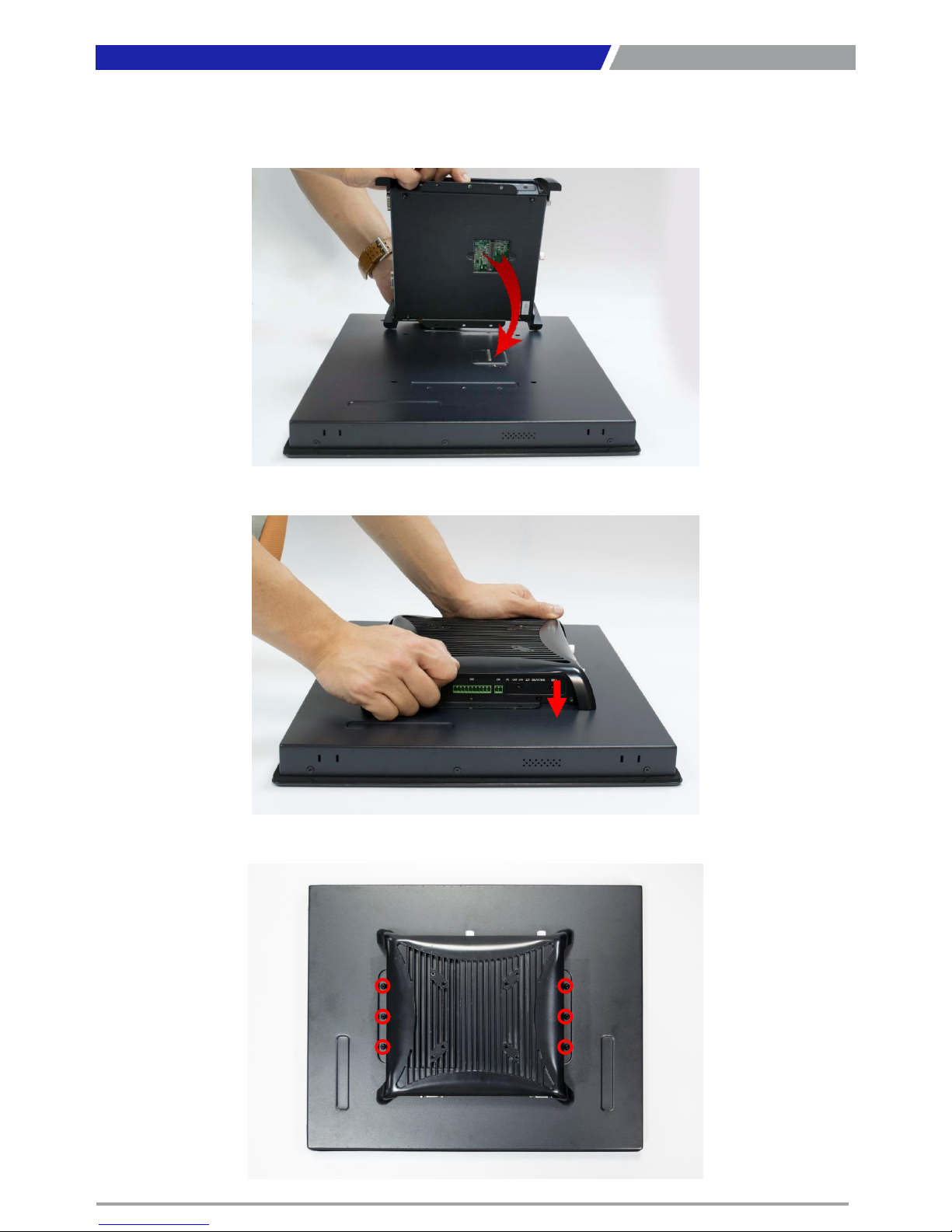
4.10 Connecting PC module with VIO display module
1. Hold the PC module with its connector facing towards the connector on the back of VIO
display module.
2. Press the PC module downward to ensure two modules are firmly connected.
3. Lock the below 6 screws (M4x5L).
45
Chapter 3: System Setup
Page 46
PC300 / PC311E(P) l User’s Manual
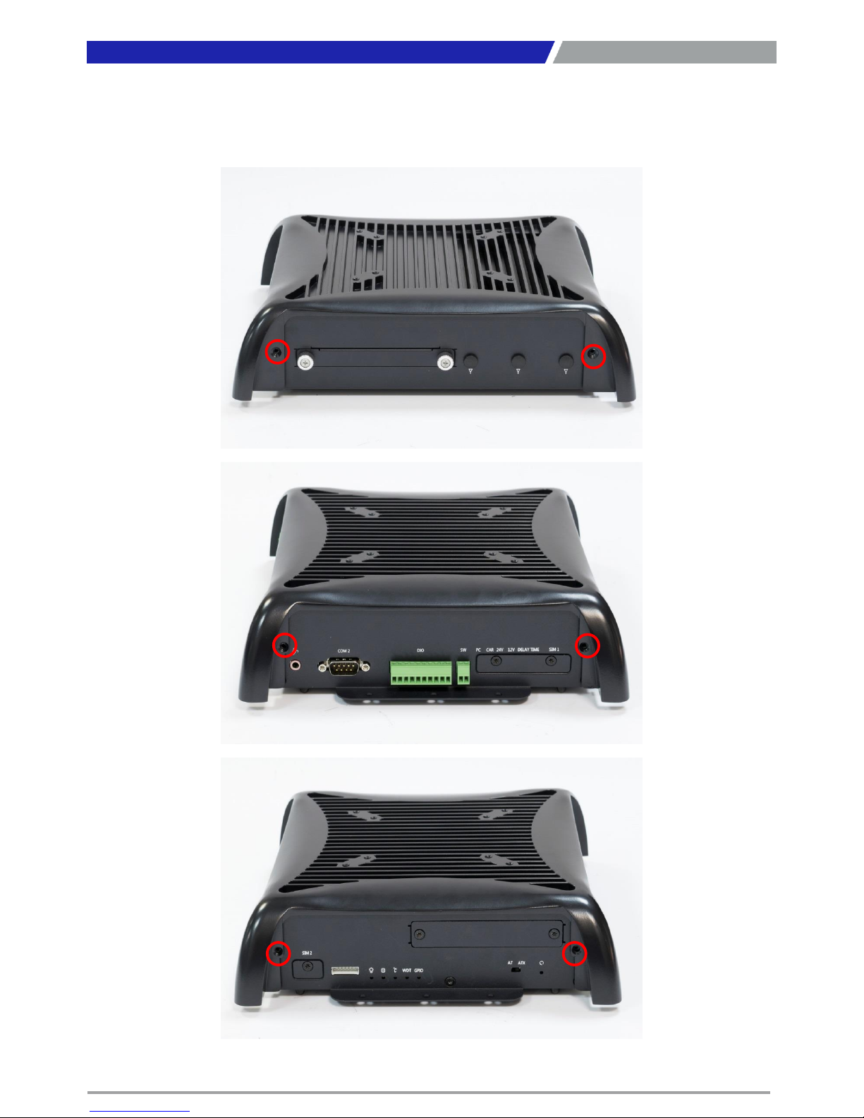
4.11 Screw location for PC311 series top cover
1. Screw location on the top cover of PC311 series is different from PC300. Highlighted as
below.
46
Chapter 3: System Setup
Page 47

Chapter 4
BIOS Setup
Page 48
PC300 / PC311E(P) l User’s Manual
48
4.1 BIOS Introduction
The system BIOS software is stored on EEPROM. The BIOS provides an interface to modify the
configuration. When the battery is removed, all the parameters will be reset.
BIOS Setup
Power on the embedded system and by pressing <Del> or <F2> immediately allows you to enter the
setup screens. If the message disappears before you respond and you still wish to enter the Setup,
restart the system by turning it OFF and ON or pressing the RESET button.
You may also restart the system by simultaneously pressing <Ctrl>, <Alt>, and <Delete> keys.
Main Setup
The main menu lists the setup functions you can make changes to. You can use the arrow keys ( ↑↓ )
to select the item. The on-line description of the highlighted setup function is displayed at the
bottom of the screen.
General Help <F1>
The BIOS setup program provides a General Help screen. You can call up this screen from any menu
by simply pressing <F1>. The Help screen lists the appropriate keys to use and the possible selections
for the highlighted item. Press <Esc> to exit the Help screen.
Chapter 4: BIOS Setup
Control Keys
<←> <→>
Select Screen
<↑> <↓>
Select Item
<Enter>
Select
<Page Up/+>
Increases the numeric value or makes changes
<Page Down/
->
Decreases the numeric value or makes changes
<F1>
General Help
<F2>
Previous Value
<F3>
Load Optimized Defaults
<F4>
Save Configuration and Exit
<Tab>
Select Setup Fields
<Esc>
Exit BIOS Setup
Page 49
PC300 / PC311E(P) l User’s Manual
49
4.2 Main Setup
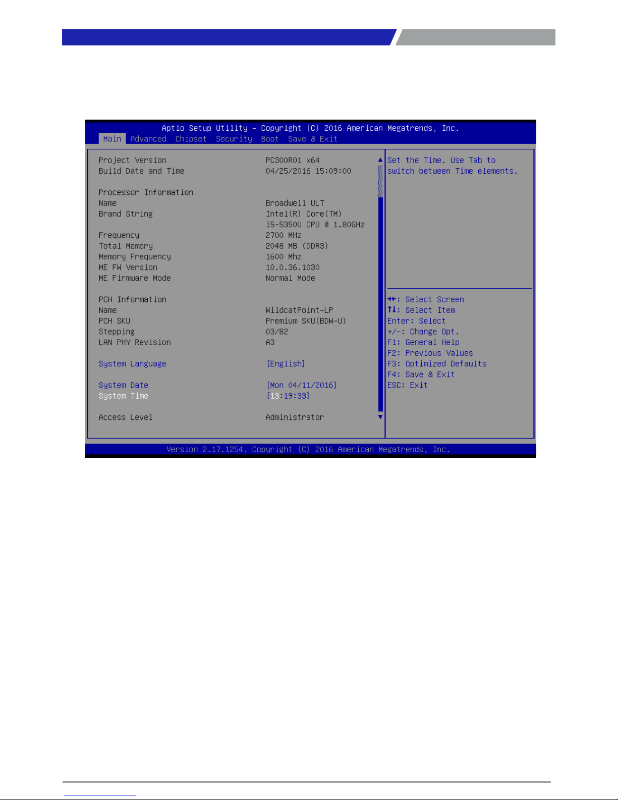
Press <Del> to enter BIOS CMOS Setup Utility, the Main Menu (as shown below) will appears on the
screen. Use arrow keys to move among the items and press <Enter> to accept or enter a sub-menu.
4.2.1 System Language
Set the system language. Please use <Tab> to switch between language elements.
4.2.1 System Date
Set the system date. Please use <Tab> to switch between data elements.
4.2.2 System Time
Set the system time. Please use <Tab> to switch between time elements.
Chapter 4: BIOS Setup
Page 50
PC300 / PC311E(P) l User’s Manual
50
50
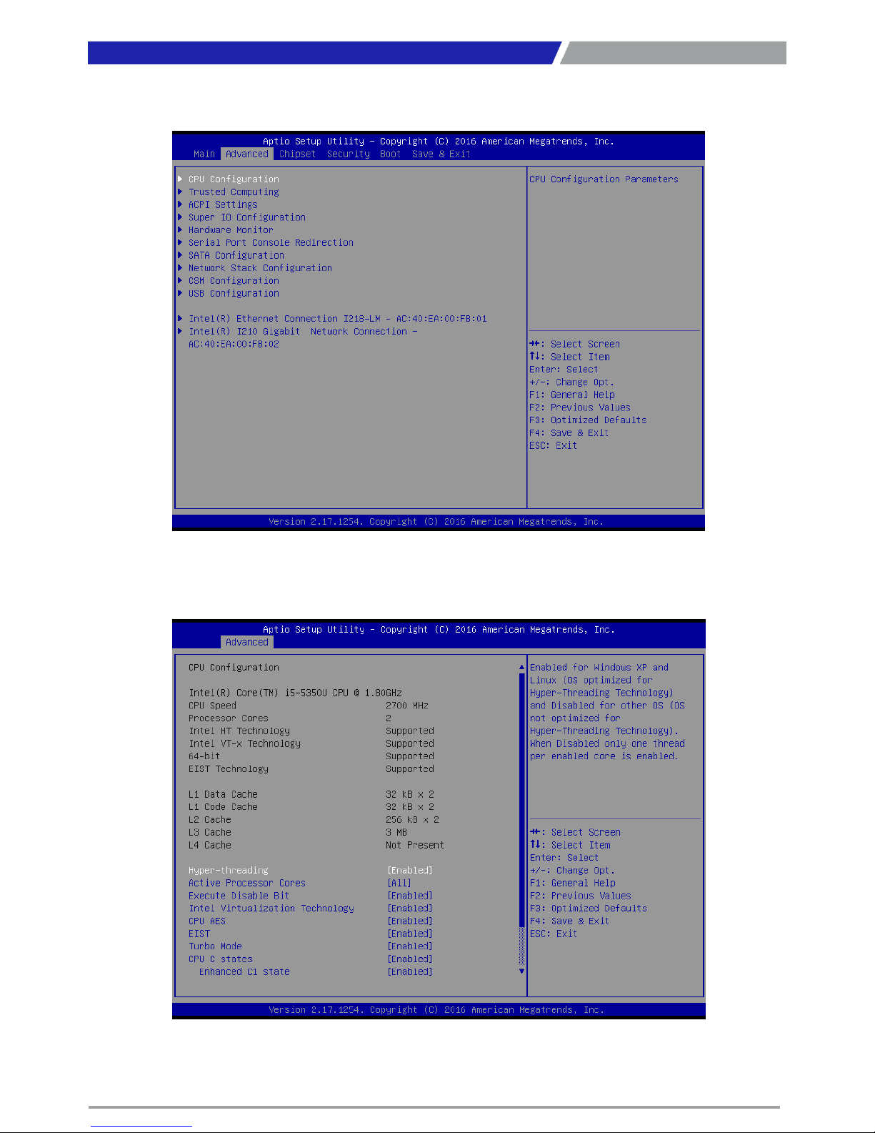
4.3 Advanced Setup
4.3.1 CPU Configuration
Chapter 4: BIOS Setup
Page 51
PC300 / PC311E(P) l User’s Manual
51
51
Chapter 4: BIOS Setup
■ Hyper Threading Technology
This item allows you to enable or disable Intel Hyper Threading technology.
■ Active Processor Cores
This setting specifies the number of active processor cores.
■ Execute Disable Bit
This item allows you to enable or disable the No-Execution page protection technology.
■ Intel Virtualization Technology
This item allows you to enable or disable intel’s virtualization technology.
■ CPU AES
This item allows you to enable or disable CPU Advanced Encryption Standard (AES) instructions.
■ EIST
This item allows you to enable or disable Enhanced Intel SpeedStep Technology (EIST).
■ Turbo Mode
This item allows you to enable or disable Turbo Mode.
■ CPU C States
This item allows you to enable or disable CPU C states.
■ Enhanced C1 State
This item allows you to enable or disable Enhanced C1 state.
■ CPU C3 Report
This item allows you to enable or disable CPU C3 report to OS.
■ CPU C6 Report
This item allows you to enable or disable CPU C6 report to OS.
■ C6 Latency
Configure Short/Long latency for C6.
■ CPU C7 Report
Enable or disable CPU C7 report to OS.
4.3.2 Trusted Computing (Option)
■ Security Device Support
This item allows you to enable or disable BIOS support for security device.
Page 52
PC300 / PC311E(P) l User’s Manual
52
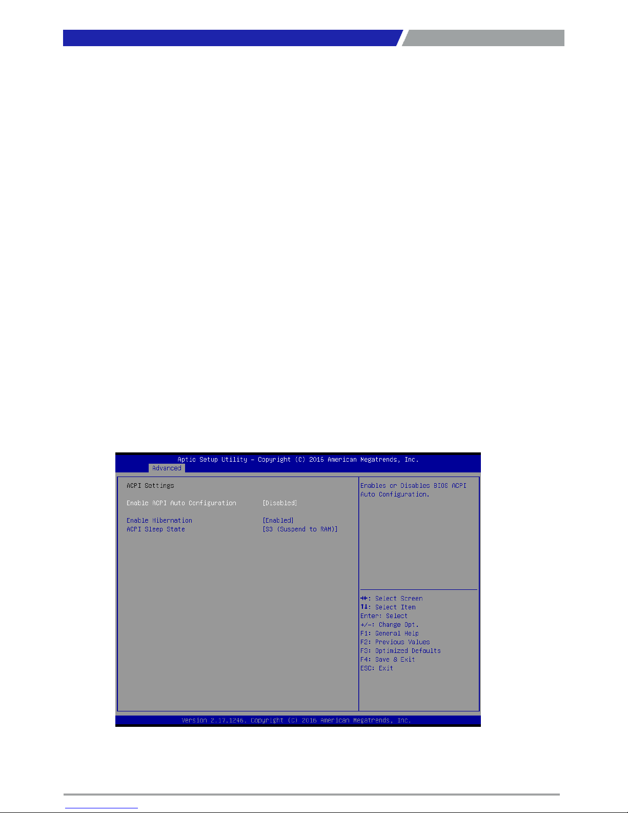
4.3.3 ACPI Settings
Enable or disable ACPI Auto Configuration.
Chapter 4: BIOS Setup
■ Enable ACPI Auto Configuration
This item allows you to enable or disable BIOS ACPI Auto Configuration.
■ Enable Hibernation
This item allows you to enable or disable system ability to hibernate.
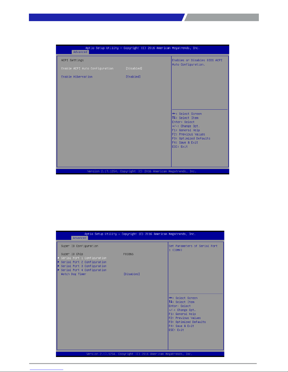
4.3.4 Super IO Configuration
You can use this screen to select options for the Super IO Configuration, and change the value of the
selected option.
Page 53
PC300 / PC311E(P) l User’s Manual
53
53
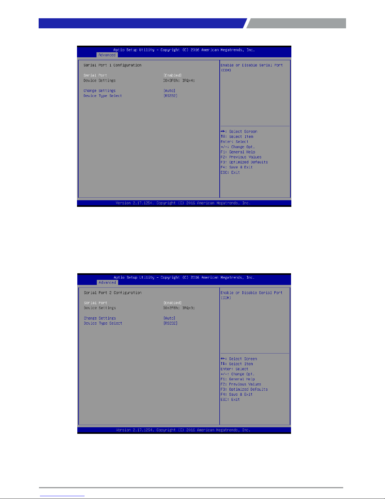
■ Serial Port 1 Configuration
Serial Port
This item will allow you to enable or disable serial port.
Change Settings
This setting is used to change the address & IRQ settings of the specified serial port.
Device Type Select
Change the Serial interface. Select <RS232>, <RS422> or <RS485> interface.
Chapter 4: BIOS Setup
■ Serial Port 2 Configuration
Serial Port
This item will allow you to enable or disable serial port.
Change Settings
This setting is used to change the address & IRQ settings of the specified serial port.
Device Type Select
Change the Serial interface. Select <RS232>, <RS422> or <RS485> interface.
Page 54
PC300 / PC311E(P) l User’s Manual
54
54
Chapter 4: BIOS Setup
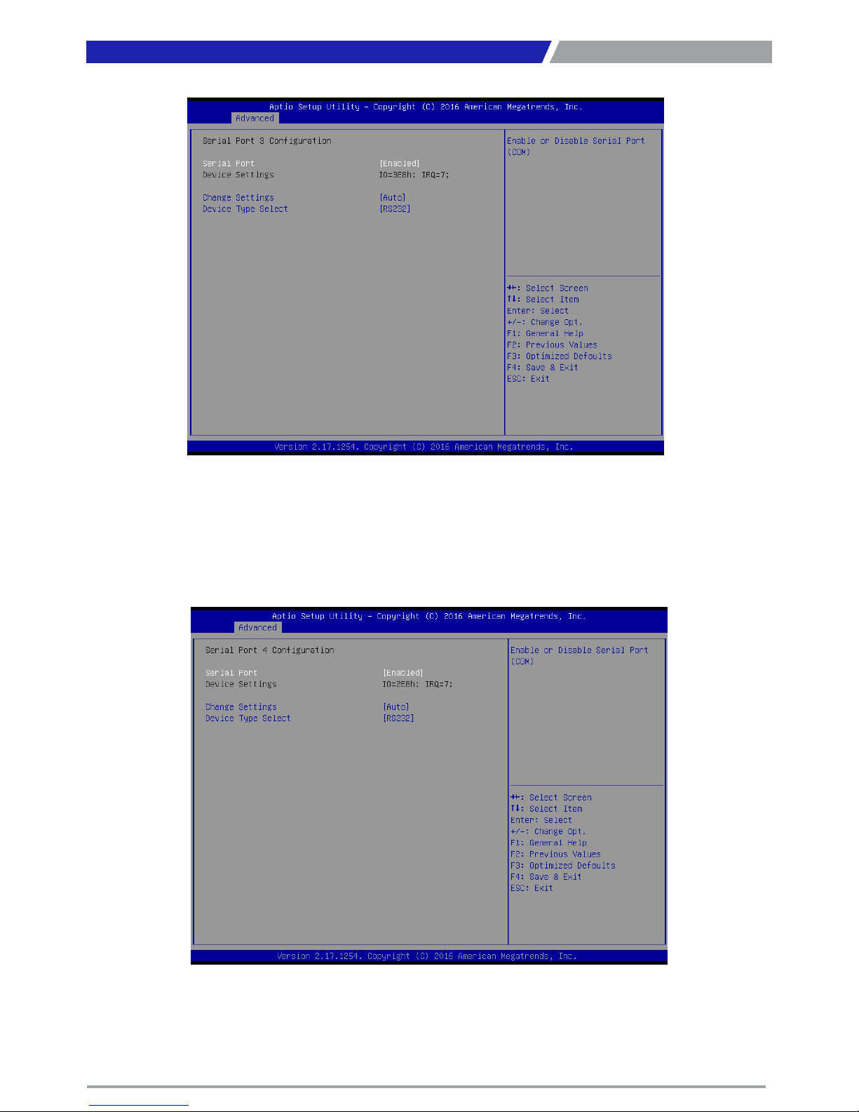
■ Serial Port 3 Configuration
Serial Port
This item will allow you to enable or disable serial port.
Change Settings
This setting is used to change the address & IRQ settings of the specified serial port.
Device Type Select
Change the Serial interface. Select <RS232>, <RS422> or <RS485> interface.
■ Serial Port 4 Configuration
Serial Port
This item will allow you to enable or disable serial port.
Change Settings
This setting is used to change the address & IRQ settings of the specified serial port.
Device Type Select
Change the Serial interface. Select <RS232>, <RS422> or <RS485> interface.
Page 55
PC300 / PC311E(P) l User’s Manual
55
55
■ Watch Dog Timer
You can setup the system watch-dog timer, a hardware timer that generates a reset
when the software that it monitors does not respond as expected each time the watch
dog polls it.
Watch Dog Timer Count Mode
Change the Watch dog mode. Select <Sec> or <Min> mode.
Watch Dog Timer Time Out Value
User can set a value in the range of 0 to 255.
Chapter 4: BIOS Setup
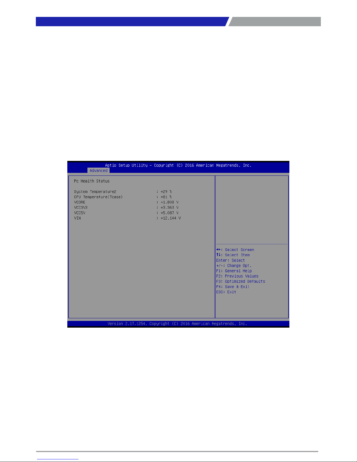
4.3.5 Hardware Monitor
These items display the current status of all monitored hardware devices/ components such as voltages
and temperatures.
Page 56
PC300 / PC311E(P) l User’s Manual
56
56
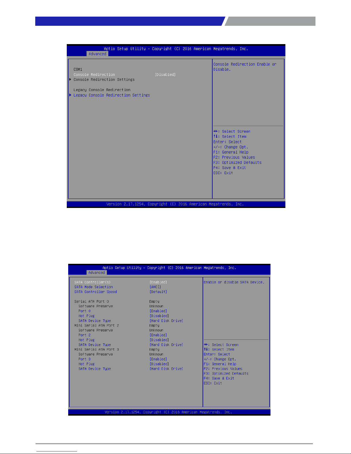
4.3.6 Serial Port Console Redirection
Console Redirection
This item allows you to enable or disable console redirection.
Legacy Console Redirection Settings
Select a COM port to display redirection of legacy OS and legacy OPROM messages.
Chapter 4: BIOS Setup
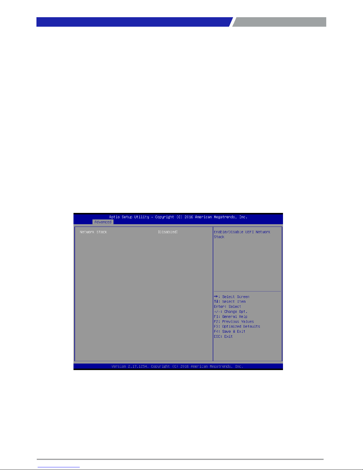
4.3.7 SATA Configuration
Page 57
PC300 / PC311E(P) l User’s Manual
57
Chapter 4: BIOS Setup
■ SATA Controller(s)
This item allows you to enable or disable SATA Controller.
■ SATA Mode Selection
This item allows you to select AHCI or RAID Mode.
■ SATA Controller Speed
The item is for you to set the maximum speed the SATA controller can support.
Change the SATA Speed. Select <Default>, <Gen1>, <Gen2> or <Gen3> speed.
■ Serial ATA Port 0 / 2 / 3
Port 0 / 2 / 3
This item allows you to enable or disable Serial ATA Port 0 / 2 / 3.
Hot Plug
This item allows you to enable or disable hot plug function.
SATA Device Type
Identify if the relevant SATA port is connected to hard disk drive or solid state
drive.
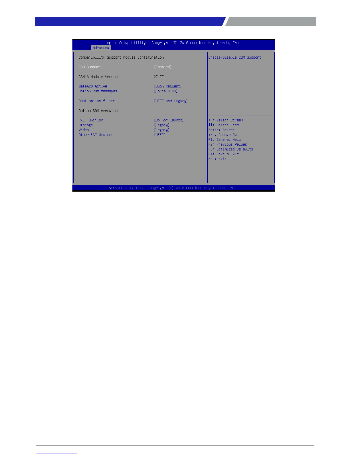
4.3.8 Network Stack Configuration
■ Network Stack
Use this item to enable or disable UEFI Network Stack.
Page 58
PC300 / PC311E(P) l User’s Manual
58
4.3.9 CSM Configuration
■ CSM Support
This item allows you to enable or disable CSM support.
■ GateA20 Active
This item allows you to select <Upon Request> or <Always>.
Upon Request: GA20 can be disabled using BIOS services.
Always: Do not allow GA20 disabling. This option is useful when any RT code is
executed above 1MB.
■ Option ROM Messages
This item allows you to select <Force BIOS> or <Keep Current>.
Force BIOS : The third-party ROM messages will be forced to display during the boot
sequence.
Keep Current : The third-party ROM messages will be displayed only if the third-party
manufactured had set the add-on device to do so.
■ Boot option filter
This item allows you to select which type of operating system to boot.
UEFI and Legacy: Allows booting from operating systems that support legacy option
ROM or UEFI option ROM.
Legacy only: Allows booting from operating systems that only support legacy option
ROM.
UEFI only: Allows booting from operating systems that only support UEFI option ROM.
■ PXE Function
This item controls the execution of UEFI and PXE option ROM. Select <Do not launch>,
<UEFI> or <Legacy>.
■ Storage
This setting allows you to select whether to enable the UEFI or legacy option ROM
for the storage device controller. Select <Do not launch>, <UEFI> or <Legacy>.
■ Video
This setting allows you to select whether to enable the UEFI or legacy video option
ROM for the video device controller. Select <Do not launch>, <UEFI> or <Legacy>.
■ Other PCI devices
This item determines option ROM execution policy for devices other than Network,
storage or video. Select <Do not launch>, <UEFI> or <Legacy>.
Chapter 4: BIOS Setup
Page 59
PC300 / PC311E(P) l User’s Manual
59
Chapter 4: BIOS Setup
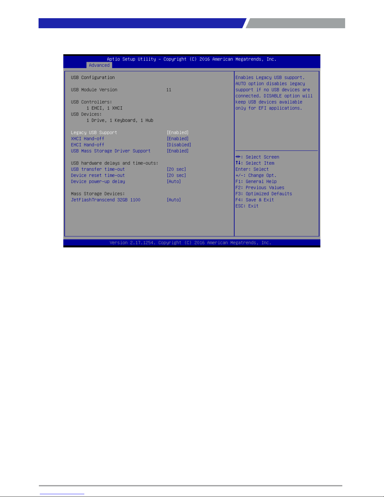
4.3.10 USB Configuration
■ Legacy USB Support
Allows USB keyboard/ mouse to be used in MS-DOS.
■ XHCI Hand-off
Determines whether to enable XHCI (USB3.0) Hand-off feature for an operating system without
XHCI (USB3.0) Hand-off support.
■ EHCI Hand-off
Determines whether to enable EHCI Hand-off feature for an operating system without EHCI Handoff support.
■ USB Mass Storage Driver Support
Enables or disables support for USB storage devices.
■ USB transfer time-out
Set the time-out value for Control, Bulk, and Interrupt transfers.
■ Device reset time-out
Set USB mass storage device Start Unit command time-out value.
■ Device power-up delay
Set the maximum time of the device will take before it properly reports itself to the Host Controller.
'Auto' uses default value: for a Root port it is 100 ms, for a Hub port the delay is taken from Hub
descriptor.
Page 60
PC300 / PC311E(P) l User’s Manual
60
Chapter 4: BIOS Setup
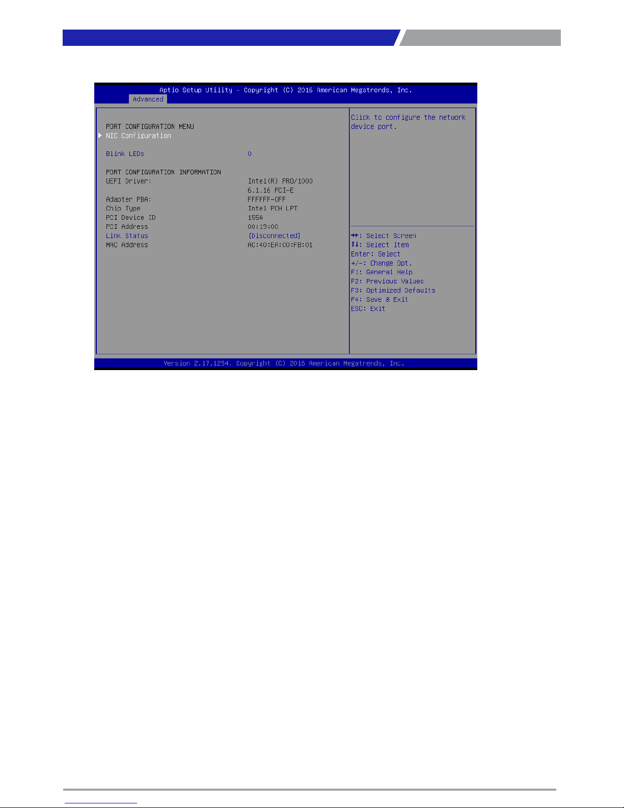
4.3.11 Intel(R) Ethernet Connection I218-LM-XX:XX:XX:XX:XX:XX
■ NIC Configuration
Press enter to configure the network device port.
■ Blink LEDs
Use this item to identify the physical network port by blinking the associated LED.
■ Link Status
Use this item to specify the port speed used for the selected boot protocol. Select <Auto
Negotiated>, <10 Mbps Half>, <10 Mbps Full>, <100 Mbps Half> or <100 Mbps Full>.
Link Speed
Use this item to specify the port speed used for the selected boot protocol. Select <Auto
Negotiate>, <10 Mbps Half>, <10 Mbps Full>, <100Mbps Half> or <100 Mbps Full>.
Wake On LAN
Enables the server to be powered on using an in-band magic packet.
Page 61
PC300 / PC311E(P) l User’s Manual
6161
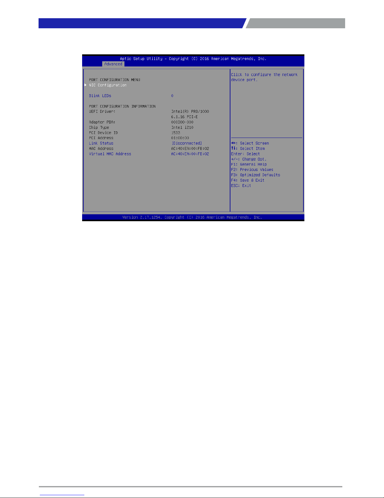
4.3.12 Intel(R) I210 Gigabit Network Connection- XX:XX:XX:XX:XX:XX
Chapter 4: BIOS Setup
■ NIC Configuration
Press enter to configure the network device port.
■ Blink LEDs
Use this item to identify the physical network port by blinking the associated LED.
■ Link Status
Use this item to specify the port speed used for the selected boot protocol. Select <Auto
Negotiated>, <10 Mbps Half>, <10 Mbps Full>, <100 Mbps Half> or <100 Mbps Full>.
■ Virtual MAC Address
Displays the programmatically assignable MAC Address.
Link Speed
Use this item to specify the port speed used for the selected boot protocol. Select <Auto
Negotiated>, <10 Mbps Half>, <10 Mbps Full>, <100Mbps Half> or <100 Mbps Full>.
Wake On LAN
Enables the server to be powered on using an in-band magic packet.
Page 62
PC300 / PC311E(P) l User’s Manual
62
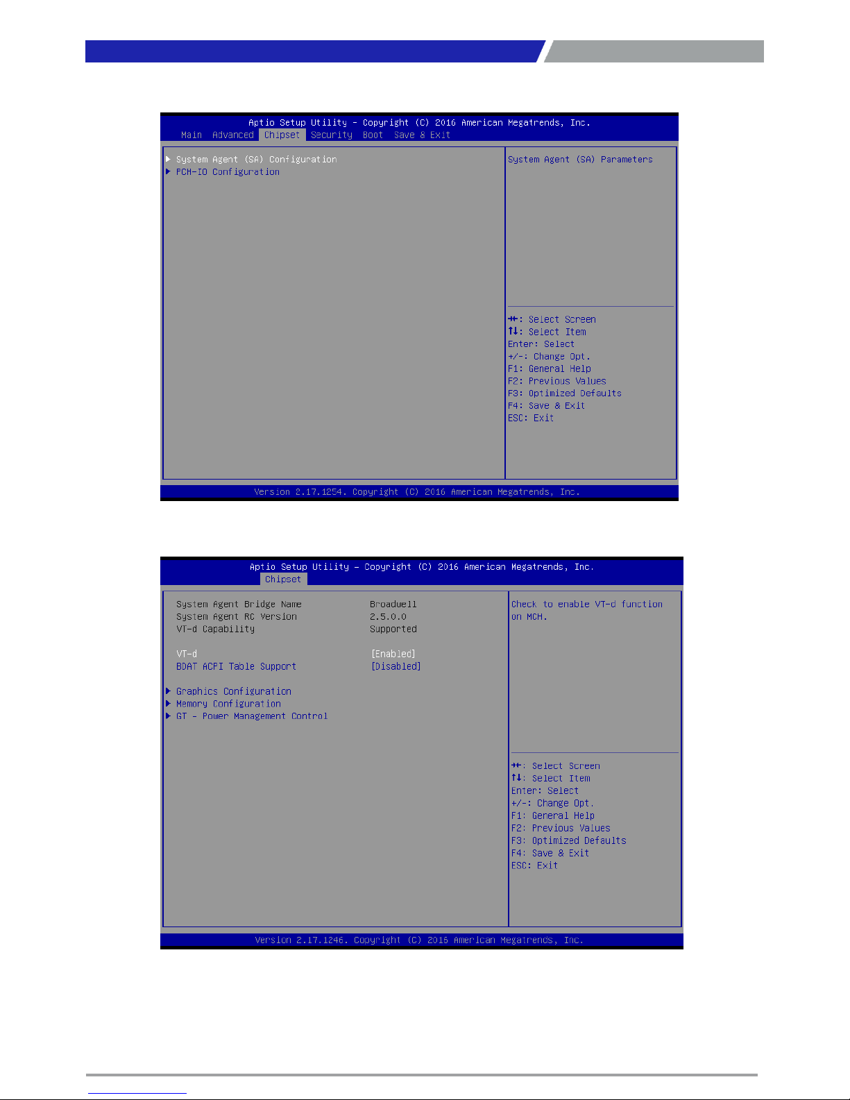
4.4 Chipset
Chapter 4: BIOS Setup
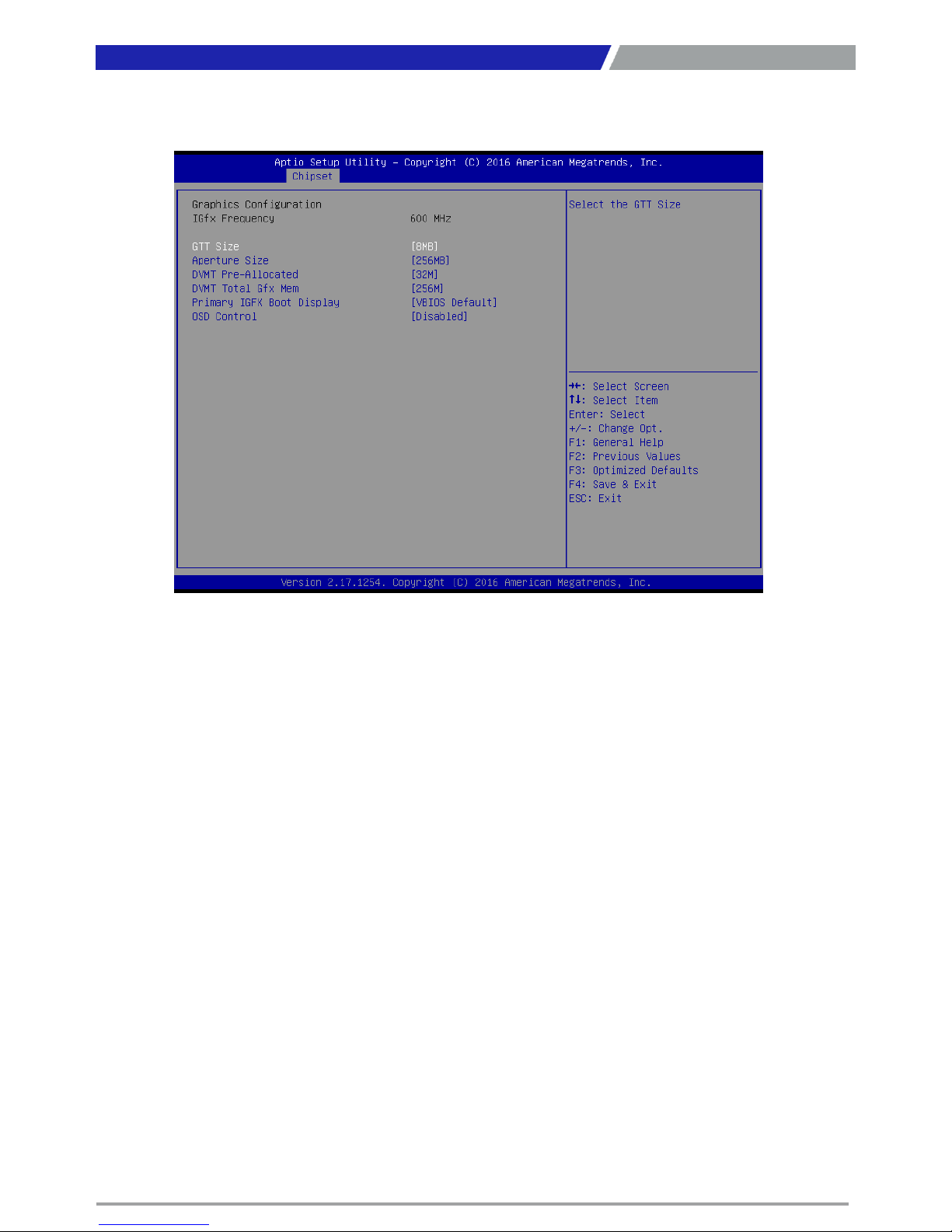
4.4.1 System Agent (SA) Configuration
Page 63
PC300 / PC311E(P) l User’s Manual
63
Chapter 4: BIOS Setup
GTT Size
This item allows you to change the GTT size.
Aperture Size
This item allows you to change the Aperture size.
DVMT Pre-Allocated
Used the DVMT Pre-Allocated option to specify the amount of system memory that can be used
by the internal graphics device.
DVMT Total Gfx Mem
This setting specifies the memory size for DVMT.
Primary IGFX Boot Display
Use the field to select the type of device you want to use as the display(s) of the system.
OSD Control
This item allows you to enable or disable OSD Control.
▶ Graphics Configuration
Use this item to configure internal graphics controller.
Page 64
PC300 / PC311E(P) l User’s Manual
64
Chapter 4: BIOS Setup
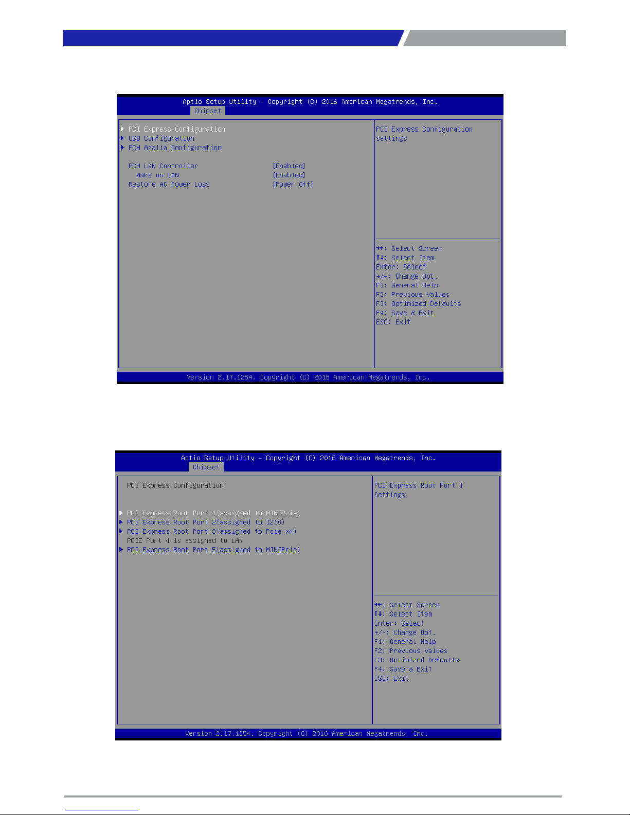
4.4.2 PCH-IO Configuration
▶ PCI Express Configuration
Page 65
PC300 / PC311E(P) l User’s Manual
65
Chapter 4: BIOS Setup
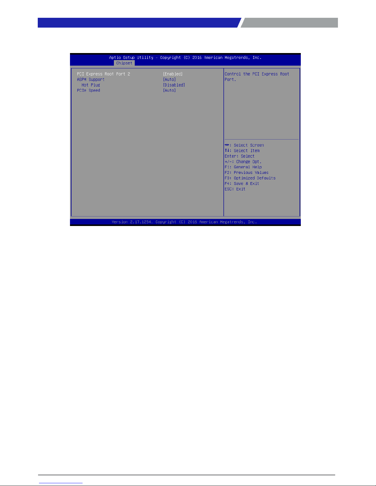
PCI Express Root Port 1 / 2 / 3 / 5
PCI Express Port 1 / 2 / 3 / 5
This item allows you to enable or disable PCI Express Port 2 / 4 / 5 / 6 in the chipset.
ASPM
This item allows you to select the ASPM state for energy-saving. Select <Disabled> ,<L0s>, <L1>,
<L0sL1> or <Auto>
Hot Plug
This item allows you to enable or disable hot plug function.
PCIe Speed
Change the PCIe Port Speed. Select <AUTO> ,<Gen 1> or <Gen 2>
Page 66
PC300 / PC311E(P) l User’s Manual
66
Chapter 4: BIOS Setup
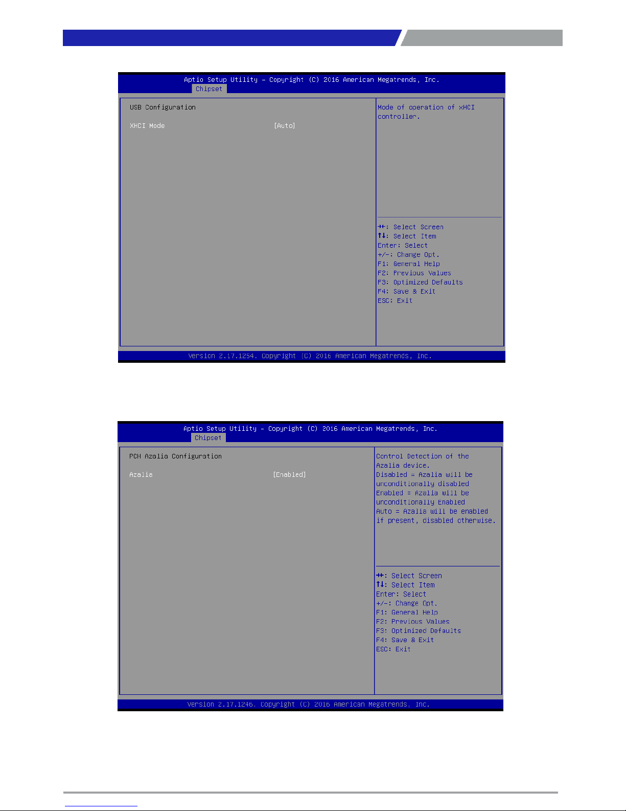
▶ USB Configuration
XHCI Mode
Mode of operation of XHCI controller.
Azalia
Control Detection of the Azalia device. This item allows you to select <Enabled>, <Disabled> or <Auto>.
Disabled: Azalia will be unconditionally be disabled.
Enabled: Azalia will be unconditionally be enabled.
Auto: Azalia will be enabled if present, disabled otherwise.
▶ PCH Azalia Configuration
Page 67
PC300 / PC311E(P) l User’s Manual
67
■ PCH LAN Controller
This item allows you to enable or disable the onboard PCH integrated ethernet controller.
■ Wake on LAN
This item allows you to enable or disable wake on LAN function.
■ Restore AC Power Loss
This item specifies whether your system will reboot after a power failure or interrupt occurs.
Available settings are:
Power Off: Leave the computer in the power off state.
Power On: Leave the computer in the power on state.
Last State: Restore the system to the previous status before power failure or interrupt occurred.
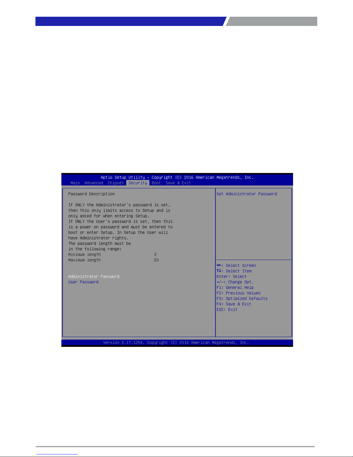
4.5 Security
This section allows you to configure and improve your system and allows you to set up some system
features according to your preference.
4.5.1 Administrator Password
Administrator Password controls access to the BIOS Setup utility.
4.5.2 User Password
User Password controls access to the system at boot and to the BIOS Setup utility.
Page 68
PC300 / PC311E(P) l User’s Manual
68
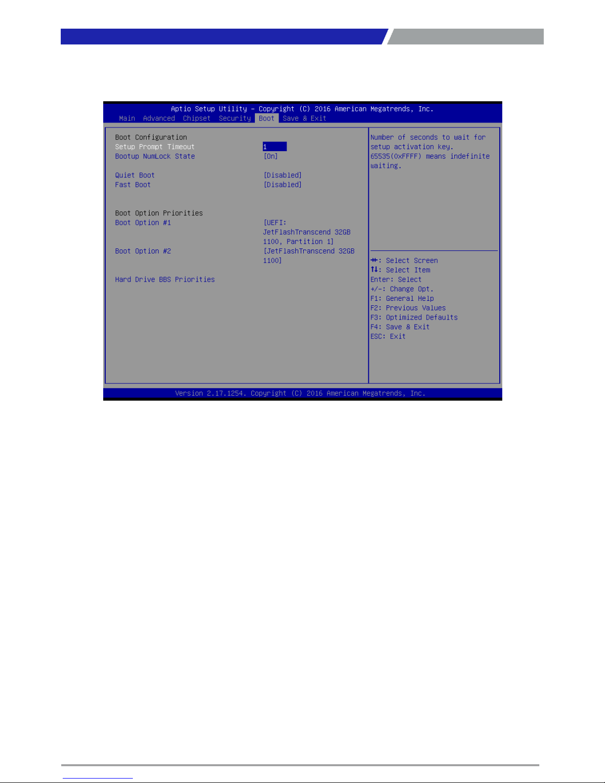
4.6 Boot
This section allows you to configure the boot settings.
4.6.1 Setup Prompt Timeout
User Password controls access to the system at boot and to the BIOS Setup utility.
4.6.2 Bootup NumLock State
Select the Power-on state for Numlock.
4.6.3 Quiet Boot
This item allows you to enable or disable Quiet Boot option.
4.6.4 Fast Boot
This item allows you to enable or disable Fast Boot option.
4.6.5 Hard Driver BBS Priorities
The items specify the boot device priority sequence from the available devices. The number of device
items that appears on the screen depends on the number of devices installed in the system.
Chapter 4: BIOS Setup
Page 69
PC300 / PC311E(P) l User’s Manual
69
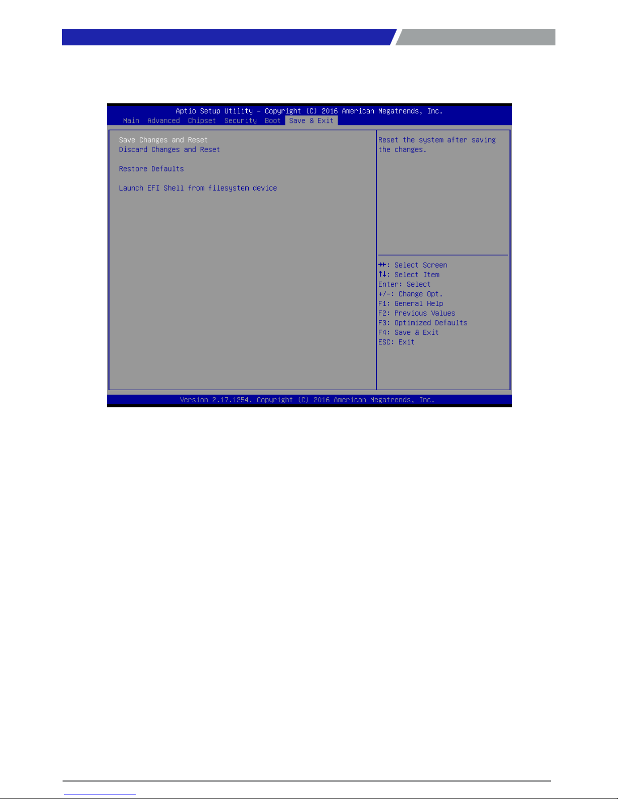
4.7 Save & Exit
This section allows you to configure the boot settings.
4.7.1 Save Changes and Reset
This item allows you to reset system setup after saving changes.
4.7.2 Discard Changes and Reset
This item allows you to reset system setup without saving any changes.
4.7.3 Restore Defaults
This item allows you to restore/ load default values for all the options.
4.7.4 Lauch EFI Shell from filesystem device
Use this item to launch EFI shell application (shell.efi) from one of the available filesystem device.
Chapter 4: BIOS Setup
Page 70

Appendix
WDT & GPIO
This appendix provides the sample codes of WDT (Watch
Dog Timer) and GPIO (General Purpose Input/ Output).
Page 71

PC300 / PC311E(P) l User’s Manual
71
WDT Sample Code
SIO_INDEX_Port equ 02Eh
SIO_DATA_Port equ 02Fh
SIO_UnLock_Value equ 087h
SIO_Lock_Value equ 0AAh
WatchDog_LDN equ 007h
WDT_UNIT equ 60h ;60h=second, 68h=minute, 40h=Disabled Watchdog timer
WDT_Timer equ 30 ;ex. 30 seconds
Sample code:
;Enable config mode
mov dx, SIO_INDEX_Port
mov al, SIO_UnLock_Value
out dx, al
jmp short $+2 ;Io_delay
jmp short $+2 ;Io_delay
out dx, al
;Change to WDT
mov dx, SIO_INDEX_Port
mov al, 07h
out dx, al
mov dx, SIO_DATA_Port
mov al, WatchDog_LDN
out dx, al
;Acive WDT
mov dx, SIO_INDEX_Port
mov al, 30h
out dx, al
mov dx, SIO_DATA_Port
in al, dx
or al, 01h
out dx, al
;set timer
mov dx, SIO_INDEX_Port
mov al, 0F6h
out dx, al
mov dx, SIO_DATA_Port
mov al, WDT_Timer
out dx, al
;set UINT
mov dx, SIO_INDEX_Port
mov al, 0F5h
out dx, al
mov dx, SIO_DATA_Port
mov al, WDT_UNIT
out dx, al
;enable reset
mov dx, SIO_INDEX_Port
mov al, 0Fah
out dx, al
mov dx, SIO_DATA_Port
in al, dx
or al, 01h
out dx, al
;close config mode
mov dx, SIO_INDEX_Port
mov al, SIO_Lock_Value
out dx, al
Appendix – WDT & GPIO
Page 72
PC300 / PC311E(P) l User’s Manual
72
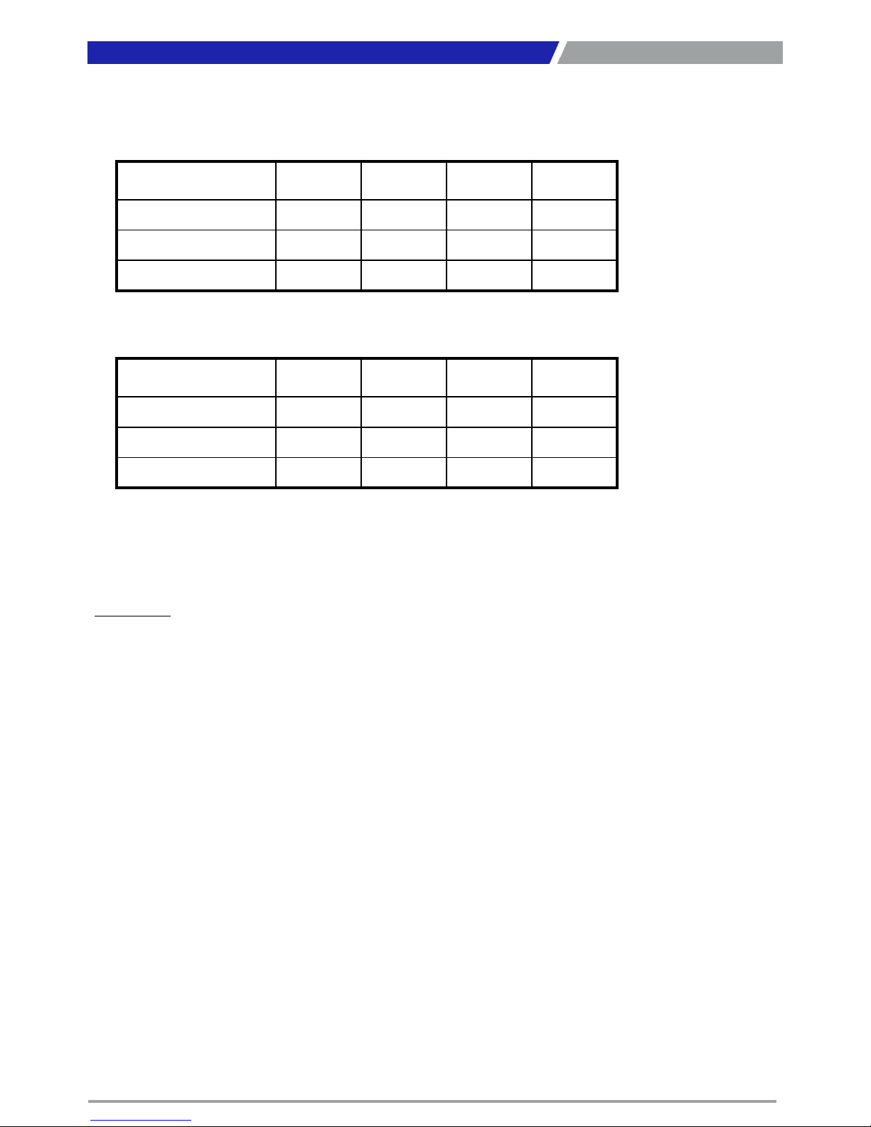
GPIO Sample Code
GPI 0 ~ GPI 3
GPO 0 ~ GPO 3
GPI_REG equ 0A03h
GPO_REG equ 0A02h
GPO_0 equ 00010000b
____________________________________________________________________________________
Sample Code:
#1 : Get GPI 0 status
; Get GPI 0 Pin Status Register
In al, GPI_REG
;al bit4 = GPI 0 status
#2 : Set GPO 0 status to high
; Set GPO 0 Pin to High
mov dx, GPO_REG
in al, dx
or al, GPO_0
out dx, al
;al bit0 = GPO 0 status
Appendix – WDT & GPIO
GPI 0 GPI 1 GPI 2 GPI 3
IO Address 0xA03h 0xA03h 0xA03h 0xA03h
Bit 4 5 6 7
Sample code #1
GPO 0 GPO 1 GPO 2 GPO 3
IO Address 0xA02h 0xA02h 0xA02h 0xA02h
Bit 0 1 2 3
Sample code #2
Page 73

Copyright 2016 C&T Solution Inc. All Rights Reserved
www.candtsolution.com
 Loading...