

Page 1
CS UNITEC
Operating Manual
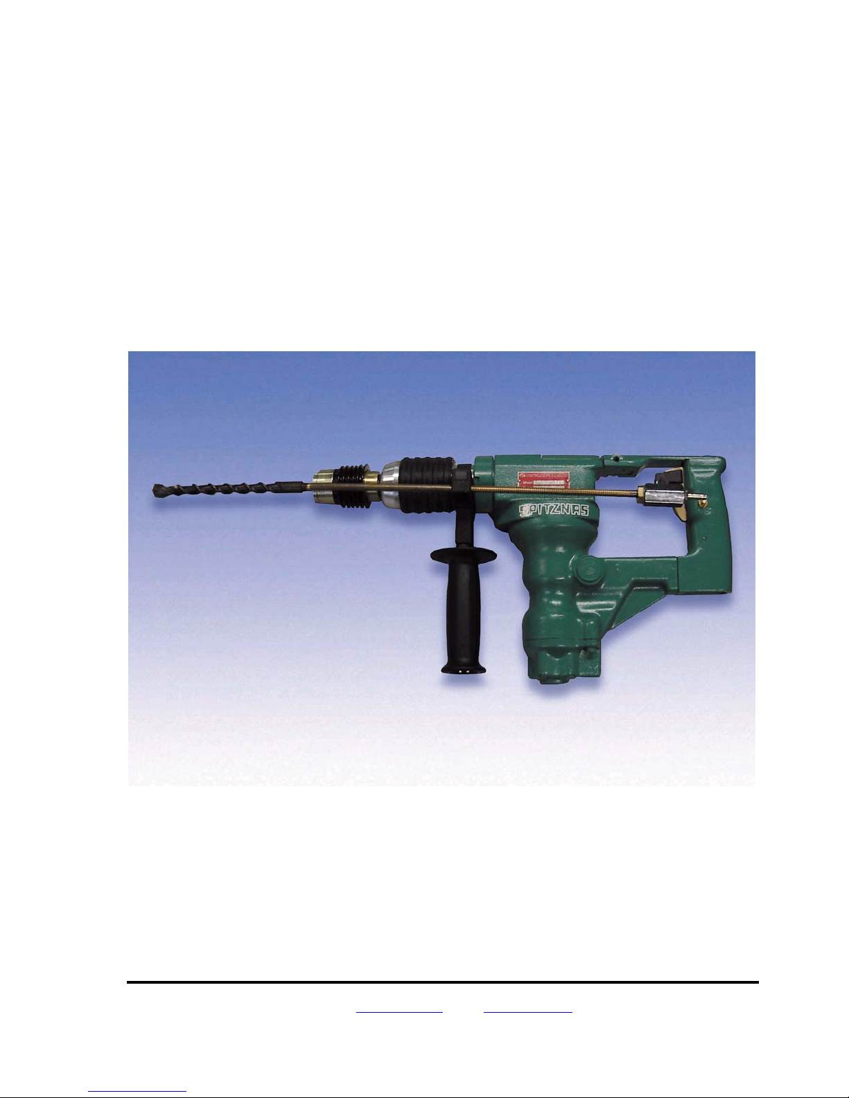
Hydraulic-Rotary Hammer
2 2406 0010
22 Harbor Avenue Norwalk, CT 06850 800 700-5919 203 853-8522 Fax 203 853-9921
Abweichung der Darstellung mögli ch
Website: www.csunitec.com E-mail: [email protected]
Page 1 of 6
Page 2

Hydraulic Rotary Hammer 2 2406 0010 CS UNITEC
SAFETY INSTRUCTIONS
Any power tool can be dangerous. Please follow these simple safety
procedures – they are for your protection.
• Do not use this product in anyway other than as directed by these operating instructions.
• When working with the machine, it must be held with two hands. Always make sure that you
have a safe stance / foothold.
• Regular maintenance is essential – check screws, fittings etc. for tightness
Check hydraulic line for damage
•
• Never use blunt drills
• Wear goggles, gloves and ear protection
• Always disconnect oil when changing drills or working on the machine
• Remove rings, watches, ties etc. that could tangle in the moving parts
WARNING! Never use the flexible hose as a lifting handle!
Your safety is in your hands! Keep these instructions!
Noise and vibration levels
Typically the A-weighted noise levels of the tool are:
• Sound pressure level: 92 dB(A)
Wear ear protection.
The typical weighted acceleration is 14.8 ft./s
2
.
22 Harbor Avenue Norwalk, CT 06850 800 700-5919 203 853-8522 Fax 203 853-9921
Website: www.csunitec.com E-mail: [email protected]
Page 2 / 6
Page 3

Hydraulic Rotary Hammer 2 2406 0010 CS UNITEC
SPECIFICATIONS
Oil connector: SAE PORT No.8
Operating pressure: max. 1450 PSI (100 bar)
consumption: 5.8-13.2 gallons/min.
Power .8 HP
Water connection ball cock: R1/4"
Free speed: 0-625 RPM
Load speed: 0-500 RPM
Hammering under load: 0-3400 blows/min
Drilling performance in medium-hard concrete: 1/2” dia = 13.4” 3/min. = 12” /min
Drill bits for concrete: 3/16”-1-1/16” dia.
Performance optimum in concrete: 1/2”-3/4” dia.
Percussion core bits for concrete: 2-1/2”-3-1/2” dia.
Twist drills for steel: 3/16”-1/2” dia.
Drill bits for wood: 3/16”-1-3/16” dia.
Weight: 18 lbs. (w/o Hoses)
Safety clutch for protection against overloading and accidents
Gears sealed dust tight with central and permanent lubrication (maintenance free)
Adjustable side handle with depth gauge and water flushing.
Supplied kit: 1 case, 1 dust guard,
22 Harbor Avenue Norwalk, CT 06850 800 700-5919 203 853-8522 Fax 203 853-9921
Website: www.csunitec.com E-mail: [email protected]
Page 3 / 6
Page 4

Hydraulic Rotary Hammer 2 2406 0010 CS UNITEC
START-UP AND OPERATION
Do not exert undue pressure on the rotary hammer. This will not increase its performance. Just
position the bit and guide it into the hole.
Placing the tool into case: Make sure the adjusting sleeve is locked at the setting "Rotary
hammer drilling"
Side handle: This can be turned through 360° and clamped in any desired position.
Depth gauge:
Lubrication of chuck: Occasionally lubricate drill bit connection ends and spray sparingly with
lubricant sprayer. Do not spray into the chuck.
Fig. 1 Fig. 2 Fig. 3 Fig. 4 Fig. 5
Press unlock button, adjust the depth gauge and release button.
Í
DRILLING IN EXPLOSIVE SURROUNDINGS
: The drill bit must be water cooled to avoid sparks. Water connection on ball cock.
Fig.1
DRILLING IN EXPLOSIVE SURROUNDINGS
Fig.1: The drill bit must be water cooled to avoid sparks. Water connection on ball cock.
ROTARY HAMMER DRILLING
Fig.2: Pull back the adjusting sleeve and turn it clockwise to lock. Do not use the quick-release
chuck at this setting because drill bits will be damaged.
Fig.3: Pull back the locking sleeve and insert the drill bit. Turn the locking sleeve until it snaps back
into the outset position. Press the drill bit against the work surface before switching on otherwise
the tool will not hammer. If the drill bit sticks in the hole, withdraw and reinsert it several times
when drilling.
Fig.4: When starting to drill into brittle materials (tiles etc), unlock the adjust ing sleeve to "Rotary
drilling only", hold the tool by the adjusting sleeve and press it slowly against the work surface until
it hammers weakly. Hold and continue to drill the hole. Switch off the tool briefly and relock the
adjusting sleeve.
ROTARY DRILLING ONLY
Fig. 5: Unlock the adjusting sleeve. The quick-release chuck is used at this setting. Commercially
available HS twist drills can be used in the quick-release chuck.
22 Harbor Avenue Norwalk, CT 06850 800 700-5919 203 853-8522 Fax 203 853-9921
Website: www.csunitec.com E-mail: [email protected]
Page 4 / 6
Page 5

Hydraulic Rotary Hammer 2 2406 0010 CS UNITEC
HYDRAULIC SYSTEM REQUIREMENTS
The hydraulic system should provide a flow of 5.8-13.2 gpm / 22-50 lpm at an operating pressure
of 950-1450 / 66-100 bar.
WARNING!
Never use your hydraulic tool without a pressure relief valve in line!
The system should not have more than 250 psi / 17 bar back pressure measured at the tool end of
the operating hoses. The system conditions for measurement are at maximum fluid viscosity or
400 ssu / 82 centistokes (minimum operating temperatures).
The hydraulic system should have sufficient heat rejection capacity to limit the maximum oil
temperature to 140° F / 60° C at the maximum expected ambient temperature. The recommended
minimum cooling capacity is 5 hp / 3.73 kW at a 40° F / 4° C difference between ambient
temperature and oil temperature.
The hydraulic system should have a minimum of 25 micron full-flow filtration. It is recommended
that filter elements be sized for a flow of at least 30 gpm / 114 lpm for cold temperature startup and
maximum dirt holding capacity.
The hydraulic fluid used should have a viscosity between 100 and 400 ssu / 20 and 82 centistokes
at the maximum and minimum expected operating temperatures. Petroleum base hydraulic fluids
with anti-wear and non-conductive properties and a viscosity index over 140 meet the
recommended requirements over a wide range of operating temperatures.
The recommended hose size is .500 inch / 12 mm I.D. to 50 ft / 15 m long and .625 inch / 16 mm
I.D. minimum up to 100 ft / 30 m long.
The drill return hose must connect directly to the circuit return line and go straight through the oil
filter, thermal valve, and oil cooler to the reservoir. To prevent trapped or reversed pressure, fluid
should not be returned through a blocking or reversing valve.
Do not use emulsifying hydraulic fluids. Keep the recommended fluids drained of settled moisture.
Water in the fluid can cause pump cavitation.
The Core Drill cannot be operated with the hydraulic flow reversed. Supply (IN) and return (OUT)
hoses must be connected as marked on the sides of the tool ports.
IMPORTANT!
Do not run the tool return hose through stack or directional valves. If the circuit is operated
from a stack valve, tap only the pressure port to the valve. Connect the tool return directly
to the return fluid line
Your Hydraulic Core Drill is an open-center tool. Operate open-center tools from open-center
hydraulic circuits only. Operate closed-center tools from closed-center hydraulic circuits only.
IDENTIFYING CIRCUIT TYPE
(OC OR CC)
Your circuit type can be determined by the pump and valves in the hydraulic circuit. If the tool
pressure supply is from an accumulator, the circuit is closed-center (CC). If pressurized fluid is
22 Harbor Avenue Norwalk, CT 06850 800 700-5919 203 853-8522 Fax 203 853-9921
Website: www.csunitec.com E-mail: [email protected]
Page 5 / 6
Page 6

Hydraulic Rotary Hammer 2 2406 0010 CS UNITEC
from a pressure-compensated pump or is from the same lines that feed a CC stack valve, the
circuit is CC.
If the pump is variable displacement and pressure compensated, or if the tool pressure supply is
taken from an accumulator charging valve bypass line, open-center (OC) tools can be operated
even though other operations, such as booms, might be powered by CC circuits.
OC circuits are recommended for hand-held tools because fluid temperature and flow can be
controlled over a wide range of tool pressure requirements. In addition, fixed displacement pumps
can be used to warm fluid in cold weather operations, yet keep fluid cool during prolonged
operations.
EQUIPMENT PROTECTION AND CARE
IMPORTANT!
In addition to the Safety Precautions on pages 2 and 3 of this manual,
observe the following for equipment protection and care.
Always store the tool in a clean, dry space, safe from damage or pilferage.
Always keep critical tool markings, such as labels and stickers, legible.
Always replace hoses, couplings and other parts with replacement parts recommended by
SPITZNAS. Supply hoses must have a minimum working pressure rating of 2500 psi / 175 bar.
Always use hoses that have an oil resistant inner surface and an abrasive resistant outer surface.
Whenever near electrical conductors, use clean hose labeled and certified non-conductive hose.
Tool repair should be performed by experienced personnel only.
Make sure all couplers are wiped clean before connection.
The hydraulic power supply valve must be in the "OFF" position when coupling or uncoupling
hydraulic tools. Failure to do so can result in damage to the quick couplers and cause overheating
of the hydraulic system.
Do not exceed 13.2 gpm / 50 lpm flow rate. Rapid failure of the tool's internal seals might result.
Make sure the circuit PRESSURE hose (with male quick disconnect) is connected to the "IN" port
below the right-hand side of the tool. The circuit RETURN hose (with female quick disconnect) is
connected to the "OUT" port below the tool center.
Do not reverse the fluid flow from that marked on the tool ports. Flows, when reversed, will not be
limited by the priority flow control valve
Always use the open-center (OC) tool on open-center circuits.
22 Harbor Avenue Norwalk, CT 06850 800 700-5919 203 853-8522 Fax 203 853-9921
Website: www.csunitec.com E-mail: [email protected]
Page 6 / 6
 Loading...