


INSTRUCTIONMANUAL
VENEXIA 15-18-21-25
MURANO15-18
INGLESE
ENGLISH
You have just purchased a high quality product produced entirely in Italy.
Reading this manual is very important to guarantee correct functioning of the product in regards to
safety and servicing of the machine.
The correct installation and set up of initial parameters is vital and therefore reserved for technicians
that have been authorised by the manufacturer, the same is true for periodic maintenance.
Cleaning is fundamental for safeguarding safety and product operation, it must be carried out
periodically to guarantee long product life and for people and machine safety.
WARNING FOR THE CORRECT DISPOSAL OF PRODUCT WASTE
Waste disposal of electric and electronic appliances (RAEE) as per Legislative Decree 49/2014
implementation of the European Directive 2012/19/EU.
At the end of its working life, the product must not be disposed of with household waste
but be taken to a special differentiated waste collection center or to a dealer providing
this service.
To dispose of the device separately allows to avoid potential negative consequences for
the environment and human health deriving from inappropriate disposal and it promotes
recycling of the materials of which it is composed.
As a reminder of the need to dispose of appliances separately, the product is marked with a crossed
out wheeled bin.
INDEX
1 Safety warnings ................................................................................................................... 2
2 Product description ........................................................................................................... 3
3 Pellet quality ........................................................................................................................ 3
4 Dimensions and hydraulic fittings ................................................................................... 4
5 Technical data ...................................................................................................................... 6
6 Hydraulic connection ......................................................................................................... 7
7 General rules for creating the flue ................................................................................ 10
8 Eliminating fumes discharge .......................................................................................... 11
9 Oxidising air intake .......................................................................................................... 12
10 Electrical connections ..................................................................................................... 13
11 Preliminary controls before the first start up ............................................................. 15
12 Control panel display ....................................................................................................... 16
13 Operational phases ........................................................................................................... 16
14 Programming ..................................................................................................................... 17
15 Alarm codes ........................................................................................................................ 19
16 Cleaning and maintenance ............................................................................................. 20
1

1. SAFETY WARNINGS
Do NOT use fuels that are different from those instructed by the manufacturer.
DO NOT use any flammable liquid to light the boiler.
DO NOT light boiler if glass is damaged and do not, for any reason, open the fire box door while
operating.
Only clean the glass and painted parts with boiler cold, using a specific cleaning detergent, NOT
abrasive or corrosive, with a cotton cloth.
The machine must ONLY be installed by qualified personnel, certified in conformity with current
rules and regulations.
DO NOT unplug the stove if there are flames in the fire pot.
Take care when the boiler is functioning: the hot parts (glass, handle, etc...) they may cause burns.
Keep out of reach of children.
Remove power from the machine before any kind of maintenance or cleaning.
DO NOT place hands inside the tank during functioning.
Never throw unburnt pellets into the tank: it is a fire hazard.
Never throw pellets manually into the fire pot, especially if there are flames or hot ashes.
Unpleasant smells during functioning may be caused by the type of pellets used.
ENGLISH
Possible noises during functioning are normal, caused by the settlement of assembled parts
Store bags of fuel at least 1 metre away from the boiler, in a dry and sheltered part of the home.
DO NOT EXCEED THE PERCENTAGE OF 60% OF CORN IN THE MIXTURE WITH WOOD PELLETS.
Other finely chopped fuels (for example: olive pits, shells, etc..) can be used alone, “not mixed”
with wood pellets, but they must have a minimum diameter of 4mm (to be used only in stoves with
biomass burner).
WARNING: (see UNI10683 standard)
One must always guarantee a natural force draught in the flue between 6 and 8 Pa, to avoid that, if the
electric power should go out unexpectedly or adverse environmental conditions should arise, the room may be
filled with smoke or electric components overheat.
SPECIAL WARNING
Improper flue draught, excessive humidity in the fuel, or an elevated ash residue in the
combustion chamber may cause THE STOVE TO NOT START AND IS NOT A RESULT OF A
DEFECTIVE PRODUCT.
In case of no switch-on, clean the crucible before restarting the boiler.
Check that the aeration of the machine installation is always correct
(UNI10683 and UNI7129 Standard)
2
ENGLISH
2. PRODUCT DESCRIPTION
This model of boiler is equipped with an innovative and patented biomass burner that is capable of burning
not only wood pellets, but also biomass (maze, grape seed, etc...).
An automatic cleaning system, controlled by an electronic control box, always keeps the burner clean and
obtains great efficiency and reliable use. The modulating operation varies according to the boiler temperature
that has been set and results in optimal environment heating. During initial start up phase (approximately 10
min.) the burner automatically fills with fuel, while the resistors, heating up, ignite the flame. Once flame has
been detected by the combustion fume sensors, normal operation begins and, thanks to the microprocessor,
fuel intake can be changed, obtaining flame modulation. The electronic box controls continually check
temperature sensors, electric motors, and safety devices, in case of anomalies, it will stop functioning and
signal it on the display (see alarm code paragraph). Room heating is guaranteed by a circulator mounted inside
the boiler that will start once the temperature reaches 55°C. Below this temperature the boiler activates the
anti-condensing function, therefore stopping the circulator.
Production of domestic hot water is guaranteed by a motorised deflector valve, also fitted inside the boiler, and
managed by the boiler probe that signals the position and ensures the hot domestic water boiler has priority.
3. PELLET QUALITY
There are various types and qualities of pellets on the market and it is important that the ones you use are not
of abysmal quality. A poor, cheap quality pellet could contain glues, resins or chemical substances that could
seriously jeopardise the functioning and the safety of the product, by inciting blockage of ashes and smoke
discharger, forming corrosive gas, reducing machine performance, release polluting substances into the
atmosphere and window incrustation. Regulations on this matter have established that products using this type
of fuel must be fed with good quality pellets, compact and not very powdery. We recommend that you ask your
retailer for a suitable type of pellet, that are in compliance with DIN51731 standards or M7135 standards
including any updates.
The characteristics of wood pellet that should be used are: of a 6÷8 mm diameter, approx. 5÷20 mm length,
have an 8% humidity and a heating potential of 18200 KJ/Kg.
The manufacturer does not assume any responsibility for the use of poor quality pellets and therefore
the is non responsible if the boiler malfunctions as a result.
Store pellets at least 1 metre away from the boiler in a dry and sheltered part of the home.
SETTING THE FUEL
Before switching the appliance on, select on the display the kind of fuel you are going to use:
- Select “fuel 1” to use certified wood pellets (DIN PLUS / ö-Norm M7135) or good quality wood pellets having
a low humidity value (<13%) and a low ash residual.
- Select “fuel 2” to use non-certified wood pellets (for example made with bark and branches) having a high
humidity value (>13%) and a high ash residual.
- Select “fuel 3” to use a corn (humidity max 15%) mixed with wood pellets.
- Select “fuel 4 ” to use a biomass fuel: corn mixed with wood pellets, finely chopped (∅4mm minimum) or
whole olive pits, almond/hazelnut/pine nut husks ( ∅4mm minimum), pelletized vine pruning, cherry pits
(∅4mm minimum), miscanthus pellets, agripellets.
- List “fuel 5” remains available for the technician/dealer to set particular fuels that are not mentioned in the
above list.
In order to obtain a correct functioning and a high efficiency of the stove, it is necessary to select
the most suitable fuel list.
In order to obtain a correct functioning and a high efficiency of the stove, it is necessary to select
the most suitable fuel list. All chopped fuels (olive pits, husks, etc..) must have a minimum
diameter of 4mm.
3

VENEXIA 21-25
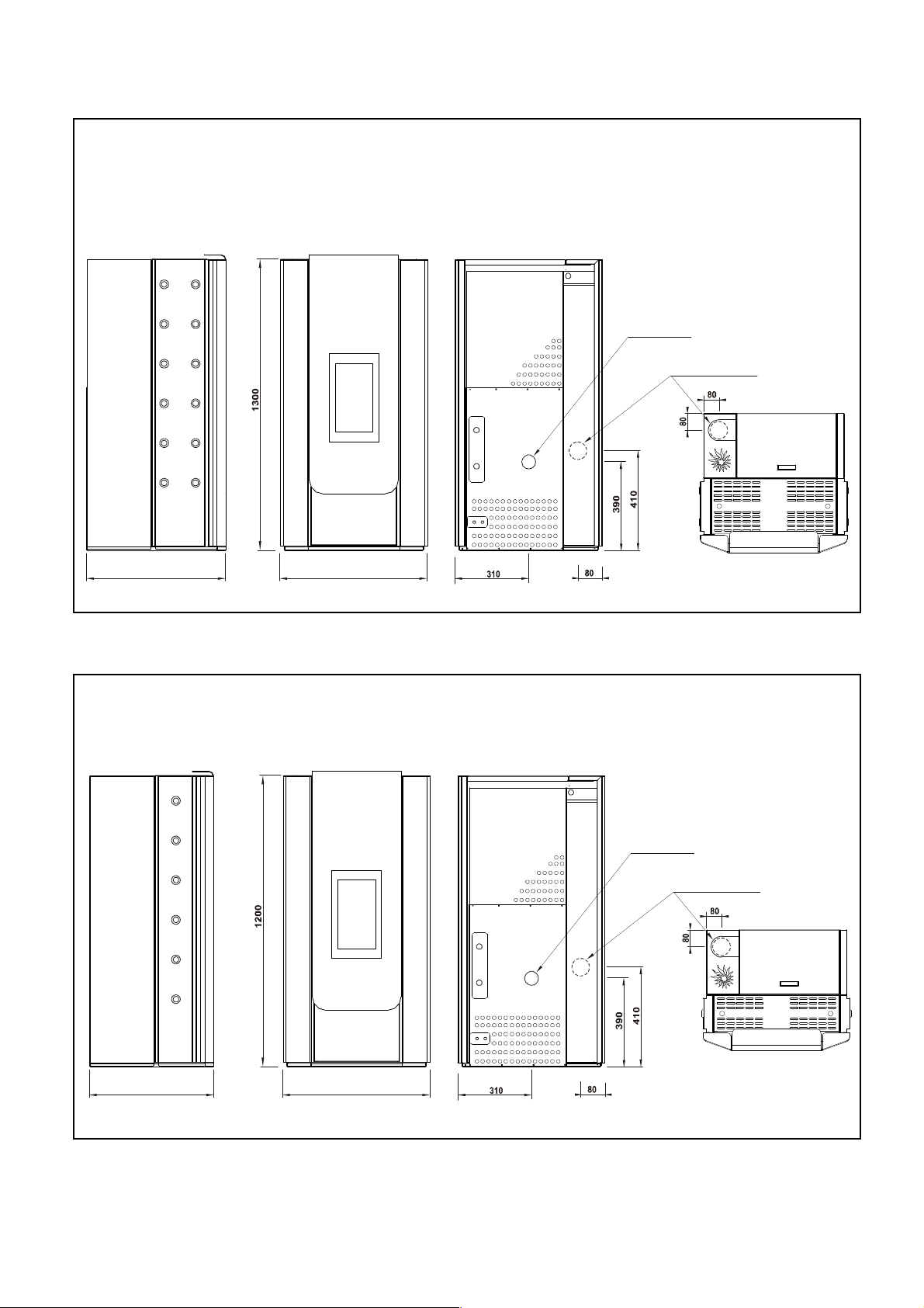
4. DIMENSIONS AND HYDRAULIC FITTINGS
SIDE VIEW
1- Automatic air vent
2- Smoke discharge Ø 80mm
3- Safety pressure switch
4- System return 3/4"
5- Boiler return 3/4"
6- Circulator
7- Safety valve discharge 3Bar
8- Boiler discharge cock
9- Expansion tank
10- System flow 3/4"
REAR VIEW
VENEXIA / MURANO 15-18
ENGLISH
4
630
620
scarico fumi
sortie fumées
presa aria esterna
external air intake
prise d’air extérieur
620
scarico fumi
sortie fumées
presa aria esterna
external air intake
prise d’air extérieur
EXTERNAL DIMENSIONS
VENEXIA 21-25 Model
VENEXIA 15-18 Model
output tube
output tube
ENGLISH
D.80mm
D.80mm
550
5

560
680
scarico fumi
sortie fumées
external air intake
prise d’air extérieur
HEAT INPUT
NOMINAL HEAT OUTPUT
POWER OUTPUT TO WATER
COMBUSTION EFFICIENCY (EN303-5)
CONSUMPTION AT FULL POWER
MURANO 15-18 Model
5. TECHNICAL DATA
presa aria esterna
output tube
ENGLISH
D.80mm
MAXIMUM SMOKE TEMPERATURE °C
AVERAGE OPERATING ELECTRICAL POWER W
MAXIMUM BOILER TEMPERATURE °C
MAXIMUM HOT WATER TEMPERATURE °C
MAXIMUM OPERATING PRESSURE bar
ENVIRONMENTAL QUALITY CLASS
MODEL
(wood pellet fuel)
(wood pellet fuel)
(wood pellet fuel)
(wood pellet fuel)
CO (13% O2) RATED POWER g/Nm3
CO (13% O2) REDUCED POWER g/Nm3
PP 13% O2 mg/Nm3
FUEL
(pellet fuel)
PELLET TANK CAPACITY Kg
HEATED VOLUME m3
SMOKE OUTLET DIAMETER mm
ELECTRICAL POWER SUPPLY V
MAXIMUM ABSORPTION A
MAXIMUM ELECTRICAL POWER W
BOILER WATER CAPACITY lt
BOILER NET WEIGHT kg
LOW VACUUM Pa
* The fire box, nominal power and the performance are measured by means of laboratory test in optimal installation conditions.
** The data has been taken from laboratory test in optimal conditions. The hourly consumption can vary depending on the type of pellet used and installation made.
*** The heated volume is subject to variation depending on the installation conditions, the type of insulation of the home and the outdoor climatic conditions relating
to the geographical position
UNIT OF
MEASURE
kW
kW
kW
%
kg/h
VENEXIA - MURANO 15 VENEXIA - MURANO 18 VENEXIA 21 VENEXIA 25
16,5* 18,4* 20,8* 25,6*
15,4* 17,0* 19,8* 24,0*
13,6* 15,3* 18,0* 22,1*
93,3* 92,5* 95,0* 93,4*
0,16 0,21 0,07 0,08
0,27 0,27 0,32 0,32
12,2 11,8 12,1 11,4
wood pellet - biomass wood pellet - biomass wood pellet - biomass wood pellet - biomass
21 21 32 32
180-430*** 180-470*** 300-540*** 300-640***
80 80 80 80
160 160 160 160
V230~ / 50Hz V230~ / 50Hz V230~ / 50Hz V230~ / 50Hz
3 3 3 3
130 130 130 130
700 700 700 700
80 80 80 80
65 65 65 65
3 3 3 3
32 32 52 52
4 stars 4 stars 5 stars 4 stars
220-250 220-250 270 270
6 6 6 6
4,4 max** 5,2 max**3,4 max** 3,8max**
6

Pf = pressione di taraura della valvola di sicurezza
coefficient
ENGLISH
6. HYDRAULIC CONNECTION
In order for the boiler to work correctly it must be suitably connected to a heating system. It is reminded that
installation must be carried out by trained personnel or companies according to MD 37/90. The
manufacturer declines any responsibility for installations not carried out correctly or by unqualified
personnel. For installation please refer to UNI7129 and UNI10412 (and any relative updates) Standards.
For a correct installation, verify that the hydraulic system is not leaking, thus jeopardising the functioning of the
generator and its integrity. In this regard, the installing company must adopt the solutions it considers
necessary in order to avoid that the thermal exchange surfaces of the boiler can, in time, suffer
limestone type incrustation, sludge, iron residues from the system and anything else foreign to the
heating water. This will enable optimising the thermal yield and functioning safety of the generator and
of the system. We strongly recommend installing a softener on the cold water inlet for system load and a mesh
filter on the boiler piping to the filter larger impurities.
COMPLETELY BLEED THE HEATING SYSTEM AND THE BOILER AT EVERY FILLING.
FROM IMPURITIES AND FERROUS PARTICLES.
ALTERNATIVELY, WE RECOMMEND YOU TO USE A HEAT EXCHANGER TO SEPARATE THE BOILER’S
WATER FROM THE CIRCUIT’S WATER.
If the production of domestic hot water is envisioned, installer a domestic boiler holding at least 80
litres for good boiler functioning.
The boiler is provided with an 8 litres expansion tank that, should it also be insufficient for the system, another
of adequate measure must be installed. Below is the calculation to determine the necessary capacity of the
expansion tank:
CONNECT THE SAFETY VALVE DRAIN AND BRING IT OUTSIDE THE BOILER.
A DIRT SEPARATOR WITH MAGNET MUST BE INSTALLED ON THE RETURN CIRCUIT TO
PROTECT THE BOILER’S INTERNAL COMPONENTS, AS THE ELECTRONIC CIRCULATOR,
INSTALL AN ANTI-CONDENSATION VALVE, WITH SETTING AT 55°C, AS CLOSE AS POSSIBLE
TO THE BOILER.
Ve=
Ce (Vi+Vc)
Pi
(1- )
Pf
Ve = volume expansion
Ve = volume espansione
Ce = expansion coefficient
Ce = coefficiente espansione
Vi = liters of water plant
Vi = litri di contenuto acqua impianto
Vc = liters of water boiler
Vc = litri di contenuto acqua caldaia
Pi = precharge pressure
Pi = pressione di precarica del vaso
Pf = pressure relief valve
COEFFICIENTE DI
Should the existing expansion tank be insufficient
provide an additional tank.
TEMPERATURA MAX
Max temperature
40
50
60
70
80
90
99
Expansion
ESPANSIONE
0,0076
0,0118
0,0168
0,0224
0,0287
0,0357
0,0432
7

CIRCUITO
RISCALDAMENTO
CALDA SANITARIA
CIRCUITO
RISCALDAMENTO
ENGLISH
CONNECTION LAYOUT
Connection to a heating system layout
HEATING SYSTEM
PUMP
CIRCOLATORE
COLLETTORE
CARICO IMPIANTO
Connection to a heating system and domestic hot water production layout
HEATING SYSTEM
PUMP
CIRCOLATORE
COLLETTORE
USCITA ACQUA
HOT WATER
OUTLET
CARICO IMPIANTO
DOMESTIC HOT
WATER TANK
COLD WATER
ENTRATA
INLET
ACQUEDOTTO
8

LEGEND OF SYMBOLS
HOT WATER DELIVERY
VALVE
ANTI-CONDENSATE
CIRCUITO
RISCALDAMENTO
CARICO IMPIANTO
CALDA SANITARIA
HOT WATER
ENGLISH
PUMP
CIRCOLATORE
HEATING SYSTEM
COLD WATER
ENTRATA
INLET
ACQUEDOTTO
USCITA ACQUA
OUTLET
PUFFER
STORAGE
MIN 300LT
VALVE
CHECK VALVE
PRESSURE REDUCER
SAFETY VALVE
THERMOMETER
EXPANSION
TANK
FILTER Y
SEPARATOR
WITH MAGNET
PRESSURE GAUGE
AIR VENT
BOILER DELIVERY
RETURN DELIVERY
HOT WATER RETURN
WATER SOFTENER
INSTALL AN ANTI-CONDENSATION VALVE, WITH SETTING AT 55°C, AS CLOSE AS POSSIBLE
TO THE BOILER.
INSTALL A THERMOSTATIC MIXER AT THE HOT SANITARY WATER EXIT.
INSTALL A SAFETY VALVE CALIBRATED AT 6 BAR AT THE COLD WATER INLET TO AVOID
ANY STRAIN OF THE SANITARY WATER TANK.
9
YES
ENGLISH
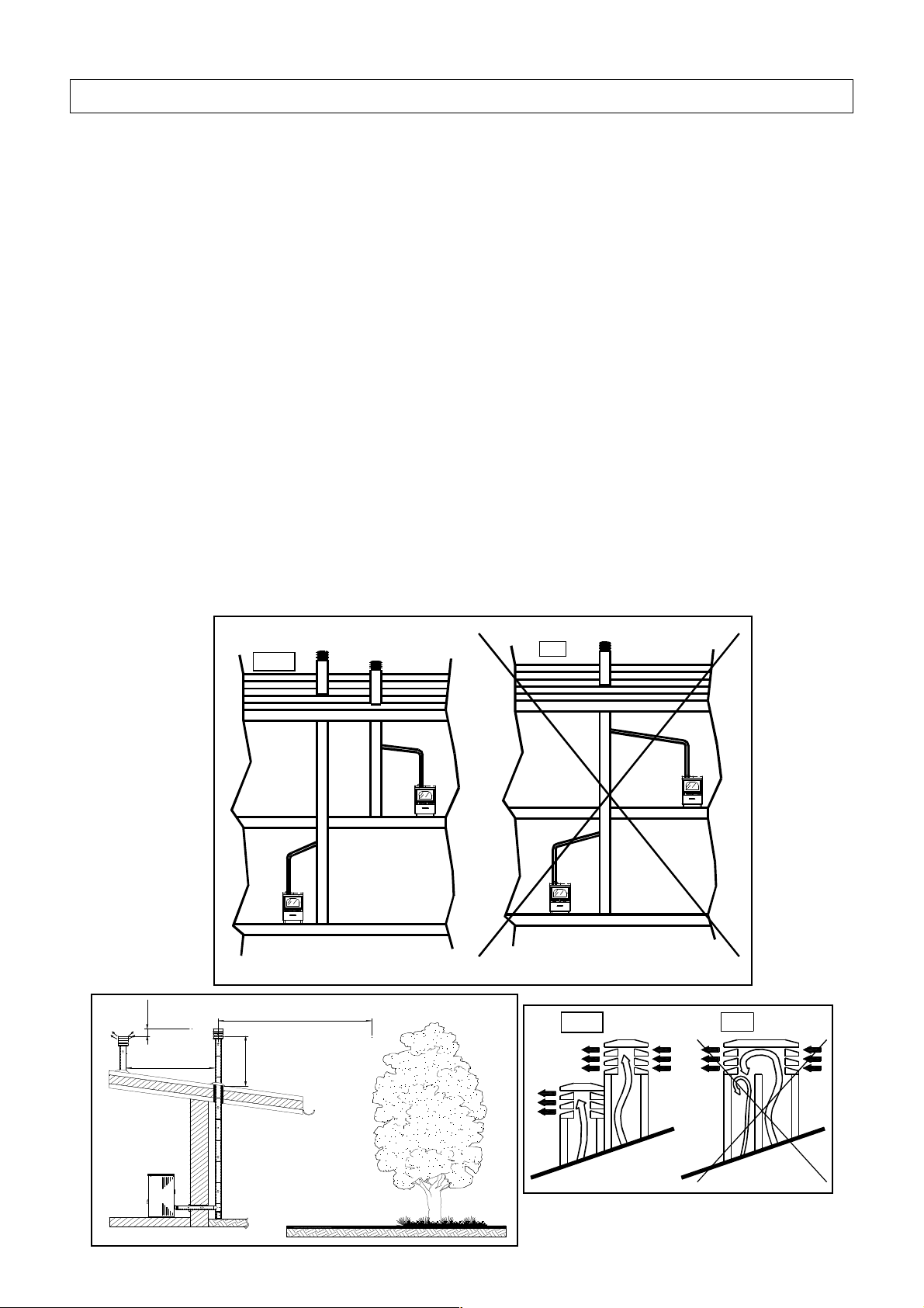
7. GENERAL RULES FOR CREATING THE FLUE
A few simple, yet important, rules to follow for safe constructing a flue are here explained (for further
information, please read the UNI 10683 regulation).
• Safe and correct pellet boiler operations depends on the connection to a single and independent flue. No
other fireplace, stove, boiler, aspiring hoods, etc., are to be connected to the same flue (see fig.3).
• This machine needs to expel products resulting from combustion via a vertical flue that has a suction
pressure between 6 and 8 Pa, in order to constantly guarantee the expulsion of smoke, even with the
absence of electric power or adverse conditions.
• The part of the flue that extrudes from the roof or remains in external contact must be covered with tiles or at
least well insulated.
• The stack must be wind resistant, with an internal section that is equal to that of the chimney, a useful
section at least twice the size of the chimney, and protect from any rain coming in.
• Any other building , plants or other obstacle that are higher than the roof must be positioned at least 3 m
away from the stack.(see fig.4).
• Whenever using two flues with parallel exits, raising the flue against the wind by one element is
recommended (see fig. 5).
The flue section must be uniform, with smooth walls that do not become more narrow, curves must be
regular and continuous.
It is advisable that the smoke conduct has a solid material and eventual condensation collecting box,
positioned under the smoke conduct intake, so that it is easily accessible and can be inspected from the
airtight door.
SI
NO
Fig.3
0,5 m
m in 2 m
m in 3 m
min 1,2m
Fig.4
YES
SI NO
Fig.5
10

ENGLISH
8. ELIMINATING FUMES DISCHARGE
Fumes discharge must comply with regulations in force and must therefore be brought above the roof. The
discharge tube must be made out of smooth steel with silicon washers and not be corrugated flexible type.
Furthermore it must be positioned externally and not in closed or semi-closed spaces. For example: garages,
narrow corridors, under closed roofs or any other place where fumes may collect in case of leaks. When
connecting the boiler to a flue, make sure, with a professional chimney sweep, that the flue is perfectly whole..
Oppositely it is absolutely obligatory to encase the existing flue with material which is suitable enough to ensure
correct functioning (see fig.7) The flue must not lean against the fan. It is necessary to assess the layout and
structure of the house once the flue has been installed via walls and the roof, to ensure that installation has
been done correctly and is in conformity with fire safety regulations. You should also check: the internal section
of the flue, that there are no obstructions or material used to build it, the height, the fittingness of the stack and
the possibility to realise vent holes.
TYPE OF TUBES USED FOR FLUES
Rigid painted steel tubes (at least 1.5 mm thick) , or stainless steel ones (at least 0.5 mm thick), can be used.
The male/female coupling collars must be superimposed by at least 40mm.
DIAMETER OF THE FLUE TUBE
The diameter of the tubes depends on the type of system. The boiler has been designed for tubes with an
80mm diameter, as shown in the table, however in some cases 100mm is advisable. If 100 mm diameter tubing
is necessary, connect it to the boiler using a "T" pipe connection using a ø 80 - ø 100 pipe fitting. (see fig. 8)
FLUE DIAMETER OPINION
Tube length less than 5 m 80 mm Correct
Tube length more than 5 m 100 mm (min) Mandatory
For installations at an altitude of more than
1200 m a.s.l.
Note: for each 90° curve add 1 m and for each 45° a dd ½ m. The lengths indicated on the table are only relevant for the vertical portion.
100 mm (min) Recommended
Horizontal parts must not exceed 2 m in length.
It is PROHIBITED to install air locks or valves that could obstruct the passage of smoke.
It is obligatory to use a "T" connection tube (see fig.8) with an inspection plug, as a connection between the
boiler and the flue, which will allow both the collection of soot that is deposited inside the tubes and periodical
cleaning of the flue, without the need to dismantle. Since the fumes are under light pressure, ensuring that the
plug for cleaning the flue is perfectly airtight is mandatory and it must be the same after each inspection. One
must remember put it back as it was originally and check the condition of the gasket. Verify that the various
tubes are connected properly, as instructed by the manufacturer.
It is strongly advised not to place tubes horizontally, but if absolutely necessary make sure they are placed with
an angle of at least 5%.
If a traditional flue is used it is possible to connect without the need for a "T" connection tube but you must
check that the flue has a bow for collecting ash.
It is advisable connect to the boiler with a horizontal track that is not more than 1m long.
If proper tube lengths are obeyed, the flue should have a draught between 6 and 8 Pa.
Do not change flue tube size in the middle of the route and especially after a bend or a horizontal portion. Verify
that there are no constrictions in the discharge conduit or in the flue.
11

Ø 100
DIREZIONE DI
ENGLISH
INSULATION AND DIAMETER OF HOLES IN WALLS OR ON THE ROOF
Once the position of the boiler is established and that you have checked that the place of installation is ideal, it
is then necessary to make the hole for passing tubes through the wall. This can vary according to the type of
installation, the diameter of the flue tube and the type of wall or roof that it must pass through.
N.B.: if the floor can not support the weight of the boiler, position a sheet platform of the correct size with
insulation applied on the floor (rock wool) and with a nominal density greater than 80kg/mc.
80-100 FITTING
Fig.7
END PART OF THE FLUE SYSTEM
The stack must not be installed in spaces that are closed, poorly ventilated or, in general, where fumes may
collect.
It is necessary to check that there are no flammable elements (plants, wood) or elements that could be visually
damaged (walls, windows) within 3m of the flue.
WARNING: Seeing that regulations regarding installation of pellet fuelled boilers are constantly being
updated, ask ones installer for eventual changes.
CLEANING
DIRECTION
Raccordo 80-100
Ø 80
“T” FITTING
Raccordo a "T"
PULIZIA
Fig.8
9. OXIDISING AIR INTAKE
Oxidising air can be taken from the atmosphere as long as there is sufficient ventilation, otherwise it is
necessary to take it from the outside: in this manner it is possible to guarantee an optimal combustion without
having to open air intakes in the room. For both cases please refer to the installation regulations in vigour (UNI
10683 and UNI7129) to avoid health risks of those who in the room where the machine has been installed.
Do not use flexible tubes and place a grid over the entrance (external) of the tube in order to stop alien
elements entering the system which could jeopardise the correct functioning.
12

MINIMUM DISTANCES FOR THE POSITIONING OF THE AIR INTAKE
For correct and safe positioning of the air intake (see
fig.9) where the minimum distances for any opening are
indicated. It is important to consider possible wall outlets
from other machines or kitchen aspiration hoods.
ENGLISH
Fig. 9
AIR INTAKE
10. ELECTRICAL CONNECTIONS
All machines are equipped with power cables, for which, in case of the need for replacing, an authorised
technician must be used.
Before connecting to the power supply, check that:
• the electric plant has been fitted with a 6A magnetothermal switch
• the characteristics of the plant are sufficient enough to satisfy what is indicated on the machine
characteristic plaque (electric power, nominal voltage etc...)
• that the plant has a sufficient earth connection according to nominal regulations in vigour (earth connection
is obligatory by law)
• the power cable should never. at any point, overheat 50°C above room temperature: If a direct connect ion is
desired, it is necessary to use an omnipolar switch, with a minimum opening between contacts of 3mm, that
has been designed for the electrical charge indicated on the plaque and must correspond to regulations in
vigour. the earth wire, brown/green, should not be interrupted by the switch. The plug or omnipolar switch
must be readily accessible once the machine has been installed
Disconnect the power supply when not using the machine for a prolonged period of time.
The manufacturer declines all responsibility if the above indicated anti-injury regulations are not
respected.
13

CIRCOL.
ELECTRONIC CONTROL BOX AND RELATIVE CONNECTIONS
IGNITION
POWER SUPPLY
230V - 50Hz~
RESISTOR
ACCEND.
N
L
FUSE
4 A
FUSE
0,8A
SMOKE FAN
ENCODER
CROG.
MISC.
COCLEA
CRUCIBLE
MOTOR
MIXING
AUGER
MOTOR
LOAD
AUGER
MOTOR
BOILER
SAFETY
THERMOSTAT
PORTA
P.H2OT.H2O
UNUSED
BOILER
PRESSURE
SWITCH
UNUSED
AUGER
SAFETY
THERMOSTAT
AIR PRESSURE
SWITCH
IF USING THE HOT DOMESTIC WATER BOILER CONNECT THE PROVIDED PROBE
CHECK THAT THE CONNECTION OF THE ROOM THERMOSTAT IS "CLEAN CONTACT" TO
AVOID DAMAGE TO ELECTRONIC CONTROL BOARD
DIVERTER
VALVE
N.C.
N.A.
ROOM
THERMOSTAT
BOILER
CIRCULATOR
DEV
PROGRAMMING
PORT
CALD.S.AMBT.AMBPRESST.SERT.COC
BOILER
PROBE
UNUSED
SANIT.
HOT WATER
PROBE
CLOCK
BATTERY
-T2+
UNUSED
-FUMI+
SMOKE
PROBE
CRUCIBLE
SENSOR MOTOR
COMBUSTION
FAN
FUMI
MSCCRG
MIXING AUGER
MOTOR SENSOR
ENGLISH
DISPLAY
14

ENGLISH
11. PRELIMINARY CONTROLS BEFORE THE FIRST START UP
N.B.: if the floor cannot support the weight of the boiler, position a correctly sized, at least 4mm thick,
sheet platform with insulation applied on the floor (rock wool) and with a nominal density greater than
80kg/mc.
MANDATORY GUIDE LINES FOR THE SAFETY OF PEOPLE; ANIMALS AND OBJECTS.
The following information is about a number of obligatory general regulations for a correct installation, and is
intended for the installer.
• It is recommended to place insulation between the floor and the touching points of the machine with a sheet
at least 2mm thick and a diameter at least 50mm greater than the area occupied by the machine, if the
boiler is installed on a wooden floor.
• The flue tubing must not have a diameter that is less than 80 mm.
• Leave a space of at least 50mm between the rear of the boiler and the rear wall, to ensure correct air intake
• Leave a space of at least 70cm around the sides of the boiler, to ensure easy maintenance.
• Should the machine be installed close to flammable or combustible walls, keep a safe distance of 30cm
from the rear and sides of the machine. Avoid leaving any type of flammable or combustible materials
within 1m of the heat waves from the glass window situated on the front of the machine.
• Check for a correct level of combustible load inside the crucible.
• Completely bleed the heating system before starting the boiler.
• Verify that the safety valve drain has been conveyed outside the boiler.
For the first few minutes that the machine operates (for the first time) it may be possible to smell
paint this is normal Aerate the room with the boiler operational.
MAKE A FLUE GAS OUTLET
Perform the following actions, as shown in the figures below:
- Connect an ash collector "T" tube to the exhaust motor (1)
- Install a 90 ° bend (2) to obtain the flue outlet on the rear side
- Install a straight tube (3), taking care to break the pre-cut on the top (4), to obtain the flue outlet on the upper side.
Flue gas outlet on the rear side Flue gas outlet on the upper side
4
3
2
1
15
1

Pause
Recorded boiler temperature
Recorded
domestic water
Operational power
ENGLISH
12. CONTROL PANEL DISPLAY
DESCRIPTION OF DISPLAY BUTTONS
SET
Set day and time
During operation
Key - turns the boiler on and off in manual mode (keep pressed for 2 sec.), eliminates alarms and exits
Lun 09:00 Tc 65°
OFF
Accesa 5 Ts 55°
programming.
Key SET - changes the screen and confirms set data
Key - key for increasing values being set
Key - key for decreasing values being set
MEANING OF LED LIGHTS
SUMMER
WINTER
The "permanently" on LED indicates the hot domestic water boiler is satisfied.
The "flashing" LED indicates the boiler is heating the hot domestic water boiler.
The "permanently" on LED indicates the heating system is not requesting heat.
The "flashing" LED indicates the heat request from the heating system.
13. OPERATIONAL PHASES
DISPLAY MEANING
Clean.
Charged
Pre-ventilation and safety controls phase, with fire pot cleaning before loading fuel.
Start-up phase with fuel load in the burner while supplying power to the resistors at the
same time.
Pause while awaiting flame.
St. fire
Stabil.
fire
Turn off
Off
Stand by
IN CASE OF AN ALARM, WAIT FOR THE END OF THE TURNING OFF PHASE
Waiting phase during which the start-up must take place.
Stabilisation phase, after the flame has started, with a medium size load of fuel.
Burner operational adjustment phase where power can varies from 1 to 6
Timed turn off phase associated to an interruption in the fuel for fire pot cleaning and
waiting for the flame to be totally extinguished.
Turned off status until there is an following request for heat
Switch-off for reached heating and domestic hot water temperature
16

combustible 1
ON00:00 OFF00:00
00:00
see specific
Load
Load
- _ _ _ 0 _ _ _ +
ENGLISH
14. PROGRAMMING
MAIN SETTINGS
Use the keys as instructed to access the desired setting
Lun 09:00 Tc 65°
OFF 5 Ts 55°
Season
ESC SET
Temp. boiler
ESC SET
Temp. hot water
ESC SET
Hours
ESC SET
Ignition
ESC SET
Combustible
ESC SET
ESC
ESC SET
Season
winter
Temperature H2O
boiler 70°
Temperature H2O
hot water 55°
Day of the
week Mon
Trigger
timer SI
Combustible
Using biomass fuels (maize, grape seed, other) it is important to mix them properly to ensure that the
boiler works correctly.
DO NOT EXCEED THE PERCENTAGE OF 60% OF CORN IN THE MIXTURE WITH WOOD PELLETS. Other
finely chopped fuels (for example: olive pits, shells, etc..) can be used alone, “not mixed” with wood
pellets, but they must have a minimum diameter of 4mm.
To correctly mix fuels it is recommended to weight them on scales with a precision of at least 100 g, and mix
them together in a single external container, not inside of the boiler, because that would not create an
homogenous mixture.
The menu “LOAD” allows to vary the quantity of combustible to be loaded and it is subdivided
into 3 levels of increase (+) and 3 levels of decrease (-): each level consists of 0,2 seconds,
therefore a total of +/- 0,6 seconds. Any variation made remains in permanent memory and it is
simultaneously programmed on all 6 power levels of the stove.
Before selecting on the display the type of fuel to be used make sure that it is the same as what is
already in the stove tank.
Hors
Timer01 mtwtfss
chapter
17

Timer02 mtwtfss
Timer02 mtwtfss
Timer02 mtwtfss
Timer02 MTWTFss
Timer02 MTWTFss
Timer02 MTWTFss
Timer02 MTWTFss
Timer02 MTWTFss
Timer02 MTWTFss
ON00:00 OFF00:00
ON00:00 OFF00:00
ON00:00 OFF00:00
ON00:00 OFF00:00
Press to modify
Press the key to confirm
Press the key to modify
Press the key to modify
ON08:30 OFF00:00
ON08:30 OFF00:00
AUTOMATIC START-UP PROGRAMMING
Turning off for each time slot must not terminate after 23:59 of that day
Activate
timer yes
Press to modify
Timer01 mtwtfss
ON00:00 OFF00:00
Press the key to confirm
Press to modify
ENGLISH
Press to modify
Press to modify
Press to modify
Press the key to confirm
ON00:00 OFF00:00
Press to modify
ON00:00 OFF00:00
Press the key to confirm
ON08:30 OFF00:00
Press the key to confirm
Press to modify
Press the key
18
Motor flue gas
ENGLISH
15. ALARM CODES
For your own safety do not tamper or modify any of the machine's components: the
manufacturer does not guarantee the normal operation, that as a result may be very dangerous.
In case of malfunctioning, difficulties, or whenever a safety device is activated, it is important to
contact authorised personnel. All operations must take place when the boiler is cold and disconnected
from the power supply.
DISPLAY MEANING
Non working fumes motor: contact an authorised technician
Auger motor 1
Crucible
1 heat.elem.KO One of the resistors is not working: contact an authorised technician
2 heat.elem.KO Both resistors are not working: contact an authorised technician
heat.element KO The resistors are continually supplied with power: contact an authorised technician
gas probe The fumes temperature probe is interrupted or disconnected: contact an authorised technician
room probe The room temperature probe is interrupted or disconnected: contact an authorised technician
Thermost. boiler
Thermostat auger
Pressure switch Air pressure regulator is not working: contact an authorised technician
system error Internal error of the electronic control box: turn stove off and restart it
The horizontal fuel loading auger is not turning: verify if the fuel tube is clogged or contact an
authorised technician
The burner fire pot does not rotate: clean the burner and restart or contact the authorised
technician
Intervention of the boiler safety thermostat: clean the inside of the stove, reset the thermostat
and restart the stove
Intervention on the part of the fuel auger safety thermostat: clean the inside of the stove, reset
the thermostat and restart the stove
black out Loss of electric power: clean the burner and restart
Failed ignition Failed start-up: clean the burner and restart
f. turn-off Flame turns off while operating: clean the burner and restart
Over heating gas Overheating of combustion fumes: clean the stove completely and restart.
Cont. operation Malfunctioning of pellet loading motor: contact an authorised technician.
Boiler probe Boiler temperature probe interrupted or disconnected: contact an authorised technician.
Hot water probe
H2O Pressure Hot water pressure below 0.5 bar: fill the system with water or call the authorised technician.
Filling
Pellet sensor One of the fuel level sensor does not work: call the technician.
service Stove maintenance warning: contact an authorised technician
Domestic hot water temperature probe interrupted or disconnected: contact an authorised
technician.
The filling of the fuel tank has not occurred within the pre-set time: check loading auger and fuel
availability. Call the authorised technician.
TO RESTORE BOILER FUNCTIONING KEEP THE KEY PRESSED FOR 3 SECONDS
19

ENGLISH
16. CLEANING AND MAINTENANCE
To ensure correct functioning and maximum efficiency of the boiler, carry out the following cleaning and
maintenance operations.
THE FOLLOWING OPERATIONS MUST BE PERFORMED WHEN THE BOILER IS COLD, AT LEAST ONCE A
WEEK AND WITHOUT ELECTRICAL POWER
BIOMASS BURNER
In order for the stove to work correctly it is important to keep the burner as clean as possible and free of any
combustion residue. At least once a week extract the flow nozzle by loosening the locking screw with the
supplied hex wrench (fig. A) and remove all of the ash and unburned residue inside the burner (fig. B) using the
flexible pipe supplied (fig. E) to connect to your vacuum cleaner. To remove any encrustation, scrape the inside
of the wheel holes (fig. C) with the tip of the supplied accessory (fig. F), remove and empty as well the
collecting container placed underneath the cast-iron wheel. Finally vacuum the air combustion duct (fig. D)
behind the burner. Having performed the cleaning, make sure to replace the front panel of the burner correctly,
screwing the locking screw until it’s limit stop.
Fig. A
Fig. D
ALWAYS KEEP THE HOLES OF THE ROTATING WHEEL CLEAN AND FREE OF ANY
COMBUSTION RESIDUE. THE CLEANING FREQUENCY HAS TO BE APPROPIATE TAKING
CARE TO THE WORKING HOUR OF THE MACHINE AND TO THE CHARACTERISTICS OF THE
COMBUSTIONS RESIDUE (HIGH PERCENTAGE OF ASHES OR PRESENCE OF DEPOSITS).
Fig. B
Fig. C
Fig. E
Fig. F
20

ENGLISH
ASHES DRAWER
Weekly switch-off the boiler and proceed as follows:
- Open the door under the hearth, unscrew the nut and remove the ashes drawer with care. Empty out all the
ash taking care that there are no hot ashes (fig. A).
- Carefully remove all ash from the bottom to avoid malfunctionings (fig. B).
- Place the ash drawer back into its place an tighten the wingnut until the gasket is fully in place.
FLUE GAS TUBE
At least once a week, remove the protection top panel and lift a few times the two cleaning levers on the sides
of the boiler (Fig. A), in such a way as to drop all the ash in the ash drawer below.
At this point remove the ash drawer, taking care to remove as well all of the ash on the bottom of the boiler and
above the cavity of the exhaust motor (Fig. B): to do this, connect the supplied flexible hose to your vacuum
cleaner.
Fig. A
N.B .: for the model Murano use the appropriate tool supplied.
HEARTH DOOR SEAL
Frequently check the conditions of the seal fastened along the internal border of the hearth door to ensure air
tight closing.
Note: verify seal hold by placing a sheet of paper between the closed door and the frame: when trying to
remove it, make sure that it is possible but difficult. If this is not the case, contact an authorised Service Centre
to have the seal replaced.
Fig. B Fig. A
Fig. B
21

ENGLISH
HEARTH DOOR GLASS
The glass mounted in the hearth door is ceramic, and therefore resistant to high temperatures. To clean, use a
non abrasive dry cloth with specific liquid for glass cleaning.
Should it be damaged (e.g. chipped) it is recommended to have it replaced immediately by an authorised
technician before starting up the machine
DO NOT attempt to repair damaged glass: as there is a risk of explosion during functioning!
FLUE
To ensure that the machine works well, at least once a week, open, and when needed, clean the "T" at the
base of the fumes conduit and the horizontal portion of tube, if there is one.
The vertical fumes conduit and the entire flue must be checked and cleaned at least once a year. We
recommend the use of a specialised technician for a thorough and professional cleaning.
COMBUSTION AIR INTAKE
Monthly inspect the air intake tube positioned under the start-up resistors to ensure it is not blocked by any
foreign material. If required, remove or suck out the dirt.
GENERAL END OF SEASON CLEANING
Every two months empty the pellet tank and clean out all accumulated saw dust.
After use, at the end of the season, clean and check all the parts indicated above, remembering to disconnect
the power supply of the boiler for increased safety.
It is advisable to check and clean the machine at least once per year by an authorised technician to ensure
correct functioning.
It is recommended, when required, to check lubrication of the fuel loading auger bronze bearings.
22
 Loading...