


INSTRUCTION MANUAL
Effective date:
30.09.2013
Digital Light Engraver DLE
ORIGINAL INSTRUC TION MAN UA L
CST GmbH
Königsberger Straße 117
47809 Krefeld - Germany
Telephone: +49 2151 1592260
Fax: +49 2151 520329
Email: support@c-s-t.de
office@c-s-t.de
CST GmbH
Königsberger Straße 117
47809 Krefeld - Germany
Page 1 of 69
Betriebsanleitung DLE-AF 01.0 engl.docx

INSTRUCTION MANUAL Digital Light Engraver
0
Contents
Effective date
30.09.2013
0.
0. Contents ....................................................................................................... 2
1. General Information ..................................................................................... 4
1.1 Notes about the Technical Annex .................................................................. 4
1.2 Explanation of symbols .................................................................................. 5
2. Safety ............................................................................................................ 7
2.1 Appropriate use and improper modes of ope r ati on ........................................ 7
2.2 General information for operators and personnel........................................... 9
2.2.1 Requirements placed on personnel ............................................................... 9
2.2.2 Operator’s duties............................................................................................ 9
2.2.3 Important rules of conduct ........................................................................... 10
2.3 Protective equipment ................................................................................... 12
2.3.1 Existing protective equipment ...................................................................... 13
2.3.2 Inspection of the protecti ve equipment ........................................................ 14
2.4 Emissions (noise levels/sounds) .................................................................. 15
2.5 Fire protection .............................................................................................. 15
2.6 Pneumatics .................................................................................................. 16
2.7 Hydraulics .................................................................................................... 16
2.8 Electrical ...................................................................................................... 17
2.9 Spare parts .................................................................................................. 17
2.10 Personal protective equipment .................................................................... 18
2.11 EC DECLARATION OF CONFORMITY ...................................................... 19
3. Transportation, storage, installation, electrical connection .................. 20
3.1 Special safety instructions ........................................................................... 20
3.2 Transport ..................................................................................................... 21
3.3 Storage ........................................................................................................ 22
3.4 Installation .................................................................................................... 23
3.5 Electrical connection .................................................................................... 23
4. Machine description .................................................................................. 24
4.1 Machine housing .......................................................................................... 25
4.2 Screen frame clamping system .................................................................... 26
4.3 Bridge .......................................................................................................... 27
4.4 Operating control units ................................................................................. 28
5. Initial commissioning, decommissioning ................................................ 30
5.1 Special safety instructions ........................................................................... 30
5.2 Preparatory work for commissioning ............................................................ 32
5.3 Decommissioning ......................................................................................... 33
5.4 Instructions about disposal .......................................................................... 34
6. Operation and cleaning ............................................................................. 35
6.1 Special safety instructions ........................................................................... 35
6.2 Operation ..................................................................................................... 37
6.2.1 Starting the machine .................................................................................... 37
6.2.2 Start an imaging process ............................................................................. 38
6.2.3 Four colour printing ...................................................................................... 41
CST GmbH
Königsberger Straße 117
47809 Krefeld - Germany
Page 2 of 69
Betriebsanleitung DLE-AF 01.0 engl.docx

INSTRUCTION MANUAL Digital Light Engraver
0
Contents
Effective date
30.09.2013
6.2.4 Checking the LEDs ...................................................................................... 42
6.2.5 Finishing work on the machine .................................................................... 43
6.2.6 EMERGENCY STOP ................................................................................... 44
6.2.7 Action to be taken after an EMERGENCY STOP ........................................ 44
6.2.8 DLE settings ................................................................................................ 45
6.3 Focus test for the DLE Engraver .................................................................. 49
6.4 Cleaning ....................................................................................................... 53
7. Dealing with faults ..................................................................................... 56
8. Service and Maintenance .......................................................................... 61
8.1 Special safety instructions ........................................................................... 61
8.2 General ........................................................................................................ 64
8.3 Weekly/monthly intervals ............................................................................. 65
8.4 Biannual/ annual interval .............................................................................. 65
8.5 Maintenance plan......................................................................................... 67
8.6 Maintenance Logbook .................................................................................. 68
9. Technical Annex ........................................................................................ 69
CST GmbH
Königsberger Straße 117
47809 Krefeld - Germany
Page 3 of 69
Betriebsanleitung DLE-AF 01.0 engl.docx

INSTRUCTION MANUAL Digital Light Engraver
1
General Information
Effective date
30.09.2013
1. General Information
This instruction manual provides a wealth of safety and operating instructions
for the following product:
Vertical Digital Light Engraver (DLE)
1.1 Notes about the Technical Annex
The Technical Annex is an integral part of this instruction manual and includes all important technical details agreed upon
between the purchaser
and the manufacturer, including, for example:
• Project technical drawings/data sheets
• Spare parts list for parts subject to wear
• Relevant operating instructions
• Information pertaining to the necessary certification
• Miscellaneous
Apart from the basic model, we also offer optional extras and a variety of
configurations.
Options include:
• A semi-automatic unloading system for the machine in cooperation with
other vendors
• A fully automatic loading and unloading system in cooperation with other
vendors
• Customer-specific adaptation.
This instruction manual contains important information that needs to be taken
into account in all stages of the life cycle of the machine, including the transportation, installation, operation, maintenance and disposal.
Therefore, it is imperative that this instruction manual is read by the installation engineer and the responsible technical personnel/operator prior to installation and commissioning and must always be stored at the operating location of the machine.
Information pertaining to
specific hazards to persons, property or the envi-
ronment is highlighted in the relevant chapters of this instruction manual.
Apart from this instruction manual, it is important to take into account th e rel-
evant technical documentation provided by the vendors. This contains the
operational safety instructions which have to be observed.
CST GmbH
Königsberger Straße 117
47809 Krefeld - Germany
Page 4 of 69
Betriebsanleitung DLE-AF 01.0 engl.docx

INSTRUCTION MANUAL Digital Light Engraver
1
General Information
Effective date
30.09.2013
1.2 Explanation of symbols
Danger
Nature and source of hazard!
This symbol warns of an immediate danger to the life and health of people.
• Failure to observe such instructions could lead to severe adverse health
effects or even life-threatening injuries as well as substantial dam age to
property.
• Action that has to be avoided to prevent hazards from arising.
Warning
Nature and source of hazard!
This symbol warns of a possible dangerous situation to the lif e and health of
people as well as damage to the environment and property.
• Failure to observe such instructions could lead to severe adverse health
effects to lif e-threatening injuries as well as substantial damage the environment and property.
• Action that has to be avoided to prevent hazards from arising.
Caution
Nature and source of hazard!
This symbol warns of a possible dangerous situation to the life and health of
people as well as damage to the environment and property.
• Failure to observe such instructions could result in moderate
to slight
health effects or even injuries as well as damage to the environment and
property.
• Action that has to be avoided to prevent hazards from arising
Information
Nature and source of hazard to the machine and equipment!
This symbol warns of a hazardous situation and indicates important instructions on how to handle the machine and the equipment.
• Failure to observe such instructions can lead to extensive damage to
property.
• Action that has to be avoided to prevent
damage to the machine and
equipment.
CST GmbH
Königsberger Straße 117
47809 Krefeld - Germany
Page 5 of 69
Betriebsanleitung DLE-AF 01.0 engl.docx

INSTRUCTION MANUAL Digital Light Engraver
1
General Information
Effective date
30.09.2013
Warning symbol denoting
remotely started equipment
Warning symbol denoting
drawing-in hazard
Caution, warning symbol denoting a danger zone
Warning symbol denoting
bottleneck
Warning symbol denoting a
slip hazard
Warning symbol denoting
fork lift trucks in operation
Warning symbol denoting
hazardous voltage
Warning symbol denoting UV
radiation
Warning symbol denoting hot
surface
Warning symbol denoting
suspended load
Warning symbol denoting
hand injury
Always wear protective safety glasses against UV radiation
Please follow these instructions and act accordingly in all cases.
Instruct all other users in regard to these safety guidelines.
CST GmbH
Königsberger Straße 117
47809 Krefeld - Germany
Page 6 of 69
Betriebsanleitung DLE-AF 01.0 engl.docx

INSTRUCTION MANUAL Digital Light Engraver
2
Safety
Effective date
30.09.2013
2. Safety
2.1 Appropriate use and improper modes of operation
Information
Improper operation could lead to damage to the machine and equipment!
Improper operation can lead to damage to the machine and equipment.
• Make sure that all operations are carried out by qualified, authorized and
trained personnel.
• Follow the instructions given in the manufacturer’s instruction manual
carefully and comply with them accordingly.
• Make sure that the workplaces are clean when the machine and equip-
ment are in operation.
• Do not place any tools, appliances or the like on the machine and equip-
ment.
• Do not operate the machine and equipm ent without having prior adequate
training or without having first read the manufacturer’s instruction manual.
• Do not operate the machine and equipment with products that are not in-
tended to be used with the machine and equipment.
• Ensure that there is sufficient lightning when the machine and equipment
are in operation.
• Do not climb on or through the machine and equipment.
The CST Digital Lig ht Engraver is intended to be used in the print industry for
imaging screen stencils.
The machine is designed to be used only in the field of application listed in
the Technical Information section of the order confirmation or in this manual.
Any changes to the operating conditions shall necessitate a new contractual
agreement.
The machine shall be exclusively used in such a way as is desc ribed in the
order confirmation. Any other or additional operation, including, for example,
processing other products or operating with a mesh on the screen stencil that
is not intended for the process, shall be deemed improper usage.
The manufacturer/vendor shall not be held liable for any damage that results
from this. The risk is borne solely by the user.
The warranty and liability shall be in accordance with the contractual terms
and conditions.
CST GmbH
Königsberger Straße 117
47809 Krefeld - Germany
Page 7 of 69
Betriebsanleitung DLE-AF 01.0 engl.docx

INSTRUCTION MANUAL Digital Light Engraver
2
Safety
Effective date
30.09.2013
The machine and equipment shall only be operated with correctly installed
safety devices.
We would like to explicitly point out that no safety devices should be removed or disabled while the machine and equipment are in operation.
When maintenance work and cleaning as well as maintenance and repair
services are being performed, the machine and equipment shall be secured in such a way as to preclude unauthorized or inadvertent switching
on of the machine and equipment.
When t he maintenance and repair work as well as service work for overhauling and carrying out repairs are complete, all safety systems shall be
fully reinstalled and made operative again. An expert should check the
systems to make sure they function correctly.
When a member of staff recognises that there exists t he immediate risk of
danger to people at the machine and equipment
, the EMERGENCY
STOP device on the machine and equipment must be activated immediately.
In such cases of damage that would cause an immediate shutdown of the
machine and equipment, an EMERGENCY STOP device on the machine
and equipment can also be activated or automatically triggered.
The EMERGENCY STOP device should never be used to shut down the
machine and equipment under normal working conditions.
Special attention must be given to mounting and removing screen frames
and screens on the machine and equipment as it has to be carried out
carefully.
If work is carried out in an inattentive or careless manner, there exists the
hazard of limbs, items of clothing and objects being crushed, impacted
and sheared, which is due to moving parts. Therefore, particular attention
needs to be paid to the following points:
• Do not reach into the open gaps between the screen frame and bridge
• Extreme caution is needed when the bridge is in motion
• Apart from exceptional cases, screen frames are only to be inserted when
the machine and equipment are not in operation
• Tight fitting safety clothing and gloves should be worn
• Please exercise caution with lighting units and motors as they can be-
come very hot! Do not touch the lighting units and motors with exposed
limbs. Depending on the temperature of the lighting units, being in close
proximity to the lighting units can lead to burns
• Do not change the specific purpose of the machine
• During the manufacture of this product, the safety devices were specially
designed to wor k with this machine
• Please consult CST GmbH if you intend to change the intended use of the
machine
• Please make sure that the operators are familiar with the operation of the
machine and equipment
CST GmbH
Königsberger Straße 117
47809 Krefeld - Germany
Page 8 of 69
Betriebsanleitung DLE-AF 01.0 engl.docx

INSTRUCTION MANUAL Digital Light Engraver
2
Safety
Effective date
30.09.2013
2.2 General information for operators and personnel
Prior to commencing work, the personnel designated to use
the machine
must be instructed on the hazards relating to their work and the m easures
used to prevent such hazards. Such instructions shall be derived from this
instruction manual.
The instruction manual and the applicable regulations should be stored in
such a way that they are accessible to operators and maintenance staff.
Disregarding the safety instructions can adversely affect the safety of both
the personnel and the environment as well as the machines. Disregarding
the safety instructions can also lead to the forfeiture of all c la im s a gainst war-
ranty.
In detail, disregarding the safety instructions could result in the following
hazards:
• Failure of important functions of the machine
• Failure of specified procedures of maintenance and repair
• Exposure of people to electrical, mechanical, physical and chemical
hazards
2.2.1 Obligation of the personnel
All work on/with the machine shall be carried out only by personnel who, by
virtue of their training and qualifications, are authorised to do so.
Responsibilities, competence and supervision of the personnel
must be
clearly defined by the operator.
Task
Qualification
Connection and installation operations Trained personnel
Qualified personnel from the
manufacturer
Repair, maintenance, inspection
Loading, supervision Trained personnel
Electrical work Qualified electrician
2.2.2 Operator’s duties
The operator is obliged to operate the machine onl y in perfect working condition.
The operating personnel must be ass igned by the operator to oper ate the m achine.
CST GmbH
Königsberger Straße 117
47809 Krefeld - Germany
Page 9 of 69
Betriebsanleitung DLE-AF 01.0 engl.docx

INSTRUCTION MANUAL Digital Light Engraver
2
Safety
Effective date
30.09.2013
In particular, the operator’s area of responsibility includes:
• Assigning trained and instructed personnel,
• Defining the responsibilities for operation, set up, maintenance, and re-
pairs,
• Making regular checks on
the operating personnel in regard to potential
hazards and making sure they work in a risk-aware manner in accordance
with this instructions manual
The operator is to safeguard against any possible danger zones which may
arise bet ween this machine and any upstream or downstream devices that
have been provided by the customer.
If the Digital Light Engraver is to be integrated into an
interlinked machine
line/machine, the provisions of the European Directives with regard to the
major modifications made to the mac hine have to be observed, if applicable.
The operator is legally obliged (irrespective of the operational state or asdelivered state of the machine) to assess the hazards that may arise out of
the employees work and to determine
any occupational safety measures that
may be required.
The operator is responsible for the observance of the relevant regulations.
2.2.3 Important rules of conduct
Danger
Increased risk of accidents as a result of moving masses!
The movement of masses can lead to serious/fatal injuries.
• People who operate power-driven machinery must make sure that they do
not endanger themselves or others through hazardous motions
• Access to the interior of the machine housing is only permitted when the
machine has been switched off and measures have been taken to pr event
it from being inadvertently switched back on
• Long hair, loose clothing, jewellery or the like can be drawn into moving
parts. This can lead to serious injury.
• Wear t ight-fitting clothing. Long hair can be protected by wearing a hair
net. Remove jewellery.
• It is not permitted to climb on the machine while it is in operation.
Danger
Increased risk of accidents as a result of partly intense/high levels of
ultraviolet radiation!
When monitoring/checking the ultraviolet light, there is always the risk of serious eye injuries and even permanent eye damage.
Wear appropriate protective equipment in the form of safety glasses that are
suitable for the particular light source.
• Never look directly at the ultraviolet beam or the image of the pattern on
the screen to be imaged without personal protective equipment (safety
glasses).
CST GmbH
Königsberger Straße 117
47809 Krefeld - Germany
Page 10 of 69
Betriebsanleitung DLE-AF 01.0 engl.docx

INSTRUCTION MANUAL Digital Light Engraver
2
Safety
Effective date
30.09.2013
For the protection of the operators, warning and danger signs are placed on
the machine. Please observe these signs and act with extreme caution.
Additionally placed instructions must be strictly observed.
If warning and danger signs are damaged or illegible, they shall be replaced
immediately!
In addition to the instructions given in this manual, existing national accident
prevention rules as well as generally applicable legal and other mandatory
regulations relevant to accident prevention and environmental protection
must be observed!
Danger
Injuries and fatal accidents can occur as a result of hazardous voltage!
If there is a fault with electrical components or cables, the direct or indirect
contact with live parts could result in serious or fatal injury by electric shock.
• Replace faulty electrical cables and components immediately.
• Do not touch any components or cables that may be electrically live.
Warning
Adverse health effects due to the coolant used in machine!
The coolant contains 1.2-Ethanediol. The following precautions are recommended by the manufacturer/supplier of the heat transfer concentrate:
• R22: Harmful if swallowed.
• S2: Keep out of the reach of children.
• S24/25: Avoid contact with skin! In case of contact with skin, rinse imme-
diately with plenty of water.
• S46: If swallowed, seek medical advice immediately and show the con-
tainer or label.
• Not a hazardous material in compliance with GGVS
(ordinance on the
transport of dangerous goods by road) and GGVE
(ordinance on the
transport of dangerous goods by rail)
• Processing instructions of the manufacturer/vendor must be observed
Before working on electrical equipment, the entire machine must be disconnected from the mains. This is achieved by switching off t he main switch and,
if necessary, isolat ing it from the power supply (disconnect the power supply
plug).
Work on electrical installations shall only be undertaken by qualified electricians and in accordance with the applicable rules of electrical engineering.
Fuses may not be repaired or bypassed. Only u
se fuses specified by the
manufacturer.
CST GmbH
Königsberger Straße 117
47809 Krefeld - Germany
Page 11 of 69
Betriebsanleitung DLE-AF 01.0 engl.docx

INSTRUCTION MANUAL Digital Light Engraver
2
Safety
Effective date
30.09.2013
2.3 Protective equipment
Danger
Injuries and fatal accidents can occur as a result of missing protective
equipment!
If protective equipment is missing, damaged and/or modified there exists the
risk of injuries and fatal accidents.
• The machine and equipment may only be operated when all protective
equipment is in place and full working order.
• Do not remove or modify any protective equipment.
Operators and users are responsible for operating the machine in the correct
manner!
Danger zones that cannot be eliminated by constructional measures are fitted with protective equipment and, where appropriate, the machine is marked
with warning signs; moreover, relevant information relating to safe working
practice is specified in the instruction manual.
No alterations, additions or modifications that could affect safety are to be
made to the machine.
CST GmbH
Königsberger Straße 117
47809 Krefeld - Germany
Page 12 of 69
Betriebsanleitung DLE-AF 01.0 engl.docx

INSTRUCTION MANUAL Digital Light Engraver
2
Safety
Effective date
30.09.2013
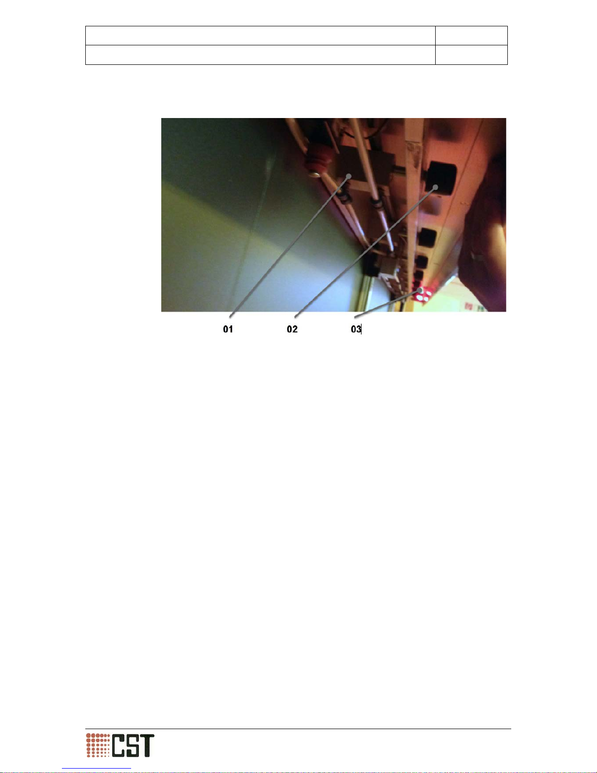
2.3.1 Existing protective equipment
The machine is equipped with the following safety devices:
• The lockable main switch is located on the main control panel (01).
• An EMERGENCY STOP button (02) is located on the vertical protect ive
cover (03) of the traversing head unit.
• A protective cover (03) covers the traversing head unit.
• Warning and information signs (04) indicate possible danger zones.
CST GmbH
Königsberger Straße 117
47809 Krefeld - Germany
Page 13 of 69
Betriebsanleitung DLE-AF 01.0 engl.docx

INSTRUCTION MANUAL Digital Light Engraver
2
Safety
Effective date
30.09.2013
2.3.2 Inspection of the protective devices
Planning, execution and documentation pertaining to the inspection shall be
carried out by the operator and shall take into consideration the applicable
laws and regulations. The following information specifies some of the criteria
and proposals.
Main Power Switc h and EMERGENCY STOP button
Intervals
When the machine is switched on as well as every 4 years
in the scope of the electrical test in accordance with the r egulations of the Employer's
Liability Insurance Association
[BGV A3]
Scope
Functionality
Inspector
Operating personnel
Action to be
taken when
faults occur
• Do not switch on the machine
• Disconnect from the mains supply
• Arrange for qualified electrician to carry out maintenance
Protective cover
Intervals
When the machine is switched and before it is opened
Scope
Functionality (the machine must switch off when the protective cover is opened.)
Inspector
Operating personnel
Action to be
taken when
faults occur
• Do not switch on the machine
• Disconnect from the mains
• Arrange for qualified electrician to carry out maintenance
Protective guard (cover)
Intervals
During the commissioning and when the machine is
switched on
Scope
Visual inspection of the physical integrity
Inspector
Operating personnel
Action to be
taken when
faults occur
• Close off the danger zone
• Carry out repairs
CST GmbH
Königsberger Straße 117
47809 Krefeld - Germany
Page 14 of 69
Betriebsanleitung DLE-AF 01.0 engl.docx

INSTRUCTION MANUAL Digital Light Engraver
2
Safety
Effective date
30.09.2013
2.4 Emissions (noise levels/sounds)
Sound emissions are inevitable with machines and equipment in operation.
These emissions are within the stipulated limits.
However, the on-site sound pressure level can vary. This depends upon the
operating conditions, such as the number of machines and equipment in the
room, external noise, and the design of the production area.
If this is the case, the operator of the machine or system must provide appropriate protection for the operating personnel. The noise protection devices
must not be removed from the machine or equipment.
All personnel who work on the machine or equipment must wear the specified personal hearing protection.
Advice for when to wear personal hearing protection:
• Up to 70 dB (A):
In this case, no special measures are required
. People’s sensitivity to
noise varies. Therefore, people who feel that they are bothered or even
harmed by such noise should wear hearing protection
• From 80 dB (A):
People constantly working in this particular area should wear hearing protection
• From 85 dB (A): Hazardous noise area
Such areas must be marked with warning signs. People working in these
areas must wear hearing protection
2.5 Fire protection
The local fire protection regulations are to be observed.
Avoid naked flames, extreme heat and sparks when using cleaning agents,
flammable or deformable parts in the vicinity of the machine. Failur e to comply could result in a fire; this may result in harmful gases or damage to the
insulation.
CST GmbH
Königsberger Straße 117
47809 Krefeld - Germany
Page 15 of 69
Betriebsanleitung DLE-AF 01.0 engl.docx

INSTRUCTION MANUAL Digital Light Engraver
2
Safety
Effective date
30.09.2013
2.6 Pneumatics
Any work to be carried out on the pneumatic systems of the machine or
equipment shall only be undertaken by a pneumatic system specialist.
Prior to working on pneumatic equipment, the moving parts of the pneumatic
system are to be placed in their home or park position.
Depressurise the
pneumatic system before performing any work on i t.
Caution is needed when looking for leaks in pneumatic lines that are under
pressure. Pressurized air can penetrate clothing and sk in, which can result in
injury or severe infections.
Caution is needed when loosening or replacing pneumatic lines; incorrectly
connected pneumatic lines can result in operations not functioning correctly.
The movement area of the actuator should not be blocked and acces s to the
area of movement of the actuator must be sufficiently secured.
2.7 Hydraulics
Any work
to be carried out on the hydraulic systems of the machine or
equipment shall only be undertaken by a hydraulic system specialist.
Prior to working on hydraulic equipment, the moving parts of t he pneumatic
system are to be placed in their home or park position. Depressurise t he hydraulic system before performing any work upon it.
Caution is needed when looking for leaks in hydraulic lines that are under
pressure. Pressurized hydraulic fluid can penetrate clothing and skin, which
can result in injury or severe infections.
Caution is needed when loosening or replacing hydraulic lines; incorrectly
connected hydraulic lines can result in operations not functioning correctly.
The movement area of the actuator should not be blocked and acces s to the
area of movement of the actuator must be sufficiently secured.
CST GmbH
Königsberger Straße 117
47809 Krefeld - Germany
Page 16 of 69
Betriebsanleitung DLE-AF 01.0 engl.docx

INSTRUCTION MANUAL Digital Light Engraver
2
Safety
Effective date
30.09.2013
2.8 Electrical
Before the machine and equipment is commissioned, all connections and
connected loads must be checked. The values that are measured must correspond to those specified on the electrical circuit diagram.
When the main switch is turned off the machine and equipment are isolated.
Nevertheless, inside the cabinets there could still be voltage-carrying parts,
such as power supplies for the interior lighting and service electrical sockets,
and these need to be switched off separately.
Before any work can be started on the electrical equipment, the m achine or
equipment have to be checked if the power is switched off, and, if necessary,
earthed and short circuited. Suitable insulated tools, safety equipment and
personal protective equipment must be used and tested every time before
being used.
Before disconnecting and connecting any electrical plug connections, make
sure they are isolated (this is with the exception of network connections, a s
long as they have non-hazardous voltages which satisfy the safety regulations).
Electrical parts (such as motors), which have been stored for a long time,
should not be used until they have undergone prior isolation tests.
When electrical equipment parts or components have become wet, some
parts, which would normally be voltage free in a dry condition, could be live.
Before touching a component that has become damp or wet, please check,
by means of a measurement, if exposed components have a voltage.
Faulty fuses must not be repaired or bypassed and are to be replaced by a
fuse of the same type.
2.9 Spare parts
You should only use genuine parts that are specified by us.
When you don’t use original components, or spare
parts that were neither
supplied by us nor were tested and approved by us, they could impair the
safety.
We will not be held liable for damage that is caused by such items.
For the erection, installation, integration as well as services for maintenance
and repair work, or alterations to machinery and equipment, our experienced
service technicians are available.
All details about contacting CST GmbH can be found on the cover of the operator handbook.
CST GmbH
Königsberger Straße 117
47809 Krefeld - Germany
Page 17 of 69
Betriebsanleitung DLE-AF 01.0 engl.docx

INSTRUCTION MANUAL Digital Light Engraver
2
Safety
Effective date
30.09.2013
2.10 Personal protective equipment
The type and extent of per sonal protective equipment required shall be defined by the operator in the scope of the risk assessment (see 2.2). The fol-
lowing information specifies some of the criteria and proposals.
Head
Not required in normal operation. Adjust appropriately to surroundings.
The minimum protection required are industrial hard hats conforming to DI N
en 812 which is recommended for maintenance work (ref er to Occupational
Health and Safety Regulations of the Trade A
ssociations regulation 193
[BGR 193])
Eyes
For exposure to hazardous
ultraviolet (UV) radiation: tight fitting protective
safety glasses with side protection (refer to Occupational Health and Safety
Regulations of the Trade Associations regulation 192 [BGR 192])
Body
Not required in normal operation. Adjust appropriately to surroundings.
Ears
Not required. Adjust appropriately to surroundings.
Hands
When there is the danger of a hot surface:
suitable protective gloves (e.g.
protective gloves in respect of mechanical hazards, in accordance with EN
388, category 1, also refer to Occupational Health and Safety Regulations of
the Trade Associations regulation 195 [BGR 195]).
Feet
Protective shoes classified S1 or P1 or professional shoes classified P1 are
required.
For maintenance work: safety boots
Please observe the hygiene rules when using personal protective equipment
and work clothes!
CST GmbH
Königsberger Straße 117
47809 Krefeld - Germany
Page 18 of 69
Betriebsanleitung DLE-AF 01.0 engl.docx

INSTRUCTION MANUAL Digital Light Engraver
2
Safety
Effective date
30.09.2013
2.11 EC DECLARATION OF CONFORMITY
CST GmbH
Königsberger Straße 117
47809 Krefeld - Germany
Page 19 of 69
Betriebsanleitung DLE-AF 01.0 engl.docx

INSTRUCTION MANUAL Digital Light Engraver
3
Transportation, storage, installation, electrical
connection
Effective date
30.09.2013
3. Transportation, stora ge , installation, electrical connection
3.1 Special safety instructions
Danger
Serious or even fatal injury can occur during transportation, storage,
installation and electrical connection!
Disregarding the safety instructions can lead to injuries and fatal accidents.
• Please observe the safety information given in the chapter entitled
"Safety
" as well as the appropriate on-site applicable safety and accident
prevention regulations.
• All lifting and transportation work should be undertaken by qualified and
trained personnel and those who have been assigned to do such work.
• When permitted only use appropriate safety equipment, such as secure
ladders, lifting truck or the like to secure the means of transport (such as
transport crates).
• Do not climb on the means of
transport, unless it has been expressly
permitted.
Danger
Injuries and fatal accidents can occur as a result of the improper handling of loads!
The improper handling of loads can lead to injuries or fatal accidents as well
as the hazard of damage to the machine and equipment.
• Secure the load before any lifting and transport work is to be undertaken.
• Use cranes, hoists, lifting devices, slings and lifting tackle,
which are in
accordance with the applicable on-
site safety and accident prevention
regulations, and are designed for the weight of the machine and equipment.
• Use cranes, hoists, lifting devices, slings and lifting tackle which are speci-
fied by the manufacturer. Relevant approvals must be submitted (e.g.,
driving permits for cranes).
• All cranes, hoists, lifting devices, slings and lifting tackle m ust be regular ly
checked and keep a record of this in the inspection logbooks.
• Only use the designated lifting points for lifting the load.
•
Wear the appropriate protective equipment (e.g. gloves, safety boots,
hard hat, etc.).
• When undertaking any lifting or transportation work please exercise due
care and attention.
• Check that there are no personnel in the immediate lifting or transporta-
tion area and mak e sur e that the lifting or transportation area is cordoned
off
• Do not reach underneath or between suspended loads.
• Do not walk under suspended loads.
CST GmbH
Königsberger Straße 117
47809 Krefeld - Germany
Page 20 of 69
Betriebsanleitung DLE-AF 01.0 engl.docx

INSTRUCTION MANUAL Digital Light Engraver
3
Transportation, storage, installation, electrical
connection
Effective date
30.09.2013
3.2 Transport
Please refer to the order/delivery documentation f
or the exact scope of the
delivery. Following the delivery of the machine and all accessories, any damage caused by def ective packaging or transport shall be reported to the forwarder, the insurance company and the manufacturer
. Furthermore, we
would like to draw your attention to our Terms of Sale and Delivery.
Information
The improper handling of loads can lead to damage to the machine and
equipment!
The improper handling of loads can result in damage to the machine, equipment as well as parts and accessories!
• The factory packaging (transport crate) should be lifted only using the
specially designated lifting points. These are clearly marked on the external surface.
• Do not lift the packaging (transport crate) using any other point other than
those designated.
• The machine should always be transported and moved in an upright posi-
tion.
• Avoid any unnecessary sharp sudden movements, impacting and/or ex-
cessive vibrations during transportation, lifting and setting down.
Parts of the machine are delivered in a partially disassembled state.
The machine is packed differently, which depends upon the method of shipment and size. The packaging, unless specifically agreed, corresponds to our
general packaging guidelines.
For information about the weight of the machine including packaging, please
refer to the order/delivery documentation or the Technical Annex.
CST GmbH
Königsberger Straße 117
47809 Krefeld - Germany
Page 21 of 69
Betriebsanleitung DLE-AF 01.0 engl.docx

INSTRUCTION MANUAL Digital Light Engraver
3
Transportation, storage, installation, electrical
connection
Effective date
30.09.2013
3.3 Storage
The delivery shall remain in the factory packaging (transport crat e) until it is
ready to be installed.
Storage is to be carried out under the following conditions:
• A dry and well ventilated room
• The temperature has to remain between 20 to 26°C
• There should be no dramatic temperature fluctuations
• There should be no exposure to moisture
• No heat radiation
• No storage of chemicals in the area
Information
Machines and equipment can be damaged due to improper storage!
Improper storage can result in damage to the machine, equipment as well as
parts and accessories!
• Store the
machine, equipment as well as parts and accessories in the
original packaging.
• Take into account the maximum permissible floor loading limit.
• Please take special care when stacking wooden boxes and crates.
• Make sure that condensation does not form under the cover.
• Please observe the information provided by the manufactur ers for individ-
ual components.
• Do not store the delivery arbitrarily.
CST GmbH
Königsberger Straße 117
47809 Krefeld - Germany
Page 22 of 69
Betriebsanleitung DLE-AF 01.0 engl.docx

INSTRUCTION MANUAL Digital Light Engraver
3
Transportation, storage, installation, electrical
connection
Effective date
30.09.2013
3.4 Installation
The machine shall be installed in a vertical position and, using the adjustable
machine levelling feet, shall be balanced correctly. The floor must be level
and sufficiently stable.
Information
Machines and equipment can be damaged due to improper installation!
Improper installation can result in damage to the machine, equipment as well
as parts and accessories!
• Please make sure that there is sufficient space around the machine and
equipment during the installation/positioning of the machine and equipment.
It is recommended that the access areas around the Digital Light Engraver
should not go below a minimum width of 1m.
3.5 Electrical connection
For information about the electrical connection, please refer to the wiring dia-
grams.
Danger
Injuries and fatal accidents can occur as a result of hazardous voltage!
If there is a fault with an electrical component or cable, the direct or indirect
contact with live parts could result in serious or fatal injury through electric
shock.
• Replace faulty electrical cable and components immediately.
• Before connecting the machine or equipment, check the mains voltage.
• Do not touch any components or cables that may be electrically live.
CST GmbH
Königsberger Straße 117
47809 Krefeld - Germany
Page 23 of 69
Betriebsanleitung DLE-AF 01.0 engl.docx

INSTRUCTION MANUAL Digital Light Engraver
4
Machine description
Effective date
30.09.2013
4. Machine description
Direct imaging does away with the need for film, wax and ink for screen
masking, which means that consumable supplies are no longer required.
A DMD chip ( Digital Micro mirror Device) is an array of about 800,000 micromirrors that can be used for modulating an ultra-
high power UV light
source. The micromirrors making up the array can be individually controlled according to the data. As the DMD chip m oves o ver t he screen, the
data scrolls through the
chip so that a still image is projected onto the
screen. The image is created in strips and is executed in a continual and
scrolling motio n on the screen. The scrolling process has been patented
by CST-GmbH.
Each micromirror exposes one pixel. Therefore, given the high frequency
rate and the amount of mirrors, the imaging is not only executed very
quickly indeed but is also of an excellent quality.
Moreover, a range of lenses offer rapid speeds and the highest resolu-
tions.
CST GmbH
Königsberger Straße 117
47809 Krefeld - Germany
Page 24 of 69
Betriebsanleitung DLE-AF 01.0 engl.docx

INSTRUCTION MANUAL Digital Light Engraver
4
Machine description
Effective date
30.09.2013
4.1 Machine housing
• Linear guide elements (01), which are m
ounted on both the upper and
lower edges of the machine housing, run across the complete
width of
the machine housing.
• The vertically-mounted bridge (02) - where the head unit is located under
a protective cover - moves along the two linear guiding elements (01).
• The screen frame (04), which is to be imaged, is held in place by two hor-
izontally placed U-channels (03).
• The upper U-channel (05) can be vertically adjusted to accommodate dif-
ferent sizes of screen frames (04).
• The screen frames (04) can be secured in both of the U-channels (03) by
means of pneumatically operated clamps.
CST GmbH
Königsberger Straße 117
47809 Krefeld - Germany
Page 25 of 69
Betriebsanleitung DLE-AF 01.0 engl.docx
INSTRUCTION MANUAL Digital Light Engraver
4
Machine description
Effective date
30.09.2013
4.2 Screen frame clamping system
• A number of pneumatic cylinders (01), which are positioned on the C-
channels, move rubberized clamps (02) mounted on piston rods.
• A light barrier (03), which is mounted on the upper C-channel, checks the
presence of the screen frame.
CST GmbH
Königsberger Straße 117
47809 Krefeld - Germany
Page 26 of 69
Betriebsanleitung DLE-AF 01.0 engl.docx

INSTRUCTION MANUAL Digital Light Engraver
4
Machine description
Effective date
30.09.2013
4.3 Bridge
•
The vertically traversing head unit (01) is located under the protective
cover of the bridge.
• The head unit includes two light units (05) which produce light in the ul-
traviolet wavelength range.
• This light units (05) are cooled by a closed loop cooling system (02) that
is also located in the head unit.
• The light beams that are generated by the two light units (05) are com-
bined in a prism unit (04) and then transmitted to the Digital Micromirror
Device (03).
• The micromirrors located in the Digital Micromirror Device (03) are elec-
tronically controlled to produce the image on the screen frame screen.
CST GmbH
Königsberger Straße 117
47809 Krefeld - Germany
Page 27 of 69
Betriebsanleitung DLE-AF 01.0 engl.docx

INSTRUCTION MANUAL Digital Light Engraver
4
Machine description
Effective date
30.09.2013
4.4 Operating control units
• The foot pedal unit pictured above (01) is used to close and reopen the
clamps in the upper C-channel vertical process.
Warning
Risk of crushing injury to the fingers, hands and feet when closing the
clamps!
There is the risk of crushing injury to the fingers, hands and feet when inserting
the screen in the upper and lower screen frame area and closing the
clamps.
•
Wear personal protective equipment in the form of safety shoes and
gloves when inserting the screen frame (screens) in the screen clamps.
• Ensure that nobody is in the danger zo
ne area when closing of the
clamps.
• Please instruct people to leave the danger zone.
CST GmbH
Königsberger Straße 117
47809 Krefeld - Germany
Page 28 of 69
Betriebsanleitung DLE-AF 01.0 engl.docx

INSTRUCTION MANUAL Digital Light Engraver
4
Machine description
Effective date
30.09.2013
Warning
Risk of crushing injury between the screen clamps and the cam limit
switches!
When operating of the upper screen clamp there is the risk of crushing injury
between the movable screen clamp and the cam limit switches on the screen
clamp which are mounted on the housing.
• Wear personal protective equipment in the form of safety shoes and
gloves when operating the screen clamps.
•
Ensure that nobody is in the danger zone when operating the upper
clamps.
• Please instruct people to leave the danger zone.
Information
When the screen clamp closes, the screen could drop out!
When the screen clamp is closing, there is the danger that the screen could
suddenly drop.
• Hold onto the screen frame when the screen clamp is closing.
• The operation and parameterization of the machine
can be carried out
using the PC unit (01) pictured above.
CST GmbH
Königsberger Straße 117
47809 Krefeld - Germany
Page 29 of 69
Betriebsanleitung DLE-AF 01.0 engl.docx

INSTRUCTION MANUAL Digital Light Engraver
5
Initial commissioning, decommissioning
Effective date
30.09.2013
5. Initial commissioning, decommissioning
5.1 Special safety instructions
Danger
Injuries and fatal accidents can occur during the initial commissioning!
Disregarding the safety instructions can lead to injuries and fatal accidents.
• Please observe the safety information given in the chapter entitled
"Safety“
" as well as the appropriate on-site applicable safety and accident
prevention regulations.
• The initial commissioning is to be carried out only by CST authorized qual-
ified personnel.
• All mechanical and electrical work is to be always performed with power
supply switched off (turn off the main switch and secure it with a padlock
or U-lock to prevent it from being inadvertently switched on).
• Before undertaking any work on the machine and equipment cordon off
the area with a temporary barrier (such as red and white saf ety chains)
and arrange for access to be restricted, if requ ired.
• When climbing onto the machine or equipment please use suitable safety
equipment, such as stepladders, pallet jack or the like.
• Do not remove or change any protection devices.
Danger
Injuries and fatal accidents can occur as a result of hazardous voltage!
If there is a fault with an electrical component or cable, the direct or indirect
contact with live parts could result in serious or fatal in-jury through electric
shock.
• Do not work on the machine and equipment when it is switched on.
• All mechanical and electrical work is to be always performed with power
supply switched off (turn off the main switch and secure it with a padlock
or U-lock to prevent it from being inadvertently switched on).
• After switching off the machine and equipment, check for the presence of
residual voltage.
• Wear appropriate protective equipment (e.g.
gloves, safety shoes, hard
hat, etc.), and especially tight fitting clothes.
• Access to the machine and equipment m ust only be via the approved ar-
eas.
• Do not carry out any work on voltage-carrying parts alone.
• Do not touch any components or cables that may be electrically live.
• Do not enter the danger zone.
• Do not leave the main switch unsecured.
CST GmbH
Königsberger Straße 117
47809 Krefeld - Germany
Page 30 of 69
Betriebsanleitung DLE-AF 01.0 engl.docx
INSTRUCTION MANUAL Digital Light Engraver
5
Initial commissioning, decommissioning
Effective date
30.09.2013
Danger
Injuries and fatal accidents can occur as a result of t he improper handling of loads!
The improper handling of loads can lead to injuries or f atal accidents as well
as hazard of damage to the machine and equipment.
• Please observe the safety information give
n in the chapter
tled ”Transport and Storage“.
• Make sure that the lifting and transportation work is carried out only by
qualified, authorized and trained personnel.
• When undertaking any lifting or transportation work please exercise due
care and attention.
• Check that there are no personnel in the immediate lifting or transporta-
tion area and make sure that the lifting or transportation area is cordoned
off.
• Do not reach underneath or between suspended loads.
• Do not walk under suspended loads.
Warning
Injuries and environmental damage can occur as a result of improper
handling of operating material and ancillary substances!
Improper use of equipment or ancillary substances could result in serious
health risks or fatal injuries. It could even lead to extensive environmental
and property damage.
• Read the rules applicable to the current materials material safety sheets
(MSDS) and the manufacturer’s instructions for the equipment and ancillary substances.
• Wear appropriate protective equipment (e.g. gloves, safety shoes, protec-
tive clothing, respirator, safety glasses, etc.).
• Make sure the area is sufficiently ventilated.
• Exercise extreme caution when handling hot equipment or ancillary sub-
stances. Contact can result in burns and scalds.
• When there is a leak from equipment or of ancillary substances use a
suitable bonding material to bind this and dispose of it in accordance with
on-site regulations
• Avoid skin contact with the equipment or ancillary substances.
• Do not breathe in any fumes from the equipment or ancillary substances.
• Do not use them near an open flame.
• Do not let any spills from equipment or of ancillary substances drain away
into the ground or into the drainage/sewer system.
CST GmbH
Königsberger Straße 117
47809 Krefeld - Germany
Page 31 of 69
Betriebsanleitung DLE-AF 01.0 engl.docx

INSTRUCTION MANUAL Digital Light Engraver
5
Initial commissioning, decommissioning
Effective date
30.09.2013
5.2 The preparatory work for the commissioning
Before the commissioning process can begin, the following work has to be
completed:
• The working area must be cleared and cleaned
• Protective equipment must be fitted and warning signs must be displayed
• Transport safety equipment must be removed
Check the following points on the machine and equipment before putt ing
them into operation:
• Accessories are fastened to the electrical and pneumatic components
• All screw connections are tight and
check the screw connection torque
levels, and correct if necessary
• Utilities such as electricity and compressed air are provided on site, e.g.
compliance with the working materials
• Power connections
• Terminals and protective fixtures
• Carry out, for example, the set up and then functional tests of the electr i-
cal and programmable logic controller (PLC)
• Carry out, for example, the set up and then functional tests of the pneu-
matics, lubrication
• Carry out, for example, the set up and then functional tests of t he control
systems
• Make sure that loose fittings are tightened and tensions are adjusted cor-
rectly
CST GmbH
Königsberger Straße 117
47809 Krefeld - Germany
Page 32 of 69
Betriebsanleitung DLE-AF 01.0 engl.docx

INSTRUCTION MANUAL Digital Light Engraver
5
Initial commissioning, decommissioning
Effective date
30.09.2013
5.3 Decommissioning
Danger
Injuries and fatal accidents can occur during decommissioning!
Disregarding the safety instructions can lead to injuries and fatal accidents.
•
Please observe the safety information given in the chapter
tled “Safety“ as well as the appropr iate on-site applicable safety and accident prevention regulations.
• Make sure that the decommissioning work is carried out only by qualified,
authorized and trained personnel.
• Do not climb on or through the machine and equipment.
Danger
Injuries and fatal accidents can occur as a result of hazardous voltage!
If there is a fault with an electrical component or cable, the direct or indirect
contact with live parts could result in ser ious or f atal injury through electric
shock. Injuries and fatal accidents can occur as a result of working on machine and equipment when it is switched on.
• Do not work on the machine or equipment when it is switched on.
• All electrical work is to be always performed with power supply switched
off (turn off the main switch and secure it with a padlock or U-lock to prevent it from being inadvertently switched on).
• After switching off the machine and equipment, check for the presence of
residual voltage.
• Wear appropriate protective equipment (e.g. gloves,
safety shoes, hard
hat, etc.), and especially tight fitting clothes.
• Access to the machine and equipment must only be via the approved ar-
eas.
• Before undertaking any work on the machine and equipment cordon off
the area with a temporary barrier (such as red and white saf ety chains)
and arrange for access to be restricted, if requ ired.
• Do not carry out any work on voltage-carrying parts alone.
• Do not touch any components or cables that may be electrically live.
• Do not enter the danger zone.
• Do not leave the main switch unsecured.
Remove the screens, which are still in the machine, and thoroughly clean the
machine/UV head both on the inside and outside.
Disconnect the machine from the electrical power supply.
CST GmbH
Königsberger Straße 117
47809 Krefeld - Germany
Page 33 of 69
Betriebsanleitung DLE-AF 01.0 engl.docx

INSTRUCTION MANUAL Digital Light Engraver
5
Initial commissioning, decommissioning
Effective date
30.09.2013
5.4 Instructions for disposal
Warning
Injuries and environmental damage can occur as a result of improper
handling of operating material and ancillary substances!
Improper use of equipment or ancillary substances could result in serious
health risks or fatal injuries. It could even lead to extensive environmental
and property damage.
• Read the rules applicable to the current materials material safety sheets
(MSDS) and the manufacturer’s instructions for the equipment and ancillary substances.
• Wear appropriate protective equipment (e.g. gloves, safety shoes, protec-
tive clothing, respirator, safety glasses, etc.).
• Make sure the area is sufficiently ventilated.
• Exercise caution when handling hot equipment or ancillary substances.
Contact can result in burns and scalds.
• When there is a leak from equipment or of ancillary substances use a suit-
able bonding material to bind this and dispose of it in accordance with onsite regulations.
• Avoid skin contact with the equipment or ancillary substances.
• Do not breathe in any fumes from the equipment or ancillary substances.
• Do not use them near an open flame.
• Do not let any spills from equipment or of ancillary substances drain away
into the ground or into the drainage/sewer system.
Applicable general precautions are to be taken during the dismantling and
disposal.
All components and parts, operating and auxiliary materials and other mate-
rials must be disposed of in compliance with the applicable regulations.
CST GmbH
Königsberger Straße 117
47809 Krefeld - Germany
Page 34 of 69
Betriebsanleitung DLE-AF 01.0 engl.docx

INSTRUCTION MANUAL Digital Light Engraver
6
Operation and Cleaning
Effective date
30.09.2013
6. Operation and cleaning
6.1 Special safety instructions
Danger
Injuries and environmental damage can occur during operation!
Disregarding the safety instructions can lead to injuries and fatal accidents.
•
Please observe the safety information given in the chapter
tled ”Safety“ as well as and to the appropriate on-
site applicable safety
and accident prevention regulations.
• Wear appropriate protective equipment (e.g. gloves, safety shoes, safety
glasses, etc.).
•
Make sure that the operation and cleaning work is carried out only by
qualified, authorized and trained personnel.
• Be aware of moving parts.
• When the machine is in operation, stay within the area of the control units
with the corresponding controls, since these are considered to be the
workplace of the machine and equipment
• Do not climb on or through the machine and equipment.
• Do not remove or change any protection devices.
• No cleaning work is permitted when the machine is in operation.
Danger
Increased risk of accidents can occur as a result of moving masses!
This symbol warns of an immediate danger to the life and health of people.
• People who operate power-driven machinery must make sure t hat t hey do
not endanger themselves or others through hazardous motions.
• Access to the interior of the machine housing in only permitted when the
machine has been switched off and measures have been taken to prevent
it from being inadvertently switched back on.
• Long hair, loose clothing, jewellery or the like can be drawn into moving
parts. This can lea d to very serious injuries.
• Wear tight-fitting clothing. Protect long hair by wearing a hair net. Remove
jewellery.
• It is not permitted to climb on the machine while it is in operation.
CST GmbH
Königsberger Straße 117
47809 Krefeld - Germany
Page 35 of 69
Betriebsanleitung DLE-AF 01.0 engl.docx

INSTRUCTION MANUAL Digital Light Engraver
6
Operation and Cleaning
Effective date
30.09.2013
Danger
Increased risk of accidents can occur as a result of intense/high levels
of ultraviolet radiation!
When monitoring/checking the ultraviolet light, there is always the risk of serious eye injuries and permanent eye damage.
• Wear appropriate protective equipment in the form of safety glasses that
are suitable for the particular light source.
• Never look directly at the ultraviolet beam or the image of t he pattern on
the screen without personal protective equipment (safety glasses).
Danger
Increased risk of accidents can occur as a result of hazardous voltage!
If there is a fault with an electrical component or cable, the direct or indirect
contact with live parts could result in ser ious or fatal in-jury through electric
shock!
• Replace faulty electrical cable and components immediately.
• Do not touch any components or cables that may be electrically live.
Information
Improper operation could lead to damage to the machine and equipment!
Improper operation can lead to serious damage to the machine and equipment.
• Make sure that all operations are carried out by qualified, authorized and
trained personnel.
• Follow the instructions given in the manufacturer’s instruction manual
carefully and comply with them accordingly.
• Make sure that the workplace is clean when the machine and equipment
are in operation.
• Do not place any tools, appliances or the like on the machine and equip-
ment.
• Carefully insert the imaged screen stencil into the machine.
• Do not operate the machine and equipment without having prior adequate
training or without first reading the manufacturer’s instruction manual.
• Do not climb on or through the machine and equipment.
CST GmbH
Königsberger Straße 117
47809 Krefeld - Germany
Page 36 of 69
Betriebsanleitung DLE-AF 01.0 engl.docx

INSTRUCTION MANUAL Digital Light Engraver
6
Operation and Cleaning
Effective date
30.09.2013
6.2 Operation
6.2.1 Starting the machine
• Turn the main switch to the "I" position
• Check the EMERGENCY STOP switch and turn on the machine at the main
switch.
• Press and hold the start button down for more than one second.
• Switch on the PC and turn on the monitor, and then wait until it has fully
booted up.
• Start the main program by double clicking on this desktop icon
Click on the "R” reference button on the software interface and wait until the
reference run is finished.
The LEDs on the light switch should now be switched on.
Now you will see that the LED status indicator has changed to the active
mode.
LED OFF
LED ON
These displays indicate the
LED’s current power consumption when the LEDs are
in imaging mode
These displays indicate the LED status, showing
whether they are
on or off
These displays show
the LED’S current
temperature
CST GmbH
Königsberger Straße 117
47809 Krefeld - Germany
Page 37 of 69
Betriebsanleitung DLE-AF 01.0 engl.docx

INSTRUCTION MANUAL Digital Light Engraver
6
Operation and Cleaning
Effective date
30.09.2013
Nach dem Anklicken
dieses Dreiecks erhal-
ten Sie eine
Dropdownliste mit Be-
musterungsgrößen
6.2.2 Starting a screen imaging process
• Load the design image: Edit/Add bilevel design image
• Choosing the c orrect image size as well as the correct design
After clicking on the arrow, a drop down list of the im age sizes will appear (bitte in Grafik einfugen!)
Once you have made your selection, confirm the selection by clicking "OK"
• The image will be shown in the imaging area at a sca le of 1:1
•
To display the entire image area, select the "Fit" option
• To start the imaging process, select "Expose/Expose ..." from the menu
CST GmbH
Königsberger Straße 117
47809 Krefeld - Germany
Page 38 of 69
Betriebsanleitung DLE-AF 01.0 engl.docx

INSTRUCTION MANUAL Digital Light Engraver
6
Operation and Cleaning
Effective date
30.09.2013
• Entering the X and Y values f or the start position. The start position will de-
pend upon the imaging area that has been chosen.
• Enter the speed values in cm/sec.
The speed is based on the particular screen being used (yellow/white/150/90...), the type of emulsion as well as the coating thickness.
The maximum speed (5 to 55cm/sec) also depends upon the chip frequency
in combination with the exposure head resolution.
• Enter the values for the imaging rows. The values entered here specify how
many rows will be imaged by the chip. In the example below, the chip will
cover 640 rows. The maximum number of rows is stored in the DLE settings.
To reduce the imaging intensity, you need to reduce the number of rows.
CST recommends doing this gradually using increments of 50 in relation to
the final value (140-730/140 – 680...).
• Setting the slider to a value between Speed/Quality
CST GmbH
Königsberger Straße 117
47809 Krefeld - Germany
Page 39 of 69
Betriebsanleitung DLE-AF 01.0 engl.docx

INSTRUCTION MANUAL Digital Light Engraver
6
Operation and Cleaning
Effective date
30.09.2013
This value determines the chip width that will be used. The maximum width
is 1,024 rows. You can use the slider to determine the overlap. In this case,
the progr am switches of f 40 micromirros on both sides of the chip and uses
944 micromirrors per row.
• Select a value for the shift function for four colour printing jobs.
This function is recommended for four colour print jobs, especially to avoid
banding of the individual colours on the same position. The value to be entered depends upon the colour. CST recommends working in increments of
222 (K = 0/C = 222/M = 444/Y = 666). When large Speed/Quality values are
to be used, you must reduce the start shift function value (200).
• Select which final motion should occur upon completing the imaging se-
quence.
You can choose between “Park after jet” and “Screen change after jet”.
When no option is selected, the head will stop in the f inal position where the
previous imaging was completed.
• Click on the "Move" button in order to move the head to the start position.
From here you can check the start position before imaging commences.
When you have entered and checked the values, start the imaging process
by clicking on the "OK" button. You can stop the imaging process by clicking
on t he “cancel” button with the mouse cursor or pressing the “space bar” on
the keyboard.
CST GmbH
Königsberger Straße 117
47809 Krefeld - Germany
Page 40 of 69
Betriebsanleitung DLE-AF 01.0 engl.docx

INSTRUCTION MANUAL Digital Light Engraver
6
Operation and Cleaning
Effective date
30.09.2013
6.2.3 Four colour Printing
After you have performed the imaging for the first colour of a four colour
print, you can use the "X-change image" function to keep the parameter settings.
• Opening the "X-change image" function
• You will see the file name of the last completed imaging. (Old image)
• Click on the “Browse” button and select the next image.
You will see both the old as well as the newly selected file names.
By clicking on the "OK" button, the program will replace the imaging without
changing the previously used parameter settings.
CST GmbH
Königsberger Straße 117
47809 Krefeld - Germany
Page 41 of 69
Betriebsanleitung DLE-AF 01.0 engl.docx

INSTRUCTION MANUAL Digital Light Engraver
6
Operation and Cleaning
Effective date
30.09.2013
6.2.4 Checking the LED’s
• You should always check the light values at the same time of day in order to
be able to compare the measurement values. Prior to this, please observe
points 1 to 7 on page two of this instruction manual.
• Turn on the camera.
• Press the "T" button at the top to move the head to the camera position.
• Start the “DLE calibration” pr ogramme.
The program will prompt you to enter a password. Enter "cst". The main
program will close and the calibration process will commence.
• Click on the "Lightvalue" button to perform the photometry
Machine activities
- The head moves towards the camera.
- The system adjusts the focus to the camera
- The head turns on all selected mirrors and carries out a t est run with the
camera.
You can see a live image and the light value.
CST GmbH
Königsberger Straße 117
47809 Krefeld - Germany
Page 42 of 69
Betriebsanleitung DLE-AF 01.0 engl.docx

INSTRUCTION MANUAL Digital Light Engraver
6
Operation and Cleaning
Effective date
30.09.2013
The live image shows you the current state of the light distribution with the
currently loaded light-
curve correction (calibration curve). The file name
and the file path of the loaded curve (.bmp file) are displayed at the bottom
of the screen.
• The “calibration” button is used for carrying out a completely new calibra-
tion of the system. Please use this only if you are sure that this is necessary. Experience has shown that LEDs can remain stable for a period of
up to 500 hours.
When a recalibration is carried out, the current correction curve is
deleted. The system calculates a new curve from several measurements. Improper use of this function can lead to a loss of quality in
the production and may cause banding.
6.2.5 Finishing work
• Move the head close to the reference position, park or screen change po-
sition. (Click R, S or P in the software)
• Close the program "CST LED“
• Close the "Lexium mover"
• Shut down the PC
• Turn off the light unit
• Switch off the machine by turning the main switch to the "0" position
CST GmbH
Königsberger Straße 117
47809 Krefeld - Germany
Page 43 of 69
Betriebsanleitung DLE-AF 01.0 engl.docx
INSTRUCTION MANUAL Digital Light Engraver
6
Operation and Cleaning
Effective date
30.09.2013
6.2.6 EMERGENCY STOP
The machine and equipment are equipped with an EMERGENCY STOP
switches so that the machine and equipment can be shut down quickly to
prevent any danger to people, machine and equipment.
The controller is designed in such a way that when an EMERGENCY
STOP is made all rotating or linear movements are shut down.
6.2.7 Action to be taken after an EMERGENCY STOP
Danger
Serious or even fatal injury can occur due to hot parts and hazardous
voltage!
Serious or even fatal injury can occur when continuing to work on the machine and equipment after an EMERGENCY STOP!
• Do not work on the machine or equipment when it is switched on
• All mechanical and electrical work is to be always performed with power
supply switched off (turn off the main switch and secure it with a padlock
or U-lock)
• After an EMERGENCY STOP, check the machine and equipment for the
presence of residual voltage. The machine and equipment are not necessarily isolated.
• Wear appropriate protective equipment (e.g. gloves, safety shoes, hard
hat, etc.), and especially tight fitting clothes
• Access to the machine and equipment must only be via the approved ar-
eas.
• Before undertaking any work on the machine and equipment cordon off
the area with a temporary barrier (such as red and white saf ety chains)
and arrange for access to be restricted, if requ ired.
• Do not stand close to hot parts following an EMERGENCY STOP with t he
machine and equipment.
• Do not carry out any work alone on voltage-carrying parts
and do not
leave the main switch unsecured after it has been turned off.
Resolve the cause that led to the EMERGENCY STOP and carry out the
following action:
• Unlock the EMERGENCY STOP devices.
•
For example, to unlock EMERGENCY STOP button, simply pull out the
“mushroom head” button and let it go back in again
• Return the protective devices to their original state
• Use the control system to acknowledge the alarm message ( error) that is
displayed
CST GmbH
Königsberger Straße 117
47809 Krefeld - Germany
Page 44 of 69
Betriebsanleitung DLE-AF 01.0 engl.docx

INSTRUCTION MANUAL Digital Light Engraver
6
Operation and Cleaning
Effective date
30.09.2013
6.2.8 DLE settings
In the "Settings" part of the DLE program, you will find various settings for
the operation of the machine, as well as the ways to control t he chip and
LED system.
Here, you can find the “DLE settings” under the “Utilities” tab
The program will prompt you to enter a password cst
The interface pictured above allows you to specify a number of different
parameters. The head positions can be determined using the X and Y coordinates.
CST GmbH
Königsberger Straße 117
47809 Krefeld - Germany
Page 45 of 69
Betriebsanleitung DLE-AF 01.0 engl.docx

INSTRUCTION MANUAL Digital Light Engraver
6
Operation and Cleaning
Effective date
30.09.2013
MOVE => Moves the machine to the control position
SPEED => Traversing
speed without imaging
WORK SPEED => Traversing speed during imaging
After clicking on the respective "Move" button, the head will move at the
preset speed to the respective position of the conf igured parameters, and,
if necessary, eventually check the position. Here, t
he positions for the
quick-start bar can be subsequently configured. (S = screen change posi-
tion, P = park position, T = test position (exclusively for operating the
camera))
“WORK SPEED” indicates the speed in X and Y directions when the imaging is performed, the position of the head and the reset between two imagings. These values should only be changed by a service technician.
The park position should be determined by the operat or. Ser vic e wo rk c an
be performed when this position is selected.
The work position is the starting point defined by the user. This position is
used for calculating all other positions required for imaging.
Attention! Changing the work position at this point in t ime will mean that
the start positions that have already been saved in the DLE main settings
menu will no longer correspond.
The test position is an additional position, whi ch can be used as required.
CST re commends assigning the test position as the position of the camera. This allows you to make quick position changes between the individual positions.
When changing the position, the position where the head moves to af ter
completing the imaging sequence is def ined. The movement of the head
to this position is analogous to the move to the park position, which is executed by clicking on the "S" button in the main menu.
CST GmbH
Königsberger Straße 117
47809 Krefeld - Germany
Page 46 of 69
Betriebsanleitung DLE-AF 01.0 engl.docx

INSTRUCTION MANUAL Digital Light Engraver
6
Operation and Cleaning
Effective date
30.09.2013
The following screen shot shows the possible LED power settings as well
as the temperature limit settings for the LEDs. In order to be able to act ivate this function, please contact CST for the required password.
In the example above, both LEDs are supplied with 11 amps.
The temperature limit is set to 45°C. When the temperature limit is ex-
ceeded, the temperature is displayed in red. If this is the case, the operator must check the LED cooling system immediately.
The “Test Image” field shows the path to
the test image file which is used to project a still image
The ”Expose lines“ settings determine the maximum value
of the lines during the imaging. These value are set by the
service technician during installation and should not be
changed by the user.
The “Start offs et” value set s a de viat ion f or t he
head in the Y directio n at t he start of the imaging. The opti mum valu e is s et by t he se rvic e
technician.
The “Bidirectional corr“ value sets the correction
value in the syst em so that, when the bidi rectional
imaging mode is being used, the starting operation is set correctly.
The ”Head Resolution” value
sets the resolution of the system during the imaging. This
value depends upon the
lenses in use. The value is determined by the service technician by testing and must
never be changed. Changing
the values could result in the
imaging being incorrect or
even banding.
CST GmbH
Königsberger Straße 117
47809 Krefeld - Germany
Page 47 of 69
Betriebsanleitung DLE-AF 01.0 engl.docx

INSTRUCTION MANUAL Digital Light Engraver
6
Operation and Cleaning
Effective date
30.09.2013
Finally, you should, once again, carry out a step-by-step check of the head
settings.
The two switches "Clear" and "Float" remove the data from the DMD chip
and move the chip’s mirrors to the resting position. However, this serves
merely as a test function for our service technicians and should not be
used by the operator.
When the "Shutter" mode is activated - by click ing in the “Shutter” checkbox - the LEDs are turned on, but the micromirrors on the chip are not activated. This can be recognised by a faint bluish light.
Upon clicking the "Mirrors on" button, both LEDs are turned on and the
micromirrors on the chip are activated. After operating and checking the
LEDs and micromirrors, the "mirrors off" button
must be pressed upon
completion.
Upon clicking the "Print Test Image" button, the LEDs are turned on and
the micromirrors on the chip are configured in such a way that a test image is visible.
Upon pressing the "Mirrors off" button both the LEDs are turned off, and
the micromirrors on the chip are deactivated.
CST GmbH
Königsberger Straße 117
47809 Krefeld - Germany
Page 48 of 69
Betriebsanleitung DLE-AF 01.0 engl.docx

INSTRUCTION MANUAL Digital Light Engraver
6
Operation and Cleaning
Effective date
30.09.2013
6.3 Focus Test for the DLE Engraver
The focus test needs to be carried out in order to determine the optimum
focus value. Thus, banding can be avoided when the screen is imaged.
The following information describes how the focus value in the DLE software is changed. In order to carry out the test, you will need
a printed
sample which you can use to evaluate the quality required.
In order to find the best focus, a number of imaging passes must be per-
formed with different focus values. The focus value in the software moves
in a range from -9 to +9.
• Open the DLE software, click on the "Utilities” tab and select “Test" in the
drop down menu.
• In the new window you will be prompted for a password. The password is:
“cst”.
CST GmbH
Königsberger Straße 117
47809 Krefeld - Germany
Page 49 of 69
Betriebsanleitung DLE-AF 01.0 engl.docx

INSTRUCTION MANUAL Digital Light Engraver
6
Operation and Cleaning
Effective date
30.09.2013
• In the next window you will see a list of the different test options that ar e
available. Click on the term “Triangulation“. Select this and confirm the selection by clicking on the “Start” button.
• The "triangulation" test window will now open. To activate the triangulation
system, press the “Init TRIA" button.
If you get an error message, please check if the hardware is connected to
the correct COM port on the PC.
We strongly
recommend
not changing
any parameters apart
from those
that are described in
this manual.
This could
lead to a
machine failure.
CST GmbH
Königsberger Straße 117
47809 Krefeld - Germany
Page 50 of 69
Betriebsanleitung DLE-AF 01.0 engl.docx

INSTRUCTION MANUAL Digital Light Engraver
6
Operation and Cleaning
Effective date
30.09.2013
• Using the "Head Height" setting, which is at the bottom of the window, the
focus value can be changed. To return to the original setting, please make
sure that you have noted down the original value. Gradually change the
original value up and down before each test r un.
In the example shown,
the original value is "0". This is changed in this example to "+1".
• After you have set the new focus value (Head Height), confirm the selec-
tion by clicking the "Set servo" button. Close the window by clicking on the
“Cancel” button.
CST GmbH
Königsberger Straße 117
47809 Krefeld - Germany
Page 51 of 69
Betriebsanleitung DLE-AF 01.0 engl.docx

INSTRUCTION MANUAL Digital Light Engraver
6
Operation and Cleaning
Effective date
30.09.2013
• To close the window pictured below, click the “Cancel” button again.
You have now successfully set the new focus value and have returned to
the DLE imaging program. Now it is time to perform the test imaging with
the new focus values. To perform a series of t ests with differ ent focus value settings, start by changing the focus value again as in step 1.
After having performed the test runs with the different focus values, compare the imaged areas and choose the focus value that provides the best
imaging results.
IMPORTANT: Note down the current focus value for each imaged row.
We recommend performing a number of imaging passes with different focus values on one screen frame. In many cases, you will find that a number of pre-defined imaging sizes already exist in your screen size definition: these were saved during the installation of the machine.
You can the
n load one of the imaging samples recommended by CST
based on this size or try out one that you have created yourself.
The start position (work position) in the "Exposure" menu should be
changed after each imaging job and readjustment of the focus value for
the X axis by the imaging sample size.
It is also recommended to position the first imaging pass on the Y axis differently to those to follow in order to facilitate verification of the pro of aft er
it has been printed.
CST GmbH
Königsberger Straße 117
47809 Krefeld - Germany
Page 52 of 69
Betriebsanleitung DLE-AF 01.0 engl.docx

INSTRUCTION MANUAL Digital Light Engraver
6
Operation and Cleaning
Effective date
30.09.2013
6.4 Cleaning
Danger
Increased risk of accidents as a result of moving masses!
This symbol warns of an immediate danger to the life and health of people.
• People who operate power-driven machinery must make sure that they do
not endanger themselves or others through hazardous motions.
• Access to the interior of the machine housing in only permitted when the
machine has been switched off and measures have been taken to prevent
it from being inadvertently switched back on.
• Long loose hair, loose clothing, jewellery or the like can be
drawn into
moving parts. This can lead to serious injury.
• Wear t ight-fitting clothing. Long hair can be
protected by wearing a hair
net. Remove jewellery.
• It is not permitted to climb on the machine while it is in operation.
Danger
Increased risk of accidents as a result of partly intense/high levels of
ultraviolet radiation!
When m onitoring /checking the ultraviolet light, please remember there is always the risk of serious eye injuries and permanent eye damage.
• Wear appropriate protective equipment in the form of safety glasses that
are suitable for the particular light source.
• Never look directly at the ultraviolet beam or the image of t he pattern on
the screen without personal protective equipment (safety glasses).
No cleaning work is permitted when the machine is in operation.
CST GmbH
Königsberger Straße 117
47809 Krefeld - Germany
Page 53 of 69
Betriebsanleitung DLE-AF 01.0 engl.docx

INSTRUCTION MANUAL Digital Light Engraver
6
Operation and Cleaning
Effective date
30.09.2013
• Turn off the main switch (01) and secure it with a padlock or U-lock t o
prevent it from being inadvertently switched on.
• Disassemble the vertical cover (02) of the traversing head
CST GmbH
Königsberger Straße 117
47809 Krefeld - Germany
Page 54 of 69
Betriebsanleitung DLE-AF 01.0 engl.docx

INSTRUCTION MANUAL Digital Light Engraver
6
Operation and Cleaning
Effective date
30.09.2013
Light soiling
As a general rule, a soft cloth or soft sponge lead used with any commercially available detergent solutions should produce perfect results. Moreover, a
slightly damp microfiber cloth has also been proven to give good results. We
strongly discouraged the use of abrasive products because they cause
scratches. On polished surfaces you should always clean in the direction of
the grain and never against it.
Heavy soiling
Stubborn dirt such as grease deposits can be removed from coated surfaces
with common household cleaners. Do not use solvent-based cleaners. After
removing the dirt and cleaning, wipe the surface dry with a linen or cotton
cloth.
Cleaning conditions that need to be avoided
Do not let the dirt stay on the surface for a long period.
Do not use solvent-based cleaning agents.
Do not use scouring powder, scouring pads and steel wool with a rough sur-
face.
Do not use cleaning agents and protecting agents in the form of creams or
thick, milky products.
Use only cleaners that are approved for use on aluminium and painted surfaces.
When in doubt, contact the machine manufacturer.
Observe the instructions when handling hazardous materials.
CST GmbH
Königsberger Straße 117
47809 Krefeld - Germany
Page 55 of 69
Betriebsanleitung DLE-AF 01.0 engl.docx

INSTRUCTION MANUAL Digital Light Engraver
7
Dealing with faults
Effective date
30.09.2013
7. Dealing with faults
Faults may only be rectified by personnel who, by virt ue of their training and
qualifications, are authorised to and capable of executing such duties.
All work to be carried out on electrical equipment shall only be undertaken by
a qualified electrician or by trained personnel under the direction and supervision of a qualified electrician. Moreover, such work shall be executed in accordance with the electrical regulations.
Fault
Possible cause
Fault Analysis and Rectification
Program does
not start
After the program
crashed, the application was not shut
down properly
- Start Task Manager by pressing CTRL + ALT
+ DEL
- look for Poly.exe in the list of processes and
end this process
Incorrect hardware
is entered in the
configuration
- Check the entry [Application] S = in the "Ma-
chine.Configuration" file
- In order to troubleshoot the problem look for
the entry [Startup Sequence] in the “Application.Configuration” file and set the value to “0”
Program
closes automatically after
each command
Main control board
not connected via
USB
- Check USB cable connection and serial
adapter
- click on “My Computer“, then “Properties“,
and then open “Hardware“. Look for the Baran
USB-board in the list of USB adaptor s.
Driver not installed correctly. When prompted
for a driver, you should only run the set up.
USB cable is bro-
ken or faulty
- Try connecting a replacement cable
- A cause of the fault could be that the cable
has been incorrectly laid. The cable should not
be laid close to strong electrostatic fields and
should not be laid when coiled
- When interference occurs, attaching an addi-
tional ferrite bead can help to stabilize the sys-
tem.
USB port on the
PC is defective
- Replace the USB port on the PC and try
again
WCB-board is defective
- Replace WCB-board
Immediate er-
ror message
during the
reference run,
no motor
movement
Serial cable is not
connected or is de-
fective
-Check the connection and replace the cable
Interface converter
is defect
Check the LED during command input (both
directions)
Reference run
fails and is directly followed
by an error
message
Either the controller
or motor is defective
-Determine the cause by checking the address
(1=x-top, 2=x-bottom, 3=y)
-Check the display on the controller when the
command is sent
The controller
shows a fault
-Flashing 2 -> too rou gh or smooth running
-too smooth running means-no resistance
- Check coupling connections between motor
and drive
CST GmbH
Königsberger Straße 117
47809 Krefeld - Germany
Page 56 of 69
Betriebsanleitung DLE-AF 01.0 engl.docx

INSTRUCTION MANUAL Digital Light Engraver
7
Dealing with faults
Effective date
30.09.2013
- too rough running m eans that the bridg e is
under tension – manually move it or there is a
mechanical blockage
System does not
move far enough
away from the reference switch
- an incorrect size has been programmed in
the controller
- the reference run has been set to be too fast
(Sigpositec.Configuration)
- breaking ramp selected in the controller is too
weak
Faulty signal
- the digital encoder is dirty
- there is a cable break between the encoder
and controller
- encoder reading head is loose
- plug-in connections on the encoder cable are
not connected correctly
- the encoder is defective
- controller module is defective
Message –
ERRORShardware
send the
wrong command answer
……
AutoFocus is not
functioning correctly
- check communication in the control program
- faulty cable or inadequate shielding
System stops
during exposure
Error message in
one of the two X
controllers
- Motor is overheated due to rough running
- Y- Bar is under tension – Test this by turning
off after the reference run – the bridge should
not move
- tension caused by cover – remove the lower
screws holding the cover
Rough running
Lubricate rail and check for damage
Gear or clutch are
defective
- for checking purposes, loosen the coupling
control on one side and then turn the transmission and coupling by hand (there should be
no noise or uneven running)
An X motor is defective
- replace the motor
System stops
during the
exposure and
shows the
message:
memory…..no
t be read
……. pro-
gram aborted
Error on the PC
side
- Replace memory chips in the PC (RAM
modules)
- Hard disk is defective – replace it
System is
moving in the
wrong direction without
stopping after
reaching the
reference run
Signal exchanged
- Reference switch is faulty or not connected
properly (indicator light)
- Reference signal exc han g ed w ith LIM-N
Error mes-
sage from
TRIA after the
reference run
is complete
Incorrect COM port
has been set in the
triangula-
tion.configuration
- click on “My Computer“, then “Properties“,
and then open “Hardware“ and check the
available COM ports and compare this to the
value in the configuration file.
USB-cable is not
connected
Check that the cable labelled TRIA is connection
CST GmbH
Königsberger Straße 117
47809 Krefeld - Germany
Page 57 of 69
Betriebsanleitung DLE-AF 01.0 engl.docx

INSTRUCTION MANUAL Digital Light Engraver
7
Dealing with faults
Effective date
30.09.2013
Fibre optic cable
defective or incor-
rectly connected
Perform communication test on the Trias soft-
ware – commands must arrive cleanly on the
right side
TRIA card is with-
out voltage or defective
-measure 24V on the card (observe polarity)
- card must successfully perform self-test
(LEDs)
Stepper motor or
controller is defec-
tive
Measure voltages on the devices and replace
if necessary
Autofocus
does not
work, but executes reference run and
moves forwards
Laser sensor is de-
fective
-check red LED
- move an object slowly towards the sensor
and check whether the status indicator diode
changes colour (red – green – red)
Cable between la-
ser and card is in-
terrupted
Check cable condition and connection
TRIA card is defective
- replace after inspection
Layer washes
off easily and
could be
banded
Screen pre-
treatment was in-
correct
Residual chemicals on the screen
Incorrect exposure
time
- The exposure time must be aligned to the
film, type of mesh and emulsion
- film thickness must always correspond to the
established optimum speed
Screen was not
sufficiently dry
- with damp emulsions, the chemical reaction
to cure the emulsion is much slower
- check screen drying with measuring instrument
Screen was not
cured properly during exposure
- operator forgot to activate the screen curing
- no compressed air in the system
- curing defective
Autofocus didn’t
work
- observe the autofocus during exposure
- check with the TRIA software
- check the limit value in the TRIA software
with the “?” icon
- check lead screw asc ent and gai n values
when autofocus is too slow
Lamp power has
decreased
- measure lamp values
- where appropriate, adjust the speed to correspond to the lamp with the decreasing power
(reduce)
Position of head or
lens system has
been changed due
to an impact
- system must be readjusted by the technician
Sudden
heavy banding on surface
Screen clamping
was not activated
Different layer
thickness
check samples of the layer thickness when be-
ing used
CST GmbH
Königsberger Straße 117
47809 Krefeld - Germany
Page 58 of 69
Betriebsanleitung DLE-AF 01.0 engl.docx

INSTRUCTION MANUAL Digital Light Engraver
7
Dealing with faults
Effective date
30.09.2013
Incorrect speed
For each mesh and each type of layer, an op-
timum quantity of light is required to expos e
the screen. The amount of light is defined by
the exposure speed. Thus, incorrect speeds
lead to over or under-exposure, and subsequent banding.
Lens or head sys-
tem was impacted
mechanically (misaligned)
An accidental collision with the head system
could cause a mechanical misalignment,
which can only be corrected by our service
personnel.
Blocks or data
strips missing
during exposure
Fibre optic cable
- cable not plugged in correctly
- cable break or damaged insulation
- cable has poorly finished ends
- check insulation in connection plug
- test system with additional external fibre optic cable or replace fibre optic cable with other
fibre optic system
Passes from
the single imaging steps
do not correspond
Chip overclocked
- The maximum permissible speed and thus
the frequency for the chip was exceeded
- check 5V voltage supply to the chip (stability)
- defective chip or card
The resolution of the system is defined by the
lens. It must not be changed. Check DLE set-
tings in Utilities
Data on edge
is missing or
exchanged
- deactivate the area by switching off the mirror
area
Machine
stops during
exposure
showing the
error message: USB
buffer not
plotted
USB connection in-
terrupted
See above
Machine
stops after 1st
exposure
pass and
gives an error
message
Incorrect data for-
mat
User selected a file that has an unsupported
data format or is in a compressed format (see
manual)
WCB defective
Replace WCB
Exposure
starts at the
wrong position
DLE settings have
been modified
Under UTILITIES – DLE settings the work po-
sition has been defined. This is the zero position for all start offsets (see manual)
Screen size incor-
rect
When both the X and Y values in the screen
definition are not identical, the system starts
the exposure at the corresponding next (2
nd
)
smaller size
(see manual)
Units have been
changed
- in the programme click the “Options” tab and
select “Units”. Here you can change the units
and resolution
- changing both can lead to this phenomenon
Slight offset in
Background appli-
- Disable screensaver
CST GmbH
Königsberger Straße 117
47809 Krefeld - Germany
Page 59 of 69
Betriebsanleitung DLE-AF 01.0 engl.docx

INSTRUCTION MANUAL Digital Light Engraver
7
Dealing with faults
Effective date
30.09.2013
the Y direc-
tion
cation running on
computer
- Disable virus scanner
- Prevent large data transfer
- Do not run a second parallel application
Digital encoder or
reader unit is loose
- Check if both parts are securely fitted
Exposure
starts in the
wrong position and ends
after one pass
Options - check
settings
- Resolution should be set to dpi. If not, this er-
ror will occur
Screen clamp
can no longer
be moved
down
Light barrier acti-
vated
- Barrier interrupted by debris or dirt
Light barrier misa-
ligned
- Loosen the two retaining screws on the pho-
toelectric sensor transmitter and gently align
the beam so that it hits the receiver.
Light barrier defective
Check red beam and cable connections.
Lower limit switch
is defective
Short circuit in switch or cable
Screen clamp
can only be
moved up
Upper limit switch
is defective
Short circuit in switch or cable
Screen clamp
no longer
moves in any
direction
Motor or controller
is defective
Machine can-
not be
switched on
or it immediately switches
off again
Emergency stop
circuit has been interrupted
- Check the position of all emergency stop
switches
- Emergency stop - bridge circuit in the control
box and try again. If the attempt was successful, remove the bridging and look for the fault
in the circuit using continuity tester.
Power switch was
not pressed long
enough
- the machine is switched on using a separate
power switch, which has to be actuated for approximately 3 seconds
Input voltage incorrect
- measure input voltage at UPS input
UPS not switched
on or defective
Measure output voltage of UPS
Defective fuse
Bidirectional
exposure
does not work
on return
Bidirectional offset
is set to large in
DMD settings
Change value, should be in the range of 2
Preparations to be made before rectifying the fault
Switch off the machine in accordance with this instruction manual and then
lock the main switch to prevent it from being inadvertently restarted.
If necessary, isolate the machine by pulling the power plug from the mains
supply.
CST GmbH
Königsberger Straße 117
47809 Krefeld - Germany
Page 60 of 69
Betriebsanleitung DLE-AF 01.0 engl.docx

INSTRUCTION MANUAL Digital Light Engraver
8
Service and Maintenance
Effective date
30.09.2013
8. Service and Maintenance
8.1 Special safety instructions
Danger
Injuries and fatal accidents can occur during service and maintenance!
Disregarding the safety instructions can lead to injuries and fatal accidents.
•
Please observe the safety information given in the chapter
tled “Safety“ as well as the appropriate on-site applicable safety and accident prevention regulations.
• The service and maintenance shall only be undertaken by personnel that
is authorized or trained by CST.
• All mechanical and electrical work shall always be performed with the
power supply switched off (turn off the main switch and secure it with a
padlock or U-lock to prevent it from being switched on).
• Before undertaking any work on the machine and equipment cordon off
the area with a temporary barrier (such as red and white saf ety chains)
and arrange for access to be restricted, if requi r ed.
• When climbing onto the machine or equipment please use suitable safety
equipment, such as stepladders, pallet jack or the like.
• Do not remove or change any protection devices.
Danger
Injuries and fatal accidents can occur as a result of hazardous voltage!
If there is a fault with an electrical component or cable, the direct or indirect
contact with live parts could result in ser ious or f atal injury through electric
shock.
• Avoid working on the machine or equipment when it is switched on.
• All electrical work is to be always performed with the
power supply
switched off (turn off the main switch and secure it with a padlock or Ulock to prevent it from being inadvertently switched on).
• After switching off the machine and equipment, check for the presence of
residual voltage.
• Wear appropriate protective equipment (e.g. gloves, safety shoes, hard
hat, etc.), and especially tight fitting clothes.
• Access to the machine and equipment must only be via the approved ar-
eas.
• Do not carry out any work on voltage-carrying parts alone.
• Do not touch any components or cables that may be electrically live.
• Do not enter the danger zone.
• Do not leave the main switch unsecured.
CST GmbH
Königsberger Straße 117
47809 Krefeld - Germany
Page 61 of 69
Betriebsanleitung DLE-AF 01.0 engl.docx

INSTRUCTION MANUAL Digital Light Engraver
8
Service and Maintenance
Effective date
30.09.2013
Danger
Injuries and fatal accidents can occur as a result of the improper handling of loads!
The improper handling of loads can lead to injuries or f atal accidents as well
as damage to the machine and equipment.
• Please observe the information given in the chapter entitled
“Transport
und Storage”.
• Make sure that the lifting and transportation work is carried out only by
qualified, authorized and trained personnel.
• When undertaking any lifting or transportation work please exercise due
care and attention.
• Check that there are no personnel in the immediate lifting or transporta-
tion area and cordon off the lifting or transportation area.
• Do not reach underneath or between suspended loads.
• Do not walk under suspended loads.
Warning
Injuries and environmental damage can occur as a result of improper
handling of operating material and ancillary substances!
Improper use of equipment or ancillary substances could result in serious
health risks or fatal injuries. It could even lead to extensive environmental
and property damage.
• Read the rules applicable to the current materials material safety sheets
(MSDS) and the manufacturer’s instruct ions for the equipment and ancillary substances.
• Wear appropriate protective equipment (e.g. gloves, safety shoes, protec-
tive clothing, respirator, safety glasses, etc.).
• Make sure the area is sufficiently ventilated.
• Exercise caution when handling hot equipment or ancillary substances.
Contact can result in burns and scalds.
• When
there is a leak from equipment or of ancillary substances use a
suitable bonding material to bind this and dispose of it in accordance with
on-site regulations.
• Avoid skin contact with the equipment or ancillary substances.
• Do not breathe in any fumes from the equipment or ancillary substances.
• Do not use them near an open flame.
• Do not let any spills from equipment or of ancillary substances dr ain away
into the ground or into the drainage/sewer system.
CST GmbH
Königsberger Straße 117
47809 Krefeld - Germany
Page 62 of 69
Betriebsanleitung DLE-AF 01.0 engl.docx

INSTRUCTION MANUAL Digital Light Engraver
8
Service and Maintenance
Effective date
30.09.2013
Information
Service and maintenance could lead to damage to the machine and
equipment!
Improper service and maintenance can lead t o serious damage to the machine and equipment.
• Make sure that all operations are carried out by qualified, authorized and
trained personnel.
• Follow the instructions given in the
manufacturer’s instruction manual
carefully and comply with them accordingly.
• Make sure that workplaces are clean during service and maintenance of
the machine and equipment.
• Do not place any tools, appliances or the like on the machine and equip-
ment.
• Do not commence t he service and maintenance without having prior ade-
quate training on the machine and equipment or without f irst having read
the manufacturer’s instruction manual.
• Do not climb on or through the machine and equipment.
CST GmbH
Königsberger Straße 117
47809 Krefeld - Germany
Page 63 of 69
Betriebsanleitung DLE-AF 01.0 engl.docx

INSTRUCTION MANUAL Digital Light Engraver
8
Service and Maintenance
Effective date
30.09.2013
8.2 General
Preparing for the service and maintenance
Switch off the machine in accordance with this instruction manual and then
lock the main switch to prevent it from being inadvertently restarted.
If necessary, isolate the machine by pulling the power plug from the mains
supply.
Recommended maintenance intervals
All maintenance instructions given in this chapter refer to a machine operat-
ing under normal conditions.
Recommended inspections and maintenance work
Interval
Maintenance work
Weekly
Visual check
Monthly
Cleaning to be carried out by trained personnel
Biannually
Test linear actuators (refer to technical documenta-
tion)
Annually
Electrical devices and connections
Annually
Security equipment, refer to the capital
tled “Safety”
Annually
Checks carried out by our service personnel
Measures to be taken before restarting following maintenance work
Check security equipment
Check that the operation sequence of the machine is running trouble-free.
Maintenance of parts supplied by vendors
Please observe all of the information and instructions provided by the respective manufacturer pertaining to maintenance.
Information pertaining to the maintenance of parts supplied by vendors can
be found in the Technical Annex (Chapter 10. Applicable documents).
CST GmbH
Königsberger Straße 117
47809 Krefeld - Germany
Page 64 of 69
Betriebsanleitung DLE-AF 01.0 engl.docx

INSTRUCTION MANUAL Digital Light Engraver
8
Service and Maintenance
Effective date
30.09.2013
8.3 Weekly/monthly intervals
You should carry out a weekly check of the LED light values. The light
values in combination with the live prev iew visualization of the LED chip
and the correction curve will give you all the information you need about
the state of the system.
Clean dust and dirt from all linear guides once or twice a month. Keep the
guides free of dust. If necessary, lightly lubricate the guides. It is important
to clean the lower guide rail regularly. During production/imaging, dirt and
grime can detach from the screen frame and fall onto the guides. Remove
dirt and adhesive tape stains from the screen fr ame before inserting it into
the machine.
Check and clean the LED liquid cooling system once or twice a month. To
clean the external areas, use compressed air in combination with a vacuum cleaner. Please note that that you must turn off the machine and you
must lock the cooling fan in the system if you use compressed air. Also
check the fluid level of the coolant system. We would recommend using
the fluid delivered with the machine as a liquid coolant.
8.4 Biannual/annual intervals
• Inspect and lubricate the ball bearing carriage and the rails of the linear
guide system. Clean the horizontal and vertical guide rails. Lubricate the
ball bearing carriage with grease or oil. Use grease that is in compliance
with DIN 51 825 -KP 2 K (lubricating grease NLGI class 2 in compliance
with DIN 51 818).
-KP 1 K or KP 0 K.
CST recommends using the following lubrication grease: REXROTH Dyn-
alub 520
When using lubricating oil, CST recommends the following lubricating oil:
Klüber oil 4UH1-150N or lubricating oil that is used with sewing machines.
• Check the tooth belts on the horizontal and vertical linear drives. Clean
the entire length of the tooth belt with a clean cloth. Moreover, clean the
tooth belt discs if they are dirty. Check the entire length of the tooth belts
to see that they are clean and that they run over the toothed belt discs.
• In the event of the tooth belt making a noise, lightly lubricate it
with a
PTFE lubricant. This will make sure that the tooth belt runs cleanly.
CST GmbH
Königsberger Straße 117
47809 Krefeld - Germany
Page 65 of 69
Betriebsanleitung DLE-AF 01.0 engl.docx

INSTRUCTION MANUAL Digital Light Engraver
8
Service and Maintenance
Effective date
30.09.2013
• Check and clean the linear encoder on the X and Y axis. C lean only the
upper surface of the rubber
lips on the linear encoder. If you notice that
the rubber lips are becoming dry or porous, lubricate the surface with
PTFE grease which is supplied with the machine. The protective rubber
lips consist of two layers. If you have to relubricate them, make sure that
they are greased evenly. When lubricating the rubber lips, we recommend
that you first clean the rubber lips with a cloth. Following this, put some
PTFE grease on your fingers and then spread this evenly over the rubber
coating.
Make sure that the grease is never applied too thickly and that it is never
put below rubber coated lips. This could damage the machine.
• Check the controller cooling fans in the control cabinet. See if they are
dirty and need cleaning. Check the power consumption and temperature
of the power supply. The temperature check is to be carried out manually.
• Drain the condensate from the compressed air supply filter unit and in-
spect the compressed air system.
• Clean all of the fans in the PC connected to the machine. Make sure that
the ventilation openings of the PC are open and clear.
• Motors and gears are maintenance free. Check that t he cables and cable
connections are all in a good working condition, and are laid out freely.
• Perform a functional test on the machine. This includes an inspection of
all limit switches, sensors and all safety protection equipment.
CST GmbH
Königsberger Straße 117
47809 Krefeld - Germany
Page 66 of 69
Betriebsanleitung DLE-AF 01.0 engl.docx

INSTRUCTION MANUAL Digital Light Engraver
8
Service and Maintenance
Effective date
30.09.2013
8.5 Maintenance plan
Nr.
Maintenance
Week-
ly
Month-
ly
Quar-
terly
Bian-
nually
Annu-
ally
Only
when
re-
quired
1
Measure light values
X
X
2
Clean liquid cooling system
X
3
Check fluid level of coolant system
X
4
Clean all linear guide systems
X
5
Lubricate linear guide systems and
toothed belt drives
X
6
Clean rubber lips on
linear encoder
X
7
Lubricate rubber lips on
linear encoder
X
8
Drain condensate and inspect the
entire compressed air system
X
9
Clean and lubricate guide rails of the
upper screen clamp as well as those
of the bearings
X
10
Clean inner side of the screen mount
X
11
Clean camera
X
12
Clean the lens
X
13
Inspect screen clamp cylinders
X
14
Clean PC fans, openings and filters
X
CST GmbH
Königsberger Straße 117
47809 Krefeld - Germany
Page 67 of 69
Betriebsanleitung DLE-AF 01.0 engl.docx

INSTRUCTION MANUAL Digital Light Engraver
8
Service and Maintenance
Effective date
30.09.2013
8.6 Maintenance Logbook
All of the maintenance work undertaken should be entered in the following
table. In this way, you record the complete maintenance work for the life of
the machine
Date
LED
hours
LED
power
Maintenance
Intensity
Speed
Name / Signature
CST GmbH
Königsberger Straße 117
47809 Krefeld - Germany
Page 68 of 69
Betriebsanleitung DLE-AF 01.0 engl.docx

INSTRUCTION MANUAL Digital Light Engraver
9
Technical Annex
Effective date
30.09.2013
9. Technical Annex
The “Technical Annex” includes schematic drawings, spare parts and vendor
supplied parts.
Please note that apart from this instruction manual other applicable documents, such as schematic drawings, equipment plans, parts lists, vendor
documentation, to name but a few, are included.
Technical information pertaining to parts supplied by vendors are shown in
extracts. Extensive information is available from CST GmbH.
All spare parts can be ordered from the manufacturer:
CST GmbH
Königsberger Straße 117
47809 Krefeld - Germany
Telephone: +49 2151 1592260
Fax: +49 2151 520329
Email: office@c-s-t.de
CST GmbH
Königsberger Straße 117
47809 Krefeld - Germany
Page 69 of 69
Betriebsanleitung DLE-AF 01.0 engl.docx
 Loading...