

Page 1

CSS Laboratories
Single Board Computer
SBP-205
User Guide
Page 2

Copyright © 2002 CSS Laboratories, Inc. All rights reserved.
ProRack™, MaxPro™ and SBP-205™ are trademarks of CSS Laboratories, Inc.
All other trademarks are owned by their respective companies.
Published by CSS Laboratories, Inc.
1641 McGaw Avenue
Irvine, California 92614
http://www.csslabs.com/
Page 3

•
Contents
Section 1 – SBP-205 Features 1
Overview of the SBP-205..........................................................................................................1
Board Features...........................................................................................................................2
Microprocessor .......................................................................................................................... 3
Processor and Memory................................................................................................1
Bus Architecture.......................................................................................................... 1
Peripheral Support.......................................................................................................1
Operating System Compatibility ................................................................................. 1
System Integration....................................................................................................... 1
Cache Memory ............................................................................................................2
Voltage Regulators...................................................................................................... 2
Section 2 – Using the SBP-205 4
Connectors ................................................................................................................................. 4
Keyboard and Mouse...................................................................................................5
IDE, Primary and Secondary.......................................................................................6
Parallel Port ................................................................................................................. 7
Serial Ports (COM1, COM2)....................................................................................... 7
Diskette Drive (FDD).................................................................................................. 8
Universal Serial Bus (USB).........................................................................................8
Processor Cooling Fan (CPU Fan) ..............................................................................9
Memory .....................................................................................................................................9
Memory Guidelines.....................................................................................................9
Installing and Removing Memory.............................................................................10
Processor.................................................................................................................................. 11
Processor Overview................................................................................................... 11
Installing and Removing a Processor ........................................................................11
SBP-205 Installation................................................................................................................12
Overview ................................................................................................................... 12
Installing the SBP-205 to a Passive Backplane ......................................................... 12
Jumper Switches ...................................................................................................................... 14
Jumper Switches Overview ....................................................................................... 14
Setting Jumper Switches............................................................................................16
BIOS Configuration................................................................................................................. 17
BIOS Configuration Overview.................................................................................. 17
Setting Up CMOS—Standard Setup .........................................................................18
Setting Up CMOS—Advanced Setup .......................................................................19
Setting Up CMOS—Advanced Chipset Setup .......................................................... 20
Configuring Power Management...............................................................................20
Configuring PCI/Plug and Play ................................................................................. 21
Setting Up Peripherals...............................................................................................22
• CSS Laboratories Contents • i
Page 4

•
Section 3 – Maintenance and Troubleshooting 23
Routine Maintenance...............................................................................................................23
Troubleshooting.......................................................................................................................23
Troubleshooting Tools...............................................................................................23
Troubleshooting by Direct Inspection ....................................................................... 24
Troubleshooting Using System Utilities.................................................................... 24
Troubleshooting Tables............................................................................................. 25
Section 4 – Technical References 32
SBP-205 General Specifications.............................................................................................. 32
Memory Configuration ............................................................................................................34
System Interrupt Chart............................................................................................................. 34
Notices and FCC Information 36
FCC Standards.........................................................................................................................36
Notice.......................................................................................................................................36
Glossary of Terms 37
Index 43
• CSS Laboratories Contents • ii
Page 5

•
Section 1 – SBP-205 Features
Overview of the SBP-205
Processor and Memory
The SBP-205 is a single board computer (SBC) designed to support a single
Pentium
®
III processor with the following features:
Operating speeds up to 1GHz
Integrated 256 KB cache.
On-board 64-bit path memory supports up to 512MB of total memory
in two 168-pin DIMM sockets.
Bus Architecture
The SBP-205 is fully ISA and PCI Local Bus compatible. The PCI Local Bus is fully
compliant with the PCI Local Bus 2.1 specifications.
Peripheral Support
The SBP-205 supports a full complement of peripherals including:
Diskette/EIDE (up to four EIDE drives and two diskette drives)
Two serial ports
One parallel port
One PS/2 keyboard
One PS/2 mouse
Two USB ports
Operating System Compatibility
The SBP-205 is fully compatible with numerous operating systems including:
MS-DOS™ , Windows 98™ and Windows NT/2000™
OS/2
SCO UNIX™ , Interactive UNIX™ , QNX™
Linux
System Integration
The SBP-205 smoothly integrates with a CSS Laboratories passive backplane and
with the MaxPro tower servers and a number of ProRack rackmount systems.
• CSS Laboratories Section 1 – SBP-205 Features • 1
Page 6
•
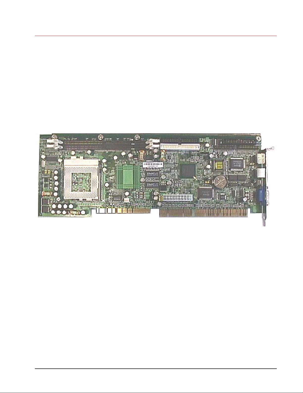
Board Features
Cache Memory
Voltage regulators
DIMMs
Processor(s)
Connectors
Jumper switches
Specific features are discussed in the following sections. Important features include:
Figure 1 – SBP-205
Cache Memory
The SBP-205 provides an internal 64-bit wide, non-blocking, second level (L2)
cache supporting 256KB running at full CPU speed. The cache modules are inside
the CPUs, and provide 32KB of first level (L1) cache.
Voltage Regulators
The nine voltage regulators mounted on the SBP-205 provide compatibility with a
full line of processors.
• CSS Laboratories Section 1 – SBP-205 Features • 2
Page 7

•
Microprocessor
The SBP-205 supports a single Pentium III® processor operating at speeds up to
1GHz. The processor features include:
Dynamic Execution performance with Multiple Branch Prediction,
Data Flow Analysis and Speculative Execution.
Multi-transaction system bus.
Dual Independent Bus Architecture, which allows data access from
either bus simultaneously or in parallel.
Intel™ MMX multimedia technology.
32KB (16KB/16KB) non-blocking, L1 cache.
66/100/133 MHz bus speed.
Error correction, fault analysis, recovery and functional redundancy
checking for both system and L2 cache busses.
• CSS Laboratories Section 1 – SBP-205 Features • 3
Page 8

•
Section 2 – Using the SBP-205
Connectors
Connector designations are stamped in white on the SBP-205 board.
SBP-205 Board Connector Descriptions
Connector Description
IDE1 Primary IDE connector
IDE2 Secondary IDE connector
USB1 USB0 (Universal Serial Bus 1)
USB2 USB1 (Universal Serial Bus 2)
FDD Diskette drive connector
LPT1 Parallel port
Mouse PS/2 mouse connector
Keyboard PS/2 keyboard connector
Chassis Fan Spare fan connector
VGA Video connector
COM1 Serial port 1 connector (COM 1)
COM2 Serial port 2 connector (COM 2)
Battery Battery
Power ATX power supply unit connector
CPU Fan Processor fan connectors
• CSS Laboratories Section 2 – Using the SBP-205 • 4
Page 9
•
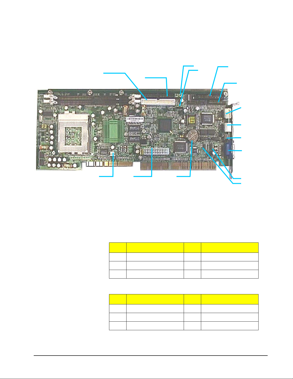
The following illustration,
Figure 2 – SBP-205 Connectors, shows the on-board location of the connectors
detailed in the above descriptions chart.
IDE1
USB2
USB1
IDE2
FDD
LPT1
Mouse
Keyboard
Chassis
Fan
VGA
Power CPU Fan Battery
COM2
COM1
Figure 2 – SBP-205 Connectors
Keyboard and Mouse
The 6-pin PS/2 keyboard and mouse connectors are keyed for proper installation.
PS/2 Keyboard Connector Pin Assignments
Pin Assignment Pin Assignment
1 Keyboard Data 4 +5 Vdc
2 Not Used 5 Clock
3 Ground 6 Not Used
PS/2 Mouse Connector Pin Assignments
Pin Assignment Pin Assignment
1 Mouse Data 4 +5 Vdc
2 Not Used 5 Clock
3 Ground 6 Not Used
• CSS Laboratories Section 2 – Using the SBP-205 • 5
Page 10

•
IDE, Primary and Secondary
The primary PCI IDE connector is designated IDE1. The secondary PCI IDE
connector is designated IDE2. Both are 40-pin connectors.
IDE Connectors (IDE1, IDE2) Pin Assignments
Pin Assignment Pin Assignment
1 Reset IDE 2 Ground
3 Host Data 7 4 Host Data 8
5 Host Data 6 6 Host Data 9
7 Host Data 5 8 Host Data 10
9 Host Data 4 10 Host Data 11
11 Host Data 3 12 Host Data 12
13 Host Data 2 14 Host Data 13
15 Host Data 1 16 Host Data 14
17 Host Data 0 18 Host Data 15
19 Ground 20 Key
21 DDRQ (DDRQ1) 22 Ground
23 I/O Write # 24 Ground
25 I/O Read # 26 Ground
27 IOCHRD 28 470 Ω (ohm) pull down
29 DDACK0 (DDACK1) # 30 Ground
31 IRQ14 (IRQ15) 32 Reserved
33 Addr1 34 Reserved
35 Addr0 36 Addr2
37 Chip Select 1P (1S) # 38 Chip select (3P 3S)
39 Activity # 40 Ground
• CSS Laboratories Section 2 – Using the SBP-205 • 6
Page 11

•
Parallel Port
The parallel port connector is a 26-pin connector.
Parallel Port Connector Pin Assignments
Pin Assignment Pin Assignment
1 STE 14 Ground
2 AFD # 15 PD6
3 PD0 16 Ground
4 ERR # 17 PD7
5 PD1 18 Ground
6 INIT # 19 ACK #
7 PD2 20 Ground
8 SLIN # 21 BUSY
9 PD3 22 Ground
10 Ground 23 PE
11 PD4 24 Ground
12 Ground 25 SLCT
13 PD5 26 Not Used
Serial Ports (COM1, COM2)
The SBP-205 features two 9-pin serial ports and connectors. They are designated
COM1 (serial port 1) and COM2 (serial port 2).
Serial Port Connectors (COM1, COM2) Pin Assignments
Pin Assignment Pin Assignment
1 DCD 6 DSR
2 RXD 7 RTS
3 TXD 8 CTS
4 DTR 9 RI
5 Ground
• CSS Laboratories Section 2 – Using the SBP-205 • 7
Page 12

•
Diskette Drive (FDD)
The diskette drive, also called the floppy drive, is a 34-pin connector, designated
FDD.
Diskette Drive Connector (FDD) Pin Assignments
Pin Assignment Pin Assignment
1 Ground 2 DENSEL
3 Ground 4 TP
5 Key 6 FDENIN #
7 Ground 8 FDINDX #
9 Ground 10 FDM00 #
11 Ground 12 FDDS01 #
13 Ground 14 FDDS004#
15 Ground 16 FDM01#
17 MSEN1 18 FDDIR #
19 Ground 20 FDSTEP #
21 Ground 22 FDWD #
23 Ground 24 FDWE #
25 Ground 26 FDTRK0 #
27 MSEN0 28 FDWPD #
29 Ground 30 FDRDATA #
31 Ground 32 FDRHEAD #
33 Ground 34 DSKCHG #
Universal Serial Bus (USB)
The SBP-205 provides connectors for two Universal Serial Bus (USB) connectors.
They are designated USB1) and USB2).
USB Connector (USB1, USB2) Pin Assignments
Pin Assignment Pin Assignment
1 VCC 3 Data +
2 Data – 4 Ground
• CSS Laboratories Section 2 – Using the SBP-205 • 8
Page 13
•
Memory
Processor Cooling Fan (CPU Fan)
The SBP-205 provides a 3-pin processor cooling fan connector. It is designated CPU
Fan.
Processor Cooling Fan Connector (CPU Fan) Pin Assignments
Pin Assignment Pin Assignment
1 Ground 2 12 volt
3 Sense
The SBP-205 provides two 168-pin DIMM sockets. The board supports up to
512MB of RAM with each socket supporting DIMMs up to 256 MB.
Memory Guidelines
The SBP-205 comes with 128 MB SDRAM installed in one DIMM socket. When
selecting additional memory, use the following guidelines.
The SBP-205 supports either FSB ECC or non-ECC SDRAM PC-133.
SDRAM PC-133 can be installed in one or both DIMM sockets.
Minimum memory size is 64MB; maximum total memory size is
512MB. Memory size and speed can vary between sockets.
Select 168-pin DIMM sizes as detailed in the following chart:
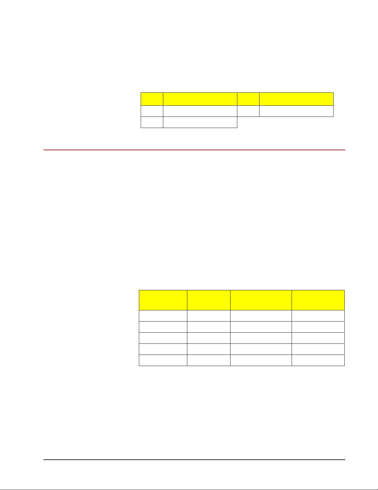
SBP-205 Supported DIMM Sizes
DIMM
Capacity
64 MB 64 Mbit 4M X 16 8
64 MB 64 Mbit 8M X 8 8
128 MB 64 Mbit 8M X 8 16
256 MB 64 Mbit 8M X 8 32
512 MB 128Mbit 32Mx4 32
SDRAM
Density
SDRAM
Organization
Number of
SDRAMs
SPD Data Structure
To be fully compliant with all applicable Intel® SDRAM memory specifications,
populate the SBP-205 with DIMMs that support the Serial Presence Detect (SPD)
data structure.
If the installed memory modules do not support SPD, you will see a notification to
this effect on the screen at power up. The BIOS will attempt to configure the
memory controller for normal operation.
• CSS Laboratories Section 2 – Using the SBP-205 • 9
Page 14
•
Recommended Memory Configuration
The following table displays the recommended system memory configuration,
starting at 64 MB.
SBP-205 System Memory Configuration
RAM Bank 0 Bank 1 RAM Bank 0 Bank 1
64 MB 8M x 64/72 256 MB 32M x 64/72
128 MB 8M x 64/72 8M x 64/72 320 MB 32M x 64/72 8M x 64/72
128 MB 16M x 64/72 384 MB 16M x 64/72 32M x 64/72
192 MB 16M x 64/72 8M x 64/72 512 MB 32M x 64/72 32M x 64/72
256 MB 16M x 64/72 16M x 64/72
Installing and Removing Memory
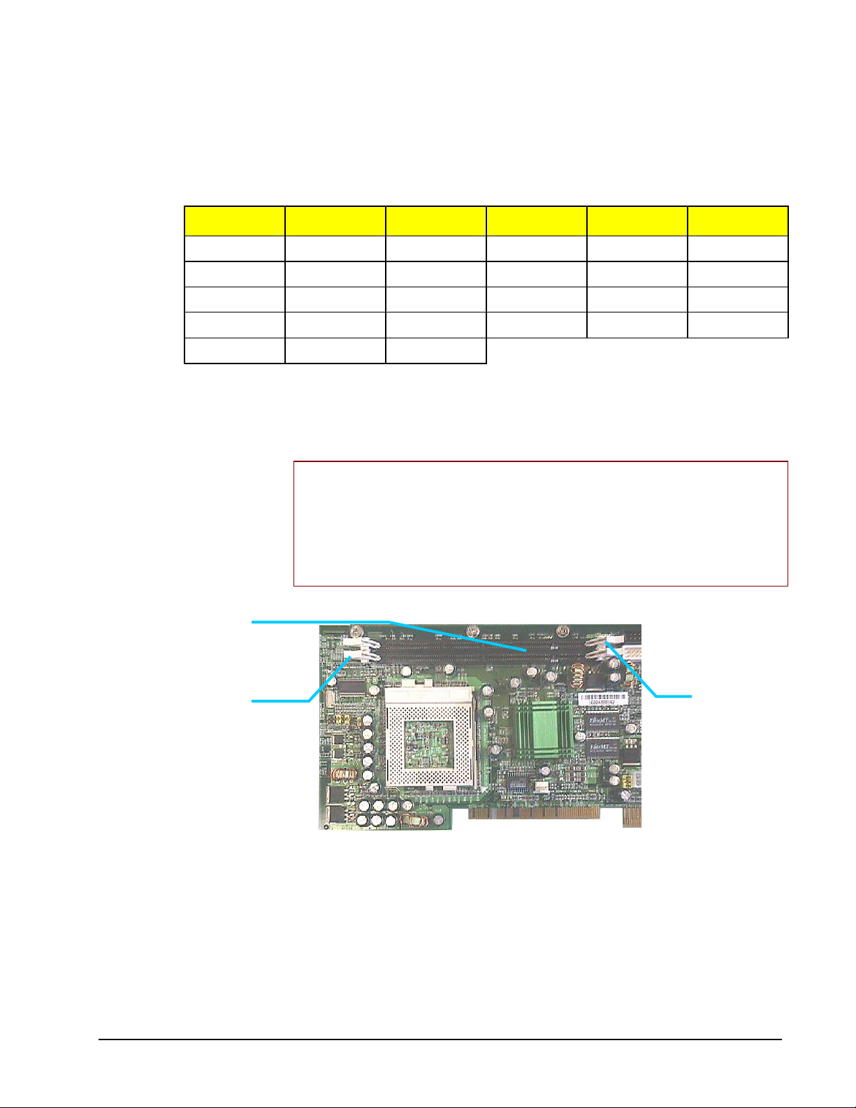
The SBP-205 DIMM sockets are located on the left side of the board.
DIMM Sockets
Locking Clips
IMPORTANT NOTE: It should not be necessary to remove the single board
computer from the passive backplane or the system chassis in order to remove or
install memory modules. However, it is very important to properly support the board
while applying pressure during DIMM removal or installation. On-board circuits,
connectors or the board itself could be damaged if not properly supported.
Ground or discharge any static electricity before making hardware modifications.
Locking Clips
Figure 3 – SBP-205 DIMM Sockets
Follow these steps to install or remove memory modules:
1. Power down the system and remove the power cord.
2. Open the system case following the steps in the User Guide provided
with your MaxPro or ProRack system.
3. Locate the DIMM sockets on the SBP-205.
• CSS Laboratories Section 2 – Using the SBP-205 • 10
Page 15

•
Processor
4. Remove a DIMM by pressing the white locking clips down (away from
the memory module). Lift the DIMM straight out of the socket.
5. Position the new DIMM it so that it aligns with the socket. (The DIMM
and the socket are keyed for correct orientation). Gently press straight
down until the module clicks into place.
6. Press the two white locking clips up into locked position.
7. Close the system case and power up the system.
As the system boots, the BIOS will automatically detect the new memory
configuration.
The SBP-205 supports a single Pentium III processor operating at up to 1 GHz. The
processor mounting includes a single edge contact (SEC) slot and an attached
mounting and retention bracket. The SBP-205 accepts a Pentium II/III processor
packaged in an SECC-2 cartridge.
The system operation with single or dual processors is automatically configured by
the operating system or network operating system. With dual processors installed,
the two CPUs function symmetrically.
Processor Overview
The SBP-205 processor mounts in the 370 socket. An on-board heat sink is mounted
on the board to the right of the 370 socket.
Installing and Removing a Processor
Follow these steps to remove and install a processor:
To prepare for installation and removal:
1. Power down the system and remove the power cord and any other
external connectors.
2. Open the system case following the steps in the User Guide provided
with your MaxPro or ProRack system.
3. Make sure to ground yourself by touching the system case before
touching any components.
IMPORTANT NOTE: It should not be necessary to remove the single board
computer from the passive backplane or the system chassis in order to remove or
install a processor. However, it is very important to properly support the board while
applying pressure during processor removal or installation. On-board circuits,
connectors or the board itself could be damaged if not properly supported.
To remove a processor:
1. Disconnect the cooling fan power connector from the on-board power
connector.
• CSS Laboratories Section 2 – Using the SBP-205 • 11
Page 16

•
2. Remove the fan/heat sink from on top of the processor by undoing the
mounting clip.
3. Lift and release ZIF-socket arm.
4. Lift the processor out of the 370 socket.
To install a processor:
1. Lift and release ZIF-socket arm.
2. Position the processor with pins lined up with socket.
3. Gently press processor into socket until into place.
4. Push down ZIF-socket arm and lock.
5. Attach fan/heat sink on top of the processor and secure with mounting
clip.
6. Plug the cooling fan power connector into the on-board power
connector (CPU Fan).
The system will boot and the BIOS will automatically detect the new processor.
SBP-205 Installation
The MaxPro tower server or ProRack rackmount system has been fully set up by
CSS Laboratories before delivery. The passive backplane and single board
computer(s) have been installed and configured at the factory.
Typically, no single board computer (SBC) installation is necessary. However, the
modular design of the MaxPro and ProRack systems enables you to customize them
to meet specific needs. Swapping out the single board computer(s) is one way the
MaxPro and ProRack systems can be customized and upgraded.
Overview
The SBP-205 connects to any CSS Laboratories passive backplane through one
EISA connector with a PCI bus extension. This SBC connector socket combination
is located on the passive backplane.
Installing the SBP-205 to a Passive Backplane
7. Close the system case and reconnect the external cables.
8. Power up the system.
It is not necessary to remove the passive backplane from the system chassis in order
to remove or install the SBP-205.
To prepare the system and SBC for installation:
1. Power down the system and remove the power cord and any other
external connectors.
2. Open the system case.
• CSS Laboratories Section 2 – Using the SBP-205 • 12
Page 17

•
Follow the instructions in the MaxPro or ProRack User Guide that
accompanied your system.
3. Inspect the SBP-205 jumper settings and reset them as needed.
The SBP-205 jumper switches are pre-set at the factory. If any changes
are needed, it is easier to make them before installing the SBC. See
Jumper Switches for information and procedures.
4. Install the processor and the DIMMs.
It is easier to install a processor and DIMMs to the SBC before the
SBC itself is installed. See Installing and Removing Memory and
Installing and Removing a Processor for procedures.
To remove an installed SBC:
1. Unplug any EIDE or other data cables and port connectors from the
SBC.
2. Remove the retaining screw located at the rear of the system case.
3. Lift the SBC from the sockets on the passive backplane.
All MaxPro and ProRack series chassis come with protective stabilizer
bracket is part of the chassis. This bracket must be removed in order to
remove the SBC. Refer to the MaxPro, ProRack User Guide for
removal procedures.
4. Remove the DIMMs from the installed SBC.
See Installing and Removing Memory for procedures.
5. Remove the processor from the installed SBC.
See Installing and Removing a Processor for procedures.
To install the SBP-205:
1. Position the SBP-205 over the sockets on the passive backplane.
Make sure that the connector pins are facing down. The SBP-205 will
install in only one direction. The correct SBC sockets are the EIDE
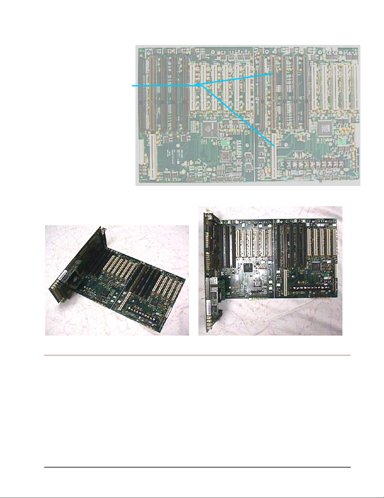
with the PCI bus extension. See Figure 4 – Passive Backplane and
Figure 5 – SBC Installed to Passive Backplane for sample illustration
using the PB11109 passive backplane.
2. Gently press the SBP-205 into the sockets until it clicks into place.
3. Replace the retaining screw at the rear of the system case.
4. Connect the EIDE cables, along with any other data cables and external
port connectors.
5. Close the system case.
6. Reconnect the power cord and the external connectors, and power up
the system.
As the system boots, the BIOS will detect the SBP-205 settings. You may need to
manually reconfigure the system. See BIOS Configuration for procedures to
configure the BIOS and CMOS.
• CSS Laboratories Section 2 – Using the SBP-205 • 13
Page 18
•
SBC Connector Slots
(EISA Connector and PCI
Bus Extension)
Figure 4 – Passive Backplane
Figure 5 – SBC Installed to Passive Backplane
Jumper Switches
The SBP-205 jumper switches are pre-configured at the factory. Jumpers are used to
configure the processor bus frequency and to clear CMOS contents.
Jumper Switches Overview
The Pentium III processor uses a clock multiplier to match the processor core
frequency with the speed of the processor bus—the speed at which data travels into
and out of the processor. Four jumper switches determine the processor bus
frequency. Another jumper temporarily clears the CMOS contents.
• CSS Laboratories Section 2 – Using the SBP-205 • 14
Page 19
•
NOTE: With the new Pentium III processor, it is not necessary to set jumper
switches to determine the bus processor frequency. The Pentium III processor is selfadjusting.
Two-pin jumpers are described as jumped, “on” or “in” with the small plastic jumper
cap on, or not jumped, “off” or “out” with the jumper cap off.
Jumpers with more than two pins are described by numbering the pins. Each of the
SBP-205 jumpers has the number “1” stamped on the board next to that jumper’s pin
number one.
The jumper cap placed over a particular combination of pins, such as 1-2 or 2-3,
determines the jumper setting.
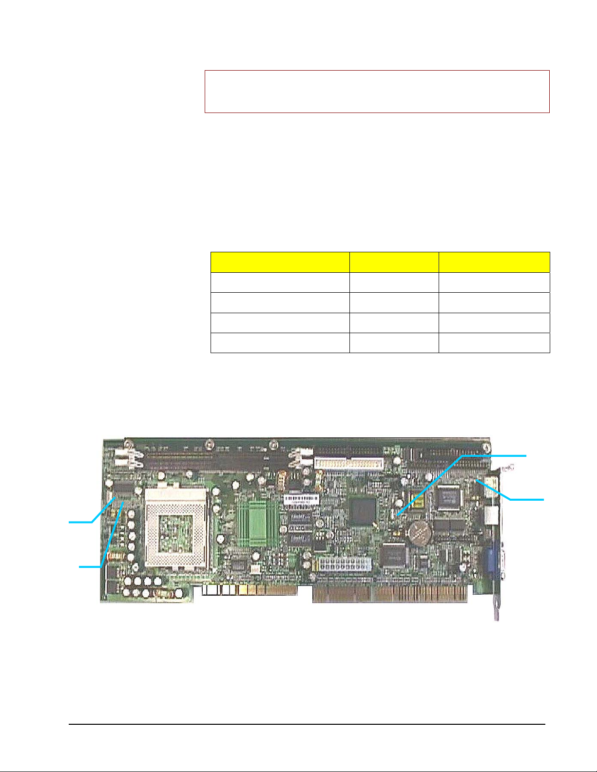
SBP-205 Jumpers
Jumper Designation Number of Pins Jumper Function
JP2 3 Clear CMOS contents
JP5 3 CPU Setting
JP7
JP6 3 Keyboard Power On
JP7 10 CPU Clock
See Figure 6 – SBP-205 Jumper Switches for the location of the jumpers.
JP2
JP6
JP5
Figure 6 – SBP-205 Jumper Switches
• CSS Laboratories Section 2 – Using the SBP-205 • 15
Page 20
•
Setting Jumper Switches
Setting jumper switches is easiest with the SBP-205 removed from the system. While
the jumper switches are accessible with the SBP-205 installed, it might be necessary
to remove one or more adapter cards if they restrict access to the jumpers.
To access the jumper switches:
1. Power down the system and remove the power cord and any other
external connectors.
2. Open the system case.
Follow the instructions in the MaxPro or ProRack User Guide that
accompanied your system.
3. Locate the jumper switches you wish to set.
4. Temporarily remove any adapters or connectors that restrict your
access to the jumper switches.
5. If necessary, temporarily remove the SBP-205 from the system.
For SBP-205 removal and installation procedures, see Installing the
SBP-205 to a Passive Backplane.
To temporarily clear the CMOS:
CMOS contains the system BIOS configurations. Temporarily placing a jumper cap
on JP17 pins 2-3 clears the contents of the CMOS chip.
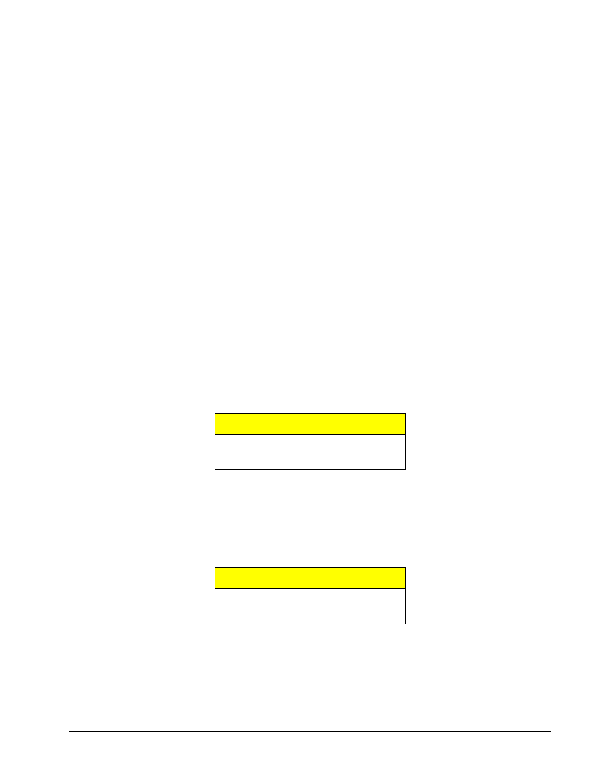
Clear CMOS Contents, JP2
Status Pins
Clear CMOS 1-2
Normal (default) 2-3
Remember to reset the jumper cap to the default position after clearing the CMOS
contents.
To set the CPU setting
CPU Setting, JP5
Status Pins
Intel 1-2
Cyrix 2-3
• CSS Laboratories Section 2 – Using the SBP-205 • 16
Page 21
•
To set keyboard power on:
Keyboard Power On, JP6
Status Pins
Enable 1-2
Disable 2-3
To set CPU clock speed::
The Pentium III processor automatically adjusts processor speed ratios. There is no
need to reset jumper switches to match the bus speed and the processor clock speed.
With a Pentium II processor, jumper settings are used to multiply the bus speed to
match the processor clock speed. The SBP-205 provides a chart stamped on the
board which gives the processor speed ratios at different settings of jumper JP7.
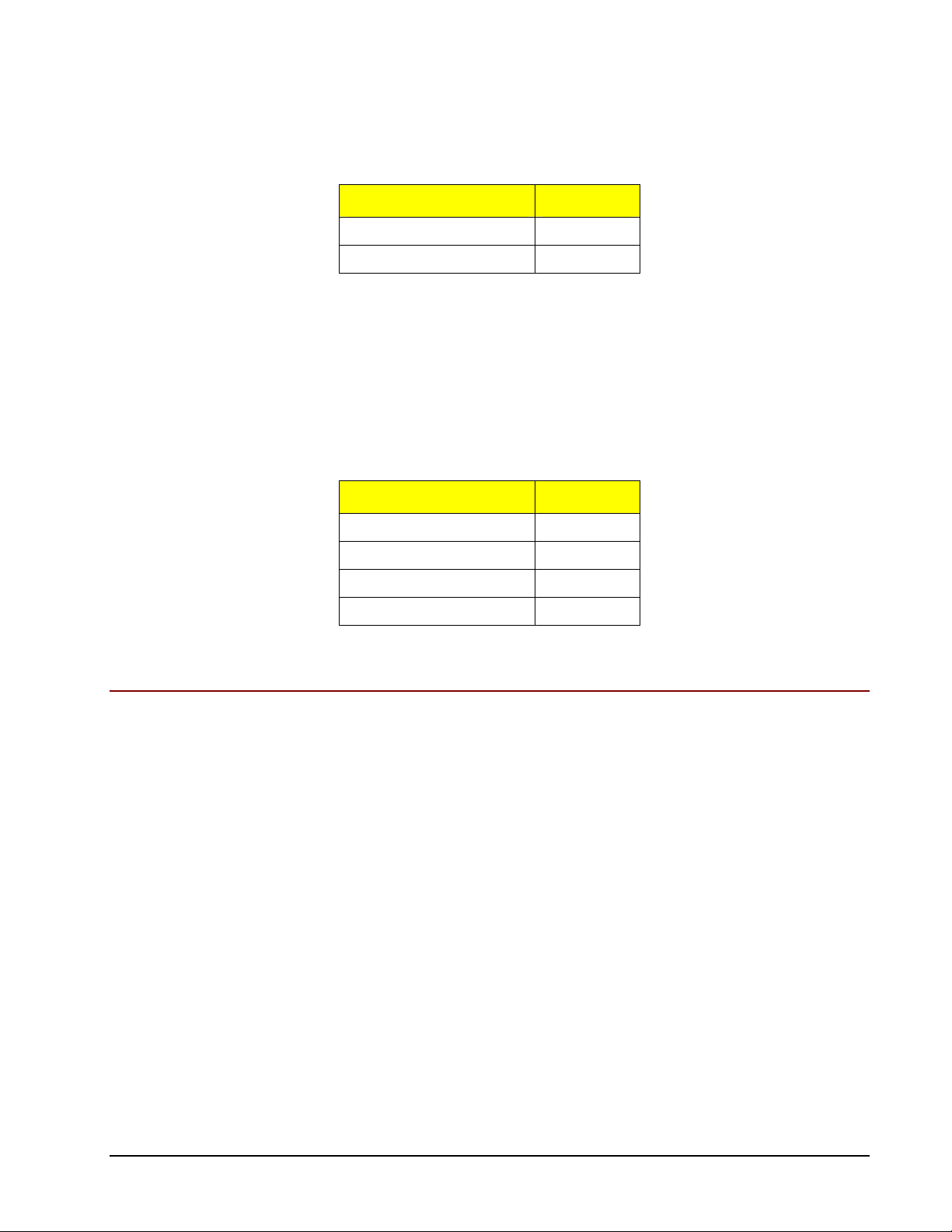
CPU Clock, JP7
Status Pins
Auto 1-2, 3-4
66 5-6
100 7-8
133 9-10
BIOS Configuration
BIOS Configuration Overview
The SBP-205 features an AMI BIOS with built-in CMOS setup for system
parameters, peripheral management and PCI bridge and interrupt steering.
The MaxPro tower servers and ProRack rackmount systems with the SBP-205
installed automatically detect and configure PCI-compliant adapters while booting.
The BIOS automatically sets the adapter IRQ levels and I/O addresses each time the
computer starts.
Resource configuration is complete when the operating system starts. If the system
displays an error while booting, it may require additional steps to configure.
Access the BIOS setup by pressing the [Delete] key after the POST memory test
begins and before the operating system boot begins.
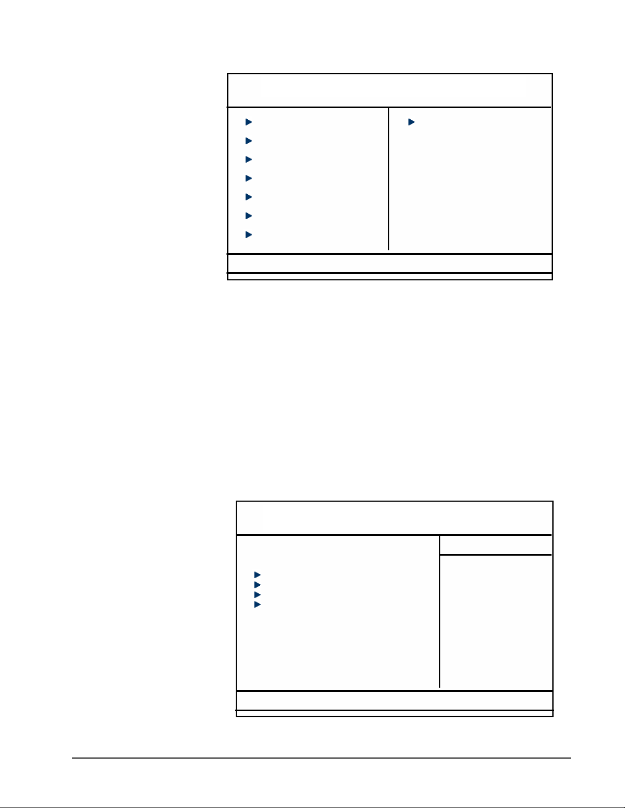
The following illustration shows the menus available from the BIOS setup utility
main menu.
In all menus, use the up and down arrow (
Use the <PgUp> and <PgDn> keys to toggle options for a given item.
• CSS Laboratories Section 2 – Using the SBP-205 • 17
↑↓) keys on the keyboard to select an item.
Page 22
•
CMOS Setup Utility – Copyright © 1984-2001 Award Software
Standard CMOS Features
Advanced BIOS Features
Advanced Chipset Features
Integrated Peripherals
Power Management Setup
PnP/PCI Configurations
PC Health Status
Esc : Quit
F10 : Save & Exit Setup
Frequency/Voltage Control
Load Fail-Safe Defaults
Load Optimized Defaults
Set Supervisor Password
Set User Password
Save & Exit Setup
Exit Without Saving
↑ ↓ → ← : Select Item
Figure 7 – BIOS Setup Main Menu
The most commonly accessed setup procedures are discussed in the following topics.
These are:
Standard CMOS Setup
Advanced CMOS Setup
Advanced Chipset Setup
Power Management Setup
PCI/Plug and Play Setup
Peripheral Setup
Setting Up CMOS—Standard Setup
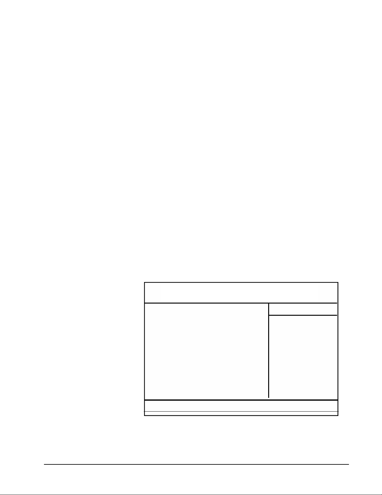
The Standard Setup utility records the system setup to CMOS. Select Standard
CMOS Setup from the main menu.
CMOS Setup Utility –Copyright © 1984-2001 Award Software
Date (mm:dd:yy) Mon, Dec 10 2001
Time (hh:mm:ss) 14 : 46 : 58
IDE Primary Master [ None ]
IDE Primary Slave [ None ]
IDE Secondary Master [ None ]
IDE Secondary Slave [ None ]
Drive A [ 1.44M, 3.5 in. ]
Drive B [ None ]
Video [ EGA/VGA ]
Halt On [ All , But Keyboard ]
↑ ↓ → ←: Move Enter: Select +/-/PU/PD: Value F10: Save Esc: Exit F1: General Help
F5: Previous Values F6: Fail-Safe Defaults F7: Optional Defaults
Standard CMOS Features
Figure 8 – Standard CMOS Setup
Item Help
• CSS Laboratories Section 2 – Using the SBP-205 • 18
Page 23
•
Pri Master
This option sets the primary master EIDE/PCI hard drive. It defines the drive modes
and parameters. The default setting is Auto to auto-detect the drive type and settings.
Pri Slave
This options sets the primary slave EIDE/PCI hard drive. It defines the parameters
and modes. The default setting is Auto to auto-detect the drive type and settings.
Sec Master
This option sets the secondary master EIDE/PCI hard drive if one is installed. It
defines the drive parameters and modes. The default setting is Not Installed.
Sec Slave
This option sets the secondary slave EIDE/PCI hard drive if one is installed. It
defines the drive parameters and modes. The default setting is Not Installed.
Floppy Drive A, Floppy Drive B
This option selects the type of drive that matches the installed diskette drive. Scroll
through the drive types by using the up and down arrow keys on the keyboard.
Date, Time
Enter the new values as necessary.
Setting Up CMOS—Advanced Setup
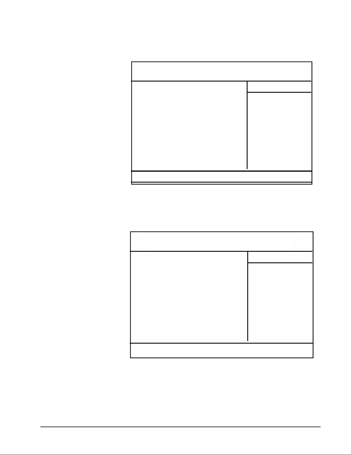
CMOS Setup Utility –Copyright © 1984-2001 Award Software
Virus Warning
CPU Internal Cache
External Cache
CPU L2 Cache ECC Checking
Processor Number Feature
Quick Power On Self Test
First Boot Device
Second Boot Device
Third Boot Device
Boot Other Device
Swap Floppy Drive
Boot Up Floppy Seek
Boot Up NumLock Status
Gate A20 Options
Typematic Rate Setting
Security Option
↑ ↓ → ←: Move Enter: Select +/-/PU/PD: Value F10: Save Esc: Exit F1: General Help
F5: Previous Values F6: Fail-Safe Defaults F7: Optional Defaults
Figure 9 – Advanced CMOS Setup, First Page
Advanced BIOS Features
[ Disabled ]
[ Enabled ]
[ Enabled ]
[ Enabled ]
[ Enabled ]
[ Enabled ]
[ Floppy ]
[ HDD-O ]
[ LS120 ]
[ Enabled ]
[ Disabled ]
[ Enabled ]
[ On ]
[ Fast ]
[ Disabled ]
[ Setup ]
Item Help
Advanced Setup displays two screens of options to fine tune a number of system
features. Select Advanced CMOS Setup from the main menu.
• CSS Laboratories Section 2 – Using the SBP-205 • 19
Page 24
•
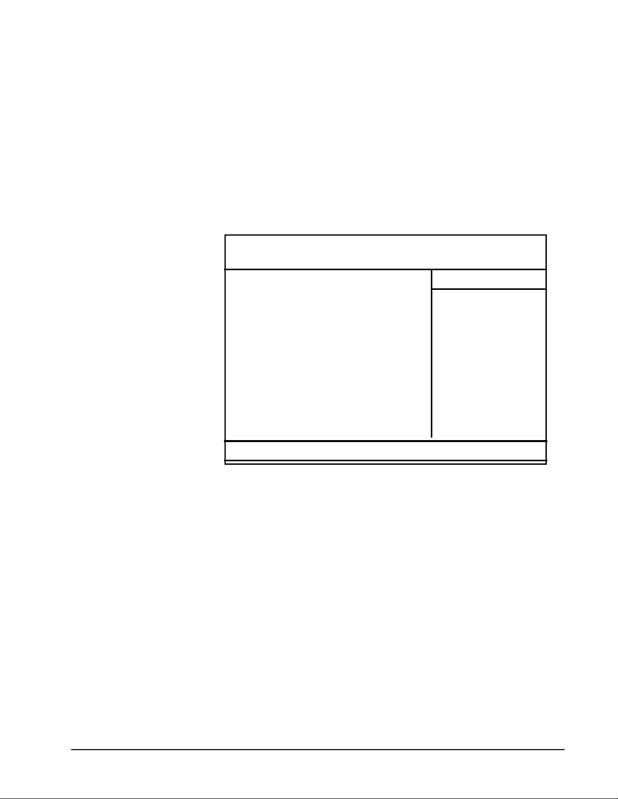
Use the up and down arrow keys to select an item. Options for each item are
displayed in the right-hand column. Press <PgUp> or <PgDn> to toggle the options.
CMOS Setup Utility –Copyright © 1984-2001 Award Software
CPU L2 Cache ECC Checking
Processor Number Feature
Quick Power On Self Test
First Boot Device
Second Boot Device
Third Boot Device
Boot Other Device
Swap Floppy Drive
Boot Up Floppy Seek
Boot Up NumLock Status
Gate A20 Options
Typematic Rate Selling
Security Option
OS Select For DRAM > 64MB
Report No FDD for WIN 95
Small Logo(EPA) Show
↑ ↓ → ←: Move Enter: Select +/-/PU/PD: Value F10: Save Esc: Exit F1: General Help
F5: Previous Values F6: Fail-Safe Defaults F7: Optional Defaults
Advanced BIOS Features
[ Enabled ]
[ Enabled ]
[ Enabled ]
[ Floppy ]
[ HDD-O ]
[ LS120 ]
[ Enabled ]
[ Disabled ]
[ Enabled ]
[ On ]
[ Fast ]
[ Disabled ]
[ Setup ]
[ Non-OS2 ]
[ No ]
[ Disabled ]
Item Help
Figure 10 – Advanced CMOS Setup, Second Page
Setting Up CMOS—Advanced Chipset Setup
The chipset has been pre-configured, but Advanced Chipset Setup gives you two
pages of options to configure some of the advanced system features.
CMOS Setup Utility –Copyright © 1984-2001 Award Software
SDRAM CAS Latency Time
SDRAM Cycle Time Tras/Trc
SDRAM RAS-to-CAS Delay
SDRAM RAS Freecharge Time
System BIOS Cacheable
Video BIOS Cacheable
Memory Hole at 15M-16M
CPU Latency Time
Delayed Transaction
On-Chip Video Window Size
Local Memory Frequency
CAS# Latency
Paging Mode Control
RAS-toCAS Override
RAS# Timing
RAS# Freecharge Timing
↑ ↓ → ←: Move Enter: Select +/-/PU/PD: Value F10: Save Esc: Exit F1: General Help
F5: Previous Values F6: Fail-Safe Defaults F7: Optional Defaults
Advanced Chipset Features
[ 3 ]
[ Auto ]
[ Auto ]
[ Auto ]
[ Disabled ]
[ Disabled ]
[ Disabled ]
[ Disabled ]
[ Enabled ]
[ 64MB ]
[ 100 Mhz ]
[ 3 ]
[ Open ]
[ by CAS# LT ]
[ Fast ]
[ Fast ]
Item Help
Figure 11 – CMOS Advanced Chipset Setup
Configuring Power Management
The power management options include:
• CSS Laboratories Section 2 – Using the SBP-205 • 20
Page 25
•
Enable/Disable system power management
An inactivity timer to set the amount of time before the system enters
standby mode.
Hard disk power management during standby and suspend modes.
Video power management during standby and suspend modes.
Fan power management.
Configuring PCI/Plug and Play
Use the PCI/Plug and Play Setup to define attributes of the PCI bus portion of the
SBP-205.
CMOS Setup Utility –Copyright © 1984-2001 Award Software
PNP OS Installed
Reset Configuration Data
Resources Controlled By
PCI/VGA Palette Snoop
↑ ↓ → ←: Move Enter: Select +/-/PU/PD: Value F10: Save Esc: Exit F1: General Help
F5: Previous Values F6: Fail-Safe Defaults F7: Optional Defaults
PnP/PCI Configurations
[ No ]
[ Disabled ]
[ Auto(ESCD)]
[ Disabled ]
Item Help
Figure 12 – CMOS PCI/PNP Setup
• CSS Laboratories Section 2 – Using the SBP-205 • 21
Page 26
•
Setting Up Peripherals
Use Peripherals Setup to specify the peripheral devices installed.
The On-Board IDE option enables the on-board chipset EIDE function.
CMOS Setup Utility –Copyright © 1984-2001 Award Software
On-Chip Primary PCI IDE
On-Chip Secondary PCI IDE
IDE Primary Master PIO
IDE Primary Slave PIO
IDE Secondary Master PIO
IDE Secondary Slave PIO
IDE Primary Master UDMA
IDE Primary Slave UDMA
IDE Secondary Master UDMA
IDE Secondary Slave UDMA
USB Controller
USB Keyboard Support
Init Display First
IDE HDD Block Mode
Power On Function
Onboard FDC Controller
Onboard Serial Port 1
↑ ↓ → ←: Move Enter: Select +/-/PU/PD: Value F10: Save Esc: Exit F1: General Help
F5: Previous Values F6: Fail-Safe Defaults F7: Optional Defaults
Integrated Peripherals
[ Enabled ]
[ Enabled ]
[ Auto ]
[ Auto ]
[ Auto ]
[ Auto ]
[ Auto ]
[ Auto ]
[ Auto ]
[ Auto ]
[ Enabled ]
[ Disabled ]
[ PCI Slot ]
[ Enabled ]
[ BUTTON ONLY ]
[ Enabled ]
[ 3F8/IRQ4 ]
Item Help
Figure 13 – Peripherals Setup
CMOS Setup Utility –Copyright © 1984-2001 Award Software
USB Keyboard Support
Init Display First
IDE HDD Block Mode
Power On Function
Onboard FDC Controller
Onboard Serial Port 1
Onboard Serial Port 2
UART Mode Select
Onboard Parallel Port
Parallel Port Mode
PWRON After PWR-Fail
Integrated Peripherals
[ Disabled ]
[ PCI Slot ]
[ Enabled ]
[ BUTTON ONLY ]
[ Enabled ]
[ 3F8/IRQ4 ]
[ 2F8/IRQ3 ]
[ Normal ]
[ 378/IRQ7 ]
[ SPP ]
[ Off ]
Item Help
↑ ↓ → ←: Move Enter: Select +/-/PU/PD: Value F10: Save Esc: Exit F1: General Help
F5: Previous Values F6: Fail-Safe Defaults F7: Optional Defaults
• CSS Laboratories Section 2 – Using the SBP-205 • 22
Page 27

•
Section 3 – Maintenance and
Troubleshooting
Routine Maintenance
Follow these basic steps to maintain and safeguard the SBP-205 single board
computer:
The MaxPro tower server chassis and the ProRack rackmount chassis are
designed to provide protection for internal devices and connections. Care must
still be taken to ensure that the system case won’t be kicked or struck. An impact
could damage disk drives.
Do not place the MaxPro or the ProRack near any heat source that may damage
it, such as heaters, direct sunlight, etc.
Do not eat, drink or smoke near the system.
Troubleshooting
Use a surge protector with the MaxPro or ProRack and any peripheral devices.
Power surges can damage or destroy the SBP-205 or other components. Surges
can also destroy data on the hard drives.
Allow a space of at least eight inches around your system for proper ventilation.
Do not plug the MaxPro or ProRack into the same electrical circuit with a
“noisy” electric motor, such as a blender or a vacuum cleaner.
Ground yourself by touching the system case before touching any hardware or
software. This discharges the static electricity in your body. (Static electricity
can damage components).
Keep the system clean and free of dust. Use commercially available dust covers.
Troubleshooting Tools
The first and most important sign of trouble is that a particular device simply is not
working. The other main indicator is that you receive error messages, either on
power up or when attempting to use a particular device.
The SBP-205 functions only in conjunction with other components, including a
passive backplane and optional adapter cards. Most problems with the SBP-205 will
be traceable to connections or to software including the BIOS.
Several common physical problems and problems with related devices are discussed
in this section and in the Troubleshooting Using System Utilities topic later in this
section.
There are three main troubleshooting tools:
1. Direct inspection
2. Troubleshooting using system utilities
• CSS Laboratories Section 3 – Maintenance and Troubleshooting • 23
Page 28
•
The various Windows operating systems, for example, provide system
information, data on problem devices and other troubleshooting
utilities.
3. Troubleshooting Tables
These tables deal with problems and solutions that are primarily
physical in nature, but can also involve reconfiguring software
installations. The Troubleshooting Tables build upon and work with
what you learn by doing the initial inspection steps. Use all three tools
together as necessary.
Troubleshooting by Direct Inspection
First, make sure that the power cord(s) and all external connectors are properly
connected. Then make sure that the system itself and its peripherals are turned on,
particularly any peripheral that isn’t working.
Next, answer this question: Have you installed any new hardware or software since
the system was last working properly? If you have just added any new hardware or
software, then remove the software or device and see if the system now runs
correctly. If it does, reinstall the new device and/or software. Reinstalling often
resolves hardware conflicts and solves the problem.
Troubleshooting Using System Utilities
Different operating systems provide different arrays of troubleshooting and system
utilities. The steps outlined here provide an example of using the Windows NT
system utilities to pinpoint problem devices.
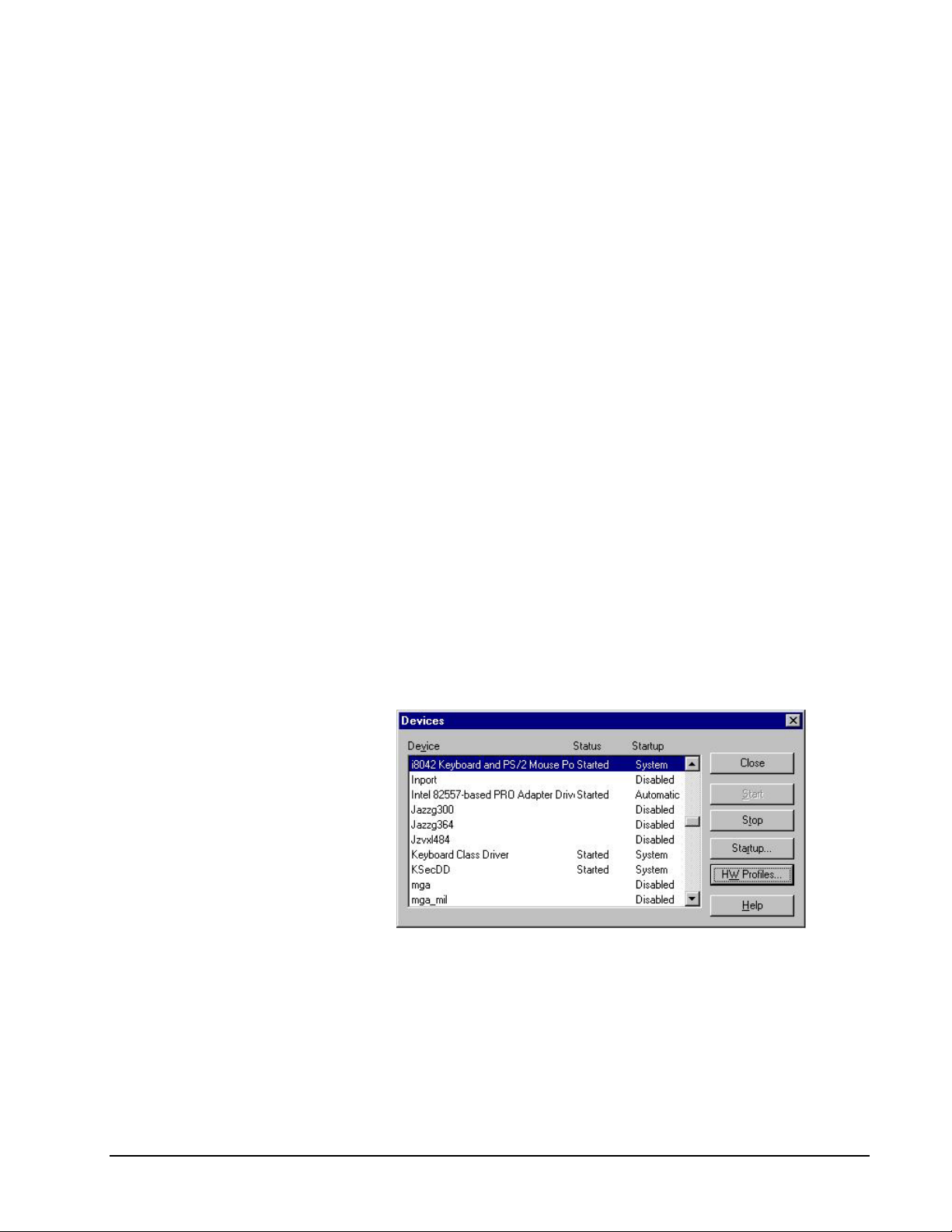
1. Access the Control Panel from the Start Menu or from the Windows
desktop.
2. Double-click the Devices icon. This will display the Devices window.
Figure 14—Windows NT Devices Window
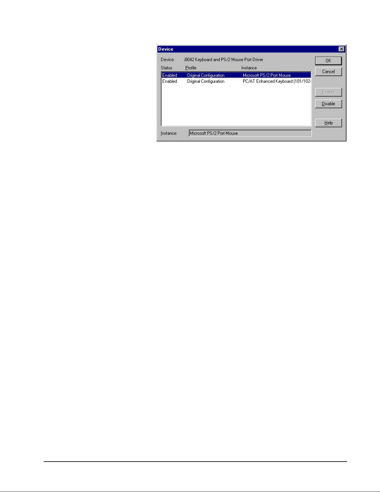
3. Select the problem device and click the HW Profiles button. This will
display the Device window.
4. Click the Enable button if the device is incorrectly disabled.
• CSS Laboratories Section 3 – Maintenance and Troubleshooting • 24
Page 29
•
Figure 15—Windows NT Device Window
5. Click the Disable button if the device is enabled and is still not
functioning properly.
6. Adjust the resource settings as necessary using the BIOS setup utility.
The resource settings include the IRQ and the I/O address currently in use by the
device. This often is where a device problem can occur, as the IRQ or the I/O
address settings can be the same as those for another device on the system.
If there is a device conflict, reinstalling the software drivers will usually reassign
IRQs and I/O addresses and often will resolve the conflict and the problem.
Windows NT does not provide direct control of device resource allocations or
hardware conflict information. Individual devices must be installed using the BIOS
utilities. See BIOS Configuration for more information.
Windows 2000 addresses this deficiency, and provides more detailed system
information and greater device installation control from within the operating system.
Troubleshooting Tables
The following tables list common problems and the basic handlings to resolve those
problems. The handlings are only the most likely steps to take, suggested guidelines.
Use them in conjunction with the direct inspection and system utilities tools
discussed earlier.
• CSS Laboratories Section 3 – Maintenance and Troubleshooting • 25
Page 30

•
SBP-205 Troubleshooting Tables
GENERAL PROBLEMS HANDLING
The system will not power on. 1. Make sure that the power cables are properly
connected.
2. Make sure that all power strips, UPS and power
outlets have power.
3. If you’ve just installed a new optional device, remove
it and reboot the system.
4. Make sure that all power switches on the MaxPro or
ProRack hot swappable power supplies are in the On
position.
If the problem persists, have the system serviced.
Damaged switches, broken indicator lights, etc. Have the system serviced and the broken or damaged parts
replaced.
Other power problems or intermittent power errors. 1. Make sure that all external power connectors are
properly seated and that the system power switches
are on, including the front panel switch, auxiliary
switches and individual power supply switches.
2. Make sure that the current selector switches on the
power supplies are set to the proper current (110v or
220v).
3. If this does not resolve the problem, inspect the P1
and P2 power connector on the passive backplane.
Also inspect the other power connectors such as the
Auxiliary P1 and P2 connectors and terminal lugs if
they are in use. Make sure that all connectors are
properly seated at both ends and that there are no
breaks in the wires.
If the problem persists, inspect the on-board connectors for
damaged pins. If any pins are damaged, have the system
serviced.
CMOS (system) clock errors. 1. Inspect the lithium 3.3 volt (BAT) connector on the
passive backplane. Make sure that the connector is
properly seated at both ends.
2. If the problem persists, inspect the battery located on
the SBP-205. Make sure that it is properly seated or
replace the battery.
3. If the problem persists, inspect the BAT connector on
the passive backplane for damaged pins. If any pins
are damaged, have the system serviced.
Reset button does not reset the system. 1. Inspect the reset/turbo (RST) connector on the passive
backplane. Make sure that the connector is properly
seated at both ends.
2. If the problem persists, inspect the RST connector on
the passive backplane for any damaged pins. If any
pins are damaged, have the system serviced.
If the problem persists, have the system serviced.
• CSS Laboratories Section 3 – Maintenance and Troubleshooting • 26
Page 31

•
INPUT DEVICE PROBLEMS HANDLING
Some or all of the keyboard keys don’t work. 1. Make sure that the keyboard is properly connected to
the system, and make sure that the system and the
monitor are turned on.
2. Test if the problem is with the keyboard or something
else by swapping out the keyboard with one from
another system.
3. If the problem lies with the keyboard itself, have it
serviced or replaced.
The mouse doesn’t work. 1. Make sure that the mouse is correctly connected to the
system. If so, use the Inspection steps outlined above
to determine if the mouse drivers are properly
installed and not in conflict with any other drivers.
2. If the problem persists, replace the mouse.
MONITOR PROBLEMS HANDLING
The screen is blank. 1. Make sure that the screen has not been blanked by
power management settings. If so, moving the mouse
or touching a key will bring the monitor back to active
mode.
2. Make sure that the monitor power cord is plugged into
a working electrical outlet.
3. Make sure that the monitor itself is turned on and that
the contrast and brightness are properly adjusted.
4. Make sure that the monitor cable is properly
connected to the system unit.
5. If these steps don’t resolve the problem, have the
monitor serviced or replaced.
The monitor screen is out of synchronization 1. Reduce the resolution of the video display adapter.
Consult the operating system and/or video display
adapter user guides for procedures.
2. Reduce the refresh rate. Consult the operating system
and/or video display adapter user guides for
procedures.
The screen flickers some or all of the time. Use the monitor software utilities (see your monitor user
manual) to set it for the highest possible refresh rate.
If the problem persists, have the monitor serviced or
replaced.
Distortion or some other kind of screen jitter, wavy image
or rolling image.
• CSS Laboratories Section 3 – Maintenance and Troubleshooting • 27
Check all monitor connections and any self-tests described
in your monitor’s user manuals. If the monitor checks out
OK, inspect the monitor’s location. Is it near some other
electromagnetic device such as an appliance, electrical
transformer, fluorescent lights, etc?
If so, turn off the monitor and either move it or the other
device a minimum of a foot apart. Turn the monitor back
on. If the problem still persists, have the monitor serviced
or replaced.
Page 32

•
MEMORY PROBLEMS HANDLING
The amount of memory displayed by the operating system
is less than the memory installed.
1. Make sure that the DIMMs are properly installed and
seated in their slots. You’ll have to open the system
case to do this. See Installing and Removing Memory
for information and procedures.
2. Make sure that the installed memory is the correct
type for the system, or if you have more than one
memory module installed, that all modules are
compatible. See Memory Guidelines for more
information.
If this is all correct, the operating system provides an array
of troubleshooters and diagnostics to help you identify the
problem. In Windows operating systems, this utility can be
accessed through Windows Help.
PORT OR PERIPHERAL DEVICE PROBLEMS HANDLING
The parallel port doesn’t work or isn’t recognized by the
system.
1. The parallel port is mounted on the SBP-205. Check
the BIOS setting to see if it has been disabled.
2. Open the system case and make sure that the parallel
port data cable and power connector are properly
seated in their slots on the SBP-205. Refer to
Connectors to make sure it’s in the right slot.
3. Use the system utilities troubleshooting steps to make
sure that the port has a unique I/O address and that it
is not in conflict with any other devices.
If the problem persists, have the system serviced.
The number of serial and parallel ports displayed is less
than the number installed.
A serial or parallel device doesn’t work. This includes
printers and any other devices that connect to serial or
parallel ports.
1. Make sure that the port has not been disabled in the
BIOS CMOS.
2. Use the system utilities to make sure that each port has
a unique I/O address and that none are in conflict with
any other devices.
3. Make sure that the internal port connectors are
properly seated in the proper slot on the SBP-205.
Refer to Connectors to make sure each is connected to
the correct slot.
If the problem persists, have the system serviced.
Make sure that the ports are functioning, as in the above
section of this table. Make sure that the device is properly
connected to the port, is turned on, and that the driver(s)
are properly installed.
If the problem persists, and the ports are functioning
properly, have the device serviced or replaced.
• CSS Laboratories Section 3 – Maintenance and Troubleshooting • 28
Page 33

•
PORT OR PERIPHERAL DEVICE PROBLEMS HANDLING
The system does not recognize an installed PCI or ISA
adapter.
1. Make sure that any external connections to the adapter
are properly connected.
2. Ensure that any software applications or drivers for
the PCI or ISA adapter have been installed correctly.
Consult the manual that came with the adapter for
specific troubleshooting steps.
3. If the problem persists, inspect the PCI or ISA
adapter. Make sure that it is properly seated into the
PCI or ISA slot. If any additional connectors are
required, make sure that they are properly seated.
4. If the problem persists, try installing the adapter to a
different slot.
If the problem persists and there are no other system
problems, have the adapter serviced or replaced.
DISKETTE DRIVE PROBLEMS HANDLING
The diskette drive isn’t working: the in-use light stays on,
or the system doesn’t recognize the drive at all.
Ensure that there is a diskette properly inserted in the
drive. If so, then make sure that the diskette itself is
properly formatted and isn’t damaged. Damage doesn’t
have to be evident to the naked eye—such as a cracked
casing. The diskette or the data on it could have been
damaged through becoming magnetized.
Make sure the floppy cable is connected correctly. The
floppy light will stay on if the cable is reversed.
If the diskette is okay, make sure it contains the proper
files to do what you want it to do (in the case of a software
installation or program diskette).
If the problem persists, have the system serviced. The
drive itself might be improperly connected or
malfunctioning.
• CSS Laboratories Section 3 – Maintenance and Troubleshooting • 29
Page 34

•
HARD DRIVE PROBLEMS HANDLING
A frontloading swappable hard drive doesn’t work or data
on the drive isn’t detected by the system or a flashing
green LED indicates a problem.
1. Gently press on the front of the drive tray to make
sure that the tray connectors are properly seated and
that the tray face is flush with the MaxPro or ProRack
system case.
2. If the drive still does not work, unlock the keylock and
remove the drive tray. Make sure that the power
connector and the controller connector are properly
connected to the drive. Return the drive tray to
operating position. Make sure it is properly seated and
lock the keylock.
3. If there is more than one tray, try swapping with
another one to see if it can be recognized by the
controller card. Do not swap the position of a drive in
a RAID Array. (It is position sensitive).
If the drive still does not work, have the drive serviced or
replaced.
Other hard drive data access problems. Consult the SCSI documentation for termination
information and procedures. All SCSI devices must be
properly terminated. CSS Laboratories terminates the last
SCSI cable end with an active terminator.
If none of the above solutions resolve data access or other
system operation problems related to the hard drive, see
the operating system user guides for diagnostic and repair
tools.
CD-ROM DRIVE PROBLEMS HANDLING
The CD-ROM doesn’t work or data on the CD isn’t
detected by the system.
Clean the CD-ROM with a clean, lint-free cloth using a
motion outward from the center, NOT in a circle. (This can
damage the data on the disk).
If this doesn’t solve the problem, clean the optical head
lens. Lens cleaning kits are commercially available.
Make sure that the CMOS and SCSI settings are enable for
the CD.
If this still doesn’t solve the problem, have the CD-ROM
serviced or replaced.
The CD-ROM disk tray doesn’t work. Make sure that the system power is turned on. The tray
won’t open and close without it.
To open a tray that is stuck closed, gently insert the tip of a
paperclip into the manual tray release (a small hole to the
right of the tray release button.) Press gently to open the
tray. This will often free it.
If the tray still doesn’t work, have the drive serviced or
replaced.
• CSS Laboratories Section 3 – Maintenance and Troubleshooting • 30
Page 35

•
CD-ROM DRIVE PROBLEMS HANDLING
The system doesn’t recognize the CD-ROM drive. Check for missing or improperly installed software drivers.
If the correct drivers are properly installed, open the
system case and ensure that the CD-ROM power connector
and controller connector are properly connected at both
ends.
SOFTWARE PROBLEMS HANDLING
A software program doesn’t work: it terminates, gives
error messages, causes problems with other software
applications, etc.
Make sure that the problems are caused by the software
itself by answering some questions:
Does the system have the memory required to run the
software? Refer to the program manual for memory
requirements.
Is the memory properly installed and configured?
Is the software designed to run on your system?
Does other software work on your system?
Does the software work on another system?
Refer to the software manual for the meaning and handling
of any error messages to help narrow down the problem.
If the software is not the problem, then trace down the
various system devices that the software uses. Apply the
troubleshooting steps outlined in these tables and earlier in
this topic to ensure that those devices are properly
connected and working.
• CSS Laboratories Section 3 – Maintenance and Troubleshooting • 31
Page 36

•
Section 4 – Technical References
SBP-205 General Specifications
Form factor
13.28” x 7.25”
CPU
Cache
Memory Subsystem
Bus Interface
PCI Local Bus Interface
Single Intel Pentium II/III:
Host bus frequencies of 66/100/133 MHz
Up to 1 GHz
An external 64-bit wide non-blocking second level (L2) cache, supporting 256K or
512K running at full CPU speed is inside the CPU.
On-board 64-bit path memory:
Two (2) 168-pin DIMM sockets. Each socket provides one bank of memory
Up to 512 MB total memory (2 x 256MB)
Either standard SDRAM or PC-133 SDRAM
ECC supported.
ISA and PCI Local Bus compatible.
Fully compliant with the PCI Local Bus 2.1 specifications.
Data Path
Interrupts
• CSS Laboratories Section 4 – Technical References • 32
Optimized to allow the CPU to sustain the highest possible bandwidth (greater
than 100MB/sec sustained) and low latency of the PCI Bus.
Supports 4 PCI masters, pipeline snoop ahead and improved PCI to DRAM
write-back policy.
64-bit Data/Memory
16 bit ISA
32-bit PCI
11 edge sensitive and configurable
4-PCI level sensitive
Mapped as any unused IRQ, configurable.
Fully Plug-and-Play compatible.
Page 37

•
DMA Channels
Clock/Calendar
Power Requirement
Peripheral Support
BIOS Features
Fully PC compatible with seven DMA channels, each supporting type F transfers.
Real Time Clock supported by a lithium battery.
17 amps +5 Vdc
0.1 amps –12 Vdc
5 amps +12 Vdc
Floppy/EIDE (headers)
2 serial ports (rear connectors)
1 parallel port (header to connector)
PS/2 keyboard (rear connector)
PS/2 mouse (rear connector)
2 USB ports (headers to connectors)
AMI BIOS including:
Advanced CMOS setup for system parameters
O/S Compatibility
Environmental
Specifications
Peripheral management for configuration of on-board peripherals
PCI to PCI bridge steering
PCI Interrupt steering
MS-DOS, Windows, Windows 98/Millenium, OS/2, SCO UNIX, Interactive UNIX,
Interactive UNIX, QNX, Linux, Windows NT/2000
Temperature: 0° to 55° C
Humidity: 20% to 80% non-condensing
• CSS Laboratories Section 4 – Technical References • 33
Page 38
•
Memory Configuration
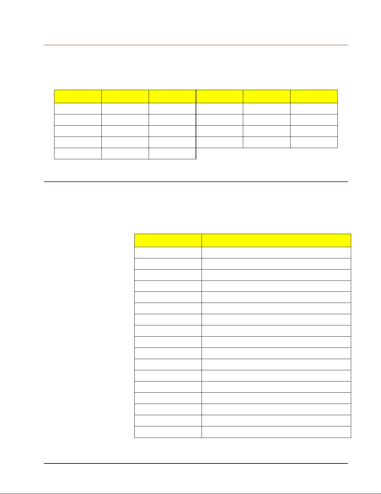
The following chart shows all possible memory configurations for the SBP-205.
SBP-205 Memory Configuration
RAM Bank 0 Bank 1 RAM Bank 0 Bank 1
64 MB 8M x 64/72 256 MB 32M x 64/72
128 MB 8M x 64/72 8M x 64/72 320 MB 32M x 64/72 8M x 64/72
128 MB 16M x 64/72 384 MB 16M x 64/72 32M x 64/72
192 MB 16M x 64/72 8M x 64/72 512 MB 32M x 64/72 32M x 64/72
256 MB 16M x 64/72 16M x 64/72
System Interrupt Chart
The processor has 2 controllers that supply a total of 16 IRQs. The following chart
shows IRQ assignments in order of decreasing priority.
System Interrupts
IRQ Function
NMI Parity error
IRQ0 Reserved, interval timer
IRQ1 Reserved, keyboard buffer full
IRQ2 Reserve, cascade interrupt from slave PIC
IRQ3 Onboard serial port 2
IRQ4 Onboard serial port 1
IRQ5 User available
IRQ6 Onboard floppy controller
IRQ7 Onboard parallel port
IRQ8 Real-time clock (RTC)
IRQ9 User available
IRQ10 User available
IRQ11 User available
IRQ12 Onboard mouse port if enabled, else user available
IRQ13 Reserved, math coprocessor
IRQ14 Onboard primary IDE disk controller
IRQ15 Onboard secondary IDE disk controller
• CSS Laboratories Section 4 – Technical References • 34
Page 39

•
IRQ9, IRQ10, IRQ11, IRQ12, IRQ15, IRQ3, IRQ4, IRQ5 and IRQ7 can be
redirected to PCI add-in boards.
The PCI standard has a 4-IRQ limitation. Some PCI add-in boards do not require
IRQs. Some can share an IRQ with another board of the same model and
manufacture. Check the add-in board documentation for IRQ information.
• CSS Laboratories Section 4 – Technical References • 35
Page 40

•
Notices and FCC Information
FCC Standards
The FCC (Federal Communications Commission) restricts the amount of radiation
and radio frequency emissions emanating from computing equipment.
Note: This equipment has been tested and found to comply with the limits for a
Class B digital device pursuant to Part 15 of the FCC Rules. These limits are
designed to provide reasonable protection against harmful interference in a
residential installation. This equipment generates, uses, and can radiate radio
frequency energy and, if not installed and used in accordance with the instructions,
may cause harmful interference to radio communications. However, there is no
guarantee that interference will not occur in a particular installation. If this
equipment does cause harmful interference to radio or television reception, which
can be determined by turning the equipment off and on, the user is encouraged to try
to correct the interference by one or more of the following measures:
Notice
Reorient or relocate the receiving antenna. Increase the separation
between the equipment and receiver.
Connect the equipment into an outlet on a circuit different from that to
which the receiver is connected.
Consult the dealer or an experienced radio/TV technician for help.
CSS Laboratories, Inc. is not responsible for any radio or television interference
caused by unauthorized modifications to this equipment. Operation with noncertified peripherals is likely to result in interference to radio and TV reception.
To ensure compliance to FCC non-interference regulations, peripherals attached to
this device require shielded I/O cables.
NOTICE: The use of a non-shielded I/O cable with this device is in violation of U.S.
Federal law and will not allow the device to meet the maximum emission limits.
CAUTION: Any changes or modifications not expressly approved by the grantee of
this device could void the user’s authority to operate the equipment.
The information within this manual is subject to change without notice.
CSS Laboratories, Inc., shall not be liable for technical or editorial errors or
omissions contained herein; nor for incidental or consequential damages resulting
from the furnishing, performance, or use of this material.
No part of this publication may be reproduced, stored in a retrieval system, or
transmitted, in any form or by any means, mechanical, photocopying, recording or
otherwise, without the prior written permission of CSS Laboratories, Inc.
Product names mentioned herein are for identification purposes only, and may be
trademarks and/or registered trademarks of their respective companies.
• CSS Laboratories Notices and FCC Information • 36
Page 41

•
Glossary of Terms
Adapter
A circuit board that plugs into the computer motherboard. Used to communicate with
a particular external device.
AGP
Accelerated Graphics Port. A connector on the motherboard for an accelerated
graphics controller card.
APM
Advanced Power Management. An interface developed to conserve power in a
computer system.
ATAPI
The interface used by the IBM PC AT system for accessing CD-ROM devices.
Backplane
A circuit board or framework that supports other circuit boards, devices, and the
interconnections among devices, and provides power and data signals to supported
devices
BIOS
Basic Input/Output System. A very basic set of instructions built into a computer that
tells it how to execute input and output instructions.
Bus
An electronic pathway on which electronic information travels between the
microprocessor and other computer parts.
Cache
A type of computer memory that is very fast in which the computer temporarily
stores information.
CD
Compact Disc. A nonmagnetic, polished metal disc with a protective plastic coating
that can hold large quantities of digital data.
• CSS Laboratories Glossary of Terms • 37
Page 42

•
CMOS
Complementary Metal-Oxide Semiconductor. 1. A semiconductor technology in
which pairs of transistors are integrated on a single silicon chip. Generally used for
RAM and switching applications, these devices have very high speed and extremely
low power consumption. 2. The battery-backed memory used to store information
needed to boot a computer, such as the type of disks and the amount of memory, as
well as the clock/calendar time.
Configuration
A particular arrangement of elements or features. The way in which these elements
are combined.
Configure
To prepare or customize hardware and/or software in a certain way.
Controller
One device that controls the operation and function of another. Typically, a
controller is a circuit board installed inside the computer to which external devices
such as monitors, printers or disk drives are connected.
CPU
Central Processing Unit. The “brain” of the computer, the chip that controls all
computer functions.
Default
In computer terms, the setting that will be used if you don't instruct the computer to
use something else.
DIMM
Dual Inline Memory Module. A type of memory chipset installed on the
motherboard.
DIN
Deutsche Industrie Norm. A multipin connector conforming to the specification of
the German national standards organization .
Diskette
A removable magnetic storage device encased in plastic. Also called a “floppy disk.”
DMA
Direct Memory Access. Memory access that does not involve the microprocessor
and is frequently used for data transfer directly between memory and an "intelligent"
peripheral device, such as a disk drive.
• CSS Laboratories Glossary of Terms • 38
Page 43

•
DMI
Desktop Management Interface. A system for managing the configurations and status
of PCs on a network from a central computer.
Driver
A special program that controls a device such as a mouse, CD-ROM or modem.
ECC
Error-Correcting Code. A code designed for transmission of electronic data so that
transmission errors may be detected and corrected at the receiving end.
EDO
Extended Data Out. A type of dynamic random access memory (DRAM) that allows
for faster read times than DRAM of comparable speed by allowing a new read cycle
to begin while data is being read from a previous cycle.
EIDE
Stands for Enhanced Integrated Drive Electronics. An extension of the IDE standard,
Enhanced IDE is a hardware interface standard for disk drive designs that house
control circuits in the drives themselves. It allows for standardized interfaces to the
system bus while providing for advanced features, such as burst data transfer and
direct data access. Enhanced IDE accommodates drives as large as 8.4 gigabytes
(IDE supports up to 528 megabytes). See also IDE, SCSI.
Ethernet
A local area network (LAN) standard that uses coaxial or twisted pair cable.
Hard Drive
A magnetically coated metal disk sealed in a box, used to store large quantities of
data.
I/O address
Input/Output address. The place in computer memory where data from devices is
read or written.
IDE
Integrated Drive Electronics or Intelligent Device Electronics. A type of interface for
controlling hard disk drives.
IRQ
Interrupt ReQuest. Used to let the computer know that a device is ready to do
something or that it has done something.
• CSS Laboratories Glossary of Terms • 39
Page 44

•
ISA
Industry Standard Architecture. A bus design that allows components to be added as
cards plugged into computer expansion slots.
Jumper
A pair of prongs that are electrical contact points set into a computer motherboard or
an adapter card. A small plastic plug placed on the prongs completes a contact in
order to alter an aspect of the computer configuration. A group of jumpers is called a
jumper block.
LAN
Local Area Network. A group of computers and other devices dispersed over a
relatively limited area and connected by a communications link that enables any
device to interact with any other on the network.
LED
Light Emitting Diode. A device that emits light when electricity passes through it.
LUN
Stands for Logical device or drive Unit Number. A device named by the logic of a
software system, regardless of its physical relationship to the system.
Menu
A list of options from which a user can make a selection in order to perform a
desired action.
MIS
Management Information Systems. Usually a department within a company that is
responsible for running and repairing computers and software.
Motherboard
The main circuit board of a computer to which most other devices connect. A single
board computer combined with a passive backplane form one complete motherboard
with extended processing, power and device connection capabilities.
Parallel
The transmission of data eight or more at a time; a type of device, such as a “parallel
port” that sends or receives data in this fashion. See also: Serial.
Passive Backplane
See Backplane.
• CSS Laboratories Glossary of Terms • 40
Page 45

•
PCI
Peripheral Component Interconnect A computer industry standard bus. See
also: Bus.
Peripheral
External equipment or devices connected to the computer. Examples include
monitor, printer, scanner, mouse and speakers.
Port
A jack in the back of the computer into which you can plug a peripheral device.
POST
Power On Self Test. This is the battery of tests the computer runs on itself when it
starts.
P/S2
A bus designed with Micro Channel Architecture as found in most IBM PS/2
computers. The Micro Channel functions as either a 16-bit or a 32-bit bus. The P/S2
bus can be driven independently by multiple bus master processors.
RAID
Stands for Redundant Array Of Independent Disks. A data storage method in which
data, along with information used for error correction is distributed among two or
more hard disk drives in order to improve performance and reliability. The hard disk
array is governed by array management software and a disk controller, which
handles the error correction. RAID is generally used on network servers.
RAM
Random Access Memory. The internal memory of the computer, stored on chips
installed on the Motherboard.
Reboot
To restart the computer. A “warm reboot” is done by pressing a reset switch. A
“cold reboot” is done by turning the machine off and then on again.
SCSI
Small Computer System Interface, often pronounced “skuzzy.” An industry standard
for connecting hard disks, tape drives and scanners to computers.
SDRAM
Synchronous Dynamic Random-Access Memory (DRAM). SDRAM can run at
higher clock speeds than conventional DRAM.
• CSS Laboratories Glossary of Terms • 41
Page 46

•
Serial
The transmission of data one bit after another in single file; a device that sends or
receives this kind of data transmission. See also: Parallel
Server
On a local area network (LAN), a computer running administrative software that
controls access to the network and its resources, such as printers and disk drives, and
provides resources to computers functioning as workstations on the network.
Single Board Computer
A computer that occupies only one circuit board, usually with no capacity for
additional boards.
Terminate
With reference to hardware, to install a plug, jack, or other connector at the end of a
wire or cable.
USB
Universal Serial Bus. A type of serial device connector.
VGA
Video Graphics Adapter. A video adapter that duplicates all the video modes of the
EGA (Enhanced Graphics Adapter) and adds several more.
• CSS Laboratories Glossary of Terms • 42
Page 47

•
Index
A
Adapter 16, 17, 23, 27, 29, 40, 42
B
Battery 4
BIOS 9, 11, 12, 13, 16, 17, 18, 23, 25, 28, 33,
37
C
Cache 1, 2, 3, 32, 37
CD-ROM 30, 31, 37, 39
CMOS 13, 14, 15, 16, 17, 18, 19, 20, 21, 26,
28, 33, 38
Connectors 2, 4, 5, 6, 7
D
DIMMs 2, 9, 13, 28
Diskette drive 4, 8, 19, 29
Diskette Drive 8
E
EIDE 1, 4, 6, 13, 19, 22, 33, 39
H
Hard drive 19, 30
I
I/O 6, 17, 25, 28, 36, 39
Interrupt See IRQ
IRQ 17, 25, 32, 34, 35, 39
ISA 1, 29, 32, 40
J
Jumper switches 2, 13, 14, 15, 16, 17
Jumper Switches 14, 15, 16
K
M
Maintenance 23
Memory 1, 2, 9, 10, 11, 17, 28, 31, 32, 34, 37,
38, 39, 41
Installing and Removing 10, 13, 28
Microprocessor See Processor
Monitor 27, 41
Mouse 1, 4, 5, 27, 33, 34, 39, 41
O
Operating System 1
P
Parallel port 1, 4, 7, 28, 33, 34, 40
PCI 1, 6, 12, 13, 17, 18, 19, 21, 29, 32, 33, 35,
41
Peripheral 1, 18, 33, 41
Peripherals 1, 22, 24, 33, 36
Power Management 18, 20, 37
Processor 1, 2, 4, 9, 11
R
Reset 13, 16, 17, 26, 41
S
SCSI 30, 39, 41
Serial port 4, 7, 8, 34
Serial Ports 7
System Utilities 24
T
Troubleshooting 23, 24, 25, 26
U
Universal Serial Bus See USB
USB 1, 8, 33, 42
Keyboard 1, 4, 5, 17, 19, 27, 33, 34
• CSS Laboratories Index • 43
Page 48

•
• CSS Laboratories Index • 44
 Loading...