

Page 1

Installation Manual
for CS2000
DualCom GSM Mk1 & 2
CSL DualCom Limited
Tel: 01895 474 474
Fax: 01895 474 440
Page 2

CONTENTS
Description 2
Part Numbers 3
Installation Procedure:
Site Survey 4
Installation 5
System Testing 6
Troubleshooting 8
Technical Support & Web Site 9
The Details:
Aerial Siting 10
SIM Card 12
DualCom Mounting 13
Security 13
CS1050 Expander Board 14
Fault & Aux Relay Output s 15
CS2366 Radio T est Set 20
Aerial Connection 21
T elephone Line Connection 22
Analogue PSTN T elephone Line Connection 23
P ABX, ISDN, Home & Business Highway 25
ADSL / ‘Broadband’ 28
The ‘Call Minder’ call answering service 30
System Power Supply & Battery 31
NVM Programming 32
SMS Sending 32
SMS Remote Control 33
Appendix 1 ( LED Indications ) 35
Appendix 2 ( Input Connections & Self Learning ) 39
Appendix 3 ( Specification & Regulations ) 43
Appendix 4 (Approvals ) 44
Appendix 5 (Glossary of Terms) 45
1
Part No.: AH 200002-012 10/7/2008
Page 3

DualCom GSM Mk1 & Mk2
Installation Manual
Description
DualCom GSM is an advanced auto-dialling Digital Communication Device for
secure alarm reporting. It can transmit alarm signals to an Alarm Receiving
Centre using the GSM, (Global System for Mobile Communications) data network or the PSTN (Public Switched T elephone Network). Dualcom can also be
programmed to send SMS (Short Message Services) to a GSM phone.
Where the installation is specified to the EN 50131 and PD6662 standards then
use of the DualCom GPRS is recommended.
DualCom GSM is supplied with a GSM SIM Card that is enabled for ‘Data’ and
‘SMS’ operation.
When DualCom GSM is triggered by the alarm system it initiates calls to the
Alarm Receiving Centre over both communication paths simultaneously . Once
it has received an acknowledgement signal from one path it clears the calls on
the other paths so that the Alarm Receiving Centre receives only one alarm
notification. Test calls are delivered using both paths to test the system fully.
DualCom GSM monitors both communication paths continuously. A fault on
one path is reported to the Alarm Receiving Centre using the other functioning
path. Any Alarm System bell delay is maintained unless both p aths are in fault,
or the Alarm Abort feature is used.
DualCom GSM comes complete with Alarm Abort feature to enable older alarm
systems to comply with the ACPO false alarm policy. Once the system is set,
if a mis-operation occurs and the system is unset within 90 seconds, a restore
on channel 3 or separate code will be sent to the Alarm Receiving Centre. If
programmed, a Tellback will also reset the control panel.
DualCom GSM is available as a stand-alone unit with screw-terminal inputs. A
tamper protected steel box with an integral power supply is also available.
DualCom GSM is housed in an ABS plastic case which protect s the electronics and meets PSTN safety requirements.
DualCom GSM has 8 alarm inputs. This can be expanded to 16 by adding an
Expander Board which also provides 8 outputs.
2
Page 4
Part Numbers
CS 2000 DualCom GSM (+ SIM Card, NVM & CS2058 aerial).
CS 1050 Expansion to 16 inputs & 8 outputs.
CS 2057 External Aerial with 5m lead (for internal or external use)
CS 2058 Box Aerial with 2.5m lead (for internal use only)
CS 2366 GPRS/GSM Radio Test Set
CS 1520 T amper protected Grade 2 Power Supply .
CS 1530 T amper protected Grade 3 Power Supply .
CS 2055 Box of 10 NVM, type CS93C66
CS 0300 Heavy Duty Lightning/Surge Suppressor
CS 0730 Security ADSL Filter
CS 0054 Programmer & Downloading software.
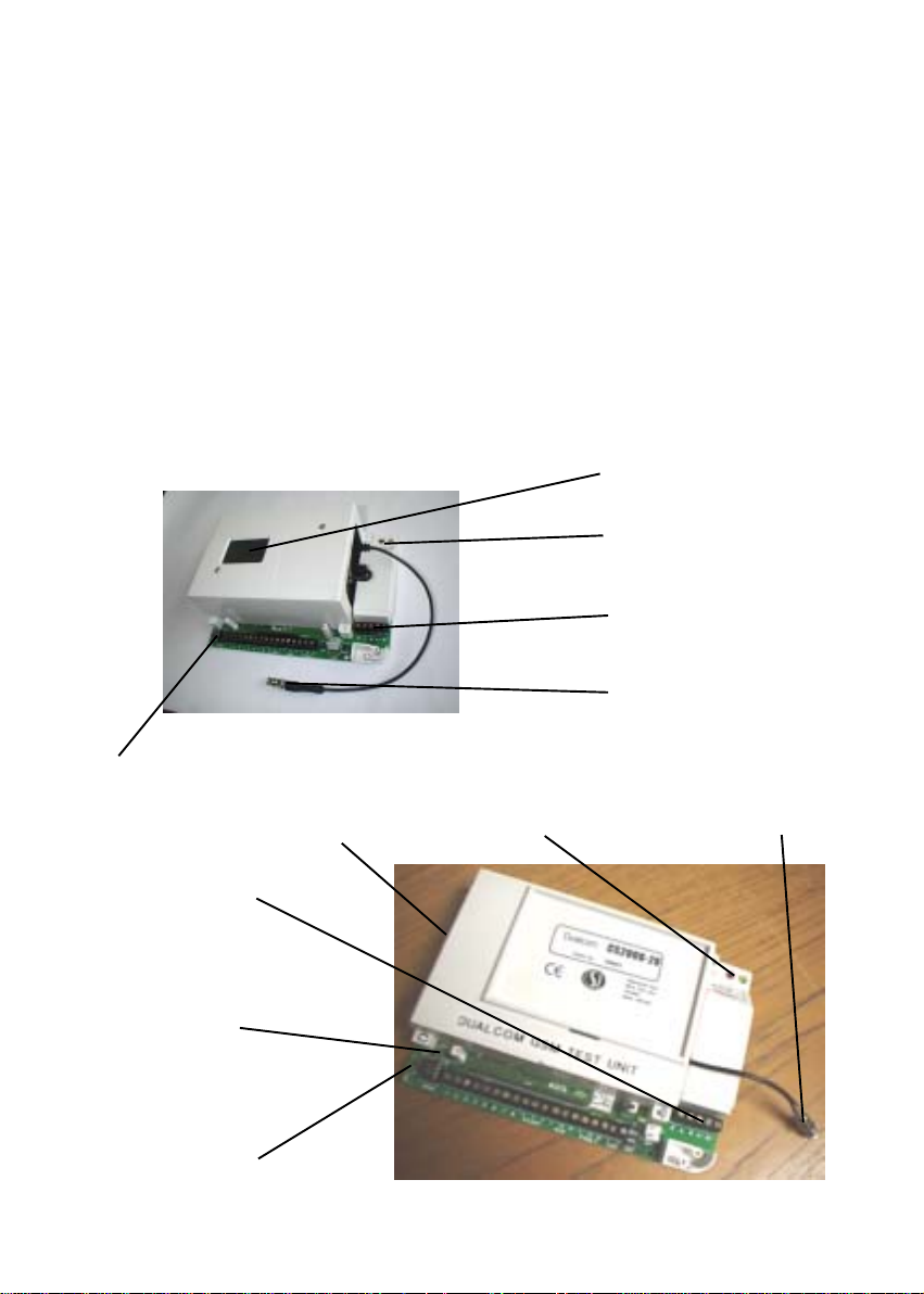
SIM Card Socket
Red & Y ellow
Communication LEDs
PSTN T elephone
Connections
GSM Aerial
Connector
DualCom GSM Mk1
Red & Green
Signal Strength
LEDs
Fig 1
SIM Card Socket
Red & Y ellow
Communication LEDs
GSM Aerial
Connector
PSTN T elephone
Connections
Status LED
Red & Green
Signal Strength
LEDs
3
DualCom GSM Mk2
Page 5
Site Survey
It is strongly recommended that a site survey is conducted prior to installation of a DualCom GPRS to confirm that adequate GPRS signal
strength is available at the site.
Before visiting the site, call CSL Technical Support. See page 9. Ask for a
GPRS signal strength prediction. For this, you will need to have the Post Code
of the site available. This will tell you if there is GPRS radio coverage at the
proposed site.
DualCom GSM is supplied with a Vodafone UK GPRS SIM Card which
can only be used in UK on the V odafone UK GSM and GPRS networks.
If there is no GSM radio coverage at the proposed site, the DualCom’s GSM
and GSM radio alarm reporting paths will not operate.
Use of the CS2366 GSM/GPRS Radio T est Set is recommended to survey the
proposed site for GSM/GPRS signal strength and to locate the point of strongest signal. See Aerial Siting on Page 10 for more information. Make a note of
this point and use it when installing the Dualcom aerial.
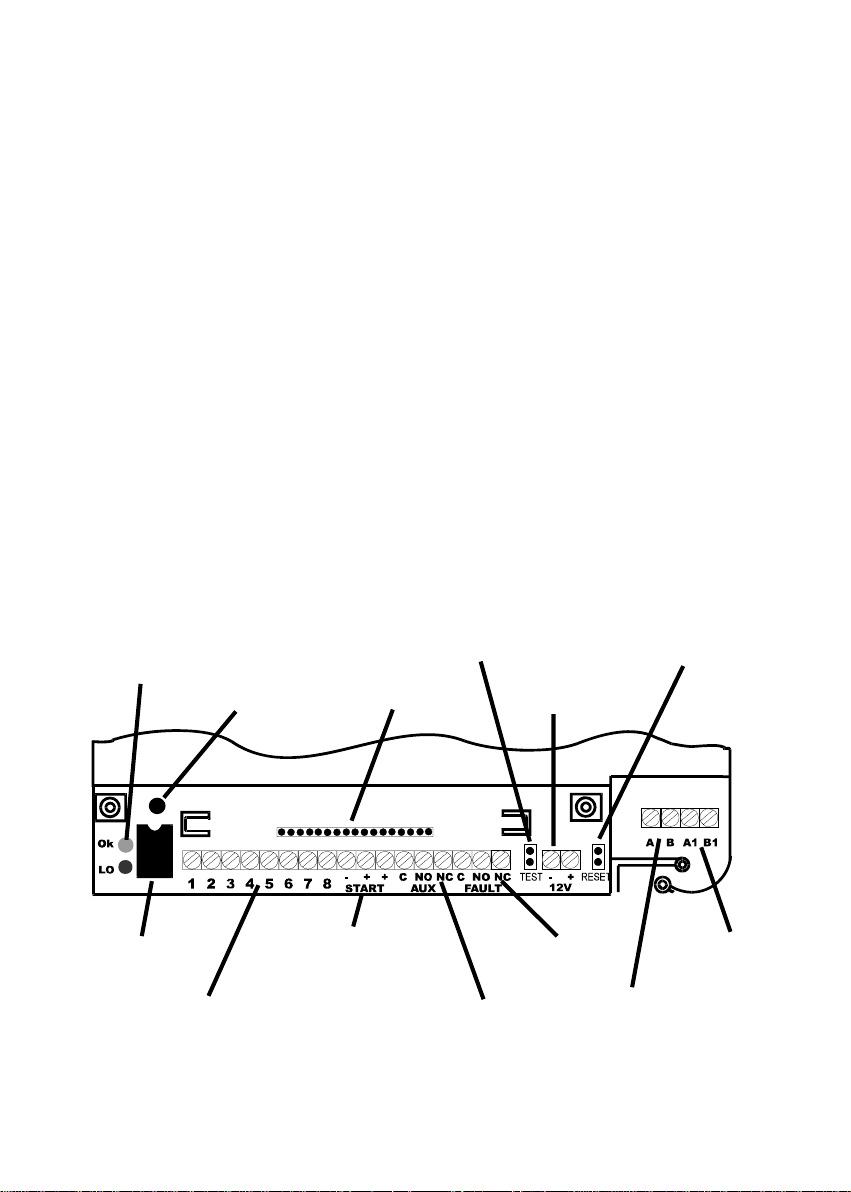
Red & Green Signal
Strength LEDs
Status LED
NVM socket
8 input terminals
Socket for
Expansion units
Positive (pull-up) and
0volt source for input
triggering
Fig 2
4
Test Pins
Aux relay
terminals
12 volt power
connections
Fault relay
terminals
PSTN Line
A & B terminals
Reset Pins
A1 & B1
terminals
Page 6

Installation
1. Site the aerial at the point of strongest signal ensuring that it is within the
protected area. This is usually the highest point in the building and well
away from metal roofs and metal walls. See Page 10.
2. Program the NVM for the system specific requirements or obtain a programmed NVM from your Alarm Receiving Centre. See p age 32.
3. Ensure that a GSM SIM Card is fitted in the DualCom. See page 12.
4. T ot ally power down the control panel mains and battery .
5. Fit the NVM into the 8 pin socket located at the front of the DualCom. See
Fig 1 & 2.
6. Where required, fit the CS1050 Expansion board, See page 14.
7. Connect the input triggers to the DualCom. See page 12 and Appendix 2.
8. Connect to the relays “Fault” and “Aux” as required. See page 15.
9. Connect the aerial to the DualCom aerial lead using the threaded connector
provided. See Fig 1.
10.Connect the PSTN line to the terminals provided under the protective cover.
For security installations, only ‘serial connection’ is recommended for other
equipment that is using the same line . See Pages 22 to 30.
1 1. On the DualCom, connect the ‘12v +’ & ‘12v -’ terminals to the Control Panel
or Power Supply 12 volt output (often called ‘Aux supply’ or ‘DC power’).
See Fig 2 and page 31.
DO NOT supply power to the DualCom directly from the battery because this may bypass the current limited charging circuits found in
many modern power supplies.
The ‘Start’ ‘+’ & ‘-’ terminals next to the 8 input terminals are to assist
input triggering only . These terminals are not the supply connector.
12.Note the SIM Card number, NVM ‘chip’ number (and any security access
numbers) on the site records that will be stored at your office.
13.Reconnect the mains supply to the control panel. The DualCom is now
ready for testing.
5
Page 7

System T esting
Ensure you have informed your Alarm Receiving Centre that you are
ready to test your DualCom.
Note: If the NVM is an incorrect type, is faulty, fitted incorrectly or has been
incorrectly programmed (including being blank or un-programmed), then the
Red and Y ellow Communication LEDs will flash alternately .
If there is a problem with the SIM Card or the GSM radio module, the Yellow
Communication LED will flash. If there is a problem with the PSTN telephone
line, the Red Communication LED will flash. See Appendix 1.
1. Power up the DualCom, the unit will initialise. This will take 20 seconds with
the GSM LED On, the PSTN LED Off, and the Signal S trength LEDs Off.
When ready, the GSM Status LED will flash on/off slowly and the Signal
Strength LEDs will show the signal strength,
2. T o test both reporting paths to the ARC, momentarily short the test pins on
the DualCom see Fig 1 & 2. This will cause DualCom to send a test signal
to the ARC on both the PSTN telephone p ath and GSM radio path.
Once the test pins are shorted the two communication LEDs will illuminate,
(Red for PSTN and Y ellow for GSM). During communication the LEDs will
flash to indicate the progress of the call, see Appendix 1. When a p ath has
successfully communicated with the ARC, the associated LED will go off.
Both paths will send a test call. The Alarm Receiving Centre should receive
two test calls
Ensure after the test that both LEDs are off; this will mean that the test calls
on both paths are complete.
3. Now trigger all the used inputs on the DualCom. This should be done by
Setting the Control Panel and triggering an alarm condition. If P/A or Fire
circuits are being monitored these should also be triggered.
Note : When alarm calls are made, both GSM and PSTN paths are
activated, but only one alarm call will be received. This will be from
the path that is the first to send the alarm call to the ARC.
4. Contact your ARC to confirm that all signals have been received. Ensure
that all ‘Restore’ signals are received when the DualCom input terminals
return to their quiescent value.
6
Page 8

System Testing (continued)
5. If the quiescent (non-active) states of the input terminals are incorrect, i.e.
‘positive applied/removed is inverted, then the ARC will report that the Alarm/
Restore or Open/Close is the ‘wrong way round’. To correct this, use the
Self Learning Input feature. See Appendix 2.
6. If you are using SMS signalling, check that the relevent message(s) has
been received on the GSM phone(s).
7. If at any time you wish to cancel a call, short the Reset pins. See Fig 1 & 2.
8. If you are using the Alarm Abort feature, set the Alarm Panel, initiate an
alarm condition and (If the alarm system incorporates bell delay this will be
overridden) then unset the alarm system within 90 seconds.
Check that the alarm abort signal has been sent to the ARC and, if selected,
the alarm system has reset.
9. Remember to note the SIM Card number , NVM ‘chip’ number (and any security access numbers) on the site records that will be stored at your office.
10.Your DualCom is now fully tested.
7
Page 9

Troubleshooting
Q. What if there appears to be random triggering of the DualCom ?
Ensure that 0 volts is common across all parts of the alarm system.
If the DualCom receives its power from a Power Supply that is additional
to the alarm system, ensure that the 0 volt connection on the additional
power supply is connected to the 0 volt connection on the alarm system.
Q. What if the Digital Communicator signal is not received by the Alarm
Receiving Centre ?
Check that the NVM is fitted and has been correctly programmed, i.e. PSTN
enabled, correct telephone numbers.
Check that the PSTN line is properly connected. Check with a meter that
approximately 50 volts DC is present across the PSTN terminals marked A
and B. Connect a telephone to the PSTN line and make a call to ensure
that it is fully functional. Remove telephone after test.
Ensure that ‘call barring’ to the ARC Receiver telephone number has not
been set on the PSTN line used by DualCom by using a phone and dialling
to the ARC receiver(s). Remove telephone af ter test.
Disconnect any other equipment that is using the same PSTN line to ensure that it is not inhibiting the DualCom.
Check that when the DualCom is triggered, the voltage across the A and B
terminals drops to between 6 and 12 volts DC.
See Appendix 1 for Line Monitoring indications. These will help diagnose
line problems.
Q. The Fault Relay does not operate so that EN Standards can be met ?
Where the installation is specified to the EN 50131 and PD6662 standards
then use of the DualCom GPRS is recommended.
8
Page 10

Troubleshooting (continued)
Q. What if the GSM signal has not been received by the Alarm
Receiving Centre ?
Check that the NVM is fitted has been correctly programmed.
Check that the SIM Card is fitted has been correctly programmed
i.e it is enabled for ‘Data’.
Check, using the Signal Strength LEDs (Red & Green) that the radio
signal is sufficient and the GSM path status = OK.
Check with a meter that the voltage supply to the Dualcom is 13.6v or
more and does not dip when the DualCom is signalling.
See Appendix 1 for GSM fault indications. These will help diagnose
radio path problems.
Technical Support & Web Site
If you have installed the DualCom in accordance with these instructions, checked
all the above points but are still experiencing problems you can contact your
DualCom supplier.
In UK, DualCom installation, programming, operation or other questions may
be addressed to:
The CSL Technical Support Desk:
T el: 01895 474 444
Email: support@csldual.com
Hours: 08.00 to 18.00 weekdays
The CSL web site: www.csldual.com contains the latest copies of all manuals
for all CSL products. Please ensure that you are working from the latest version. You can also download associated information and software samplers.
Sales, shipping and contact information is here too.
For Vodafone GSM/GPRS radio signal strength predictions in UK using the
postcode of the proposed installation site, use the CSL web site link:
http://www.csldual.com/coverage Select Map Type = Mobile Data Map, and
Mobile Data Coverage = St andard Services.
9
Page 11

Aerial Siting
ALWAYS do a site survey to find an area of strong signal before inst allation.
Installing DualCom with a weak signal is bad installation practice. The DualCom
is likely to suffer signal failure, causing wasted site vists, wasted time & money .
The aerial should be mounted vertically at the point of strongest signal. This
is usually the highest point in the building (often the loft area).
Large metal structures can affect radio signals. Avoid installing the aerial
directly under metal roofs or within metal skinned buildings because this will
reduce the signal strength and may inhibit operation completely . If this
is unavoidable, the strongest signal will be found away from the metal roof or
close to large external windows or skylights.
Avoid installing the aerial close (2 metres) to cable runs, ducting, structural
metalwork, metal pipes, water tanks and electronic equipment, e.g. photocopiers, fax machines etc. These can have similar effects as metal roofs.
The Signal Strength LEDs on the front of the DualCom (see Fig 1 & 2 and
Appendix 1) will give an indication of signal strength that DualCom is receiving
from the GSM Network. Note: These will not work with an unprogrammed NVM.
Green On: High Signal Strength
Red & Green On: Medium Signal Strength
Red On: Low Signal Strength
Reliable operation is unlikely with a low signal strength. If the display shows
that the signal strength is low, you should improve the signal strength. This
may be achieved by repositioning the aerial. The GPRS aerial lead should not
be cut or extended, therefore repositioning the aerial may require that the
DualCom is also repositioned.
A site survey should provide information on the availability , signal strength and
interference status of all radio Base St ations in the surrounding area.
The CS2366 Radio T est Set is ideal for surveying a site. This handheld unit can
check the availability , signal strength and interference status of all surrounding
Base Stations. In addition, it will identify the best location for a DualCom GPRS
aerial within the building, it will help to avoid sources of interference and can
confirm the availability of a GPRS service at the proposed site.
Where a CS2366 Radio Test Set is unavailable, a DualCom GPRS, aerial and
fully charged battery may be used to locate the point of strongest signal. Ensure that the DualCom is fully operational then walk around the site carrying the
equipment observing the signal strength display .
10
Page 12

Aerial Siting
This ‘DualCom, aerial & battery’ method can not provide information on the
availability , signal strength and interference status of all radio Base S tations in
the surrounding area. Use of the CS2366 Radio T est Set is recommended.
Alternatively, a Vodafone mobile phone may be used to locate the point of
strongest signal. The signal strength indicator is normally a bar or line at the
side of the display on the mobile telephone. Note: The mobile phone MUST
use the Vodafone network. A mobile phone that uses a different radio network will NOT show the correct signal strength.
This ‘mobile phone’ method can not provide information on the availability , signal strength and interference status of all radio Base St ations in the surrounding area. Use of the CS2366 Radio Test Set is recommended.
When you have identified the point of the strongest signal, make a note of this
point and use it when installing the DualCom aerial.
Remember: It is always easier to find the point of strongest signal before the
equipment is fitted to a wall. Moving aerials, cables, trunking etc. after installation is wasted time and effort.
11
Page 13
Sim Card
DualCom GSM is supplied with a suitable GSM SIM Card. Check if a GSM SIM
Card has already been fitted in the DualCom GSM.
The SIM card has a number printed on it. This is the SIM Card Serial Number .
It is recommended that this number is recorded on the site records that will be
stored at your office.
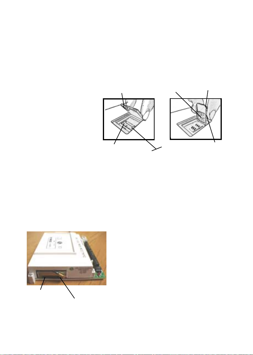
DualCom GSM Mk1.
Slide open & lift out the grey
cover on the top of the
DualCom. Slide the silver bar
to the ‘open’ position and lift
the hinged flap. Wipe the
gold contacts with a clean
tissue or cloth. Do not
touch the the gold contacts with fingers. Slide
the SIM card into the slot
on the hinged flap with the
cut corner up so that the SIM
Card gold connectors will
face down when the flap is
lowered.
Replace the grey cover. Lower the flap. Slide the silver bar to the
‘lock’ position.
SIM Card
carrier
GSM DualCom Mk2 SIM Card
SIM Card
Eject button
Fig 4
Cover
Silver Bar
DualCom GSM Mk2.
Using a ball-pen or pencil, push the black
or yellow ‘eject’ button. The SIM Card Carrier will slide out of the DualCom. Fit the
SIM card into the SIM Card Carrier with
the gold contacts uppermost. Wipe the
gold contacts with a clean tissue or
cloth. Do not touch the the gold contacts with fingers. Slide the SIM Card
Carrier into the DualCom. Ensure it is
pushed fully in.
Gold
Connectors
Locked
Open
GSM DualCom Mk1 SIM Card
Fig 3
Cut Corner
Hinged
Flap
12
Page 14

DualCom Mounting
DualCom may be mounted in a boxed power supply or other suitable case. The
CS1520 and CS1530, grade 2 and 3 power supplies are ideal for this. The case
has mountings and screw retainers for a DualCom, space for 7 amp/hour battery(s)
and plenty of room for wiring.
Alternatively, any suitably sized case that meets the security requirements
may be used. DualCom has two mounting lugs fitted to its case for screw
fixing.
Security
Note: Up/downloading security features are NOT activated when
DualCom is supplied. Use of one or more of these features is recommended.
DualCom should be protected from assault and tampering by being fitted inside
a tamper protected enclosure that is part of the alarm system.
The DualCom has two independent methods of stopping unauthorised up/
downloading. These security features are for up/downloading only . They do not
operate when the NVM is removed from the DualCom and is plugged into an
NVM Programming Socket connected to a PC.
A ’call-back’ GSM number may be programmed so that the DualCom always
calls to its preset ’call-back’ engineering number whenever up/downloading is
requested.
A 6 digit access code may be programmed so that the DualCom always
requires this code whenever up/downloading is requested. CSL strongly rec-
ommend that this feature is used.
In addition, up/downloading can be inhibited when the alarm system is in the
set state.
Note: Up/downloading security features are NOT activated when
DualCom is supplied. Use of one or more of these features is recommended.
13
Page 15

The CS1050 Expander Board
The CS1050 is a plug-on board that adds an additional 8 inputs and 8 outputs
to the CS1000 and CS2000 range of DualComs.
To install:
1. Remove power to the DualCom when fitting or removing the CS1050 Expander
board.
2. Slide the CS1050 Expander into the two
guides on the DualCom with the white connector towards the DualCom board. Push
Fig 5a
3. Connect the triggering inputs to the INPUT terminals labelled 9 to 16, as
required. See page 12 and Appendix 2.
4. Connect the outputs to the OUTPUT terminals, labelled 1 to 8, as required.
These outputs are ‘open collector pull-down’ to 0v. Each will supply up to
50mA and may operate lights or relays with a supply up to +28 volts. Where
relays are connected, they should be fitted with a diode across their coil to
reduce ‘back EMF’ voltages. See Fig 5b.
the CS1050 down to ensure it connects
fully . See Figs 1 and 2.
Note: If you use a separate Power Supply, remember to connect the 0v
terminals of all of the parts of the system.
The CS1050’s outputs can be remotely controlled via the radio path using
the CS2054 Programmer software and by SMS messages from a mobile
phone. See page 33.
5. The DualCom NVM will need to be
programmed for ‘16 channels’ enabled. Y our ARC may provide a programming service. Alternatively,
contact the CSL Technical Support
Desk. See page 9.
All of the normal input programming
options apply to the CS1050 Expander .
These are: Positive applied / removed triggering, self learning, restore reporting, open/close reporting, radio failure report and PSTN failure report.
14
Relay
Diode
CS1050
o/p
0 v
Power
Supply
Fig 5b
+VE
0 v
Page 16

Fault & Auxilliary Relay Outputs
The Fault and Aux relays operate when the DualCom has fault and other conditions.
Where the installation is specified to the EN 50131 and PD6662 standards then
use of the DualCom GPRS is recommended.
For compatiability with older Control Panels, the ‘Normal’ mode of operation is
supplied. See Fig 7
tluaF etatsyaDnilenaP etatsteSnilenaP
tluafhtapNTSP
ylno
tluafhtapoidaR
ylno
dnaNTSPhtoB
tluafhtapoidaR
lufsseccusnu3
NTSPnostpmetta
lufsseccusnu01
NDVnostpmetta
&NTSPliaflatoT
NDV
suounitnoC esluPdnoces2 noitcayalertluaFoN
suounitnoC esluPdnoces2 noitcayalertluaFoN
suounitnoC suounitnoC suounitnoC
esluPdnoces2 esluPdnoces2 esluPdnoces2
esluPdnoces2 esluPdnoces2 esluPdnoces2
suounitnoC suounitnoC suounitnoC
ni+etatsteSnilenaP
mralA
Fig 7
Aux Output
The Aux relay cont acts, C, NO and NC can be programmed to :
a) Change state if a tellback signal is generated by the alarm abort sequence
or is sent to the DualCom from a remote centre, OR...
b) Change state when the DualCom has successfully communicated with the
ARC, OR...
c) Change state when DualCom has been sent an SMS message from a
mobile phone. See page 29 for SMS Remote Control information.
Refer to the CS2054 Programmer Manual for full programming information.
15
Page 17

P AGES 16 - 19
LEFT INTENTIONALL Y BLANK
Page 18

GPRS/GSM Radio T est Set
The CS2366 is a Radio T est Set for use
with GPRS and GSM Radio Networks
and the CS2000, CS2300 and CS4300
range of DualComs.
It may be used to aid positioning and
the testing of GPRS and GSM aerial
systems.
The T est Set will measure and display
radio signal strength received, plus the
level of interference may be measured
and sources of interference identified.
The Test Set contains a battery allowing remote operation for up to 12 hours.
The internal battery may be recharged
from the supplied mains power supply .
The Test Set is contained within a
strong protective sleeve It is supplied
complete with a charger, aerial and
manual, and is covered by a no-quibble
‘unit exchange’ 2 year guarantee.
20
Fig 6
Page 19

Aerial Connection
The Box Aerial is supplied with 2.5 metres of coax lead and is for internal
mounting only . Do not cut, rejoin or lengthen the lead.
If the signal strength is insufficient, relocate the aerial and (if necessary) also
relocate the DualCom, extending the bus wiring and other leads as required.
An optional extra CS2057 aerial is available with a 5 metre lead. This item is
weartherproof and may be mounted externally where installation standards allow. Connect as shown below .
T o mount, open the CS2058 case and fit screws through the case rear .
Top
Bottom
Plug the
aerial lead
connector
into the
DualCom
Aerial
Aerial Lead
Fig 7
Aerial Lead
Install the aerial
upright with the
lead exiting the
case at the bottom.
DualCom
SIM Card
21
Page 20

Telephone Line Connection
There are several different types of telephone line available from different service
providers.
DualCom requires an analogue telephone line connection. ‘Earth Loop Calling’ or ‘Earth Calling’ types of analogue telephone line can not be used.
DualCom can not be directly connected to any type of digital telephone line.
For Broadband connection see page 28.
Earth connection
DualCom does not require an Earth connection at the telephone line terminals
as per EN regulations. See item 4, page 24.
Analogue PSTN Telephone Line
The analogue PSTN is a communication network where the line from the exchange equipment and the service supplied to the subscriber is ‘analogue’, i.e.
not ‘digital’. See Fig 8.
A telephone line is always terminated at the users premises by an NTP (Network Termination Point) which is provided by the telecoms Service Provider.
This is a socket or connection where the users equipment can be connected.
Some NTPs provide a socket and terminals for connection. In many cases,
the NTP operates using power supplied from the exchange equipment via the
telephone line.
An analogue PSTN telephone line may be provided by BT or any of the other
44 telecomms service providers in UK. DualCom can be connected to any of
these company’s PSTN analogue lines.
Analogue PSTN T elephone Line
Fig 8
22
Page 21

PSTN Line Connection Options
DualCom’s PSTN connection requires an analogue telephone line. Where
the analogue telephone line also carries ADSL (Broadband) signals refer to
ADSL later in this section.
Connecting other telecoms equipment IN PARALLEL to the analogue
telephone line used by DualCom can stop the unit sending alarm calls
to an Alarm Receiving Centre. Parallel connection should NOT be used
for DualCom when it is used in a security system.
There are several ways that a DualCom may be connected to a PSTN telephone line particularly when other equipment needs to share the same telephone line. Some require that your T elecom Service Provider supplies particular line features. Some require NVM programming options.
The highest security PSTN line for DualCom (Recommended):
A PSTN line supplied as ‘outgoing calls only’, i.e. Incoming Ringing Barred,
AND the PSTN line is ex-directory ,
AND the PSTN line goes to the DualCom ONL Y. Other equipment can be
connected to the DualCom A1 & B1 terminals (i.e. series connection) to make
outgoing calls only . See next page.
The next best security option for a PSTN line (Recommended):
A PSTN line supplied with the ‘3-way calling’ feature,
AND the DualCom NVM is programmed for ‘3-way calling’,
AND the PSTN line goes to the Dualcom ONL Y. Other equipment can be
connected to the DualCom A1 & B1 terminals (i.e. series connection) for incoming and outgoing calls. See next page.
The ‘no security’ option ( NOT Recommended ):
The PSTN line is supplied without ‘outgoing calls only’ or the ‘3-way calling’
feature. This option can not cancel or ‘hold’ incoming calls and these will
inhibit DualCom from making a telephone call to the Alarm Receiving Centre.
Parallel Connection ( Do NOT use ):
The DualCom A & B terminals connect to the telephone line, and other equipment connects directly
to the same telephone line.
This connection option can not cancel or ‘hold’ in-
coming or outgoing calls and these will inhibit
DualCom from making a telephone call to the ARC.
23
Page 22

PSTN Line Connection (DualCom ALONE on line)
Y our Telecom Service Provider should be asked to supply and fit an analogue
line and an NTP with terminals near the alarm system. The alarm installer
should then follow steps 1 and 2 below. See Fig 9.
Series Connection (DualCom & OTHER EQUIPMENT on line)
Y our Telecom Service Provider should be asked to supply and fit an analogue
line and an NTP with terminals near the alarm system. The alarm installer
should then follow steps 1, 2 and 3 below . See Fig 10.
1. Use cable type 1/0.5mm CW1308, feed through the cable entry , connect
the cores to the DualCom terminals marked A and B.
2. Connect the other end of the cable to the T erminal Block connections for the
incoming telephone line, marked A & B, or 2 & 5.
3. If the PSTN line used by DualCom is shared with other customer apparatus
(e.g. telephone, fax or answer machine) connect the terminals marked A1
and B1 on the DualCom to a PSTN Master Socket. The customer may then
plug their phone, fax etc, into that socket.
A PSTN Master Socket type LJU2/4A is suitable and has screw terminals
for connection. These can be obtained from many electrical distributors including:
CP C Part Number: TE 05285
Farnell Part Number: 916-638 or 101-3290
Maplin Part Number: FT48C
Rapid Part Number: 24-01 16
RS Part Number: 472-534
Fig 9 Fig 10
4. Earlier versions of DualCom GSM were supplied with an E or Earth terminal
next to the PSTN A & B terminals. In this case, connect a 1.0mm earth
cable to Terminal E. Ensure that the other end of this earth cable is connected to a good ground earth. This protects the equipment from high voltages,
e.g. lightning, that may strike the telephone line.
24
Page 23

P ABX (Private Automatic Branch Exchange)
A PABX is a telephone exchange in one business or building (where a dial 9 is
needed for an outside line). It connects to one or more outside telephone lines
and has two or more extentions within the business or building. See Fig 1 1.
DualCom may be connected to one of the outside telephone lines where they
are the analogue PSTN type.
The extentions within the building may be analogue or digital. Where an extention
is analogue, a normal phone or fax machine may be connected. DualCom
may be connected here. See Fig 12.
Where the P ABX is mains powered and it is not battery backed-up then the line
to the DualCom may fail in the event of a mains failure. This may make this
type of telephone connection unsuitable for DualCom.
Where the extention is a digital line then a special ‘feature phone’ is usually
required, provided by the manufacturer of the P ABX equipment. DualCom can
not be directly connected to any type of digital telephone line.
P ABX with connection to Analogue PSTN Line
Fig 1 1
25
Page 24

P ABX (Private Automatic Branch Exchange)
P ABX with Analogue extension
Fig 12
ISDN (Integrated System Digital Network)
The digital ISDN is a communication network where the line from the exchange
equipment and the service supplied to the subscriber is ‘digital’, i.e. not ‘analogue’. An ISDN line can carry several calls simultaneously.
A ‘primary rate’ or ISDN30 line can carry the equivalent of up to thirty simultaneous calls. This type of digital teltephone line normally connects directly to a
P ABX telephone exchange. See Fig 12.
A ‘basic rate’ or ISDN2 line can carry the equivalent of two simultaneous calls.
An ISDN line is always terminated at the users premises by an NTP (Network
T ermination Point) which is provided by the telecoms Service Provider . The NTP
is a socket or connection where the users equipment can be connected.
In many cases, the ISDN NTP operates using power supplied from the exchange equipment via the ISDN telephone line, however some types of NTP
may require a connection to the mains supply at the users premises, e.g.
Business & Home Highway .
Where the NTP is mains powered and it is not battery backed-up then the line
to the DualCom may fail in the event of a mains failure. This may make this
type of telephone connection unsuitable for DualCom.
26
Page 25

Home Highway , Business Highway
Home Highway or Business Highway is the marketing name for a ‘basic rate’
ISDN2 line supplied by BT with an NTE9 NTP.
The NTE9 NTP provides two digital sockets, it includes an ISDN-Analogue converter and two analogue telephone sockets. This type of NTP can have an
analogue phone, fax, modem etc. connected at either or both of the analogue
telephone sockets.
Power for the NTE9 comes from the exchange equipment via the ISDN line and
also from the mains supply at the users premises.
In the event of mains failure, the right-hand analogue telephone socket on the
NTE9 will cease to operate but all other functions are powered from the exchange equipment. It is important therefore to connect DualCom to the left-
hand analogue telephone socket on the NTE9. See Fig 13.
A maximum of two calls on an NTE9 may be in progress at the same time. If
two calls are in progress it is impossible to make another outgoing call or
receive another incoming call.
The ‘two call maximum’ means that if two calls are in progress then any other
calls in or out can not be made. This limit may make this type of connection
unsuitable for DualCom.
ISDN2 Home & Business Highway
Fig 13
27
Page 26

ADSL (Asynchronous Digital Subscriber Line) or ‘Broadband’
When an analogue PSTN telephone line also carries ADSL (Broadband)
signals and it is used by a security system e.g. DualCom, then a Security
ADSL filter MUST be used.
A filter is used to separate the analogue telephone signals from the ADSL
(Broadband) digital data signals because the phone or security system may
be disrupted or completely inhibited if ADSL (Broadband) digital data is
allowed into them from the telephone line.
The CSL CS0730 Security ADSL Filter is designed specifically for use with
security systems. It includes spare terminals to aid wiring that are labelled
‘Pass Through’. This item meets all of the requirements of the British and European telephone and security standards. See Fig 15.
Other types of filter and plug-in filters should not
be used for Series Connection of a security system to the telephone line. Plug-in types are for
use with telephones, fax machines etc. Plug-in
filters are available from the T elephone Service Provider and many electrical distributors including:
CP C Part Number: TE 05454 or TE04070
Farnell Part Number: 418-5328 or 506-0205
Maplin Part Number: A61AK or A72AG
CS0730
Serial Connection to a PSTN (and Broadband)
telephone line is shown in Fig 16.
The installer must ensure that:
1. The user’s telephone wiring is disconnected from the NTP and reconnected to the CS0730 ADSL Filter only.
2. The NTP connects only to the CS0730 ADSL Filter and to no other
wiring or telephone sockets.
3. The wiring between the NTP and the the CS0730 ADSL Filter can not
be unplugged by the user.
4. The user can not plug a phone/fax etc. into the NTP.
5. The terminals 2,3 & 5, A & B and A1 & B1 are connected exactly as
shown in Fig 16.
28
Security ADSL Filter
Fig 15
Page 27

ADSL (Asynchronous Digital Subscriber Line) or ‘Broadband’
DUALCOM
PSTN Connection
using the
CS0730 Security ADSL Filter
Fig 16
Q. Why is a Broadband Filter necessary ?
A. When ADSL (Broadband) digit al data is supplied on a normal PSTN tele-
phone line then an ADSL (Broadband) Filter must be fitted between that telephone line and each item of ‘non digital’ equipment because:
1). The operation of ‘non digital’ equipment may be disrupted or completely
inhibited if ADSL (Broadband) digital data is allowed into it from the telephone
line.
2). The operation of the ADSL (Broadband) equipment may be disrupted or
completely inhibited by the connection of unfiltered ‘non digital’ equipment to
the telephone line.
‘Non digital’ equipment means anything that can be used on a normal analogue
PSTN telephone line, e.g. a Phone, Fax, DualCom, Control Panel Digi-Modem.
29
Page 28

The ‘Call Minder’ call answering Service
Some telecom Service Providers offer a call answering service. This will answer
incoming calls if the subscriber’s telephone is not answered within a number of
rings.
This service indicates to the subscriber that an earlier call has been recorded
and should be heard by pulsing the dial-tone on subsequent calls. See the
table below .
enoTlaiD gninaeM sllaCderewsnA
suounitnoC
desluP
laidyamuoY sllacderewsnaoneraerehT
laidyamuoY
gnitiawsllacderewsnaeraerehT
draehebot
To ensure correct operation,.the DualCom’s NVM must be set to 0.1 second
dial-tone detection. Contact CSL Technical Support for more information.
30
Page 29

System Power Supply and Battery
DualCom requires a supply of 13-13.8 volts DC at 75mA in standby and 150mA
when activated.
The installer must ensure that the Alarm System power supply(s) is rated to
provide adequate power for this apparatus and for any other apparatus draw-
ing power from the Alarm System power supply(s).
Only power supplies conforming to EN60950, EN41003 or International Safety
St andards and carrying the CE mark should be used with this apparatus.
The Power Supplies’ battery must be suitable to support operation for the specified time. Refer to the EN50131 Power Supply standard for the Grade of the
instalation.
If DualCom receives its power from a Power Supply that is additional to
the alarm system, ensure that the 0 volt connection on the additional
power supply is connected to the 0 volt connection on the alarm system.
If the supply voltage falls to the ‘low battery voltage’ limit, the DualCom will send
a ‘low-battery signal to the ARC. When power is restored above 12.0 volts a test
call (or battery voltage restore signal) will be sent to the ARC. If the supply
voltage continues to fall below 10 volts there will be insufficient power to operate
the unit and the power supply battery may suffer permanent damage.
Note: The ‘Start’ ‘+’ & ‘-’ terminals next to the 8 input terminals are voltage
outputs to aid input triggering only. These terminals are NOT the supply
connector. See Fig 2 & 17.
Power Supply or
Control Panel
Fig 17
31
DualCom
Page 30

NVM Programming
The operating parameters for the DualCom, e.g. ARC T elephone Numbers are
stored in the NVM (Non Volatile Memory). The NVM can be programmed by
downloading to DualCom via the radio path (from a PC and GSM Radio Modem,
or by using the NVM Programming Socket connected to a PC. The CS0054
Programmer software will program and monitor any of the DualCom types.
Y our Alarm Receiving Centre may provide a programming service and may supply programmed NVMs on request. Alternatively, contact the CSL Technical
Support.
See the CS0054 Installation Manual and the Programmer Operation Manuals
for full programming and up/download options.
SMS (Short Message Service)
In addition to sending alarm signals to an Alarm Receiving Centre via the radio
path and the PSTN telephone path, the DualCom can send text messages to 1
or 2 GSM mobile telephones.
These text messages may be used to report an alarm event to other people,
e.g. the premises keyholder or owner, an alarms installation engineer etc.
Note: SMS messages are not delivered immediately. Most messages take
only a few seconds to arrive but you should expect up to 10 minutes delay (or
longer) during busy periods.
The text message(s) are programmed into the NVM and can identify the site,
any 1 of 16 channels that were triggered and an alarm, restoral, opening, closing or battery event.
Some Service Providers offer a facility where an SMS message may be sent to
a pager as well as GSM portable telephones. They may also offer ‘broadcast
SMS’ where one message may be sent onto many portable telephones. Contact your GSM Service Provider to determine if this facility is available in your
area.
32
Page 31

SMS Remote Control
The AUX output relay and each of the 8 outputs on the CS1050 Expansion
Board (when fitted) can be controlled by sending the DualCom an SMS message from a mobile phone. See pages 15 and 16.
These outputs can also be remotely controlled via the GSM radio path using
the CS0054 Programmer Software.
All SMS T ext commands that can be sent to the DualCom begin with the 6 digit
security code with no spaces between digits. This is followed by the Command. The Command may be Text characters or Numeric, whichever you find
easier. Refer to the t able below. Y ou can put spaces between the 6 digit security code and the Command if you find this easier. Where Text is sent it must
be upper-case.
Ensure that the 6 digit security code is programmed in the DualCom’s NVM.
Ensure also that SMS Reception is enabled in the NVM. Note: If these are
missing or disabled then SMS Remote Control will not operate.
noitcnuF edoCytiruceS
sutatS
noisreVerawtfoS
llaCtseTdneS
teseR
NOntuptuO
FFOntuptuO
NO8-1stuptuO
FFO8-1stuptuO
ETATS8-1stuptuO
NOtuptuOxuA
FFOtuptuOxuA
ESLUPtuptuOxuA
ETATStuptuOxuA
dnammoCdilavnI
txeT
dnammoC
654321
654321 REV
654321 TSET
654321 TESER
654321 NOnO 1n1
654321 FFOnO 0n1
654321 NO0O 101 ffOtuptuOhcaeswohS
654321 FFO0O 001 ffOtuptuOhcaeswohS
654321 0O 01
654321 NOAO 112
654321 FFOAO 012
654321 PAO 212
654321 AO 12
654321
edoCytiruceSdilavnI
tongnihtynA
evobadetsil
ciremuN
dnammoC
tongnihtynA
evobadetsil
ylpeR setoN
,etatsMSG&NTSP
&htgnertS.giSoidaR
egatlovylppuS
tuptuOhcaeswohS
ffOronO
tuptuOxuAswohS
ffOronO
dnammoCdilavnI
no8ot1tuptuO=n
draoBrednapxE
no8ot1tuptuO=n
draoBrednapxE
nostuptuO8llA
draoBrednapxE
nostuptuO8llA
draoBrednapxE
nostuptuO8llA
draoBrednapxE
33
Page 32

SMS Remote Control
In the following examples the 6 digit security code is 123456.
Example 1.
To energise the Aux Relay on the DualCom so that its contact change-over.
Send any of these text messages to the Dualcom’s SIM Card number:
123456 O A ON
123456OAON
123456 21 1
123456211
These will not work:
1234 56 O A ON
1 2345 621 ON
Example 2.
To energise Output 5 on the optional CS1050 Expansion Board. Send any of
these text messages to the DualCom’s SIM Card number:
123456 O 5 ON
123456O5ON
123456 15 1
123456151
These will not work:
01234 56 O 5 ON
1 2345 615 ON
Example 3.
To receive an SMS T ext message showing the st ate of all of the 8 outputs on
the optional CS1050 Expansion Board. Send any of these text messages to
the DualCom’s SIM Card number:
123456 O
123456O
123456 10
12345610
These will not work:
1234 56 O
1 2345 61 0
34
Page 33

APPENDIX 1
LED Indications
The Signal Strength LEDs are Red and Green. See Fig 1 & 2.
When the DualCom in not triggered, these give an indication of the GSM radio
signal strength received at the DualCom. A ‘once per second’ short off-blink
shows all is OK.
The Signal Strength LEDs will give a signal strength indication af ter the DualCom
has been powered for 30 seconds (and the NVM has been programmed).
Note that the Red and Green signal strength LEDs (See fig 1) will not operate
with an incorrectly programmed or blank NVM.
Green On, Red Off. High Signal Strength
Red & Green On. Medium Signal Strength
Red On, Green Off. Low Signal Strength
Red Off, Green Off GSM radio can not hear any base stations,
GSM path fault or signal strength = 0
LED(s) On + short off-blink. GSM radio can communicate with a
(1 off-blink per sec) local base station, GSM path status = OK
Power-up / Reset Indications:
When power is applied to the DualCom, the Radio LED will be lit for 10-20
seconds while it registers on to the GSM communications network.
The Red and Green signal strength LEDs will also give the following indications:
3 red flashes followed Power-on or Reset in progress.
by 1 green flash
LEDS alternate flash - fast. GSM network re-registration in progress.
(Red, green, red, green ...)
(On & Off 8 times per sec)
35
Page 34

APPENDIX 1
LED Indications (continued)
The Status LED (DualCom GSM Mk2 only). See Fig 2.
Flashing on/off Registered on GSM network. Not triggered.
(1 off-blink per sec) All OK on the radio network.
Flashing on/off Registered on GSM network. Not triggered.
(2 off-blink per sec) All OK on the radio network.
On solid Powered but no network detected or
registering in progress.
Of f No power to internal radio modem
The Communication LEDs are Red and Yellow. See Fig 1 & 2.
These give an indication of Power-up, Input Learning, NVM Faults, Communication Progress and Communication Faults.
NVM Fault Indications:
LEDS alternate flash - slow. NVM is faulty, or fitted incorrectly .
(Red, yellow, red, yellow ...)
LEDS alternate flash - fast. NVM is the correct type and is working,
(Red, yellow, red, yellow ...) but has been incorrectly programmed.
(On & Off 5 times per sec)
Input Learning Indication:
When the Dualcom is ‘learning’ the quiescent (non-active) state of its inputs,
the Red & Y ellow Communication LEDs will flash, 4 Red...4 Y ellow ...4 Red...etc.
Up/Downloading indications:
Radio or PSTN LED On
+ 3 short off-blinks. Remote programming of NVM in progress.
36
Page 35

APPENDIX 1
LED Indications (continued)
The Communication LEDs are Red and Yellow. See Fig 1 & 2.
Communication indications:
LED Off PSTN or Radio path not activated.
LED On solid. Path activated or dialling numbers.
LED On + short off-blinks. Dialling completed, waiting for ‘handshake’
(3 off-blinks per sec) from receiving equipment.
LED rapid flash. Handshake received, sending data to
(On & Off 12 times per sec) receiving equipment.
LED 15 medium flashes. Communications successful. Data
(On & Off 5 times per sec) received correctly at receiving equipment.
GSM Path Failure Indications:
The yellow Radio LED will flash to indicate the type of failure. If more than one
type of failure is detected, only one will be displayed.
1 flash SIM Card OK, GSM Radio OK, connection fault. Check aerial,
signal strength, and that the Service Provider is still providing a
service (paid the bill?).
2 flashes No response from GSM Radio module, check connections.
3 flashes There is no SIM Card fitted, or it is not fitted correctly.
4 flashes The SIM Card is locked. The PUK1 code is required to unlock it.
5 flashes The SIM Card PIN number is missing or wrong.
6 flashes The SIM Card SMS Message Centre telephone number is invalid.
7 flashes GSM Radio module fault detected by internal tests, replace unit.
37
Page 36

APPENDIX 1
LED Indications (continued)
The Communication LEDs are Red and Yellow. See Fig 1 & 2.
PSTN Line Failure Indications:
The red PSTN LED will flash to indicate the type of line or communication
failure. If more than one type of failure is detected, the lowest number will be
displayed.
Regular slow
on-off flashing The NVM is blank or it is not programmed correctly .
1 flash PSTN telephone line DC voltage is very low or absent.
2 flashes Another phone (or fax, modem etc.) on the same PSTN line is off-
hook and may inhibit the DualCom from making a telephone call.
3 flashes Incoming ringing is detected and this may inhibit the DualCom
from making a telephone call.
4 flashes The regular dial-tone test has failed indicating that there may be
a PSTN line fault and this can inhibit DualCom from making a tel-
ephone call. Check that the Service Provider is still providing a
service (paid the bill?).
5 flashes When the DualCom tried to make a telephone call, another phone
(or fax, modem etc.) on the same PSTN line was off-hook and
Dualcom could not make its call.
6 flashes When the DualCom tried to make a telephone call, incoming ring-
ing was detected, and the DualCom could not make its call.
7 flashes When the DualCom tried to make a telephone call it failed to hear
a dial-tone and could not make its call. See Callminder section.
38
Page 37

APPENDIX 2
Input Connections
There are 8 input terminals on the DualCom (16 with the CS1050 Expander).
When DualCom is triggered the voltages on the input terminals are 0 volts
changing to a positive voltage, (normally +4 volts to +12 volts), or they may be
a positive voltage changing to 0 volts. This is called ‘positive applied’ or ‘positive
removed’ triggering.
The Inputs may be programmed to send an alarm call when a positive voltage is
applied to an input or when a positive voltage is removed. See the CS0054
NVM Programmer Manual for details.
DualCom internal connections
The figure above shows the internal connections of the DualCom inputs.
The +12 volt and 0v supply from the Control Panel or Power Supply is con-
nected to the +12v & - 12v terminals.
Each of the input terminals on DualCom is connected to 0 volts by a resistor.
Therefore, by leaving an input terminal unconnected this will ensure that that
the input is connected to 0 volts.
The ‘Start+’ terminal on DualCom is an output. It will give a positive’pull-up’
voltage which can be used to assist input triggering.
The ‘Start-’ terminal is hard connected to 0 volts and can be used to assist input
triggering.
39
Page 38

Input Connections (continued)
Examples of ‘Positive Applied’ triggering
Contact is ‘Normally Open’. Input is normally at 0 volts.
When contact closes the input becomes +12 volts.
Examples of ‘Positive Applied’ triggering
Contact is ‘Normally Closed’. Input is normally at 0 volts.
When contact opens the input becomes +12 volts.
APPENDIX 2
Power
Supply
Example of ‘Positive Applied’ triggering
Contact is ‘Normally Open’. Input is normally at 0 volts.
When contact closes the input becomes +12 volts.
Control
Panel
Example of ‘Positive Applied’ triggering
Control Panel Switched Output is 0 volts changing to a positive voltage
40
Page 39

Input Connections (continued)
Examples of ‘Positive Removed’ triggering
Contact is ‘Normally Closed’. Input is normally at +12 volts.
When contact opens the input becomes 0 volts.
Examples of ‘Positive Removed’ triggering
Contact is ‘Normally Open’. Input is normally at +12 volts.
When contact closes the input becomes 0 volts.
APPENDIX 2
Power
Supply
Example of ‘Positive Removed’ triggering
Contact is ‘Normally Closed’. Input is normally at +12 volts.
When contact opens the input becomes 0 volts.
Example of ‘Positive Removed’ triggering
Control Panel Switched Output is a positive voltage changing to 0 volts
41
Page 40

APPENDIX 2
Input Connections (continued)
Input Self Learning
T o aid installation, DualCom can learn the quiescent st ate of its inputs, i.e. the
‘non-active’ state, without having to re-program the NVM.
‘Non-active’ means that the voltage on the alarm inputs are in the ‘not in alarm’
condition and open/close inputs are in the ‘open’, ‘unset’ or ‘day’ condition.
Self Learning allows the unit to be programmed during installation with ‘positive
applied’ or ‘positive removed’ inputs. It will correct NVMs that have been supplied with incorrect input polarities.
1. Setup the inputs ‘non-active’ conditions by connecting a positive voltage or
‘no’ voltage (0v) on each input terminal as required.
This is easily achieved by connecting the control panel outputs to the
DualCom inputs, then put the control panel in the ‘day state’ with no acti-
vated detectors and all alarm conditions reset. You can leave any unused DualCom inputs disconnected.
Ensure that the unset/open/day state is selected on the Control Panel,
not the ‘set’ or ‘engineering’ states.
2. With the DualCom powered-up, apply a permanent short to the Test pins
with a jumper link or screwdriver blade etc.
3. Momentarily short the Reset pins.
After a few seconds, the Red (Radio) & Yellow (Wired) LEDs will flash:
4 Red...4 Y ellow ...4 Red...etc. indicating ‘learning’ mode.
4. Remove the short on the Test pins.
The LED flashing will cease and the state of the 8 inputs (16 inputs if the
CS1050 Expander Board is fitted) will be remembered as the ‘non-active’
condition. This information will be stored in the NVM.
Note: Where a Jumper Link was used, DO NOT park the Jumper Link
onto BOTH T est pins because this will immediately trigger a test call
and inhibit further operation.
42
Page 41

APPENDIX 3
Specification
Models CS2000 Stand Alone
Dimensions (h x w x d) 120 x 182 x 62 mm
Weight 450 grams
T elephone Path PSTN technology . CTR21 approved.
Radio Path GSM
Abort Facility Built In
Expansion 9 to 16 inputs using CS1050
Power Requirement 13.0 - 13.8volts DC, 0.1volt max ripple
Current Consumbtion 75mA quiescent, 150mA operating
Hourly test current 800mA for 1/10 second.
Low Battery 10.8-1 1.0 volts falling, 11.8-12.0v recovery
Outputs CS2000, 2 changeover relays (24v 1A contacts)
8 additional outputs using CS1050
Start Inputs Max +15 volt, Min +3.5 volts DC
Temperature -20C to +60C transit, -4C to +50C operating
Humidity 0 - 80% non-condensing
Mounting Any orientation
Warranty 1 years
Regulatory Constraints
Before attempting to install a DualCom, the installer must be aware that the
CS2000 range of DualCom products may only be installed by a professional
installer.
The Ringer Equivalence Number (REN) of the apparatus is 1.0. The sum of
RENs of the individual items connected to one PSTN line should not exceed 4.
43
Page 42

APPENDIX 4
PSTN Approval
The CS2000 range of DualCom products meet the requirements of the EU PSTN
standard CTR21 and is approved for connection to any exchange line forming
part of a Public Switched Telephone Network (PSTN).
AHCTR210 001 Declaration of Network Compatibility
The equipment has been approved in accordance with Council Decision 98/ /
EC ( 5 ) for pan-European single terminal connection to the Public Switched
T elephone Network (PSTN). However , due to differences between the individual
PSTNs provided in different countries , the approval does not, of itself, give an
unconditional assurance of successful operation on every PSTN network termination point.
In the event of problems, you should contact your equipment supplier in the first
instance.
AHCTR211 001 Statement to Notified Body, Vendor and User
The equipment has been approved in accordance with Council Decision 98/ /
EC ( 5 ) for pan-European single terminal connection to the Public Switched
T elephone Network (PSTN).
The equipment has been designed for use in all 17 EU countries , plus Switzerland , but may have interworking difficulties in Germany , Greece & Portugal.
Approval Authority: CE0168
Approval Number for DualCom range: 608777
GSM Approval
The CS2000 range of DualCom products incorporate an independantly tested
and approvedGSM radio module that meets the requirements of International
radio communication standards.
The GSM Radio Module Approval Authority is: 0681
44
Page 43

APPENDIX 5
Glossary of T erms
ADSL Asynchronous Digit al Subscriber Line
A ‘wideband’ digital communication service from a network provider to a
subscriber that carries a high volume of digital data, most commonly for
internet access. Sometimes called ‘Broadband’. An ADSL service is often
provided with a simultaneous analogue PSTN service on a Hybrid line.
Alarm Abort
A facility to reduce false alarms requiring police response. S pecified by ACPO
(The Association of Chief Police Officers) in UK. An Alarm Abort situation
occurs when the alarm system is set, and an alarm occurs, and then it is
reset by the alarm system being unset by a key or valid user code, all within
90 seconds.
This false alarm is often caused by the user of an alarm system failing to set
the system correctly . The Alarm Abort signal identifies this situation to the
ARC thus avoiding an unnecessary police visit to the site.
Analogue PSTN Analogue Public Switched Telephone Network.
The analogue national telephone system. Often just called the PSTN. Service is available to customers on twisted-pair wires that carries a DC supply
provided from the network telephone exchange.
ARC Alarm Receiving Centre
A 24 hour manned centre (often privately owned & operated) capable of
receiving & logging calls of alarm and forwarding them to security authorities
and other relevant services. Often called a Central S tation.
Broadband
See ADSL
Call Minder
A call answering service offered by some telecom Service Providers. When
an incomming call to the subscriber’s telephone is not answered, then the
Service Provider can record it and forward it to the subscriber at a later time.
Central Station
See ARC
45
Page 44

APPENDIX 5
Glossary of T erms (continued)
Digital PSTN Digital Public Switched Telephone Network.
The digital national telephone system. Service is available to customers on
twisted-pair wires that carries a DC supply provided from the network telephone exchange, on optical fibre or other digital transmission medium. The
digital service may be in ISDN format or another digital format.
DTMF Dual Tone Multi Frequency
The series of tones used by telephones to send dialling information to an
analogue PSTN exchange. These tones are also used by the DTMF Fast
Format and Contact ID alarms reporting protocols.
DTMF Fast Format Alarms Reporting Protocol
A protocol that is a sequence of analogue DTMF tones that are used to send
via telephone lines a transmission to receiving equipment at an ARC, and to
receive checking and acknowledgement replies from that receiving equipment. 8 or 16 channel DTMF Fast Format protocol is commonly used in
burglar or intruder alarm equipment.
Dualcom96 Alarms Reporting Protocol
This protocol is used by DualCom GSM to send transmissions to receiving
equipment at an ARC, and to receive checking and acknowledgement replies from that receiving equipment. This is a Modem type protocol
Earth Loop Calling
An older type of analogue PSTN or analogue P ABX extention line. Normally
provided with no DC voltage present on the line. Requires the line to be
connected to earth to obtain a ‘dial tone’. DualCom and Control Panel DigiModems can not be used with this type of telephone line.
EEPROM Electrically Erasable Programmable Read Only Memory .
A type of NVM. See NVM
GSM Global System for Mobile Communications.
Digital telephone service particularly (but not exclusively) for users that may
be mobile for carrying digital data, speech or fax, where the path from the
user is by a radio link to one (or more) fixed sites.
Hybrid Line
A line that carries digital data and analogue signals simultaneously. Most
commonly this is an ADSL digital service and an analogue telephone service on one line from a Service Provider to a subscriber.
46
Page 45

APPENDIX 5
Glossary of T erms (continued)
ISDN Integrated Services Digital Network
A digital communication network where services are provided via electrical
or optical cables. This may also be a digital PSTN. The network is usually
provided as a 2 channel or 30 channel ISDN service.
ISDN 2 2 Channel ISDN
An ISDN communication service where two simultaneous channels may be
used. Each channel is normally a 64 KiloBit/sec serial data path. Each path
may typically carry one speech telephone call, or an internet connection or
a fax call.
ISDN 30 30 Channel ISDN
An ISDN communication service where thirty simultaneous channels may
be used. Each channel is normally a 64 KiloBit/sec serial data path. Each
path may typically carry one speech telephone call, or an internet connection or a fax call.
NTP Network Termination Point
A telephone line is terminated at the users premises by a Network T ermination Point which is provided by the Telecomms Service Provider. This is a
socket or connection where the users equipment can be connected.
NVM Non Volatile Memory.
An integrated circuit memory device that does not need any power to remember data.
PABX Private Automatic Branch Exchange
A small telephone exchange for use within one building or group of buildings. Commonly used in businesses where each phone in that business is
an extention on that P ABX. Usually connects to one or more analogue PSTN
or ISDN telephone lines.
PSTN Public Switched Telephone Network.
A national telephone system. This may be analogue and/or digital. See
Analog PSTN.
SMS The GSM Short Message Service.
Service provided by companies supplying a GSM communications system
where a short text message may be sent to (and from) GSM mobile phones
and read on the GSM mobile phone display .
47
Page 46

APPENDIX 5
Glossary of T erms (continued)
SMS Message Centre
SMS messages are not sent ‘directly’ from one GSM phone (or DualCom)
to another GSM phone. All messages are first sent to a Message Centre
operated by the GSM Network Provider and then forwarded to the selected
mobile phone(s). This normally takes a few seconds but delays of 30 minutes or more may be experienced during busy periods.
WEB SITE The CSL Internet Web Site
The CSL web site: www .csldual.com cont ains the latest copies of all manuals for all CSL products. Please ensure that you are working
from the latest version. Y ou can also download associated information and
software samplers. CSL sales, shipping and contact information is here too.
3-Way-Calling
This is a service provided by some telecommunication service providers. BT
in UK offer this service. When a call is in progress on a telephone line it is
possible to send a signal via that line to the equipment at the telephone
exchange. The exchange will put the current call on ‘hold’ and provide a
dialling tone so that another outgoing call may be made. When this second
call has finished a signal to the exchange will disconnect the second call
and re-connect the first one that was put on ‘hold’.
48
 Loading...