

Page 1
- 1 -
SERVICE MANUAL
1. Main Functions:
-Audio Play/Video Recording
-Master /SLAVE GSM 900/1800MHz
-MMS/WAP
-Bluetooth 1.2
2. Main Selling Points
-BT communication
-FM supporting
-GPRS Class 12
-Support MP3, MP4
3. Other Functions
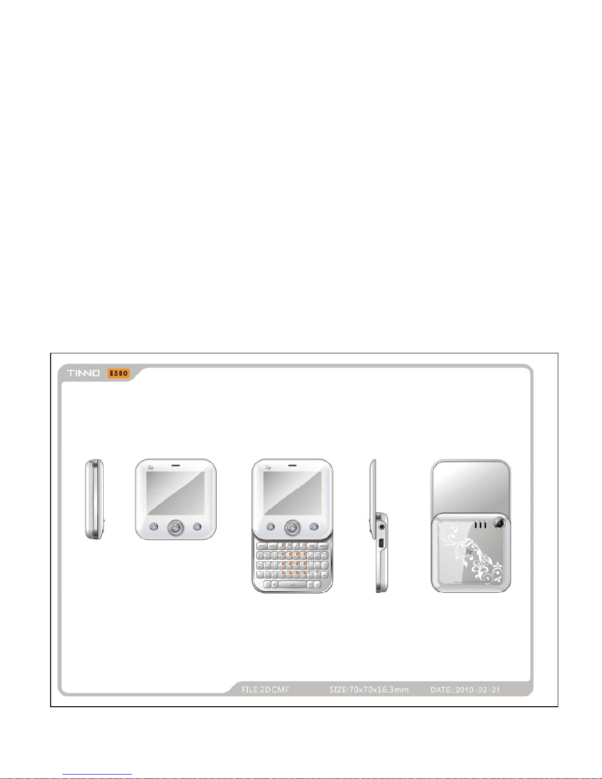
-Slide-Rotating
4. Spec
-SIZE 75X70X15mm
2.4" TFT 26K
Page 2

- 2 -
INTRODUCTION
The purpose of this document is to help service workshop technicians to service products. This service
TABLE OF CONTENTS
INTRODUCTION………………………………………………………………………………..3
Chapter 1 EXPLODED VIEW AND COMPONENT DISPOSAL………………………….4
EXPLODED DIAGRAM………………………………………………………………………….……...4
DISASSEMBL Y AND ASSEMBLY …………………………………………………………….………5
SERVICE TOOLS………………………………………………………………………………...5
DISASSEMBLE…………………………………………………………………………………...7
ASSEMBLY………………………………………………………………………………………..9
Chapter 2 SYSTEM BLOCK DIAGRAM……………………………………………………..11
Chapter 3 INSTRUCTION OF THE UNIT CIRCUIT………………………………………...12
Chapter 4 ACTUALL BOARD…………………………………………………………….….21
SIDE A (MASTER)…………………………………………..……………………………………….….21
SIDE B (SLAVE)……………………………………………………………………………………...….21
Chapter 5 TROUBLESHOOTING……………………………………………………………22
Chapter 6 SOFTWARE INSTRUCTION OF SW UPDATE………………………………..28
SW UPDATE OF MASTER……………………………………………………………..………………32
SW UPDATE OF SLAVE…………………………………………………………………………..……35
Chapter 7 FUNCTION TEST………………………………………………………………….39
Chapter 8 PARAMETER SETTING INSTRUCTION……………………………………….40
Chapter 9 CATCHER INSTRUCTION……………………………………………………….42
Page 3

- 3 -
manual must be used only by authorized service suppliers. The content of it is confidential. Please note that
provides other guidance documents for service suppliers. Follow these regularly and comply with the given
instructions. While every effort has been made to ensure the accuracy of this document, some errors may
exist. Please keep in mind also that this documentation is continuously being updated and modified, so
always watch out for the newest version.
CAUTIONS
Please refer to the phone’s user’s guide for instructions relating to operation, care, and maintenance,
which include important safety information.
1. Servicing and alignment must be undertaken by qualified personnel only.
2. Ensure all work is carried out at an anti-static workstation and that an anti-static wrist strap is worn.
3. Use only approved components as specified in the parts list.
4. Ensure all components, modules, screws, and insulators are correctly re-fitted after servicing and
alignment
5. Ensure all cables and wires are repositioned correctly
Electrostatic discharge can easily damage the sensitive components of electronic products. Therefore,
every service supplier must observe the precautions which mentioned above.
GENERAL REPAIR INFORMATION
1. Make sure your testing equipment is functioning properly before beginning repair work.
2. Before starting repairs you must observe ESD precautions such as being in your ESD
protected area and connecting your wristband.
3. Use gloves to avoid corrosion and fingerprints.
4. Cover windows and displays with a protective film to avoid dust and scratches.
5. Use a lint-free cloth to clean the LCD.
6. When cleaning the pads use a soft cloth\ ESD brush and isopropanol. Do not use a glass
fiber pencil: this scratches the surface and will corrosion.
7. Non-faulty mechanical parts(except shielding lids and bent parts or soldered components).
May be reused if they are not soldered.
8. When removing the shielding lids make sure to replace them with new ones, otherwise the
high-frequency leakage can affect the device.
9. Alw ays use the original spare parts.
10. Check the soldering joints of the parts concerned with regard to the fault symptom. And
resolder them if necessary.
11. Remove excess soldering flux after repair.
12. Observe the torque requirements when assembling the unit.
13. please aware that some malfunctions may be software related and solved by an update
Page 4
- 4 -
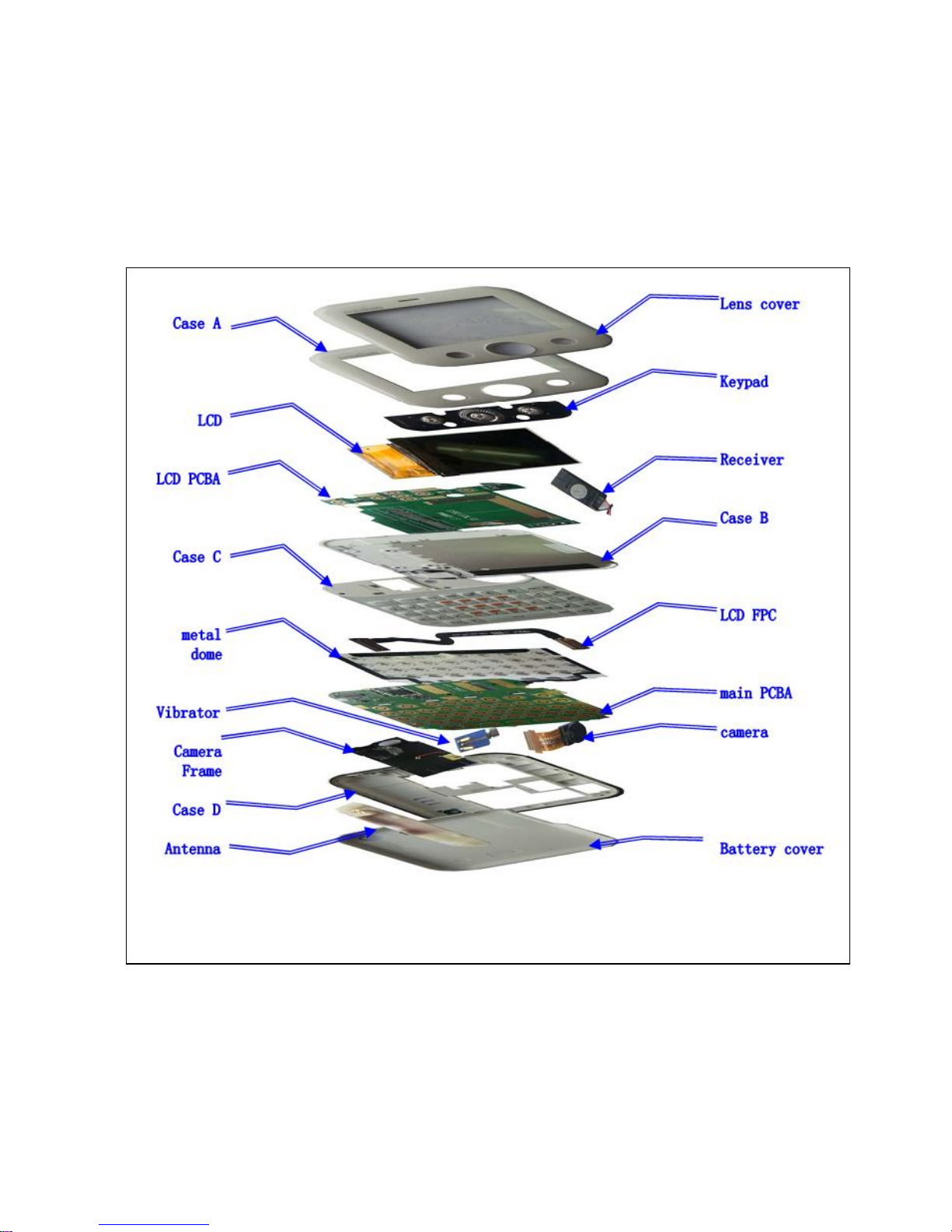
Chapter 1
EXPLODED VIEW AND COMPONENT DISPOSAL
EXPLODED DIAGRAM
Page 5
- 5 -
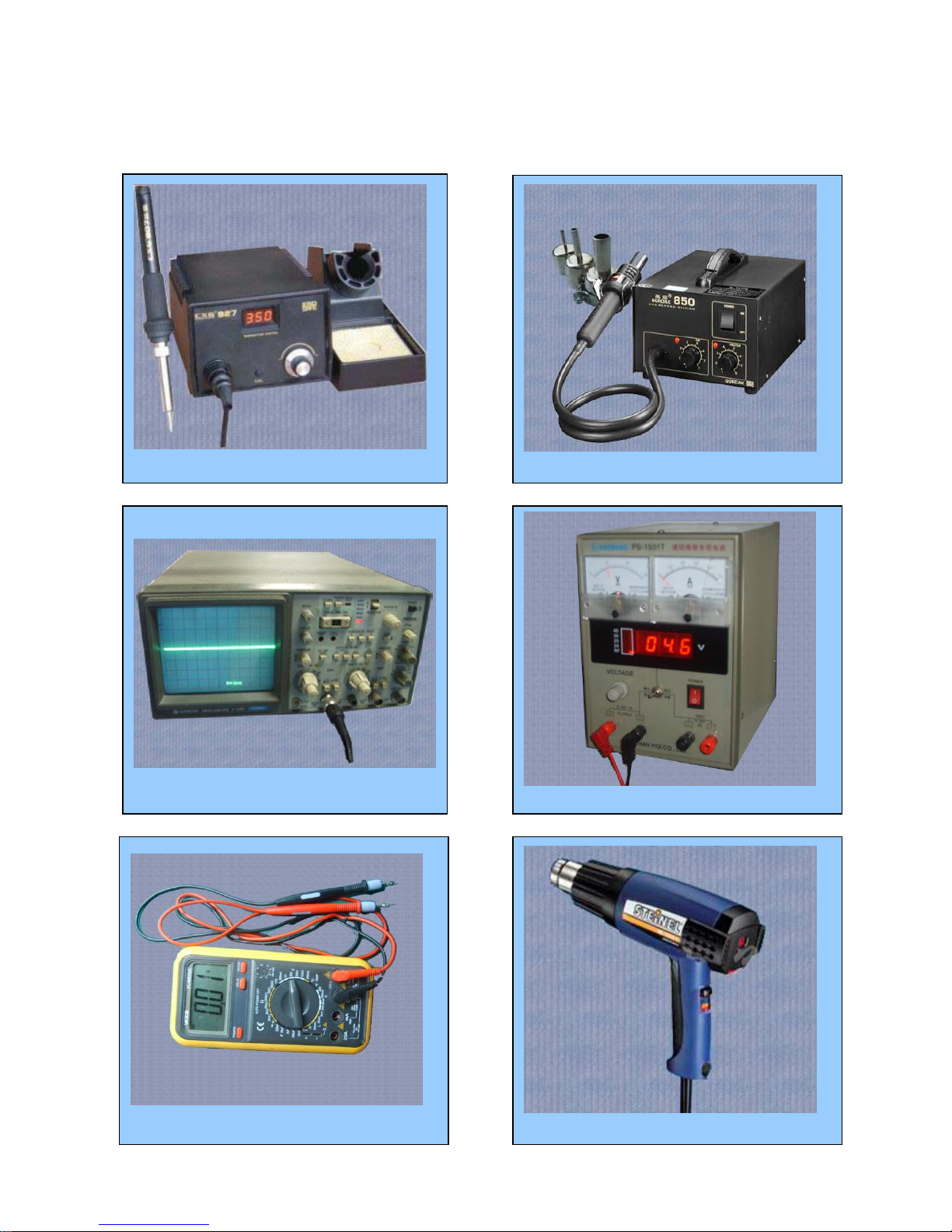
DISASSEMBLY AND ASSEMBLY
SERVICE TOOLS
Voltage regulator
Multimeter
Iron
850 heater
Constant temperature heater
Oscillograph
Page 6
- 6 -
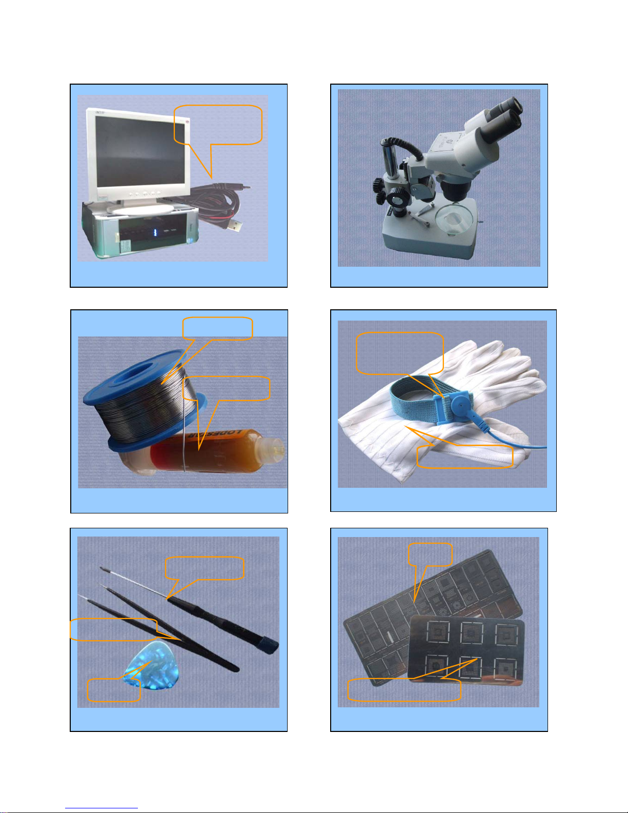
Computer and software download cable
Wrist grounding strap, Antistatic gloves
Wrist
grounding strap
Antistatic gloves
Software
download cable
Microscope
Solder wire, soldering paste
Metal tweezers, Screw driver, SRT-6 Plates
Metal tweezers
SRT-6
Screw driver
MTK series CPU plate
Plate
soldering paste
Solder wire
Page 7
- 7 -
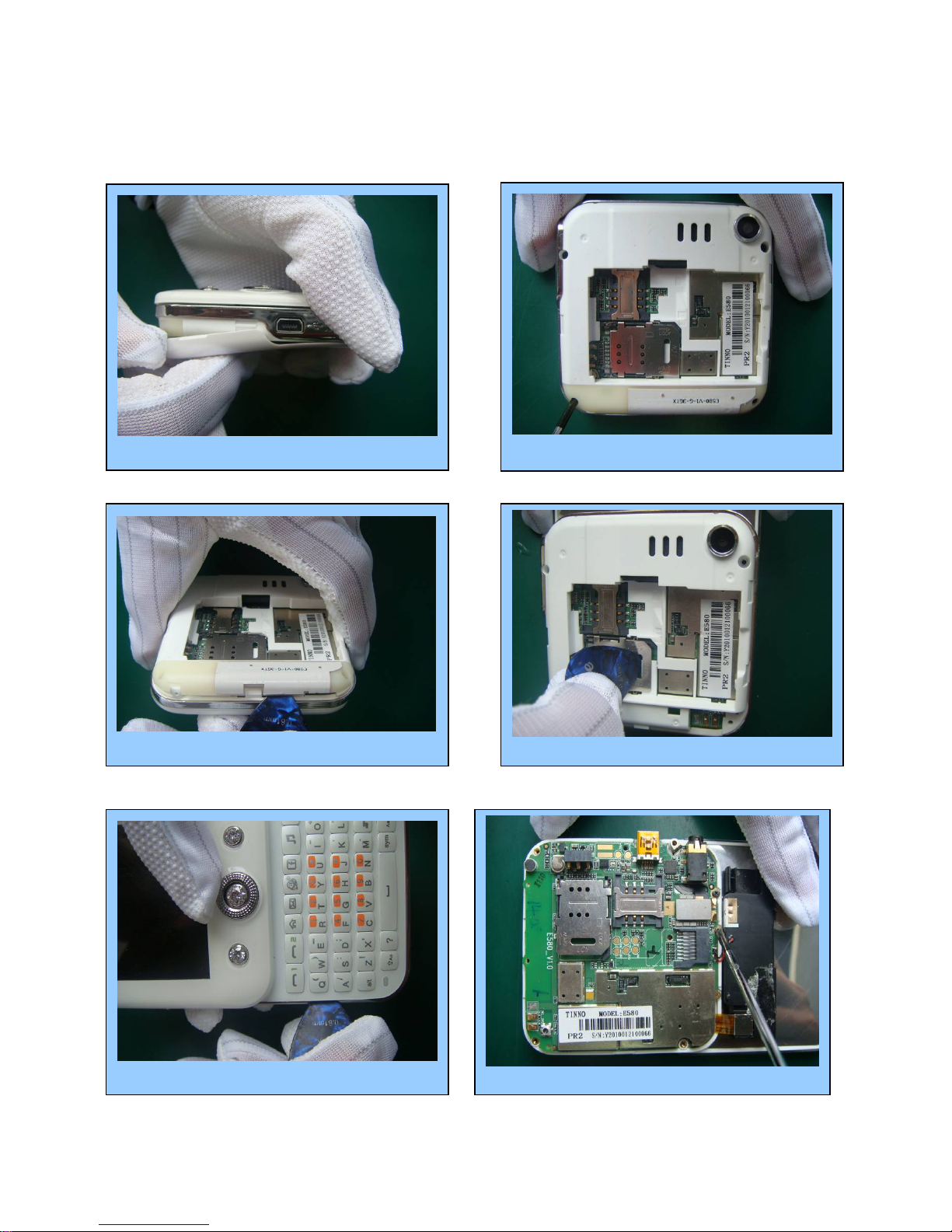
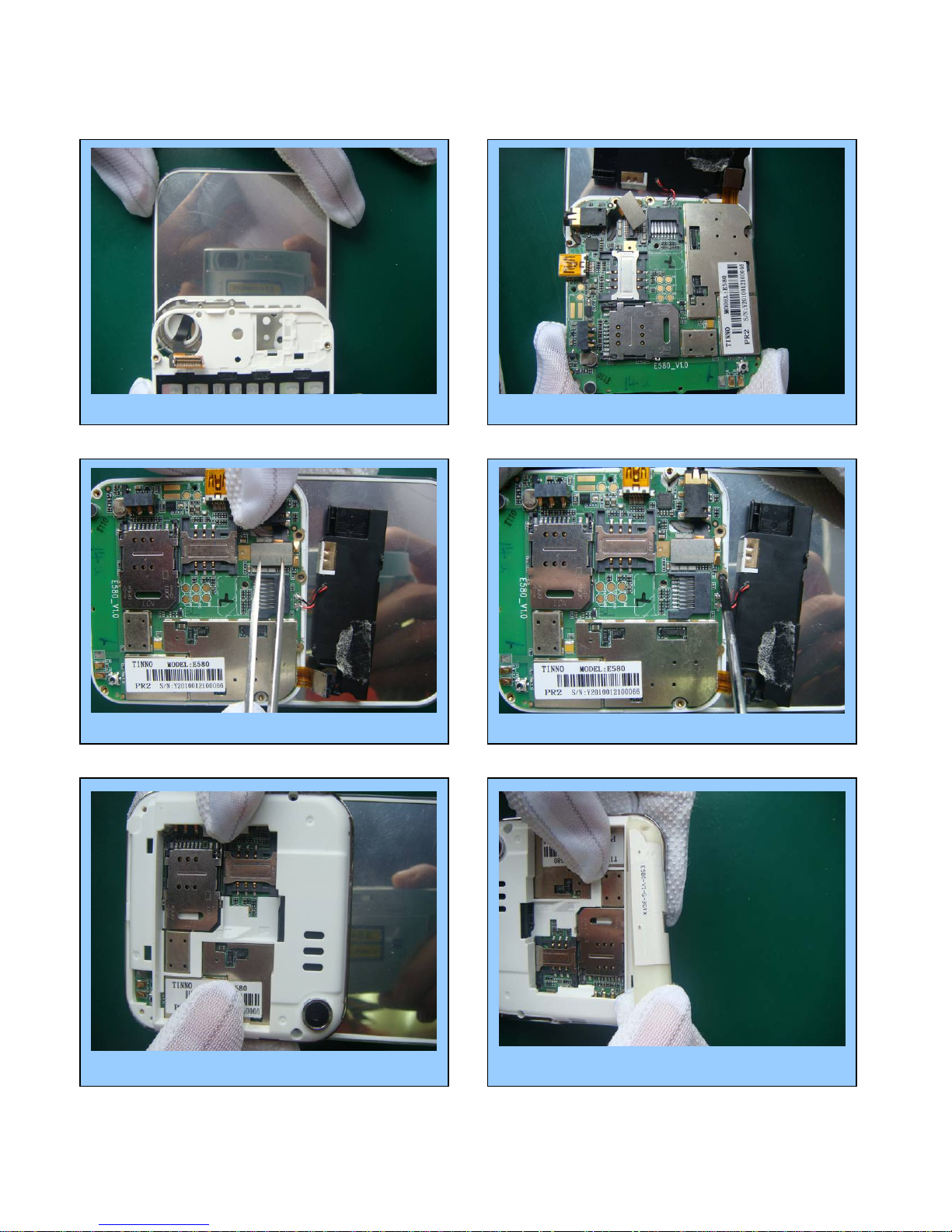
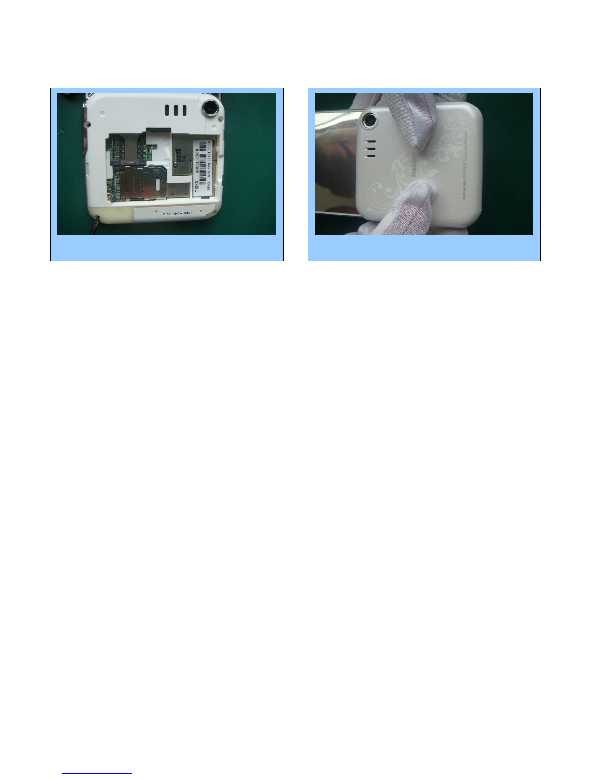
DISASSEMBLY
Take out the battery cover.
Remove 4 screws with screw driver.
Prize up the antenna by pick Prize up SIM buckle
Prize up D cover with pick Remove 2 screws with tweezer
Page 8
- 8 -
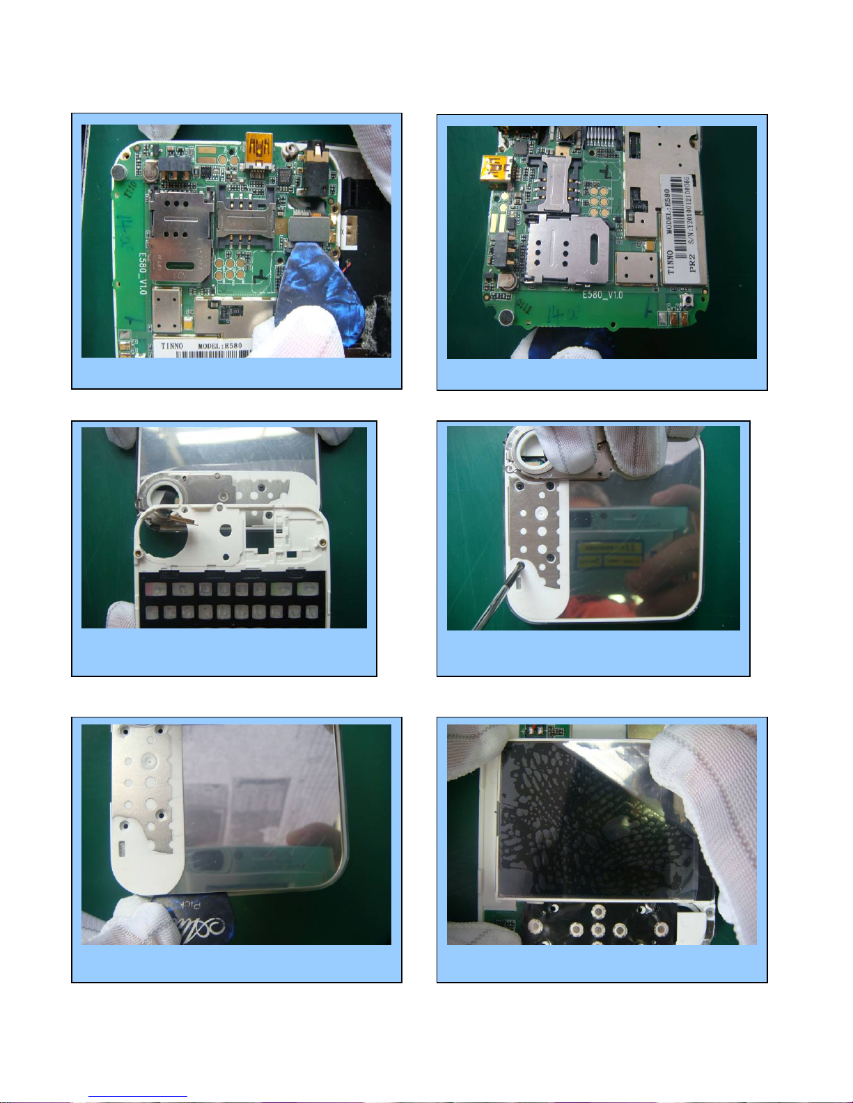
⑺ Take down FPC connector with pick
⑻ Take off PCBA by tweezer
⑼Take out C cover with hands
⑽ Take off 4 screws by tweezer
⑾ Prize up B cover with tweezer ⑿ Stick LCD film
Page 9
- 9 -
Finish
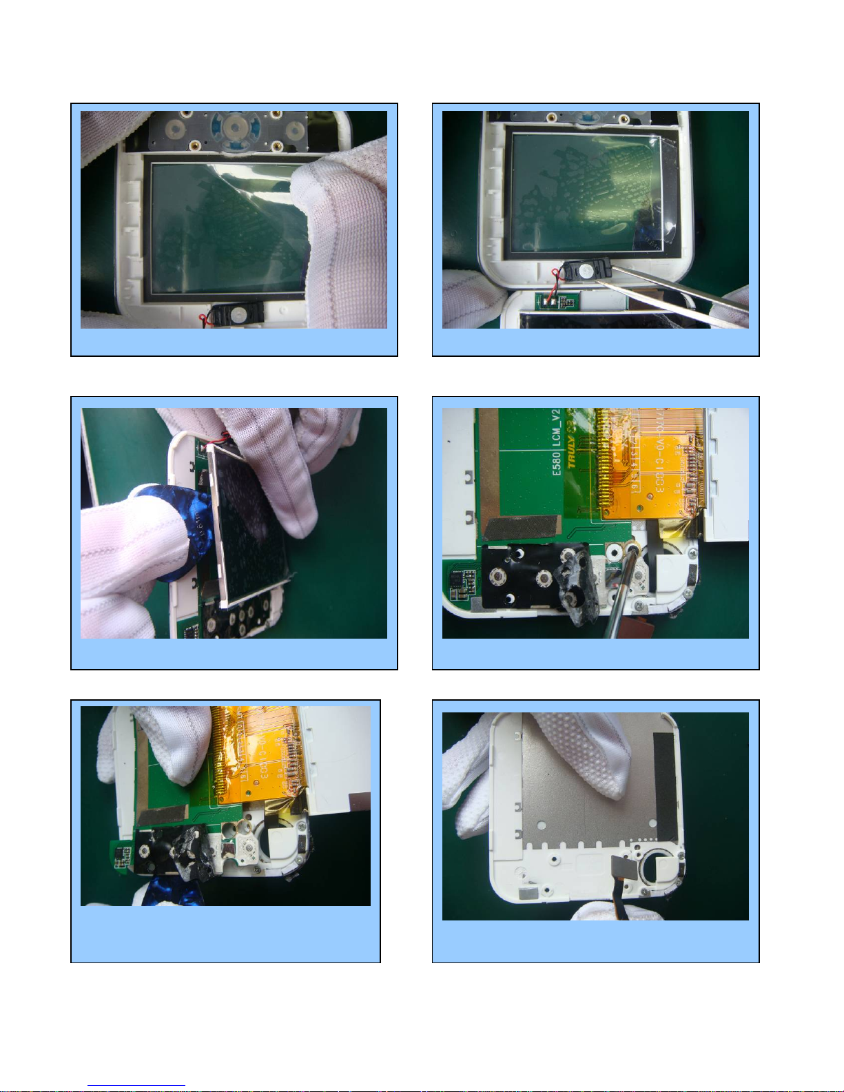
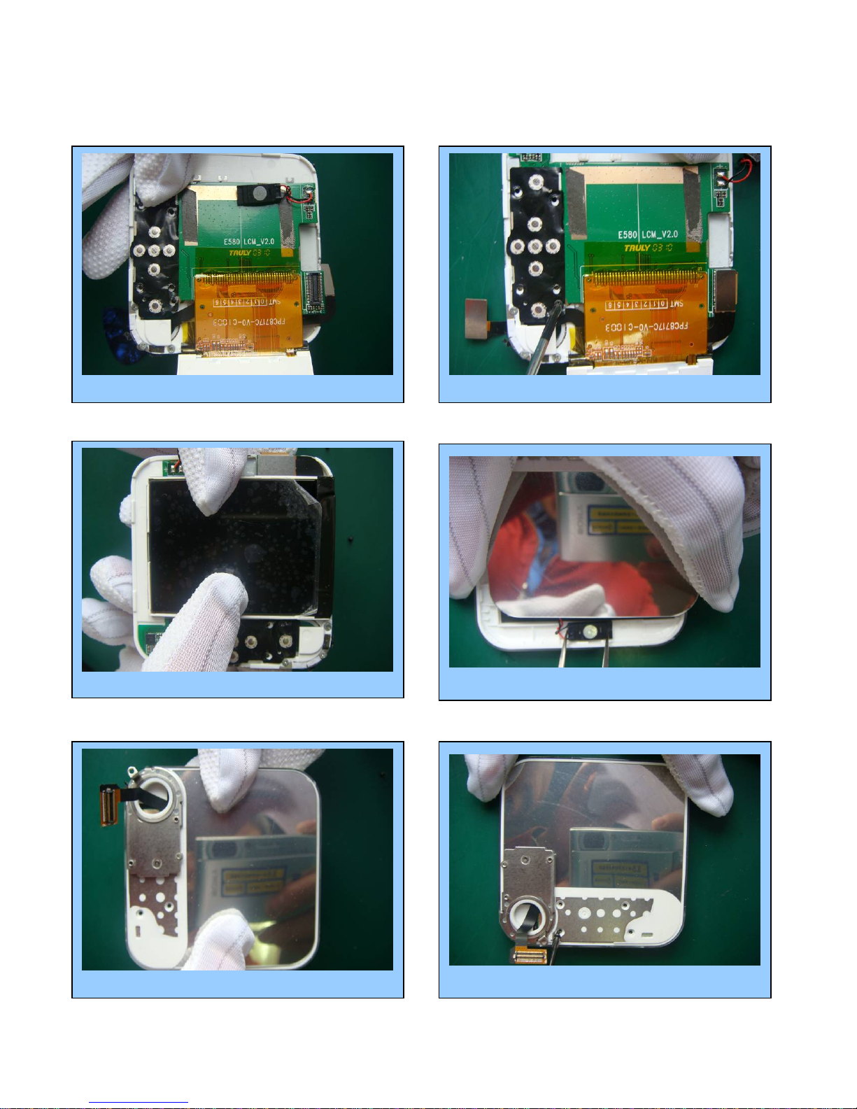
⒀ stick lens protection film ⒁ Take off receiver by tweezer
⒂ Separate LCD with pick
⒄ separate LCD PCBA with tweezer
⒃ Take off the screw with tweezer
⒅ Take off FPC
Page 10
- 10 -
ASSEMBLY
⑴ Place LCD PCBA in A cover ⑵ Lock the screw
⑹ Lock the screws with tweezer ⑸ install B cover
⑷Install receiver with tweezer
⑶ Install LCD
Page 11
- 11 -
⑺ Install cover C
⑿ Install the antenna ⑾Connect FPC with PCBA board
⑽ Lock 3 screws with tweezer
⑻ Place main PCBA in C cover
⑼ Tighten the FPC connector
Page 12
- 12 -
Finish
⒀ Lock 4 screws
⒁ Button the battery cover
Page 13
- 13 -
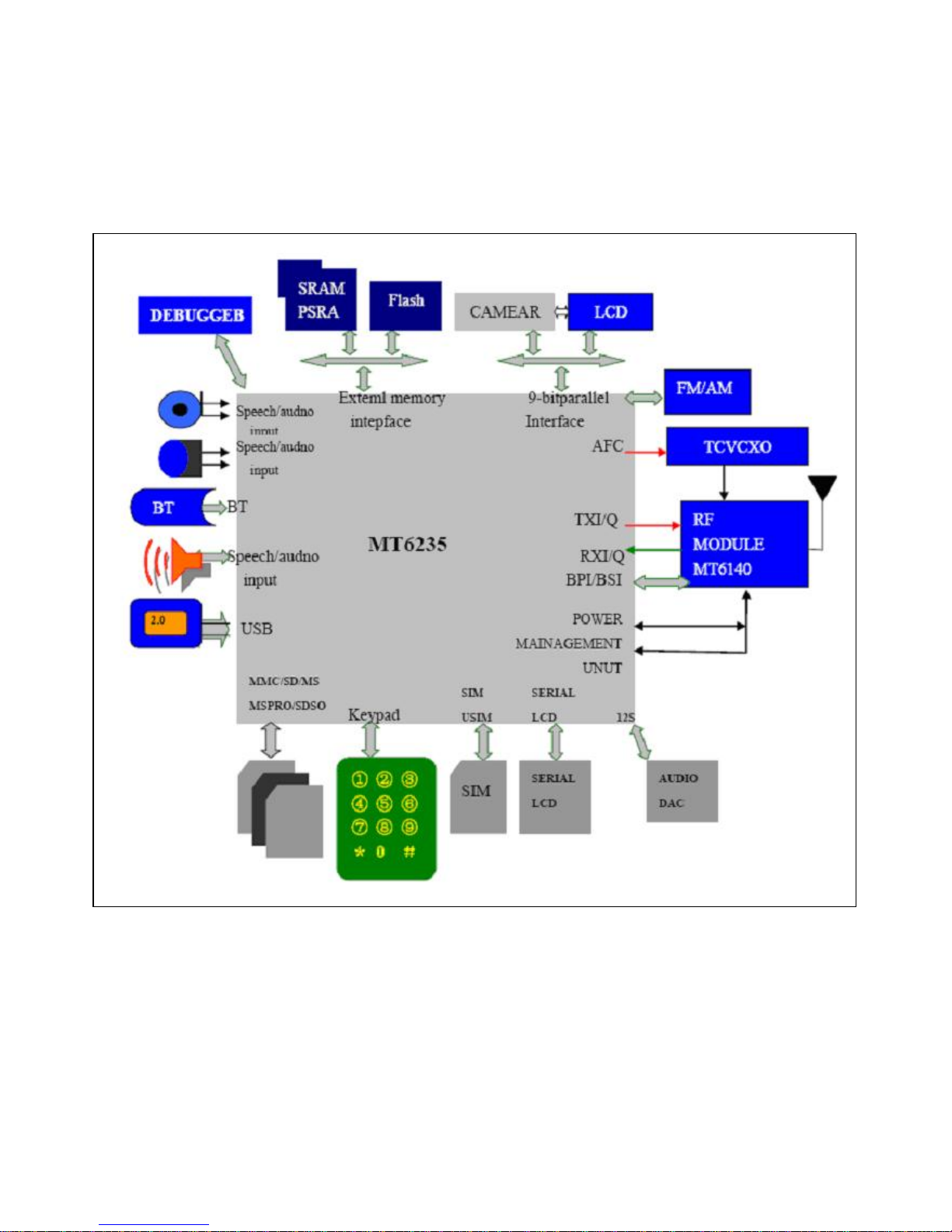
Chapter 2
SYSTEM BLOCK DIAGRAM
CPU (MT6235)
Page 14
- 14 -
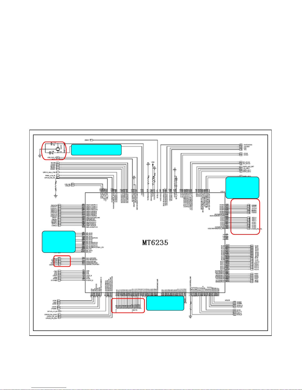
Chapter 3
INSTRUCTION OF THE UNIT CIRCUIT
1. Instruction of the important ICs :
CPU is MT6235 which is the kernel IC of whole main circuit. It also integrates subsystems of channel coder and decoder, cross and
de-cross, encryption and decryption. It takes charge of process of voice and every parts of mobile, such as charge, liberation, LED
etc. And it includes WATCHDOG to improve system stability.
MT6235 is a new generation high-end chip made by MEDIATEK, with a QFN 11.5mm*11.5mm, up to 261pins, 0.47pitch. MT6235
baseband chip has GSM/GPRS capability, also integrates audio and video function. MT6253 provides not only high-quality GPRS
Class 12 MODEM, high-rate data transmission service, but also multi-media applications, like 0.3M pixels camera, mp3, mp4 etc
32k clock signal
BT control
signal
Keypad
signal
Flash signal
MT6235 CPU
Page 15

- 15 -
FM circuit
U204 is FM receiving module. FM_ANT is used to receive the radio signal from the antenna, FM_VCC is the
2.8Vpower supply, FM32KHz is the reference clock, GPIO26 and GPIO31 is control signal from the baseband CPU.
FM ANT
FM output
Page 16

- 16 -
RF circuit
RF part generally means the analog RF and IF process system ,including Antenna system、TX path、RX path、Analog
modem and Frequency Synthesizer .
RF Circuit deals with the RX and TX of wireless signal, with responsibility for the bidirectional transmission of speech and data
between the MS and BS through the air interface. In detail RX part accomplishes the AGC amplifying, mix and demodulation
of RF weak signal received from BS, The final signal output from RX part is the analog baseband I/Q signal. The final RX I/Q
will be sent to Baseband Circuit for later disposal. On the other hand TX part deals with the signal modulation, up-conversion
mix and power amplifying of analog I/Q signal received from baseband, generating burst which meets the GSM specification.
And then the bursts are transmitted to Base station through the antenna. The signal interface between
RF Circuit and Baseband is analog baseband I/Q signal. The performance of RF Circuit can directly affects the signal
transmission quality of the mobile phone.
RF PA adopts RF7161 chip, RF7161 is a high-power dual-mode amplifier module with internal power control.
RPF88150B is used in the stage when GSM / GPRS dual-mode mobile phones amplify transmission array, the working
frequency is from 824MHz to 915MHz and 1710MHz to 1910MHz. There is a input pin to realize the selection of
frequency band. 6mm * 6mm chip package.
Rx path
Tx path
ANT
Page 17

- 17 -
BT circuit
Bluetooth IC processor is MT6612BN/A..
MT6612 is 5mm x 5mm 40-lead (0.5mm pitch) QFN, a high-integrated Bluetooth IC, including rich function and strong
disposal capability, and high performance transceiver.
BT ANT
32MHz clock
Page 18

- 18 -
Chapter4
ACTUALL BOARD
SIDE A
SIDE B
U101 CPU
U301 Flash
J201Battery
connecto
r
n
J302 I/O connector
J702 SIM slot
J501 RF connector
J202 T -flash connector
U501 RF IC
U702 FM IC
U503 antenna switch module
U502 RF PA IC
J303 Earphone
U801 BT IC
Camera
connector
Page 19

- 19 -
Chapter5
TROUBLE SHOOTING
NO
Test flowchart of SIM card
Replace SIM
card
Baseband IC U101may
have fault
Could not read
SIM card
Clean or replace
SIM socket
If points of
SIM are OK
NO NO
NO
YES
YES
YES
YES
OK
End
If SIM card is
invalidation
Connect to steady-voltage
power supply to see
if
Power may be damaged. Test if
voltage of J403 pin4/5 at exactly
power on is 3V. If pin 1/2/3 has
switch of pulse voltage
Replace U101
NO
Page 20

- 20 -
Test flowchart of can not power on (for master)
Replace
battery
May be MT6235 is fault
Could not power
on
Re-solder or replace
J103 of battery
If battery point
of J103 is OK
NO
NO
NO
NO
YES
YES
YES
OK
End
Connect to power
supply, if it can be
p
ower on
If current is 30-40Mx
Update software to
the latest version
Replace/resolder U101
NO
Page 21

- 21 -
The test flowchart of receiver
Replace
receiver
MT6235 defect
No sound in
receiver
Check if LS202 has
sundries or damaged
Handfree
OK?
NO
NO
NO
NO
YES
YES
YES
YES
Repulse LS202 or
clean it
If receiver is connect
OK or not
Remove receiver and test it by
multimeter’s beep function. If there is
sound like ‘sasa’ from receive
r
Replace
receiver
Replace U101
NO
NO
NO
Page 22

- 22 -
Test flowchart of incoming call with no ring.
Cancel
libration /mute
mode
Can test output sound signal
at B203/B204 by a
oscillograph when bell works
No sound of bell
Remove headphone
and test it by
multimeter’s beep
function. If there is
sound like ‘sasa’ from
headphone
NO
NO
NO
YES
YES
YES
YES
Replace bell
components
If it is libration /
mute mode.
If volume level
is lowest
Turn up the volume
Replace MT6235
NO
Use *#84666*# No.
7 to hear if bell has
sound
NO
Page 23

- 23 -
Test flowchart of no display or display abnormally.
Clean and
re-solder J603
Update software to
the latest version
No display or
display abnormal
Replace LCD
NO
NO
NO
OK
YES
YES
If display interface
connects OK
Replace LCD
End
Replace or re-solder
MT6235
Check LCD broken or
n
ot o
r leak
NO
OK
Page 24

- 24 -
Test flowchart of download failed
Replace or
re-solder J103
connector
Check if power management and LD0
have output voltage normally and
whether there is broken of
p
ower suppl
y
Can not download
Check conditions outside
the mobile, such as
configuration of software,
cable, power, PC etc.
If mobile is
power on
NO
NO
NO
NO
YES
YES
YES
YES
YES
OK
Replace or re-configure
Check if J103 connector
is false solder or
damaged
Connect download cable. Check
whether current is larger than
normal. (Normally is about 30mA)
Disconnect cable
immediately and touch
chip gently to check if
the chip is heat
Test VCORE, VDD, VADD,
VTCXO, VRTC, VMEM and clock
signal o
f 26MHZ
、
3
2KHZ.
Replace MT6235
NO
NO
Page 25

- 25 -
Chapter6
Instruction of SW update
1. Install the USB driver without the USB cable plugged into the computer.
2. After it is ok, plug the cable then check the device manager as the picture below:
Page 26

- 26 -
4. Select Format FAT (DISABLED).
3. Open SW updating platform FlashTool_v3.0848.00
Double click the icon FlashTool. Choose the port which the cable be connected to the
computer.
Page 27

- 27 -
5. Choose “Auto Format FAT”, and don’t select “Validation”.
6. Click “Download Agent” to transfer “MTK_AllInOne_DA.bin” file.
Double click
Page 28

- 28 -
7. Update with the update cable. (The actually file name please refer to your software)
(1) As showed bellow, click “Scatter-loading” to transfer “****.txt” file in the folder of the new software.
Double click
Double click
Page 29

- 29 -
(2) Here, ROM/Boot files can be selected automatically. Don’t need to choose.
(3) Making sure the phone is powered off and the battery is taken out. Click “download”, then link the cable for the
master to the phone, insert the battery and keep pressing the power-on button for a while, soon the red progressing
bar will occur. Blue progressing bar appears after the blue one. Then an icon occurs to show the finish of
downloading.
Page 30

- 30 -
(4) As showed the phone is checked.
(5) As showed the software is written in.
Page 31

- 31 -
(6) This icon shows the finish of the downloading.
Page 32

- 32 -
Chapter7
FUNCTION TEST
Press “#84666*#” to check these items in stand by mode:
1. Version: to check the version of the software
2. Echo Loop: blow to the mic, the receiver will have a sound
3. Key: press relevant keys appear in the screen
5. Libration: The cellphone will librate
6. Lond SPK: there will be a sound from the speaker
7. Ring: press start there will be some music from the speaker
8. LED: press confirm button to check if LED is normal
9. LCD: LCD will Auto Display
11. Receiver: there will be a sound from the receiver
Camera ->Menu -> Camera-> to test if the camera is available or not
Page 33

- 33 -
Chapter8
PARAMETER SETTING INSTRUCTION
China mobile as an example, other countries please inquire the local operator
1. WAP parameter setting instruction
1) Data Account Process: Menu→Services→Data Account
GSM Data: Account Name: (default)
Number: 17266
User Name: WAP
Password: WAP
Line Type: ISDN
Speed: 9.6 Kbps
DNS: 010.000.000.172
GPRS: Account Name: (default)
APN: cnwap
User Name: WAP
Password: WAP
Auth. Type: (default)
2) WAP setting process: Menu→Services→WAP→Settings→Edit Profile
Edit Profile: Rename Profile: Optional
Homepage: http://monternet.com
Data Account: GSM/GPRS
Connection Type: HTTP (Proxy Address: 010.000.000.172)
Username: Optional
Password: Optional
After setting as above, the WAP is ready.
2. MMS parameter setting instruction (Premise is WAP is valid)
Setting process: Menu→Messages→MMS→Message Settings→Server Profile→Edit profile
Edit Profile: Rename Profile: Same as WAP Profile name
Homepage: http://mmsc.monternet.com
Data Account: Same as WAP Data Account
Connection Type: Same as WAP Data Account
Username: Optional
Password: Optional
After setting as above, the MMS is ready.
3. Email parameter setting instruction (Premise is WAP is valid)
1) GPRS setting process: Menu→Services→Data Account→GPRS
Edit Profile: Account Name: Optional
APN: cmnet
2) Email Profile setting process: Menu→Messages→Email→Email Profile
A. Outgoing server: stmp.126.com (depend on the user’s Email website )
Page 34

- 34 -
E-Mail Address: Full E-Mail Address of the user’s
Password: Password of the use’s E-Mail
B. Incoming server: pop3.126.com (depend on the user’s Email website )
E-Mail Address: Full E-Mail Address of the user’s
Password: Password of the use’s E-Mail
After setting as above, the MMS is ready.
Page 35

- 35 -
Chapter9
CATCHER INSTRUCTION
General: The figures in this document help to understanding, and they may not be exactly the same as
showed in your computer. Contact us please when you have any queries.
1 Install the USB driver if not yet.
1.1 Run the USB driver without the upgrade cable plugged into the computer.
Figure 1
1.2 After the installation is completed, plug the upgrade cable into the computer’s USB connector, and then check
the device manager as in figure 2:
Figure 2
Page 36

- 36 -
2 set the phone to prepare for using Catcher.
Open the phone and input “*#84666364*#” to enter the setting screen. In sequence enter DEVICE, UART, and
TST config. Choose UART1 and Clink done, and then the phone restarts. After the phone restarts, power it off.
3 choose the Database of the phone’s software.
3.1 run “Catcher.exe”, choose Config →.Set Database Path. The figures (figure 3, figure 4, and figure 5) occur in
sequence as below.
Figure 3
Figure 4
Page 37

- 37 -
Figure 5
3.2 Clink the button “...” in figure 5 to choose the Database file of the master phone or slave phone (for example
“BPLGUInfoCustomSrcP_MT6226M_S01_X6+_FLP_06_12_V3_2-TN-MP-5B-QN” file ). Refer to figure 6
showed as below:
Figure 6
When you examine the master phone’s problems, choose the master phone software’s database file, and when
the slave phone’s problems, the slave phone’s database file.
The database in the phone must be exactly the same as the chose database for Catcher, or the figure 14 will
occur when the Catcher work.
4 enter Logging mode and choose the right COM
4.1 clink the “Logging code” button in the red note in figure 7. Then figure 8 occurs.
Figure 7
Page 38

- 38 -
Figure 8
4.2 clink button “Configure RS232” in figure 9, then figure 10 occurs, choose the right COM in Port option, and
clink OK.
Figure 9
Page 39

- 39 -
Figure 10
5 use the Catcher to record debug information
5.1 clink the button “connect” in figure 11, clink the button “Default Filter” in figure12, select “Field Trial” button in
figure 13, and then clink “set” in Figure13.
Figure 11
Page 40

- 40 -
Figure 12
Figure 13
5.2 Clink “Filter” in figure 14, choose some items in figure 15, and then clink ok in figure 15. (Please query us if
you need to choose the filter settings)
Page 41

- 41 -
Figure 14
Figure 15
5.2 connect the upgrade cable to the phone and power on the phone. If the database in the phone is not exactly
the same as the chose database in Catcher, figure 16 occurs (for example, different software versions and wrong
cable connectors lead to the difference between the databases). You have to clink “EXIT” and make the
databases the same.
Page 42

- 42 -
Figure 16
5.3 The catcher records primitive information as showed in figure 17. Clink the button “clear” in figure 18 to clear
the useful primitive information. Then the phone user carries on some operations to the phone to make the
failures recur. After the wanted failures occur wholly, clink the button “disconnect” in figure 19. You can save the
“.clg” file now as showed in figure 20, and name it. The “.clg” file is that needed for analyzing the failures of
phone.
Figure 17
Page 43

- 43 -
Figure 18
Figure 19
Page 44

- 44 -
Figure 20
Page 45

 Loading...