

Page 1
EN – English
Instruction manual
VA 525
Compact inline flow sensor with
integrated flow straightener
VA 525 EN V1.01 Page 1 of 41
Page 2

Foreword
I. Foreword
Dear customer,
thank you very much for deciding in favour of the VA 525. Please read this
installation and operation manual carefully before mounting and initiating the device
and follow our advice. A riskless operation and a correct functioning of the
VA 525 are only guaranteed in case of careful observation of the described
instructions and notes
Sales Office South / Geschäftsstelle Süd
Zindelsteiner Str. 15
D-78052 VS-Tannheim
Tel.: +49 (0) 7705 978 99 0
Fax: +49 (0) 7705 978 99 20
Mail: info@cs-instruments.com
Web: http://www.cs-instruments.com
Sales Office North / Geschäftsstelle Nord
Am Oxer 28c
D-24955 Harrislee
Tel.: +49 (0) 461 700 20 25
Fax: +49 (0) 461 700 20 26
Mail: info@cs-instruments.com
Web: http://www.cs-instruments.com
VA 525 EN V1.01 page 2 o 41
Page 3

Table of Content
II. Table of Contents
I. Foreword ....................................................................................................................... 2
II. Table of Contents ...................................................................................................... 3
1 Intended use .................................................................................................................. 5
2 Safety instructions ........................................................................................................ 5
3 Instruments description ............................................................................................... 6
4 Technical data ............................................................................................................... 7
5 Scaling Analogue output Comprssed Air ................................................................. 8
6 Installation Description ................................................................................................ 9
6.1 Installation of VA 525 ............................................................................................................ 9
7 Flow measuring ranges ...............................................................................................10
7.1 Flow for different gases....................................................................................................... 10
8 Dimensions ..................................................................................................................11
9 Electrical wiring ...........................................................................................................12
9.1 Modbus RTU, 4…20mA, Pulse, MBus or Ethernet ............................................................ 12
9.2 Connection diagrams .......................................................................................................... 13
9.2.1 Modbus ............................................................................................................................ 13
9.2.2 4..20mA / Impuls .............................................................................................................. 13
9.2.3 MBus ................................................................................................................................ 13
9.2.4 Ethernet (optional PoE) .................................................................................................. 14
VA 525 EN V1.01 Page 3 of 41
Page 4

Table of Content
10 Operation...................................................................................................................15
10.1 Initialization .......................................................................................................................... 16
10.2 Main menu after switching on ............................................................................................ 16
10.3 Settings ................................................................................................................................. 17
10.3.1 Settings Setup.................................................................................................................. 18
10.3.1.1 Input / change tube diameter .................................................................................... 18
10.3.1.2 Input / change consumption counter ........................................................................ 19
10.3.1.3 Definition of the units for flow, velocity, temperature and pressure ......................... 19
10.3.1.4 Advanced settings .................................................................................................... 20
10.3.1.4.1 Definition of the reference conditions ................................................................... 20
10.3.1.4.2 Time setting for filtering ........................................................................................ 22
10.3.1.5 Setting of Zeropoint and Low-flow cut off ................................................................. 23
10.3.1.6 Pressur settings ........................................................................................................ 24
10.3.2 Modbus settings ............................................................................................................... 25
10.3.2.1 Modbus RTU Setup .................................................................................................. 25
10.3.3 Ethernet (Modbus TCP) ................................................................................................... 26
10.3.3.1.1 Network Setup DHCP ........................................................................................... 26
10.3.3.2 Network Settings static IP ......................................................................................... 27
10.3.3.3 Modbus TCP Settings ............................................................................................... 28
10.3.3.4 Modbus Settings (2001…2005) ............................................................................. 29
10.3.3.5 Values Register (1001 …1500) ................................................................................ 29
10.3.4 Pulse /Alarm ..................................................................................................................... 31
10.3.4.1 Pulse output .............................................................................................................. 31
10.3.5 User Setup ....................................................................................................................... 32
10.3.5.1 Password .................................................................................................................. 32
10.3.5.2 Language .................................................................................................................. 32
10.3.5.3 Display / Touch ......................................................................................................... 33
10.3.6 Advanced ......................................................................................................................... 33
10.3.7 4 -20mA ........................................................................................................................... 34
10.3.8 VA 525 Info ...................................................................................................................... 36
10.4 MBus...................................................................................................................................... 37
10.4.1 Default Settings communication ...................................................................................... 37
10.4.2 Default values transmitted ............................................................................................... 37
11 Status / Error messages ...........................................................................................38
11.1 Status messages .................................................................................................................. 38
11.2 Error messages .................................................................................................................... 39
12 Maintenance ..............................................................................................................40
13 Cleaning of the sensor head ....................................................................................40
14 Re-Calibration ...........................................................................................................40
15 Spare parts and repair ..............................................................................................40
16 Calibration .................................................................................................................40
17 Warranty ....................................................................................................................40
VA 525 EN V1.01 page 4 o 41
Page 5

Instruments decription
1 Intended use
The VA 525 consumption sensor is used for continuous flow measurements.
The VA 525 consumption sensor is designed and constructed exclusively for the intended purpose
described here and may only be used accordingly.
The user must check whether the instrument is suitable for the selected application. It must be
ensured that the medium is compatible with the wetted parts. The technical data listed in the data
sheet are binding.
Improper handling or operation outside the technical specifications is not permitted. Claims of any
kind based on improper use are excluded.
Operating principle:
The VA 525 consumption probe operates according to the calorimetric measuring method.
The basis of this measuring method is the electrical heating of the mechanically protected built-in
sensor. The mass flow, the volume flow and the flow velocity can be measured and determined by
the resulting heat flow to the passing medium (gas).
With the calorimetric measurement method (based on the measurement principle), the operating
temperature and pressure of the medium have no influence on the measurement result, only the
material data of the gas component are decisive.
2 Safety instructions
Please read carefully before starting the device!
Warning: Do not exceed the pressure range of 16 bar!
Observe the measuring range of the sensor!
Always observe the direction of flow when positioning the sensor!
The screwed fixture must be pressure tight.
It is absolutely necessary to avoid condensation on the sensor element or water drops in the
measuring air as they may cause faulty measuring results.
The manufacturer cannot be held liable for any damage which occurs as a result of non-
observance or non-compliance with these instructions. Should the device be tampered with
in any manner other than a procedure which is described and specified in the manual, the
warranty is cancelled and the manufacturer is exempt from liability.
The device is destined exclusively for the described application.
We offer no guarantee for the suitability for any other purpose and are not liable for errors
which may have slipped into this operation manual. We are also not liable for consequential
damage resulting from the delivery, capability or use of this device.
We offer you to take back the instruments of the instruments family VA 525 which you would
like to dispose of.
Qualified employees from the measurement and control technology branch should only carry
out adjustments and calibrations.
VA 525 EN V1.01 Page 5 of 41
Page 6

Instruments decription
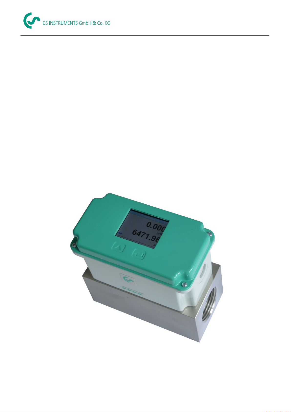
3 Instruments description
The newly developed VA 525 combines modern digital interfaces for connection to energy
monitoring systems with a small, compact design. The VA 525 is always used when many
machines (compressed air consumers) are to be connected/integrated to a energy
monitoring network.
Special features:
Compact, small design - for use in machines, behind the maintenance unit on the
final consumers
Screw-in thread for easy installation in existing pipelines due to integrated measuring
block
- Sizes : ¼", ½" ¾", 1" 1 ¼" , 1 ½" and 2"
Integrated flow straighteners (no inlet runs necessary)
Integrated display with presentation of 2 values
- Flow & Consumption,
- Speed & Temperature
Operation via integrated keyboard
- Units selection
freely selectable. m³/h, m³/min, l/min, l/s, kg/h, kg/min, g/s, lb/min, lb/h
Cfm, m/s,ft/min
Digital interfaces
- Modbus RTU (RS485)
- Ethernet
- MBus
Analog interfaces
- 4..20mA
- Pulse output galv. insulated.
Pressure measurement (optional)
Noze The optional CS Instruments Service Software enables you to:
Selection/conversion of gas type (air, nitrogen, argon, nitrous oxide, CO2, oxygen)
Calibration Analog output 4..20mA
Read out service data
sensor diagnosis
VA 525 EN V1.01 Page 6 of 41
Page 7

Technische Daten
4 Technical data
Measurement: Flow and consumption
Reference Standard: Standard settings ex works:
DIN 1945, ISO 1217 at 20°C and 1000 mbar
Selectable Units m³/h (Standard settings ex works)
m³/h, m³/min, l/min, l/s, kg/h, kg/min, g/s, lb/min, lb/h Cfm,
m/s,ft/min
Measuring principle: calorimetric measurement
Sensor: Pt45, Pt1000
Measuring medium: Air, gases
Operating temperature: -30 ... 80°C probe tube
-20 ... 70°C housing
Operating pressure: up to 16 bar,
Power supply: 18 to 36 VDC
Power consumption: max. 5W
Digital output: RS 485 (Modbus RTU)
MBus (optinal)
Ethernet oder Ethernet-PoE (optional)
Analog output: 4...20 mA (see chapter 4), max. burden < 500 Ohm
Pulse output: pulse output potential free (dry contact)
passive: max. 48Vdc, 150mA
1 pulse pro m³ resp. pro l,
Valency adjustable with the display keys
Accuracy: ± 1,5 % m.v., ± 0,3 % f. s.*
Display: TFT 1.8 Resolution 220 x 176 (optinal)
Mounting thread: G ¼”,, G ½”, G ¾”, G1", G 1¼” G 1½”, G 2”
measuring block
Material measuring block: Aluminium
Protection calss: IP65
* m.v. = measured values
f.s. = full scale
VA 525 EN V1.01 Page 7 of 41
Page 8

Scaling Analogue output
Description
Version
Analogue output
VA 525 with integrated ¼” measuring block
Low Speed
4… 20 mA =
0...25 l/min
Standard
0...50 l/min
Max
0...105 l/min
High Speed
0...130 l/min
VA 525 with integrated ½” measuring block
Low Speed
4… 20 mA =
0...20 m³/h
Standard
0...45 m³/h
Max
0...90 m³/h
High Speed
0...110 m³/h
VA 525 with integrated ¾” measuring block
Low Speed
4… 20 mA =
0...45 m³/h
Standard
0...85 m³/h
Max
0...175 m³/h
High Speed
0...215 m³/h
VA 525 with integrated 1" measuring block
Low Speed
4… 20 mA =
0...75 m³/h
Standard
0...145 m³/h
Max
0...290 m³/h
High Speed
0...355 m³/h
VA 525 with integrated 1¼” measuring block
Low Speed
4… 20 mA =
0...140 m³/h
Standard
0...265 m³/h
Max
0...530 m³/h
High Speed
0...640 m³/h
VA 525 with integrated 1½” measuring block
Low Speed
4… 20 mA =
0...195 m³/h
Standard
0...365 m³/h
Max
0...730 m³/h
High Speed
0...885 m³/h
VA 525 with integrated 2" measuring block
Low Speed
4… 20 mA =
0...320 m³/h
Standard
0...600 m³/h
Max
0…1195m³/h
High Speed
0...1450 m³/h
5 Scaling Analogue output Comprssed Air
Reference DIN1945/ ISO 1217: 20°C, 1000 mbar (Reference during calibration)
VA 525 EN V1.01 Page 8 of 41
Page 9

6 Installation Description
An installation at customer site is only allowed in the unpressurized state of the system.
Tightness of the connection must be checked and ensured.
6.1 Installation of VA 525
The sensor VA 525 is pre-supplied with the measuring block.
Measuring ranges
VA 525 EN V1.01 Page 9 of 41
Page 10
1/4"
1/2"
3/4"
1"
1 ¼"
1 ½"
2"
Analog
output
20mA
Analog
output
20mA
Analog
output
20mA
Analog
output
20mA
Analog
output
20mA
Analog
output
20mA
Analog
output
20mA
l/min
[m³/h]
[m³/h]
[m³/h]
[m³/h]
[m³/h]
[m³/h]
Reference DIN1945/ ISO 1217: 20°C, 1000 mbar (Reference during calibration)
Air
Low Speed
25
20
45
75
140
195
320
Standard
50
45
85
145
265
365
600
Max
105
90
175
290
530
730
1195
High Speed
130
110
215
355
640
885
1450
Adjustment to DIN 1343: 0°C, 1013,25 mbar
Air
Low Speed
25
20
40
70
130
180
295
Standard
50
40
80
135
240
335
550
Max
100
80
160
270
485
670
1100
High Speed
120
100
195
325
590
815
1330
Argon
(Ar)
Low Speed
45
35
75
120
220
305
505
Standard
85
70
135
230
415
570
935
Max
170
140
275
460
830
1140
1870
High Speed
205
170
335
555
1005
1385
2265
Carbon dioxide
(CO2)
Low Speed
25
20
45
75
140
195
320
Standard
50
45
85
145
260
360
590
Max
105
90
175
290
525
720
1185
High Speed
130
105
210
350
635
875
1430
Nitrogen
(N2)
Low Speed
25
20
40
70
130
180
295
Standard
50
40
80
135
240
335
550
Max
100
80
160
270
485
670
1100
High Speed
120
100
195
325
590
815
1330
Oxygen f
(O2)
Low Speed
25
20
45
75
135
185
305
Standard
50
40
80
140
250
345
570
Max
100
85
165
280
505
695
1140
High Speed
125
105
205
340
610
845
1380
Nitrous oxide
(N2O)
Low Speed
Standard
50
40
85
140
260
355
585
Max
105
85
170
285
520
715
1170
High Speed
125
105
210
345
630
865
1420
7 Flow measuring ranges
7.1 Flow for different gases
Measuring ranges
Other gases on request
Please note:
The area outside the pipeline (ambient area of the sensor) must not be an explosive area.
VA 525 EN V1.01 Page 10 of 41
Page 11
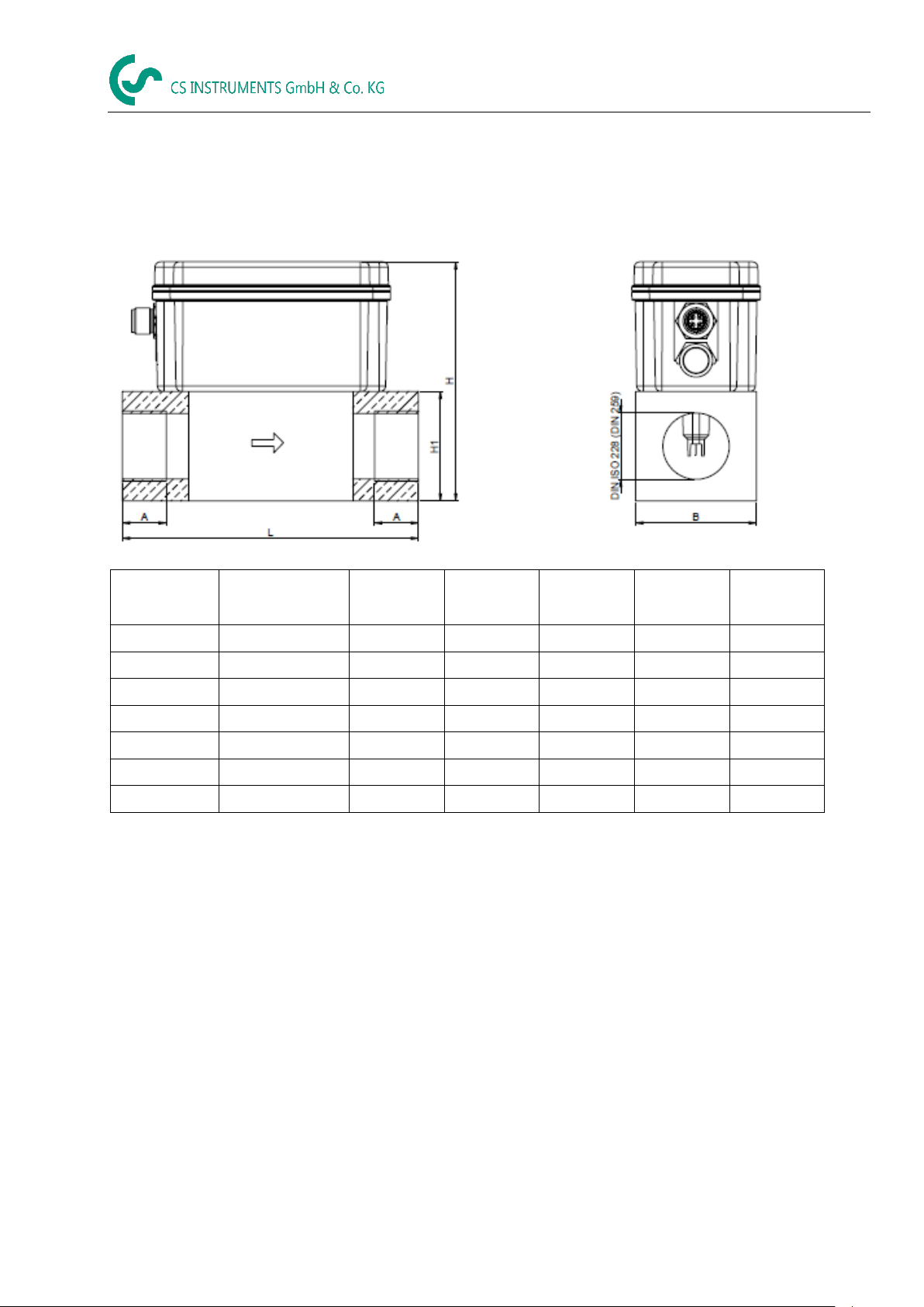
8 Dimensions
Nominal
width
Connection
thread
L
[mm]
B
[mm]
H1
[mm]
H
[mm]
A
[mm]
DN 8
G 1/4"
135
55
50
109,1
15
DN 15
G 1/2"
135
55
50
109,1
20
DN 20
G 3/4"
135
55
50
109,1
20
DN 25
G 1"
135
55
50
109,1
25
DN 32
G1 1/4"
135
80
80
139,1
25
DN 40
G1 1/2"
135
80
80
139,1
25
DN 50
G 2"
135
80
80
139,1
30
Dimensions
VA 525 EN V1.01 Page 11 of 41
Page 12

Electrical wiring
Pin 1
Pin 2
Pin 3
Pin 4
Pin 5
Connector plug A
Version Modbus
+VB
RS 485 (A)
-VB
RS 485 (B)
NC
Connector plug A
(Version 4..20mA)
+VB
Pulse
galv. isolated
-VB
Pulse
galv. isolated
I+
4..20 mA
Connector plug A
Version MBus
+VB
NC
-VB
MBus
MBus
Colours cables
0553 0106 (5 m)
0553.0107 (10 m)
brown
white
blue
black
grey
-VB
Negative supply voltage 0 V
Pulse
Pulse for consumption
+VB
Positive supply voltage 18...36 VDC
smoothed
NC
Must not be connected to a voltage
and/or to protection earth. Please cut
and isolate cables.
I +
Current signal 4...20 mA
(selected measured signal)
RS 485 (A)
RS 485 (B)
Modbus RTU A
Modbus RTU B
MBus
MBus (reverse polarity protected)
If no connection cable cable is
ordered the sensor will be
supplied with a M12 connector
plug. The user can connect the
supply and signal cables as
indicated in the connection
diagram.
.
M12 Connector plug
View from back side
(terminal side)
Connection plug A
Connection plug B
(OptionEthernet)
9 Electrical wiring
9.1 Modbus RTU, 4…20mA, Pulse, MBus or Ethernet
Attention: Not required connections NC must not be connected to a voltage and/or to protection
earth. Cut and insulate cables.
Legend:
VA 525 EN V1.01 Page 12 of 41
Page 13

3
4
5
1
2
+ VB
- VB
Blau / Blue
Weiss / White
Schwarz / Black
Modbus (B)
Modbus (A)
Braun / Brown
Remark: If the sensor is placed at the end of the Modbus system a termination is required. The sensors have
an internal switchable termination, therefore the 6 fastening screws from the lid are to be released
and set the internal DIP Switch to “On”. It must be ensured that the connection plugs are still
plugged and the gasket is installed correctly.
Alternatively, a 120R resistor can be installed in the plug between pin 2 and pin 4.
3
4
5
1
2
+ VB
- VB
4 … 20mA
+ -
Grau / Grey
Blau / Blue
Weiss / White
Schwarz / Black
Braun / Brown
3
4
5
1
2
+ VB
- VB
Blau / Blue
Grau / Grey
Schwarz / Black
MBus
MBus
Braun / Brown
9.2 Connection diagrams
9.2.1 Modbus
Electrical wiring
9.2.2 4..20mA / Impuls
9.2.3 MBus
VA 525 EN V1.01 page 13 o 41
Page 14

Electrical wiring
2
8
1
3
5 4
6
7
M12 x 1
9.2.4 Ethernet (optional PoE)
Connector plug B Connection cable
M12 x-coded 8 pole M12 x-coded to RJ45
Data LINES: 1,2 und 3,4
PoE LINES: 5,6 und 7,8
Connection cable: Cat 6.
*PoE: Power over Ethernet
VA 525 EN V1.01 page 14 o 41
Page 15

“Up“ ( ) “OK“ ( )
10 Operation
Remark: Only for version with display
Operation
The operation of the VA 525 is done by the two capacitive key buttons Up () and Enter ()
VA 525 EN V1.01 Page 15 of 41
Page 16

Operation
HW Version
Page-No.
*** VA 520 ***
Gas /
Status info
SW Version
Modbus ID
After switching on the VA 525, the initialized
screen is displayed followed by the main
menu.
VA 525
10.1 Initialization
10.2 Main menu after switching on
Switching to pages 2-5 or back by pressing key „ “
AV-Time ( Period for average value calculation) could be changed under Sensor Setup.-Advanced– AV-Time
VA 525 EN V1.01 page 16 o 41
Available only with option „Pressure”
Page 17

Operation
Selection of a menu item or to change a value is
done with the key „ “, a final move to the
chosen menu item or takeover of the value
change needs the confirmation by pressing the
key „OK“
Menu items
4..20mA / pulse alarm,
Network setup
MBus
only available with corresponding sensor version.
Factory settings for password at the time of
delivery: 0000 (4 times zero).
If required the password could be changed at
Setup–User setup-Password.
.
10.3 Settings
The settings menu could accessed by pressing the key „OK“, selection of „Yes“” with button „“.
Then the entry hast o be confimed with „OK“.
But the access to the settings menu is password protected.
VA 525 EN V1.01 page 17 o 41
Page 18

For changes, first select the menu item
with key „ “ and then confirm it with
“OK“.
Diameter
10.3.1 Settings Setup
Settings Sensor Setup
Operation
10.3.1.1 Input / change tube diameter
For the VA 525 not adjustable (suspended) as voted on included measuring section with corresponding
measurement block diameter.
VA 525 EN V1.01 page 18 o 41
Page 19
Operation
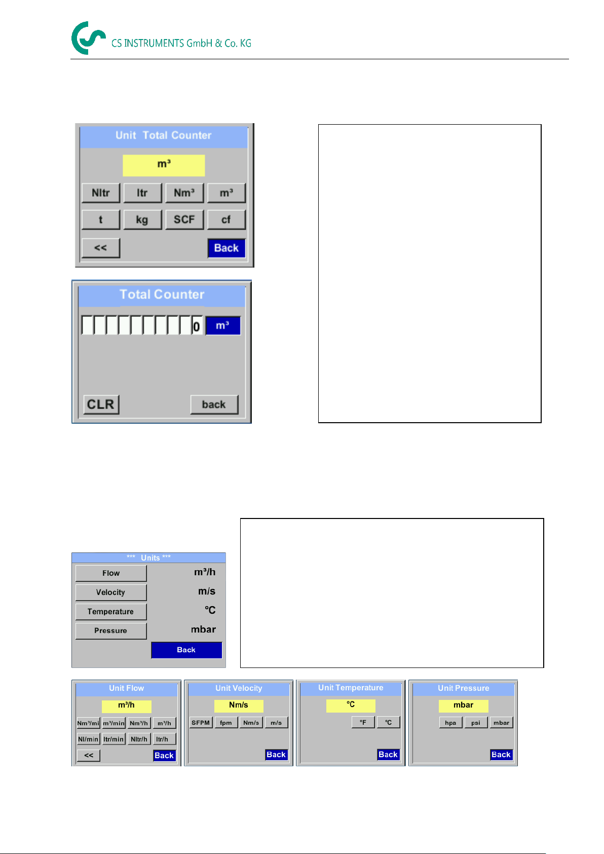
In order to change, e.g. the unit, first select by
pressing key „ “ the button “Unit” and then
key “OK”.
Select with the key „ “ the correct unit and
then confirm selection by pressing 2x „OK“.
Entering / changing the consumption counter
via button „“ , select the respective position
and activate the position with the "OK"
button.
By pressing „“ the position value is
incremented by 1. Complete with "OK" and
activate next number position.
Confirm entry by pressing „OK“.
Unit selection:
according to chapter 10.3.1.3
Direct selection of the unit button and
call of the unit page with „OK“.
To make changes to the unit for the respective measurement
value, first select by pressing „“ the field of the „measurement
value“ and activate „it with „OK“ .
Selection of the new unit with „“
In case the quantity of units selectable are not presentable on
one page, pleas move to next page by pressing „<<“ .
Confirm selection by pressing 2x „OK“.
Procedure for all 4 measurement variables is analogous.
10.3.1.2 Input / change consumption counter
Setup Sensor Setup Total Counter Unit button
Important!
When the counter reach 100000000 m³ the counter will be reset to zero.
10.3.1.3 Definition of the units for flow, velocity, temperature and pressure
Setup Sensor Setup Units
VA 525 EN V1.01 page 19 o 41
Page 20

Operation
To make changes, first select a menu with
button „“ and confirm selection by pressing
„OK“ .
Duc
Volume Type
10.3.1.4 Advanced settings
Setup Sensor Setup Advanced
10.3.1.4.1 Definition of the reference conditions
Here can be defined the desired measured media reference conditions for pressure and temperature
and times for the filter and averaging.
Factory presetting for reference temperature and reference pressure are 20 °C, 1000 hPa
All volume flow values (m³/h) and consumption values indicated in the display are
related to 20 °C and 1000 hPa (according to ISO 1217 intake condition)
Alternatively 0 °C and 1013 hPa (=standard cubic meter) can also be entered as a reference.
Do not enter the operation pressure or the operation temperature under reference conditions!
Setup Sensor Setup Advanced Ref. Settings
VA 525 EN V1.01 page 20 o 41
Page 21
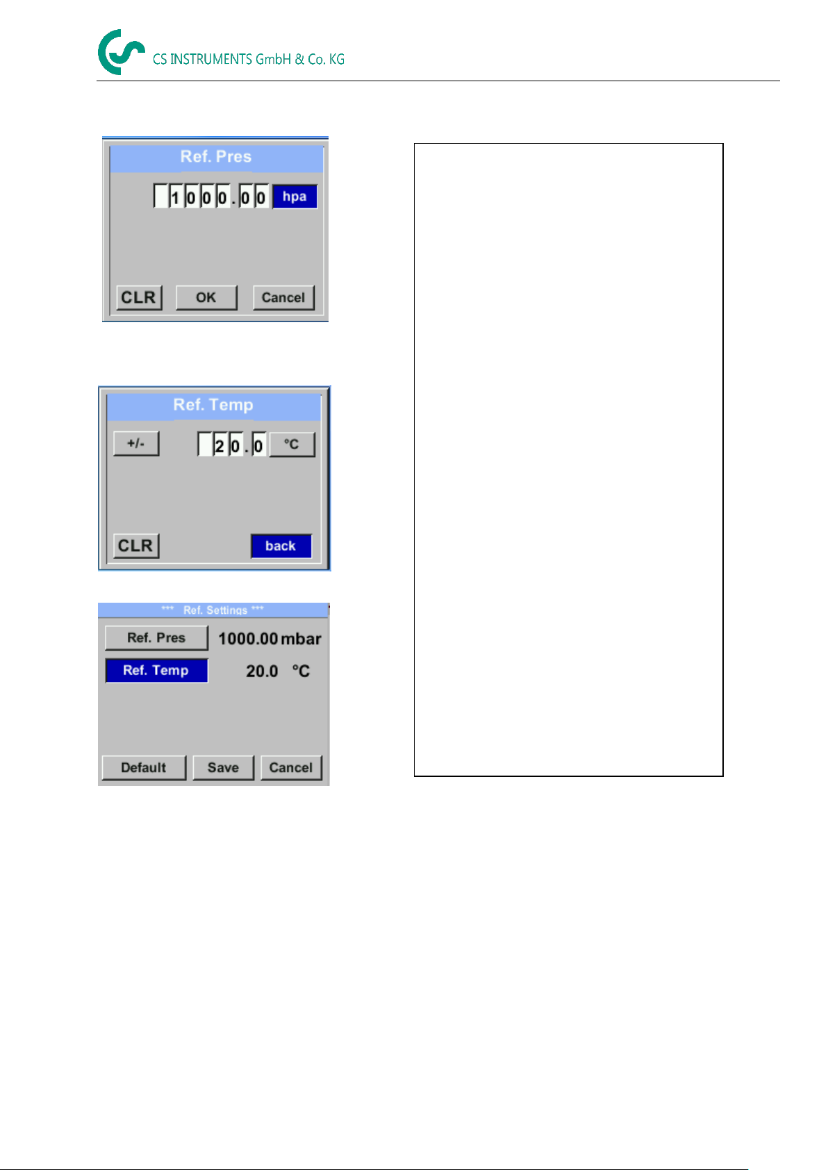
Operation
In order to change, e.g. the unit, first select by
pressing key „ “ the field “Units” and then
key “OK”.
Select with the key „ “ the correct unit and
then confirm selection by pressing 2x „OK“.
Input / change of the value by selecting the
respective position with button „“and
entering by pressing button „OK“ .
By pressing „“ the position value is
incremented by 1. Complete with „OK“ and
activate next number position.
Procedure for changing the reference
temperature is the same.
Unit selection:
according to chapter 10.3.1.3
Direct selection of the unit button and
call of the unit page with „OK".
All changes have to be stored by pressing
„Save“.
With „Default“. the sensor is reset to
calibration settings.
Setup Sensor Setup Advanced Ref. Settings Ref.Pref
Setup Sensor Setup Advanced Ref.
Settings Ref.Temp
VA 525 EN V1.01 page 21 o 41
Page 22

Operation
Under item "Filtertime" " an attenuation can
be defined.
Input values of 0 -10000 in [ms] are possible
The time period for averaging can be entered
here.
Input values of -1440 1 [minutes] are possible.
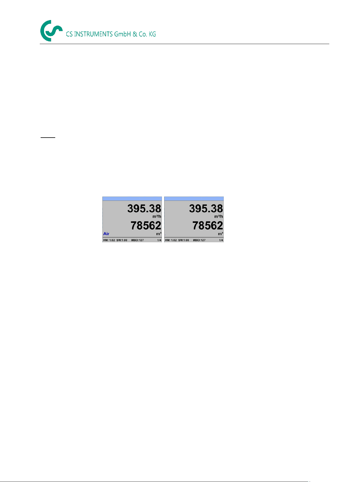
For average values see display window 3 + 4
10.3.1.4.2 Time setting for filtering
Setup Sensor Setup Advanced Ref. Settings Filtertime
Setup Sensor Setup Advanced Ref. Settings AV-Time
VA 525 EN V1.01 page 22 o 41
Page 23

Operation
To make changes, first select a menu with
button „“ and confirm selection by pressing
„OK“ .
When, without flow, the installed sensor shows
already a flow value of > 0 m³/h herewith the
zero point of the characteristic could be reset.
With selection the "ZeroPnt" key and
pressing the "OK" key, an automatic zero
point calibration is carried out.
In case there is already a calibration done, it is
indicated in menu with”calibrated”
Leave menu with button „Back“
With the low-flow cut off activated, the flow
below the defined "LowFlow Cut off" value will
be displayed as 0 m³/h and not added to the
consumption counter.
For an input / change of the value select with
the button „“ the respective number position
and activate it with „OK“.
By pressing „“ the position value is
incremented by 1. Confirm the input with „OK“
and activate next number position.
Leave menu with button „Back“
By selection of „Reset“ all settings for
„ZeroPnt“ and. „CutOff“ are reset.
Menu item to be select with button „“ and
confirm the reset with „OK“ .
Leave menu with button „Back“
calibrated
10.3.1.5 Setting of Zeropoint and Low-flow cut off
Setup Sensor Setup ZP Adjust
Setup Sensor Setup ZP Adjust ZeroPnt
Setup Sensor Setup ZP Adjust CutOff
Setup Sensor Setup ZP Adjust t Reset
VA 525 EN V1.01 page 23 o 41
Page 24

If necessary, a pressure correction can be
made by selecting "Set pressure to".
Select the menu item with the „“ key and
then select it with the "OK" key.
Enter the corresponding pressure value in the
input menu and save changes with "OK".
Press the "CLR" key to reset the value.
Exit the menu with "Cancel".
10.3.1.6 Pressur settings
Setup Sensor Setup Pressure
Operation
VA 525 EN V1.01 page 24 o 41
Page 25
Operation
For changes, e.g. the sensor ID,
first select by pressing key „“ the field
“ID” and then key “OK”.
Select the desired position by pressing the
">" and select with "OK" button.
Change values by pressing the „“ values
takeover by pressing "OK".
Inputs for baudrate, stopbit and parity is
done analogue.
By means of the button "Byte Order" it is
possible to change the data format (Word
Order). Possible formats are "ABCD" (Little
Endian) and "CDAB" (Middle Endian)
Saving the changes by pressing "Save",
therefore select it with key „“ and then
confirm it with "OK".
10.3.2 Modbus settings
10.3.2.1 Modbus RTU Setup
The Flow sensors VA 525 comes with a Modbus RTU Interface.
Before commissioning the sensor the communication parameters
Modbus ID, Baudrate, Parity und Stop bit
must be set in order to ensure the communication with the Modbus master.
Settings Modbus Setup
Default values out of factory: Modbus ID: 1
Remark: If the sensor is placed at the end of the Modbus system a termination is required. The sensors have an
internal switchable termination, therefore the 4 fastening screws from the lid are to be released and set
the internal DIP Switch to “On”.
Alternatively, a 120R resistor can be installed in the plug between pin 2 and pin 4.
It must be ensured that the connection plugs are still plugged and the gasket is installed correctly.
VA 525 EN V1.01 page 25 o 41
Baud rate: 19200
Stopbit: 1
Parity: even
Byte Order: ABCD
Page 26

Operation
Here you can set up and made a connection, with
or without DHCP, to a computer.
Remark:
With activated DHCP the automatic integration of
the sensor in an existing network is possible,
without a manual configuration.
Storing of settings by pressing “Save“
10.3.3 Ethernet (Modbus TCP)
The Flow sensors VA 525 comes optional with a Modbus TCP Interface
(HW Interface:M12 x 1 X-coded connector).
Device supports with this option the Modbus TCP protocol for communication with SCADA systems.
TCP port is set to 502 by default. Port can be changed at the sensor or using PC Service Software
Modbus device address (Unit Identifier) can be set in the range of 1- 255.
Specification and description of the Modbus protocol is free to download on: www.modbus.org.
Supported Modbus commands (functions):
Command Code Description
Function Code 3 (Read holding register)
Function code 16 (Write multiple registers)
For more details, please see VA 5xx Modbus RTU_TCP Installation V1.05
Settings Network Setup
10.3.3.1.1 Network Setup DHCP
Settings Network Setup Settings IP Address
VA 525 EN V1.01 page 26 o 41
Page 27

Operation
For manual (static) IP, the "IP Address",
"Subnet" and "Gateway" selection keys must
be selected and activated with "OK".
The first data field of the selection, in this case
the IP address, is then marked (red).
Confirm with "OK” the corresponding input menu
is opened.
By means of ">", the next data field is changed.
Select the desired position with the ">" key and
activate it with the "OK" key.
Change the values with the ">" key, and accept
the values with the "OK" key.
Procedure for "Subnet" and "Gateway" is
analogous.
Store the settings by „Save“
10.3.3.2 Network Settings static IP
Settings Network Setup Settings IP Address IP Address
Settings Network Setup Settings IP Address Sub Netz
Settings Network Setup Settings IP Address Gateway
VA 525 EN V1.01 page 27 o 41
Page 28

Operation
For changes, e.g. the sensor ID,
first select by pressing key „>“ the field “ID” and
then key “OK”.
Select the desired position by pressing the ">"
and select with "OK" button.
Change values by pressing the „>“ values
takeover by pressing "OK".
Input for the port is done analogue.
By means of the button "Byte Format" it is
possible to change the data format (Word Order).
Possible formats are "ABCD" (Little Endian) and
"CDAB" (Middle Endian)
Saving the changes by pressing "Save",
therefore select it with key „>“ and then confirm
it with "OK".
Reset to the default settings by activating "Set to
Default"-
10.3.3.3 Modbus TCP Settings
Settings Network Setup Settings IP Address MB TCP
Settings Network Setup Settings IP Address ID
Settings Network Setup Settings IP Address Port
VA 525 EN V1.01 page 28 o 41
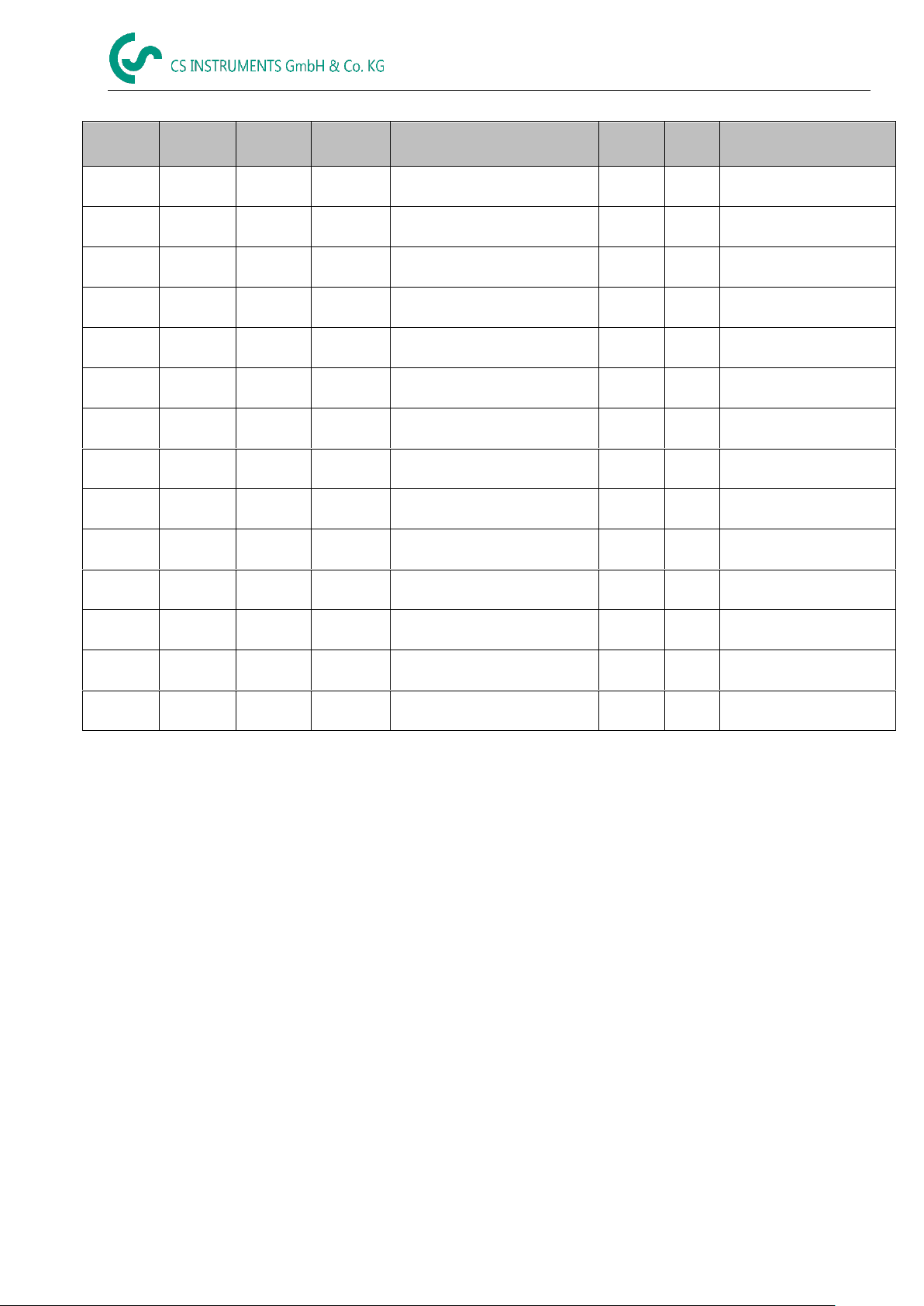
Page 29

Operation
Modbus
Register
Register
Address
No.of
Byte
Data
Type
Description
Default
Setting
Read
Write
Unit /Comment
2001
2000 2 UInt16
Modbus ID
1
R/W
Modbus ID 1…247
2002
2001 2 UInt16
Baudrate
4
R/W
0 = 1200
1 = 2400
2 = 4800
3 = 9600
4 = 19200
5 = 38400
2003
2002 2 UInt16
Parity 1 R/W
0 = none
1 = even
2 = odd
2004
2003 2 UInt16
Number of Stopbits
R/W
0 = 1 Stop Bit
1 = 2 Stop Bit
2005
2004 2 UInt16
Word Order
0xABCD
R/W
0xABCD = Big Endian
0xCDAB = Middle Endian
Modbus
Register
Register
Address
No.of
Byte
Data Type
Description
Def
ault
Read
Write
Unit /Comment
1101
1100
4
Float
Flow in m³/h
R
1109
1108
4
Float
Flow in Nm³/h
R
1117
1116
4
Float
Flow in m³/min
R
1125
1124
4
Float
Flow in Nm³/min
R
1133
1132
4
Float
Flow in ltr/h
R
1141
1140 4 Float
Flow in Nltr/h
R
1149
1148 4 Float
Flow in ltr/min
R
1157
1156 4 Float
Flow in Nltr/min
R
1165
1164 4 Float
Flow in ltr/s
R
1173
1172 4 Float
Flow in Nltr/s
R
1181
1180 4 Float
Flow in cfm
R
1189
1188 4 Float
Flow in Ncfm
R
1197
1196 4 Float
Flow in kg/h
R
1205
1204 4 Float
Flow in kg/min
R
1213
1212 4 Float
Flow in kg/s
R
1221
1220 4 Float
Flow in kW
R
10.3.3.4 Modbus Settings (2001…2005)
10.3.3.5 Values Register (1001 …1500)
VA 525 EN V1.01 page 29 o 41
Page 30
Operation
Modbus
Register
Register
Address
No.of
Byte
Data
Type
Description
Default
Read
Write
Unit /Comment
1269
1268
4
UInt32
Consumption m³ before
comma
x
R
1275
1274
4
UInt32
Consumption Nm³ before
comma
x
R
1281
1280
4
UInt32
Consumption ltr before comma
x
R 1287
1286
4
UInt32
Consumption Nltr before
comma
x
R
1293
1292
4
UInt32
Consumption cf before comma
x
R
1299
1298
4
UInt32
Consumption Ncf before
comma
x
R
1305
1304
4
UInt32
Consumption kg before
comma
x
R
1311
1310
4
UInt32
Consumption kWh before
comma
x
R
1347
1346 4 Float
Velocity m/s
1355
1354 4 Float
Velocity Nm/s
1363
1362 4 Float
Velocity Ft/min
1371
1370 4 Float
Velocity NFt/min
1419
1418 4 Float
GasTemp °C
1427
1426 4 Float
GasTemp °F
Remark:
For DS400 / DS 500 / Handheld devices - Modbus Sensor Datatype
„Data Type R4-32“ match with „Data Type Float“
For more additional Modbus values please refer to
VA5xx_Modbus_RTU_Slave_Installation_1.04_EN.doc
VA 525 EN V1.01 page 30 o 41
Page 31
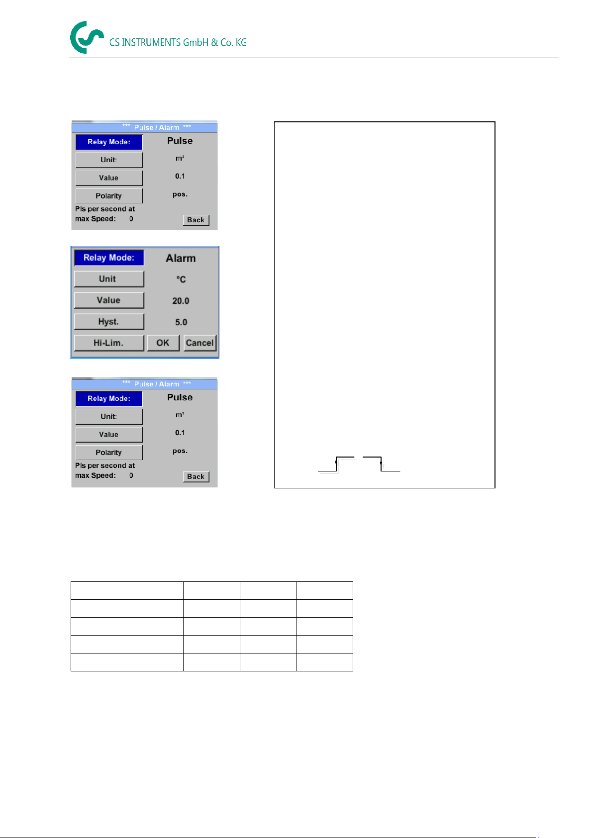
Pulse value
[m³ /h]
[m³ /min]
[l/min]
0.1 ltr / Pulse
18
0,3
300
1ltr / Pulse
180
3
3000
0.1m³ / Pulse
18000
300
300000
1 m³ / Pulse
180000
3000
3000000
The galvanically isolated output can be
defined as pulse- or alarm output.
Selection of field „Relay Mode” with key „“
and change modus by pressing key „OK“.
For alarm output following units could be
chosen: Nm/s, m/s, Nm³/h, m³/h, Nltr/h, ltr/h,
Nm³/min, m³/min, kg/s, kg/min,lb/s, lb/min,
lb/h, SFPM, fpm, °C, °F
„Value“ defines the Alarm value, „Hyst.“
defines the desired hysteresis and with „Hi-
Lim“ or. „Lo-Lim“ the alarm settings when
the alarm is activated
Hi-Lim: Value over limit
Lo-Lim: Value under limit
For the pulse output following units could be
chosen: kg, cf, SCF, ltr, Nltr, Nm³ and m³. The
pulse value definition to be done in menu
„Value“ . Lowest value is depending on max.
flow of sensor and the max frequency of pulse
output of 50Hz.
With „Polarity“ the switching state could be
defined. Pos. = 0 1 neg. 1 0
pos
neg
open
closed
10.3.4 Pulse /Alarm
Settings Pulse/ Alarm
Operation
10.3.4.1 Pulse output
The maximum frequency for pulse output is 50 pulses per second (50Hz).
The Pulse output is delayed by 1 second.
Table 1 Maximum flow for pulse output
Entering pulse values that are not allow a presentation to the full scale value, are not allowed. Entries are
discarded and error message displayed.
VA 525 EN V1.01 page 31 o 41
Page 32

To make changes, first select a menu with
button „“ and confirm selection by pressing
„OK“ .
It is possible to define a password. The
required password length is 4 digits.
Please select with button „“ a figure and
confirm it with „OK“ .Repeat this 4 times.
With „“ the last figure could be deleted.
Password input have to be inserted twice.
Confirmation of input/password by pressing
„OK“.
Factory settings for password at the time of
delivery: 0000 (4 times zero).
Currently 4 languages have been implemented
and could be selected with button „“
Change of language by confirming with “OK”.
Leaving the menu with button “back”.
10.3.5 User Setup
10.3.5.1 Password
Settings UserSetup Password
Operation
10.3.5.2 Language
Settings UserSetup Language
VA 525 EN V1.01 page 32 o 41
Page 33

Operation
By pressing „Factory Reset“ the sensor is set
back to the factory settings.
With the button „-“ and with button „+“ it is
possible to adjust the backlight / display
brightness.The actual / adjusted backlight
brightness is showed in the graph „Backlight.“
By activation “Dimming after” and entering a
time a display dimming could be set.
With „Rotate Screen“ the display information
could be rotated by 180°.
By activation of „Key Lock“ the operation of
the sensor locked.
Unlocking the keyboard is only possible by
restarting the sensor and calling the operating
menu within the first 10s. To do this, use the
"OK" button to enter the operating menu during
this period
10.3.5.3 Display / Touch
Settings UserSetup Display / Touch
10.3.6 Advanced
Settings Advanced
VA 525 EN V1.01 page 33 o 41
Page 34

0.000 m³/h
1098.9 m³/h
169,8 m/s 1098.9 m³/h
1098.9 m³/h
0.000 m³/h
169,8 m/s 1098.9 m³/h
To make changes, first select a menu with button
„“ and confirm selection by pressing „OK“ .
The 4-20 mA Analogue output of the Sensor VA 525 can
be individually adjusted.
It is possible to assign following values „Temperature“,
„Velocity“ und „Flow“ to the channel CH 1.
To make changes, first select the value item with button
„“ .and confirm
Moving between the different measurements values or
to deactivate the 4-20mA with setting to „unused“ by
pressing „OK“.
To the selected measurement value a corresponding /
appropriate unit needs to be defined. Select „Unit“ with
„“ and open menu with „OK“.
Select required unit with „“ and take over by pressing
„OK“.
Here e.g. for the measurement value Flow, procedure
for the other measurements values is analog.
For saving the changes done press button „Save“ to
discard the changes press button “Cancel”.
Leaving the menu with „Back“.
10.3.7 4 -20mA
Settings 4-20mA
Settings 4-20mA Channel 1
Operation
VA 525 EN V1.01 page 34 o 41
Page 35

Operation
End Range 169,8m/s 1098,9 m³/h
1098,9 m³/h
The scaling of the 4-20mA channel can be done
automatically "Auto Range = on" or manual "AutoRange
= off" .
With button „“ select the menu item „AutoRange“
select with „OK“ the desired scaling method.
(Automatically or manually)
In case of AutoRange = off with „Scale 4mA“ und
„Scale 20mA“ the scale ranges needs to be defined.
Select with button „“ the item „Scale 4mA“ or „Scale
20mA“ and confirm with „OK“ .
Input of the scaling values will be analogous as
described before for value settings.
Using „CLR“ clears up the complete settings at once.
For „Auto on“ , the max. scaling is calculated based on
the inner tube diameter, max. measurement range and
the reference conditions settings.
Take over of the inputs with „Save“ and leaveing the
menu with „Back“.
This determines what is output in case of an error at the
analog output.
2 mA Sensor error / System error
22 mA Sensor error / System error
None Output according Namur (3.8mA – 20.5 mA)
< 4mA to 3.8 mA Measuring range under range
>20mA to 20.5 mA Measuring range exceeding
To make changes first select a menu item "Current Error"
with button „“ and then select by pressing the „OK“
the desired mode
For saving the changes done press button „Save“ to
discard the changes press button “Cancel”.
Leaving the menu with „Back“.
Settings 4-20mA Channel 1 AutoRange
Settings 4-20mA Error Current
VA 525 EN V1.01 page 35 o 41
Page 36

Run Time: 2d 21h 23m 12s
Vin: 23,8V Temp: 35,8
92,7 m/s 600m³/h
20 °C
53,1 mm
23 °C
10
Here you get a brief description of the sensor data
incl. the calibration data.
Under Details, you are able to see in addition the
calibration conditions.
10.3.8 VA 525 Info
Settings Info
Operation
VA 525 EN V1.01 page 36 o 41
Page 37
The Sensor offers two possibilities for coding the
Value Informaition Field (VIF).
Primary VIF (The units and multiplier
correspond to MBus specification 4.8
chapter 8.4.3
Plain text VIF ((units are transmitted as
ASCCII characters. So units that are not
included in MBus specification chapter 8.4.3
are possible
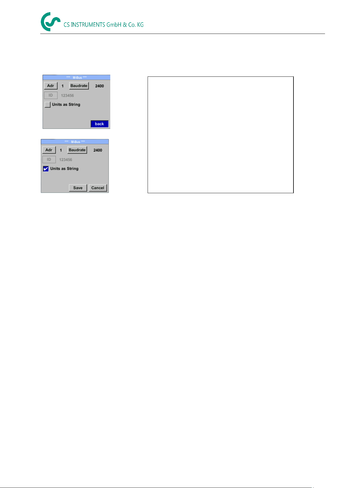
Switch to Plain Text VIF by activation of „Units as
String“.
10.4 MBus
Settings MBus
Operation
10.4.1 Default Settings communication
Primary Adress*: 1
ID: Serialnumber of Sensor
Baud rate*: 2400
Medium*: depending on medium (Gas or Compressed Air)
Manufacturer ID: CSI
VIF coding: Primary VIF
Both addresses, Primary address and ID, could be automatic searched in the M-Bus system.
10.4.2 Default values transmitted
Value 1 with [Unit]*: Consumption [m³]
Value 2 with [Unit]*: Flow [m³/h]Consumption [m³]
Value 3 with [Unit]*: Gas temperature [°C]
*All Values could be changed / preset in production or with CS Service software (Order-No. 0554 2007)
VA 525 EN V1.01 page 37 o 41
Page 38
Status- / Error messages
*** VA 520 ***
CAL
*** VA 520 ***
Direction
11 Status / Error messages
11.1 Status messages
CAL
On the part of CS Instruments GmbH & Co.KG a regular re-calibration is recommended, see chapter 13.
At delivery, the date at which the next recalibration is recommended is internally entered.
When this date is reached, a message appears in the display with the status message „CAL“.
Note: The measurement will continue without interruption or restriction.
Direction
When used in conjunction with a direction switch VA409, the status message "Direction" is displayed
in case of opposite flow direction and no measurement may take place.
Status messages:
VA 525 EN V1.01 Page 38 of 41
Page 39

*** VA 520 ***
Low Voltage
*** VA 520 ***
Heater Error
*** VA 520 ***
Internal Error
*** VA 520 ***
Temp out of Range
*** VA 520 ***
Low Voltage 4.20mA
VA 525
VA 525
VA 525
VA 525
VA 525
Status- / Fehlermeldungen
11.2 Error messages
Low Voltage
If the supply voltage is less than 11V, the warning message „Low Voltage“ is displayed.
This means that the sensor can no longer work / measure correctly and thus there are none
measured values for flow, consumption and speed are available.
Heater Error
The error message „Heater Error“ occurs in case of failure of the heating sensor.
Internal Error
In the case of this message „Internal Error“, the sensor has an internal read error on e.g. EEProm, AD converter
etc. detected.I
Temp out of Range
At media temperatures outside the specified temperature range, the status message „Temp out of Range“
occurs.
This temperature overshoot leads to incorrect measurement values (outside the sensor specification).
Low Voltage 4-20mA
For sensors with a galvanically isolated 4-20mA output, a min. Supply voltage of 17.5V is required. If this value is
undershot, the error message „Low Voltage 4-20mA“ is displayed.
Error messages:
VA 525 EN V1.01 page 39 o 41
Page 40

Maintenance / warranty
12 Maintenance
The sensor head should be checked regularly for dirt and cleaned if necessary. Should dirt, dust or oil
accumulate on the sensor element, a deviation will occur in the measuring value. An annual check is
recommended. Should the compressed air be heavily soiled this interval must be shortened.
13 Cleaning of the sensor head
The sensor head can be cleaned by carefully moving it in warm water with a small amount of washingup liquid. Avoid physical intervention on the sensor (e.g. using a sponge or brush). If soiling cannot be
removed, service and maintenance must be carried out by the manufacturer.
14 Re-Calibration
If no customer specifications are given then we recommend to carry out calibration every 12 months.
For this purpose the sensor must be sent to the manufacturer.
15 Spare parts and repair
For reasons of measuring accuracy spare parts are not available.
If parts are faulty, they must be sent to the supplier for repair.
If the measuring device is used in important company installations, we recommend keeping a spare
measuring system ready.
16 Calibration
According to DIN ISO certification of the measuring instruments we recommend to calibrate and if
applicable to adjust the instruments regularly from the manufacturer. The calibration intervals should
comply with your internal specification. According to DIN ISO we recommend a calibration interval of
one year for the instrument VA 525.
On request and additional payment, calibration-certificates could be issued.
The precision is given due to use DKD-certified flow meters and verifiable
17 Warranty
If you have reason for complaint we will of course repair any faults free of charge if it can be proven
that they are manufacturing faults. The fault should be reported immediately after it has been found
and within the warranty time guaranteed by us. Excluded from this warranty is damage caused by
improper use and non-adherence to the instruction manual.
The warranty is also cancelled once the instrument has been opened - as far as this has not been
mentioned in the instruction manual for maintenance purposes - or if the serial number in the
instrument has been changed, damaged or removed.
The warranty time for the VA 525 is 12 months. If no other definitions are given the accessory parts
have a warranty time of 6 months. Warranty services do not extend the warranty time.
If in addition to the warranty service necessary repairs, adjustments or similar are carried out the
warranty services are free of charge but there is a charge for other services such as transport and
packaging costs. Other claims, especially those for damage occurring outside the instrument, are not
included unless responsibility is legally binding.
After sales service after the warranty time has elapsed
We are of course there for you even after the warranty time has elapsed. In case of malfunctions,
please send us the instrument with a short-form description of the fault. Please do not forget to
indicate your telephone number so that we can call you in case of any questions.
VA 525 EN V1.01 Page 40 of 41
Page 41

CE Conformity
Elektromagnetische Verträglichkeit
Electromagntic compatibility
2014/30/EU
2014/30/EC
RoHS (Restriction of certain Hazardous Substances)
2011/65/EC
EMV-Anforderungen
EMC requirements
EN 55011: 2016
EN 61326-1: 2013-07
KONFORMITÄTSERKLÄRUNG
DECLARATION OF CONFORMITY
Wir CS Instruments GmbH & Co.KG
We Am Oxer 28c, 24955 Harrislee
Erklären in alleiniger Verantwortung, dass das Produkt
Declare under our sole responsibility that the product
Verbrauchs-/ Durchflusssensor VA 525
Flow Sensor VA 525
den Anforderungen folgender Richtlinien entsprechen:
We hereby declare that above mentioned components comply with requirements of the following EU directives:
Angewandte harmonisierte Normen:
Harmonised standards applied:
Anbringungssjahr der CE Kennzeichnung: 18
Year of first marking with CE Label: 18
Das Produkt ist mit dem abgebildeten Zeichen gekennzeichnet.
The product is labelled with the indicated mark.
Harrislee, den 23.11.2018 __________________
Wolfgang Blessing Geschäftsführer
VA 525 EN V1.01 Page 41 of 41
 Loading...