

Page 1

DS 350-P
Operation manual
Page 2

DS 350-P DS 350-P
DS 350-P English, V1.2, 13.09.13 DS 350-P English, V1.2, 13.09.13
0970 0065 0970 0065
2 23
Features
•
Connectable sensors for all required measurement tasks (air flow, air con sumption, power consumption, pressure, temperature and many more)
•
Up to 24 inputs through extension boxes
•
Several loggers can be combined: no need to have long cables from the sensor
to the logger
•
Third party sensors can be easily connected
•
Up to 100 million records in SD card
•
Full software package includes:
- CSM-S for basic analyzes
- CAA for compressed air audit analyzes
•
No
time
consuming data transfer as data is stored on SD card and can be
moved to PC
The operating instructions must be read in full and carefully observed before starting
up the device. The manufacturer cannot be held liable for any damage which occurs
as a result of non-observance or non-compliance with this manual.
Should the device be tampered with in any manner other than a procedure which is
described and specified in the manual, the warranty is cancelled and the manufacturer is exempt from liability.
The device is destined exclusively for the described application.
CS Instruments offers no guarantee for the suitability for any other purpose and is not
liable for errors which may have slipped into this operating manual. They are also not
liable for consequential damage resulting from the delivery, capability or use of this
device.
Important information
Page 3

2. Overview
1
3 2 4
5
1
3
2
4
5
SD card slot
Keyboard for user interface operations
USB port
SD card ejector tool
Battery gauge
6
6
On/Off button
3
Page 4

DS 350-P DS 350-P
DS 350-P English, V1.2, 13.09.13 DS 350-P English, V1.2, 13.09.13
0970 0065 0970 0065
Casing
Size: 265 x 220 x 150 mm
Sensor inputs
CS flow/dew point sensors
Modbus sensor modules
Process signal
Pulse
P4 P6 P8
2x 2x 2x
2x 2x 2x
2x 4x
2x
Interface
USB to PC
Keyboard
4 keys
Power supply 100 .… 240 VAC / 50 VA, 47-60 Hz
Display Graphic display, 220 x 140 pixels, with back light
Accuracy
Channel 1+2: see sensor specifications
Channel 7+8: see sensor specifications
Channel 3-6: see technical data process signales
Internal battery Rechargable for up to 8 hours operation.
Charging time ~ 3 hours
Data logger Data is stored in 4G SD card, up to 100 million values
Technical data
Sensor and mains connection at the side
CS flow/dew point sensors 1+2
Modbus sensor modules 7+8
Process signals 3-6
Pt100 3+4
Pulse 5+6
Sensor type Channel
4
Scope of delivery
CS provides a warranty for this product of 24 months covering the material and work-
manship under the stated operating conditions from the date of delivery.
Please report any findings immediately and within the warranty time guaranteed by
us.
Excluded from this warranty is damage caused by improper use and non-adherence
to the instruction manual.
The warranty is also cancelled once the measuring instrument has been opened pro-
vided this is not described in the instruction manual for maintenance purposes. This is
also the case if the serial number has been changed, damaged or removed.
If in addition to the warranty service necessary repairs, adjustments or similar are
carried out, the warranty services are free of charge but there is a charge for other
services such as transport and packing costs. Other claims, especially those for dam-
age occurring outside the instrument are not included unless responsibility is legally
binding.
ATTENTION: Batteries have a reduced warranty time of 12 months.
Warranty
1 3 5 7 8
2 4 6
Page 5

Settings
Complete settings can be changed through user interface
at DS 350-P
Sensor connector
Round lockable connectors, 5 pole
Operating temperature
0 ... 50 ºC
Transport temperature
-20 ... 50 ºC
Weight
2400 g
Sensor inputs 0-1V, 0-10V
0-20 mA, 4-20 mA
Pt100/Pt1000
Pulse
Measuring range 0-20 mA: 0… 21 mA
0-1 V: 0...1.05 V
0-10 V: 0...10.5 V
Pt100: -200…+850 ºC
Pt1000: -200…+850 ºC
Pulse: 0...100 Hz, High > 5V, Low < 2 V
I < 5 mA, V < 30V
Accuracy 0-20 mA: 0.01 mA
0-1 V: 1 mV
0-10 V: 0.01 V
Pt100: 0.2 ºC
Pt1000: 0.2 ºC
Pulse 1 digit
Resolution 0-20 mA: 0.001 mA
0-1 V: 0.05 mV
0-10 V: 0.5 mV
Pt100: 0.1 ºC
Pt1000: 0.1 ºC
Pulse: 1 digit
Technical data process signals
Page 6

DS 350-P DS 350-P
DS 350-P English, V1.2, 13.09.13 DS 350-P English, V1.2, 13.09.13
0970 0065 0970 0065
Start DS 350-P
DS 350-P is equipped with an internal rechargeable battery. This battery is intended to
supply the system with power during power loss or for short term measurement where
a mains supply is inconvenient. However it‘s recommended to use the mains supply
whenever available to ensure a fully charged battery and to ensure a safe and long
term measurement.
Input impedance 0-20 mA: ~50 Ω
0-1 V: 60 MΩ
0-10 V: 1 MΩ
Pt100: N/A
Pt1000: N/A
Pulse: 1000R
Sensor excitation 24VDC / 20 W (total available power for sensor supply)
Probe connection and power supply
Please connect all sensors before switching on DS 350-P. CS flow / dew point sensors
are detected automatically when connected. The same applies to CS sensor extension
modules (power meter, us flow meter, analogue extension) which are connected to
channel 7 + 8.
Process signals can not be detected automatically. The user has to select the appropriate sensor type from the sensor selection menu (Sensors—Select sensor type).
The On/Off switch has following functions when powered off:
1. A short pressing of the button will activate the battery
gauge display and the charging status can be read.
2. Keep the button pressed for 2 seconds and the device
will start up
3. To switch off the device keep the button pressed for 2
seconds.
6
Order information
0560 0550 DS 350-P4, 4 channel data recorder, incl. Software, SD card, power cord,
0560 0551
0560 0552 DS 350-P8, 8 channel data recorder, incl. Software, SD card, power cord,
Flow sensors
0695 0122
0695 0453
0699 0419
0694 1886
0694 0356
0554 0504 Clamp on amp sensor, 1000 A, 5 m cable with connector
0604 0100
0554 6003 Compression fitting, 6 mm, G ½" thread, 0.6 MPa
0554 6004 Compression fitting, 6 mm, G ½" thread, 1.6 MPa
0554 0034 Portable power meter CS 110-P, Modbus/RTU, including 4 test leads, 4
0554 0061 Current clamp sensor, 1.8 m cable, 200/1 A, connectable to CS 110-P (1
Page 7

Operation
Description of display icons
One page of measurement value will be shown at a time. User
can use or key to scroll through all
available value.
Page view indication: This “ Page view indication ” shows
the current display measurement value page no., and the total
measurement value page count available .
Indicate there are totally 8 page
measurement value available.
Indicate the measurement value
display page 1 of 8 .
Status icon detail description:
Status icon shows different status of the system.
Low battery icon: it shows when internal battery low.
(Please contact service.)
USB connection icon: icon shows when DS 350-P connected to PC via USB .
When DS 350-P starts up it will display the
start-up screen for a few seconds. During this
time the sensor connections are established
and a few other initialisation tasks are performed.
If there are any sensors connected, DS 350-P
will connect to them automatically and start to
display real time measurement values acquired
from those sensors. The measurement values
may be displayed on more than one page. To
see another page, just press the arrow buttons
on the key board .
Page 8
DS 350-P DS 350-P
DS 350-P English, V1.2, 13.09.13 DS 350-P English, V1.2, 13.09.13
0970 0065 0970 0065
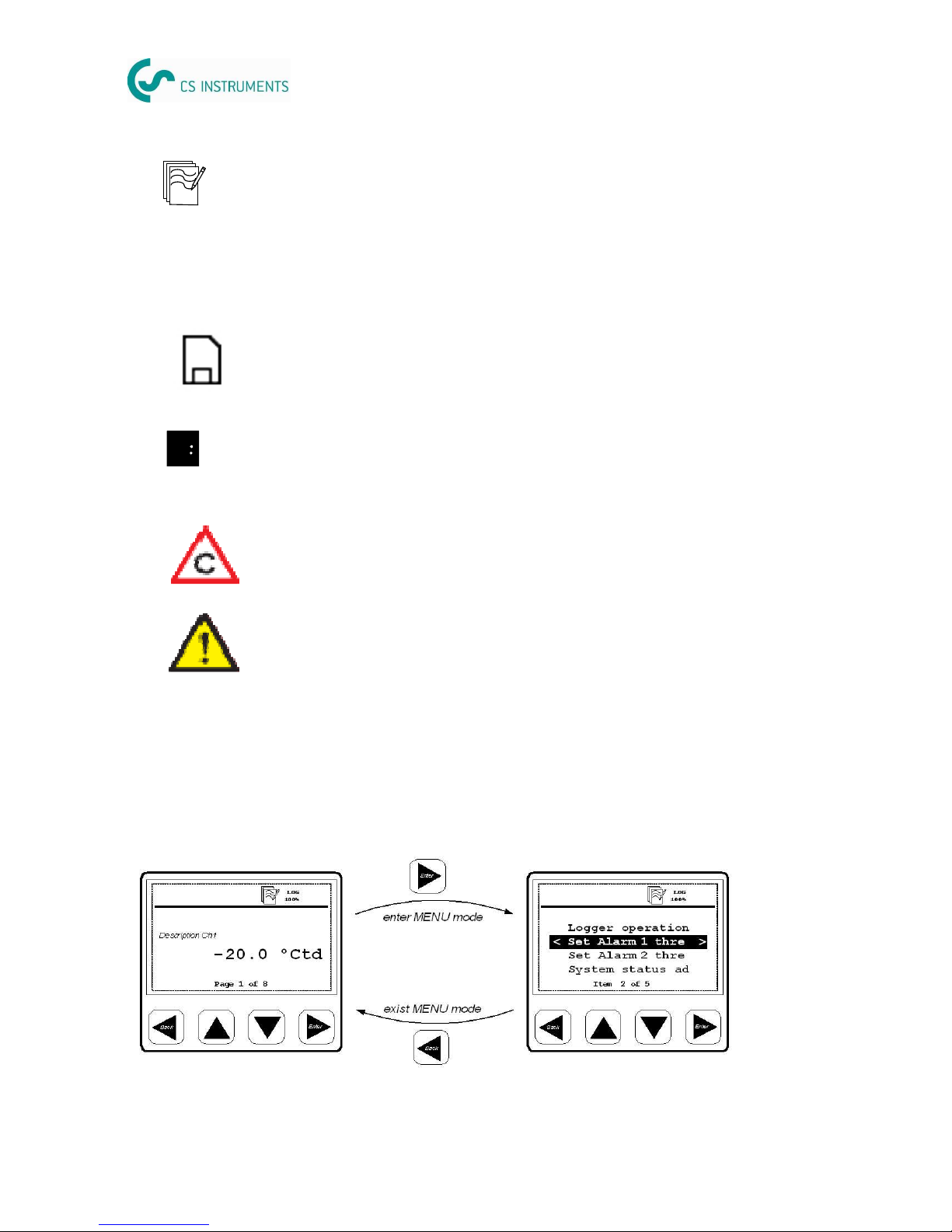
5.2 Basic key operation
Basic concept for MENU mode key operation
The number indicates the sensor terminal connection. If it’s inverse this channel is set to be logged. It will start blinking as soon the logger is activated.
1
The calibration is expired. It‘s recommended to re-calibrate the sensor unit.
Contact CS Service
General error indication. Please note down the error codes and contact CS
Service
8
LOG
100%
Logger module status:
- WAIT: Time start condition set, and wait for start logging
- LOG: Logger module is doing data logging
- STOP: Logging is stopped
- DEL: Logger is deleting protocol data
- ERR: Error occur during data logging.
Logger module free memory in percentage , or CYCLE when logger memory
in circular mode.
SD card is inserted. Please ensure that this symbol is shown before sarting
data logging.
Connecting analogue sensors
All CS sensors will fit to the designated terminal.
In case the user want to connect other analogue sensors such as Pt100, Pt1000 (3-
wire), 0-20 mA, 4-20 mA, 0-1 V and 0-10 V, Pulse types, this can be done through con-
nector 3—6 according to the pinning shown in the table above.
DS 350-P can also supply the external sensor with 24 VDC. Please ensure that the
power drawn is within the allowed limits (see next chapter for more details).
If an analogue sensor is not in the selection list found when assigning the sensor type
in the sensor setting menu, it’s required to use the software CSC-350. The software
can be downloaded from www.csinstrument.com.
Through this software further analogue sensors which are not included in the standard
package can be added into the selection list.
Page 9

Typical display layout for option selection:
The radio button for selecting the option
.
- Radio button style for de-selected item
- Radio button style for selected item
Procedure to select and enable new option
1) Use or key to select the desired option being
enable
2) Use the key to enable the new selected
For leaving the exist option:
1) Use the key to go back to last menu level without enable
the selected option.
Typical menu display layout and keys description :
The current select menu item
will be shown in negative color.
If there is a “ < ” sign, it
means we can exit the current
menu or go up one level from
the current menu level.
If there is a “ > ” sign, it
means we can go into the
submenu
Selectable menu item, it shows
5 items at a time. If the total
items in the current menu level
is more then 4 items, the menu
item should scroll over.
It tells how many item exist in the
current menu, and which no. of item
is currently selected
9
- use these keys to
- browse and select different items in menu, and scroll
through different pages of measurement value display
- use these keys to alter or adjust the setting option or number
ing
- use this key to
- exit the current menu level
- leave setting state, without saving the changes
- use this key
- to enter to submenu or next menu level of the current
selected menu item
- use it to confirm the setting change or enable an option in all
setting state
Page 10

DS 350-P DS 350-P
DS 350-P English, V1.2, 13.09.13 DS 350-P English, V1.2, 13.09.13
0970 0065 0970 0065
10 15
Operation in detail
By pressing the <Enter> key the menu can be accessed. DS 350-P has following main
menus:
Logger
Files
Sensors
Communication
System
Typical display layout for altering or adjusting the number setting :
Example: Time and data setting
1) Use and key adjust the time
2) Use key to move from HOUR -> MINUTE -> SEC
OND setup
3) After the SECOND setting and press the key to finalize
the setup, or press to exit from the “Time and date set
ting” menu and without saving the new setting
CS 110-P requires a few selections in order to measure. In the sensor menu please
select CS 110-P and make following settings.
Sensor type: choose the the right CT type (200A, 500 A, 1000 A)
Sensor status: This menu will provide sensor information about the connection.
Please check here for details in case the displayed values are
shown as “—-.-”. Most likely it’s caused by a wrong connection of
the CTs or Voltages.
These settings are stored permanently inside DS 350-P and need only to be changed
if there is a change in these parameters.
CS power meter CS 110-P
DS 350-P can support up to two Modbus sensors connected to connector 7 and 8.
For the communication there is a fixed parameter setting which can be viewed in the
communication menu. Any third party sensor connected to these inputs need to have
it’s communication parameters set like that.
CS provides following Modbus sensors:
- Power meter CS 110-P
- Liquid flow (US clamp meter) CS 460-P
- 8 channel analogue extension module
CS Modbus sensors are detected automatically (plug & play).
For third party sensors its required to use the configuration software CSC-350 to cre-
ate the sensor and download it into DS 350-P. After the download this sensor is then
available for selection from the menu.
Modbus sensors
•
•
Page 11

11
Logger
DS 350-P includes a data logger that can record up to 100,000,000 measurement
values. In order to configure the logger function and to activate/deactivate it, there
are several functions available which are explained below:
Key start/stop logging
Starts or stops the data recording. Whenever a new recording
is started a new file is created in the memory.
Select logging
channel
Those channels which should be recorded with the data logger
must be selected first. For example, if Flow is selected to be
recorded the flow value of all connected flow sensors will be
recorded. Attention: sensors connectable on connector 3...6
are shown as they have been selected in the sensor setting
menu.
Set logger memory
mode
It can be selected to stop logging when memory is full, or the
“wrap around mode” can be chosen, which then will overwrite
the oldest values as soon the memory is full.
Set logging rate and
averaging
The logging rate defines the interval data should be recorded in
the memory. It will record from every activated channel a sample. The averaging option can be used to calculate an average
value. I.e. DS 350-P is measuring every 1 second and if the
logging rate is 10 seconds, it will calculate an average value
out of the last 10 measurement values and store it as a recorded sample.
Logger status
Shows the start time and the number of samples recorded up
to now. Can only be entered if a logging has been started.
Set time start
condition
DS 300-P can be programmed to start at a certain time. Programmed time must be 10 seconds later than the system time.
To ensure a reliable logger operation please ensure following:
- Don't remove the SD card during logging
- Format a NEW SD card before using it
- SD cards with more than 4 GB size should be partitioned to reduce the size to 4 GB.
Page 12

DS 350-P DS 350-P
DS 350-P English, V1.2, 13.09.13 DS 350-P English, V1.2, 13.09.13
0970 0065 0970 0065
12
Sensors
The following chapter describes the settings related to the sensor itself, which can be
changed on the DS 350-P menu. For that purpose select in the menu the function
“Sensors”.
The next screen will show all detected flow/dew point sensors of connector 1 and 2.
Sensors of connector 7+8 are also auto-detected as long it’s a CS sensor (power
meter, US flow meter, analogue extension), but other Modbus sensors are shown as
selected from the menu. Connector 3 to 6 show also the selected analogue sensors.
The next chapters describe the available settings of the different sensors.
For CS flows sensors following settings can be made:
Note:
Reference pressure and reference temperature are not related to the actual process
pressure or temperature. They are used to calculate the standard flow at standard
conditions, for example: 1000 hPa, 20 ºC.
Changes on the sensor settings are downloaded immediately into the sensor as soon
the changes are confirmed by pressing <Enter>.
The gas type can not be changed if the connected sensor was calibrated in “real gas”
Flow sensor settings
Files
DS 350-P stores the recorded measurement values on a SD card which is accessible
at the front side. In this menu the available functions are as follows:
Recorded files
Lists all recorded files on the SD card. After selecting a particular file, the file information such as start time, location name
and samples recorded can be shown.
It also allows the deletion of recorded files.
SD card status
Displays the available memory and total memory size
Format SD card
Is used to format the SD card. ATTENTION: formatting will
delete the contents on the card completely and it can not be
recovered!
CS Flow sensors connected to port 3-6
Flow sensors connectable to the ports 3 … 6 must be configured first by connecting
them to either port 1 or 2. Only these 2 ports a capable to write sensor settings into
the sensor. Port 3 and 4 can measure flow only and ports 5 and 6 can measure flow
and consumption. To do the settings follow these steps:
•
•
•
•
Page 13

13
For CS flows sensors following settings can be made:
•
Set tube diameter: for flow calculation
•
Set total consumption: counter can be set to any value
•
Set flow unit: Selection of the desired flow unit
•
Set consumption unit: selection of the desired consumption unit
•
Set reference pressure: in order to calculate the standard flow
•
Set reference temperature: in order to calculate the standard flow
•
Set gas type: Select the gas which is measured with the flow sensor.
Note:
Reference pressure and reference temperature are not related to the actual process
pressure or temperature. They are used to calculate the standard flow at standard
conditions, for example: 1000 hPa, 20 ºC.
Changes on the sensor settings are downloaded immediately into the sensor as soon
the changes are confirmed by pressing <Enter>.
The gas type can not be changed if the connected sensor was calibrated in “real gas”
Flow sensor settings
CS Flow sensors connected to port 3-6
Flow sensors connectable to the ports 3 … 6 must be configured first by connecting
them to either port 1 or 2. Only these 2 ports a capable to write sensor settings into
the sensor. Port 3 and 4 can measure flow only and ports 5 and 6 can measure flow
and consumption. To do the settings follow these steps:
•
Connect the sensor to port 1 or 2 and perform the settings in the menu as it
would remain connected to this port (diameter, units, etc.)
•
When finished, select in the menu “copy settings” together with the desired
port or terminal (3...6)
•
Switch off DS 350-P and move the flow sensor connection to the selected
port.
•
Done! You will see a “CS flow sensor “ then in the sensor channel list at the
selected port with the correct unit and scaling.
Page 14

DS 350-P DS 350-P
DS 350-P English, V1.2, 13.09.13 DS 350-P English, V1.2, 13.09.13
0970 0065 0970 0065
14
Logger
DS 350-P includes a data logger that can record up to 100,000,000 measurement
values. In order to configure the logger function and to activate/deactivate it, there
are several functions available which are explained below:
Key start/stop log-
ging
Select logging
channel
Set logger memory
mode
Set logging rate and
averaging
Logger status
Set time start
condition
DS 350-P has up to 4 analogue input channels at connector 3 to 6. These channels
don’t have an automatic sensor detection, the sensors need to be manually selected.
Following settings are available:
•
Select sensor type: Ds 350-P stores up to 15 different analogue sensors which
can be selected from the list
•
Show sensor setting: the details of the sensor settings such as: sensor type,
unit, resolution, input scaling and calibration offset can be viewed.
Analogue sensor settings
To ensure a reliable logger operation please ensure following:
- Don't remove the SD card during logging
- Format a NEW SD card before using it
- SD cards with more than 4 GB size should be partitioned to reduce the size to 4 GB.
For CS dew point sensors following settings are available:
•
Set moisture unit: (ºCtd, g/m3, g/kg, ppm etc.). Attention: g/m3, mg/m3, ppm[V]
and atmospheric dew point require to enter a reference pressure.
•
Set reference pressure: required for g/m3, mg/m3, ppm[V] and atmospheric
dew point calculation. The pressure has to be entered as absolute pressure (not
gauge pressure!)
For the unit atmospheric dew point and ppm[V], the line pressure (absolute)
has to be entered.
For the unit g/m3, mg/m3, if the calculate should be done under line pressure
conditions, a reference pressure of 1013 hPa has to be entered.
If the calculation should be done for atmospheric conditions, the line pres
sure (absolute) has to be entered.
Dew point sensor settings
In case the destination port is 5 or 6 an additional channel for the counter is added to
the channel list.
Through these steps up to 6 CS flow sensor can be configured and operated at one
DS 350-P8.
Page 15

CS 110-P requires a few selections in order to measure. In the sensor menu please
select CS 110-P and make following settings.
Sensor type: choose the the right CT type (200A, 500 A, 1000 A)
Sensor status: This menu will provide sensor information about the connection.
Please check here for details in case the displayed values are
shown as “—-.-”. Most likely it’s caused by a wrong connection of
the CTs or Voltages.
These settings are stored permanently inside DS 350-P and need only to be changed
if there is a change in these parameters.
CS power meter CS 110-P
DS 350-P can support up to two Modbus sensors connected to connector 7 and 8.
For the communication there is a fixed parameter setting which can be viewed in the
communication menu. Any third party sensor connected to these inputs need to have
it’s communication parameters set like that.
CS provides following Modbus sensors:
- Power meter CS 110-P
- Liquid flow (US clamp meter) CS 460-P
- 8 channel analogue extension module
CS Modbus sensors are detected automatically (plug & play).
For third party sensors its required to use the configuration software CSC-350 to cre-
ate the sensor and download it into DS 350-P. After the download this sensor is then
available for selection from the menu.
Modbus sensors
•
One point calibration: The instrument provides a one-point system calibration,
which can eliminate accuracy failures of instrument and sensor. If an accurate
reference is available (i.e. Calibration Lab), the system can be calibrated at one
point to this reference. The calibration is stored inside the DS 350-P. However this
calibration offset is applied to every sensor connected to this particular terminal. If
the sensor type is changed, DS 350-P will delete the stored calibration offset.
•
Remove one-point calibration: is used to delete the calibration offset.
Page 16

DS 350-P DS 350-P
DS 350-P English, V1.2, 13.09.13 DS 350-P English, V1.2, 13.09.13
0970 0065 0970 0065
Typical display layout for option selection:
Typical menu display layout and keys description :
The current select menu item
will be shown in negative color.
If there is a “ < ” sign, it
means we can exit the current
menu or go up one level from
the current menu level.
If there is a “ > ” sign, it
means we can go into the
submenu
This is a information about the Modbus communication settings. To connect third party sensors, this parameters need to be set at the sensor.
Communication
System
•
Setup time/date: The internal clock can be set
•
Device info: shows software and hardware version as well as some other de
vice information.
•
LCD contrast: Contrast of display can be changed
•
Reset: does a restart of the whole system
•
Language: The user interface language can be selected here.
16
There is a separate instruction manual for the operation and installation of the ultrasonic flow meter CS 460. Please refer to manual number 0970 0069.
CS 460 Ultrasound liquid flow meter
The analogue extension module offers additional 8 X 0-20 mA channels. Similar to the
analogue input channels on connector 3-6, the sensor type can be assigned through
the user interface in the menu “Sensors” .
These settings are stored permanently inside DS 350-P and need only to be changed
if there is a change in these parameters.
The connection pinning is the same as of the 0-20 mA Signal of connector 3-6.
Analogue extension module
Page 17

Connecting analogue sensors
All CS sensors will fit to the designated terminal.
In case the user want to connect other analogue sensors such as Pt100, Pt1000 (3-
wire), 0-20 mA, 4-20 mA, 0-1 V and 0-10 V, Pulse types, this can be done through connector 3—6 according to the pinning shown in the table above.
DS 350-P can also supply the external sensor with 24 VDC. Please ensure that the
power drawn is within the allowed limits (see next chapter for more details).
If an analogue sensor is not in the selection list found when assigning the sensor type
in the sensor setting menu, it’s required to use the software CSC-350. The software
can be downloaded from www.csinstrument.com.
Through this software further analogue sensors which are not included in the standard
package can be added into the selection list.
17
Page 18

DS 350-P DS 350-P
DS 350-P English, V1.2, 13.09.13 DS 350-P English, V1.2, 13.09.13
0970 0065 0970 0065
18 7
Operation
Description of display icons
CS is offering a 5 m connection cable with open wires
(P/N: 0553 0110) which has 5 cores. These 5 cores
match with the pins of DS 300-P plug one-to-one, according to the table below.
Pin
1 2 3 4 5
Color code
Brown White Blue Black Grey
Sensors powered through DS 350-P
DS 350-P can supply 24 VDC to the external sensors and a total power of 20 W. All
sensors connected to DS 350-P and supplied by DS 350-P must not exceed this power
limit. To determine the power consumption please use the table below:
Sensor P/N Power [W]
VA 450 / 452 0695 0453 5.0
VA 400 / 420 0695 4XXX 3.0
CS dew point sensor 0699 0419 1.0
CS Pressure sensor 0694 XXXX 0.5
Analog input extension (8 Ch.) 0554 0080 1.3
Power meter CS 110-P 0554 0034 0.5
US flow meter controller CS 460-P 0554 0070 1.5
Connector pinning, view to the plug at DS 350-P
Page 19
Order information
P/N
Describtion
0560 0550 DS 350-P4, 4 channel data recorder, incl. Software, SD card, power cord,
USB cable
0560 0551
DS 350-P6, 6 channel data recorder, incl. Software, SD card, power cord,
USB cable
0560 0552 DS 350-P8, 8 channel data recorder, incl. Software, SD card, power cord,
USB cable
Flow sensors
0695 0122
VA 400-M, insertion type flow sensor, DN15 ... DN300, 5m cable with connector
0695 0453
VA 450-M, insertion type flow sensor, DN15 ... DN300, wet & dirty applications
Dew point sensors
0699 0419
FA 410, -80 ... +20 ºCtd, measuring chamber, 5m cable with connector
Pressure sensors
0694 1886
0 ... 1.6 MPa, quick connector, 5 m cable with connector
0694 0356
0 ... 4 MPa, quick connector, 5 m cable with connector
Amp sensors
0554 0504 Clamp on amp sensor, 1000 A, 5 m cable with connector
Temperature sensor
0604 0100
Pt100 probe, class A, 5 m cable with connector
0554 6003 Compression fitting, 6 mm, G ½" thread, 0.6 MPa
0554 6004 Compression fitting, 6 mm, G ½" thread, 1.6 MPa
Power meter
0554 0034 Portable power meter CS 110-P, Modbus/RTU, including 4 test leads, 4
test clips, 5 m cable with connector to DS 350-P
0554 0061 Current clamp sensor, 1.8 m cable, 200/1 A, connectable to CS 110-P (1
pieces)
19
Page 20

DS 350-P DS 350-P
DS 350-P English, V1.2, 13.09.13 DS 350-P English, V1.2, 13.09.13
0970 0065 0970 0065
20 5
Settings
Sensor connector
Operating temperature
Transport temperature
Weight
Sensor inputs 0-1V, 0-10V
Measuring range 0-20 mA: 0… 21 mA
Accuracy 0-20 mA: 0.01 mA
Resolution 0-20 mA: 0.001 mA
Technical data process signals
0553 0103 Extension cable, 5m, male - female connectors
0553 0110 5 m connection cable with open wires
0554 0035
Probe case for sensors and accessories (internal compartment can be
arranged according to your sensor requirements individually)
0554 0062
Current clamp sensor, 1.8 m cable, 500/1 A, connectable to CS 110-P (1
pieces)
0554 0063
Current clamp sensor, 1.8 m cable, 1000/1 A, connectable to CS 110-P (1
pieces)
Liquid flow meter (clamp on ultra sound)
0554 0070
Ultrasonic controller for liquid flow sensor, connectable to DS 350-P, including 5 m connection cable to DS 350-P and to the sensors, stretcher
(0554 0076) and coupling agent (0554 0075)
0554 0071
Ultra sound clamp-on sensor with installation device, DN 25...100
0554 0072
Ultra sound clamp-on sensor pair, DN 50...700
Other sensor / extensions
0554 0080
8 channel analog input extension, connectable to DS 350-P, including 5 m
cable with connector
Accessories
Page 21

Scope of delivery
•
DS 350-P x
•
CD with CSM-S and CAA software
•
USB cable
•
Operation manual
•
Sensors according to the order
•
Accessories according to the order
•
Delivery note
CS provides a warranty for this product of 24 months covering the material and workmanship under the stated operating conditions from the date of delivery.
Please report any findings immediately and within the warranty time guaranteed by
us.
Excluded from this warranty is damage caused by improper use and non-adherence
to the instruction manual.
The warranty is also cancelled once the measuring instrument has been opened provided this is not described in the instruction manual for maintenance purposes. This is
also the case if the serial number has been changed, damaged or removed.
If in addition to the warranty service necessary repairs, adjustments or similar are
carried out, the warranty services are free of charge but there is a charge for other
services such as transport and packing costs. Other claims, especially those for damage occurring outside the instrument are not included unless responsibility is legally
binding.
ATTENTION: Batteries have a reduced warranty time of 12 months.
Warranty
21
Page 22

DS 350-P DS 350-P
DS 350-P English, V1.2, 13.09.13 DS 350-P English, V1.2, 13.09.13
0970 0065 0970 0065
2. Overview
1
3
2
4
5
6
22
Page 23

Page 24

DS 350-P DS 350-P
DS 350-P English, V1.2, 13.09.13 DS 350-P English, V1.2, 13.09.13
0970 0065 0970 0065
24 1
DS 350-P
Operation manual
11A Floor, D3 Building, TCL International E City,
No. 1001 Zhongshanyuan Road,
Nanshan District, Shenzhen 518057, China
Tel: +86 (0)755 - 8619 3164
Fax: +86 (0)755 - 8619 3165
Email: sales@csinstrument.com
Website: http://www.csinstrument.com
CS Instruments (Shenzhen) Co. Ltd.
Room 1506, Hong Qiao Silver City Building,
No.933 Zhongshan Road(w),
Shanghai, China. 200051
Tel: +86 (0) 21-5111 3860
Fax: +86 (0) 21-5111 3861
Email: sales@csinstrument.com
Website: http://www.csinstrument.com
CS Instruments (Shanghai) branch
China
CS Instruments (Asia) Co. Ltd.
Shanghai office Hong Kong
Penang Office
303-2-22, Krystal Point, Jalan Sultan
Azlan Shah, Bayan Lepas,
11900 Penang, Malaysia
Tel: +60-4-643 1522
Fax: +60-4 643 1518
Email: sales@csinstrument.com.my
Website: http://www.csinstrument.com
Kuala Lumpur Office
No.1, Jalan TP3, UEP Subang Jaya Industrial Estate, 47620 Subang Jaya, Selangor,
Malaysia
Tel: +603 5122 2082
Fax: +603 5122 5811
Email: sales@csinstrument.com.my
Website: http://www.csinstrument.com
CS Instruments (S.E.A.) Sdn. Bhd.
Malaysia
Werkstrasse 2,
D-79426 Buggingen,
Germany
Tel: +49 7631 9387 387
Fax: +49 7631 9387 388
Email: sales@cs-itec.com
Website: http://www.cs-itec.com
CS-iTEC GmbH
Germany
91/66 Suwintawong Road
Minburi, Bangkok 10510
Thailand
Tel: +66 2108 9658
Fax: +66 2108 9658
Email: sales@csinstrument.co.th
Website: http://www.csinstrument.com
CS Instruments (Thailand) Co., Ltd.
Thailand
ITC Cempaka Mas Office Tower8th
Floor, Room 8B, Jl. Letjend Suprapto,
Jakarta 10640, Indonesia
Tel: +6221 4452 7753
Fax: +6221 4280 3853
Email: sales@csinstrument.co.id
Website: http://www.csinstrument.com
PT. Solusi CS Instruments Indonesia
Indonesia
Room 31, Tower B, Cambridge Plaza,
188 San Wan Road,
Sheung Shui, N.T. , Hong Kong
Tel: +852 2328 9782
Fax: +852 2542 1310
Email: sales@csinstrument.com
Website: http://www.csinstrument.com
 Loading...