

CSI RF15VS-S2, RF20VS-S2, RF15VS-S3, RF20VS-S3, RF25VS-S2 Installation & Operation Manual
...Page 1
Signature 3
Signature 2
Reactr VS
Installation / Operation Manual
Page 2
General Specifications............................................................ Page 3
Installation Requirements....................................................... Page 4
Programming the Control Valve............................................... Page 7
Utilizing Bluetooth................................................................... Page 9
Master Programming............................................................... Page 12
Control Valve Powerhead Assy. Sig. 2 & Sig 3...................... Page 13
Manifoold Assy. Sig. 2 & Sig 3................................................ Page 14
Valve Body Assembly Sig. 2.................................................... Page 15
Bypass Assembly Sig. 2........................................................... Page 16
Valve Body Assembly Sig. 3................................................... Page 17
Bypass Assembly Sig. 3.......................................................... Page 18
Service Instructions................................................................. Page 19
Troubleshooting........................................................................ Page 20
Error Codes.............................................................................. Page 21
Warranty Information............................................................... Page 22
Register Your Product
Online at
www.csiwater.com
FCC Compliance Statement:
http://www.chandlersystemsinc.com/files/FCC_Compliance_Statement.pdf
Industry Canada Compliance Statement:
http://www.chandlersystemsinc.com/files/Industry_Canada_Compliance_Statement.pdf
2
Page 3
Reactr VS Specifications
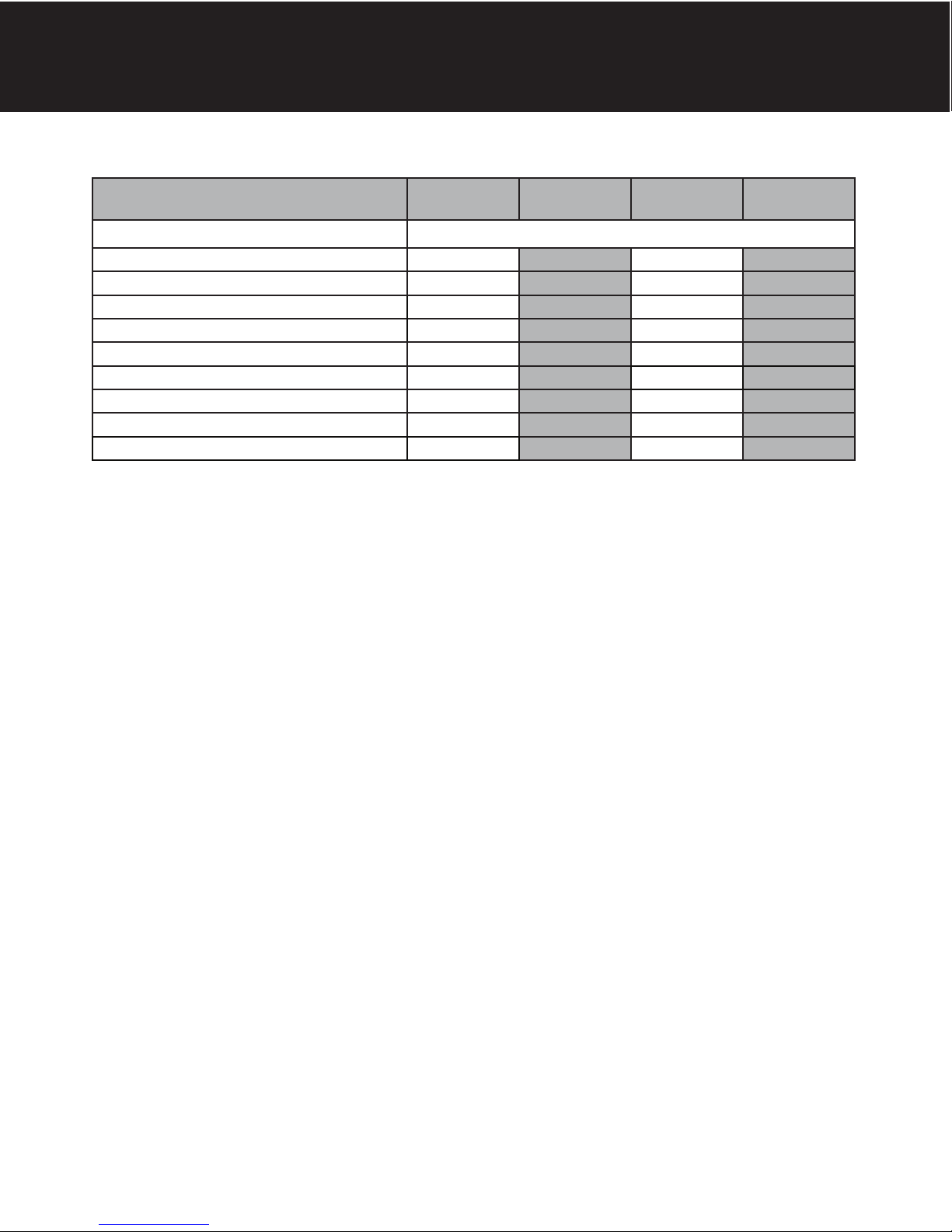
General Specifications
Filter Media Type
Filter Media Capacity (cu ft) 1.50 2.00 2.50 3.00
REACTR ™ Tank (polyglass) 10 x 54 10 x 54 10 x 54 16 x 40
Mineral Tank (Vortech ™) 10 x 54 12 x 52 13 x 54 13 x 65
Service Flow Rate - Continuous (gpm) 5 6 8 9
Service Flow Rate - Intermittent (gpm) 7 8 10 11
Backwash Flow Rate (gpm) 5.0 6.0 7.0 7.0
Gallons Used / Backwash 100 120 140 140
Space Required - Filter Tank 10 x 10 x 62 10 x 10 x 62 10 x 10 x 62 16 x 16 x 73
Approximate Shipping Weight (lbs) 175 246 280 321
Note: Caution should always be used in sizing filters. Always choose a unit by satisifying the Backwash Requirement. Use of a flow control in the Service
Line is highly recommended. Consult the factory or your field sales person with questions. Oxyclean can be added to any existing Reactr or Reactr VS system.
RF15VS-S2
RF15VS-S3
-How the Reactr VS Works_
RF20VS-S2
RF20VS-S3
SmartBlend ™
RF25VS-S2
RF25VS-S3
RF30VS-S2
RF30VS-S3
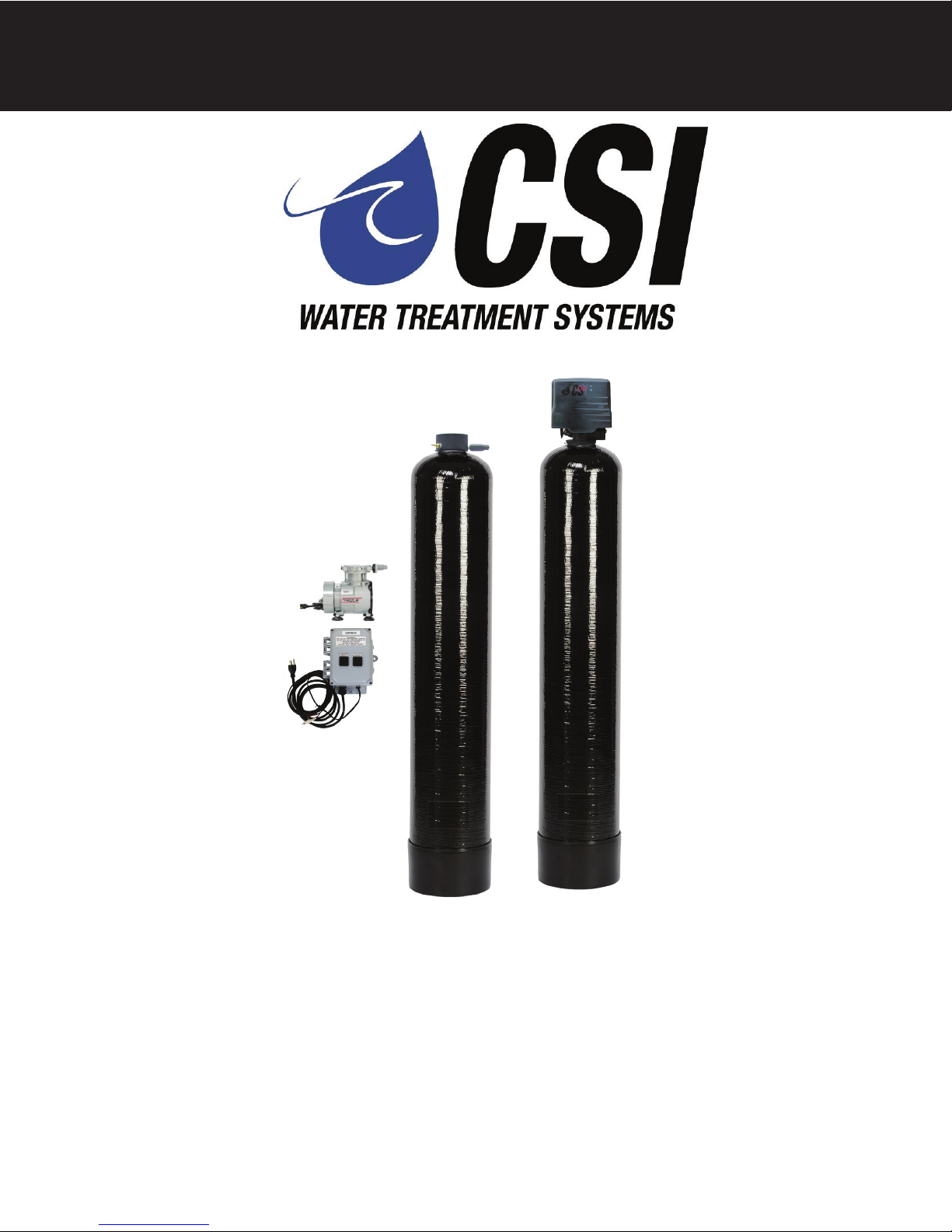
The Reactr VS requires no chemicals for its operation. It consists of two components: (1) AP tank with air compressor and
(2) filter tank. The first item serves to oxidize and precipitate iron and sulfur so that the filter can later remove them. The
water flows down through the mineral bed of the filter and out the service lines. The collected precipitates must be regularly removed from the filter by reversing the flow of water through the filter running to drain. Called “backwashing” and
lasting 10 minutes, the process expands the mineral freeing the iron, sulfur, manganese and turbidity, which are washed
out of the filter to the drain. It is important that the correct amount of water is available for the Backwash Cycle. Check
pumping capacity to be certain water is available in sufficient volume to adequately backwash the equipment at the specified rate.
WARNING
Lubricants
Do NOT use Vaseline, oils, hydrocarbon lubricants or spray silicone anywhere! Petroleum base lubricants will cause
swelling of o-rings and seals. The use of other lubricants may attack plastic Noryl®. It is recommended that Dow Corning® silicone grease be used as a lubricant for all control valves. Dow Corning® 7 Release Compound is used in the
manufacture of Chandler Systems control valves. (Part # LT-150)
Sealants
Pipe dope and liquid thread sealers may contain a carrier that attacks some plastic materials. It is recommended that
Teflon® tape be used to seal plastic Noryl® threaded fittings.
3
Page 4
Installation
-Installation Requirements-
A/P Tank
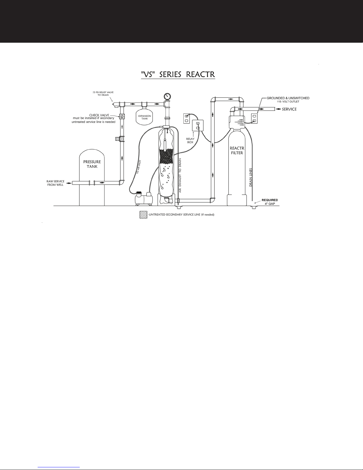
• A level floor position between the well pump and pressure tank. (See Typical Installation Diagram.)
• DO NOT install in an area of direct sunlight or where freezing temperatures may occur!
Filter Tank
• A level floor position ahead of piping into water heater.
• Unit must be installed at least 10’ ahead of the inlet to a water heater to prevent damage due to back-up of hot water.
• DO NOT install the unit in an area of direct sunlight or where freezing temperatures may occur! (See Typical
Installation Diagram.)
Relay Box
• Locate relay box near the filter tank and an unswitched 120v / 60 Hz grounded outlet
Note: If household plumbing is galvanized and you intend to make an installation with copper or vice versa, obtain
dielectric unions to prevent dissimilar metal corrosion.
Where the drain line is elevated above the control valve or exceeds 20 ft. in length to reach the drain, use 3/4 in.
I.D. drain line tubing instead of 1/2 in.
When sweat soldering copper pipe, remember to always use lead free solder and flux. Cover yoke and bypass
valve with wet rags to prevent heat damage to connections and control valve. If using PVC or plastic pipe, primers
and solvent cements specifically recommended for use for potable water are required.
Always Follow Local Plumbing Codes.
• All plumbing lines not requiring treated water should be connected upstream of the Provectr Plus tank.
4
Page 5

-Reactr VS Location / Other Requirements-
• Locate the filter near a 120 volt / 60 Hz grounded electrical outlet.
• Check for distance and proper drain installation (e.g. floor drain, washing machine standpipe).
• Determine type and size of piping required for Reactr VS connection (e.g. galvanized, PVC plastic).
Note: If household plumbing is galvanized and you intend to make an installation with copper (or vice versa), obtain
di-electric unions to prevent dissimilar metal corrosion.
Note: Where the drain line is elevated above the control valve or exceeds 20' in length to reach the drain, use 3/4" I.D.
drain line tubing instead of 1/2" I.D. Drain line tubing is not included.
Caution: When sweat soldering copper pipe (remember to always use lead free solder and flux), bypass valve with wet
rags to prevent heat damage to connections and control valve! If using PVC or plastic pipe, primers and solvent
cements specifically recommended for use with potable water are required.
Note: All plumbing lines not requiring “filtered” water should be connected “upstream” of the A/P Tank.
(See Typical Installation Diagram.)
-Installation Procedure-
Installation
1. Position Reactr VS tank and Filter tank at the desired location. The Reactr VS tank must be installed between the
pump / pressure tank and filter tank. If a water softener is to be installed, it should be positioned after the filter tank.
2. The filter media is shipped separately from the filter tank and should be loaded prior to installation.
a) Remove control valve by unscrewing it from the filter tank.
b) Plug distributor with cap provided to prevent any media from entering the inside of the tube.
c) Place media funnel onto tank and fill tank 1/3 with water
d) Pour in media. Never fill tank more than 2/3 full to allow room for backwash. Since the Reactr VS comes
with a Vortech tank, gravel is NOT needed.
e) Remove cap and replace control valve.
3. Turn off main water supply and open nearest faucet to relieve pressure.
4. Cut main line and install the AP tank and Filter tank.
5. Turn on main water supply and allow water to flow through new plumbing and keep the nearest faucet open to
evacuate air.
6. Check for leaks.
7. If no leaks, proceed by slowly opening the bypass and allow water to fill the filter tank.
8. Allow water to run through the filter for a few minutes and then turn off the nearest faucet.
Caution: Raised arrows located on the sides of control valve body and bypass valve indicate proper direction of
water flow. Install inlet and outlet piping in direction of arrows. It is recommended that a vacuum breaker be
installed on the inlet plumbing.
- Air Compressor / Relay Box –
• Locate the air compressor in close proximity to the AP tank assembly.
• Connect the supplied tubing to the compressor and the other end to the AP tank manifold insert.
• Insert the compressor’s electrical plug into the relay box.
• Insert the electrical plug from the relay box to an unswitched 120v / 60Hz grounded outlet.
• Attached by the relay box is a red and white RCA cable which plugs into the “B” (RED) and “S” (WHITE)outputs of the
control valve.
Note: As water flows through the filter, the meter will turn and send a signal to the relay box and the relay box will
turn on the air compressor. Make sure air compressor switch is turned on.
5
Page 6
Installation
- Drain Line Connection -
1. The drain line flow control assembly is pre-assembled for your convenience. Should you choose to hard plumb the
drain line, please remove the barb fitting. The flow control housing can be removed by removing the clip and pulling
straight out on housing.
Note: When re-installing the drain line flow control housing, be sure you hear and feel the O-Ring pop into place before
inserting the clip.
2. Install 1/2” I.D. drain line tubing (not included) from hose elbow to an open drain. A 4” gap between end of the drain line
and the open drain is required to prevent waste water backflow. Keep the drain line as short as possible. An overhead
drain line can be used if necessary, but should discharge below the control valve. A syphon trap (taped loop) at the
outlet of the drain line is advisable to keep the drain line full and assure correct flow during backwash. Elbows or other
fittings must be kept at a bare minimum.
Note: Where the drain line is elevated above the control valve or exceeds 20 feet in length, 3/4” I.D. drain line tubing
should be used.
- Electrical Connection -
1. Connect the power supply to the control valve and plug into a 115 volt / 60 Hz receptacle.
Note: Do not plug into an outlet controlled by a wall switch or pull chain that could inadvertently be turned off.
Electronic Connections
P - Power Supply
P B S
B - Powered in Backwash Step Only
(Cycle #1)
S - Powered based on Water Flow During
Service & Powered Backwash Cycle
- Pressurizing The System -
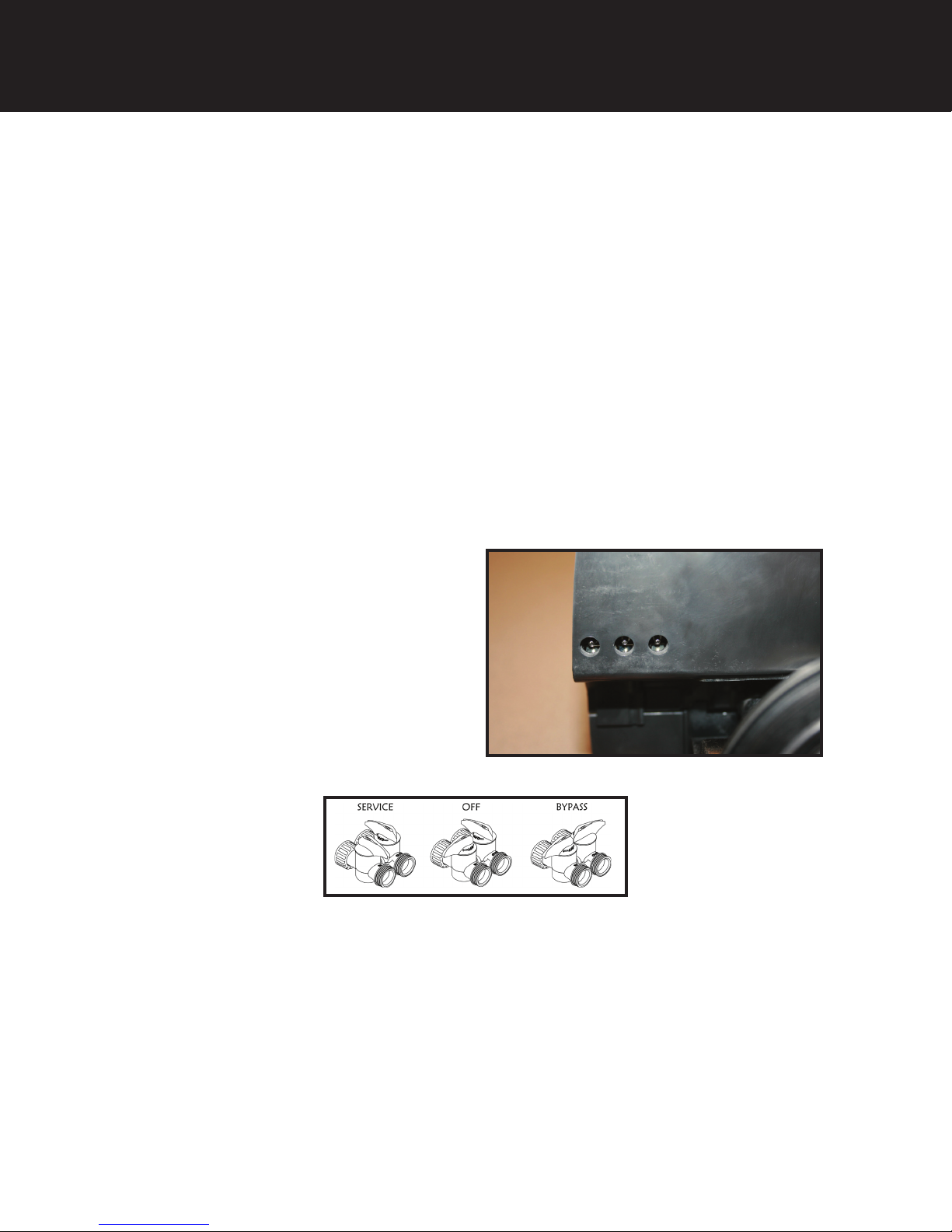
2. Slowly rotate handle of the bypass valve to the SERVICE position.
3. Open the nearest faucet to evacuate air from plumbing lines.
4. Check for leaks! If water is observed leaking from bypass, o-rings on valve body may not be seated properly. Exercise
bypass valve.
5. After air is evacuated from plumbing lines, turn off faucet.
1. Advance control valve to BACKWASH (cycle 1) position and allow water to run to drain for 3 to 4 minutes.
Warning: Close handle on bypass prior to selecting the backwash position. After backwash position has been
established, slightly open valve on bypass to evacuate air from the media tank. Fully open bypass valve
when all air is depleted. This procedure will prevent media form being uplifted into control valve.
2. Advance control valve to RAPID RINSE (cycle 3) position and allow water to run to drain for 3 to 4 minutes.
3. Advance control valve to SERVICE (cycle 0) position.
6
- Initial Control Valve Operation -
Page 7
- Final Checkout -
1. Be certain that the bypass valve is in Service position and main valve is completely on.
2. Check electrical supply to be certain the cord is connected to an uninterrupted 115 volt outlet.
3. Be certain to REGISTER YOUR PRODUCT online at www.csiwater.com
4. Leave this manual with the homeowner.
Important Notice - The plumbing system, piping, pressure tank, hot water tanks, softeners, etc. that have been exposed
to iron bearing water may need to be cleaned of the precipitated iron that has been collected in them or iron bleed thru
may be a problem. We suggest all tanks be drained and flushed thoroughly.
- Programming The Control Valve -
1. Set time of day.
2. Set a.m. or p.m.
3. Set number of days between backwash. (This generally will be every 4 to 6 days.)
1. Set regeneration time if other than 12:00 a.m. is desired.
Main Menu
Control Start-Up Procedures
12:00
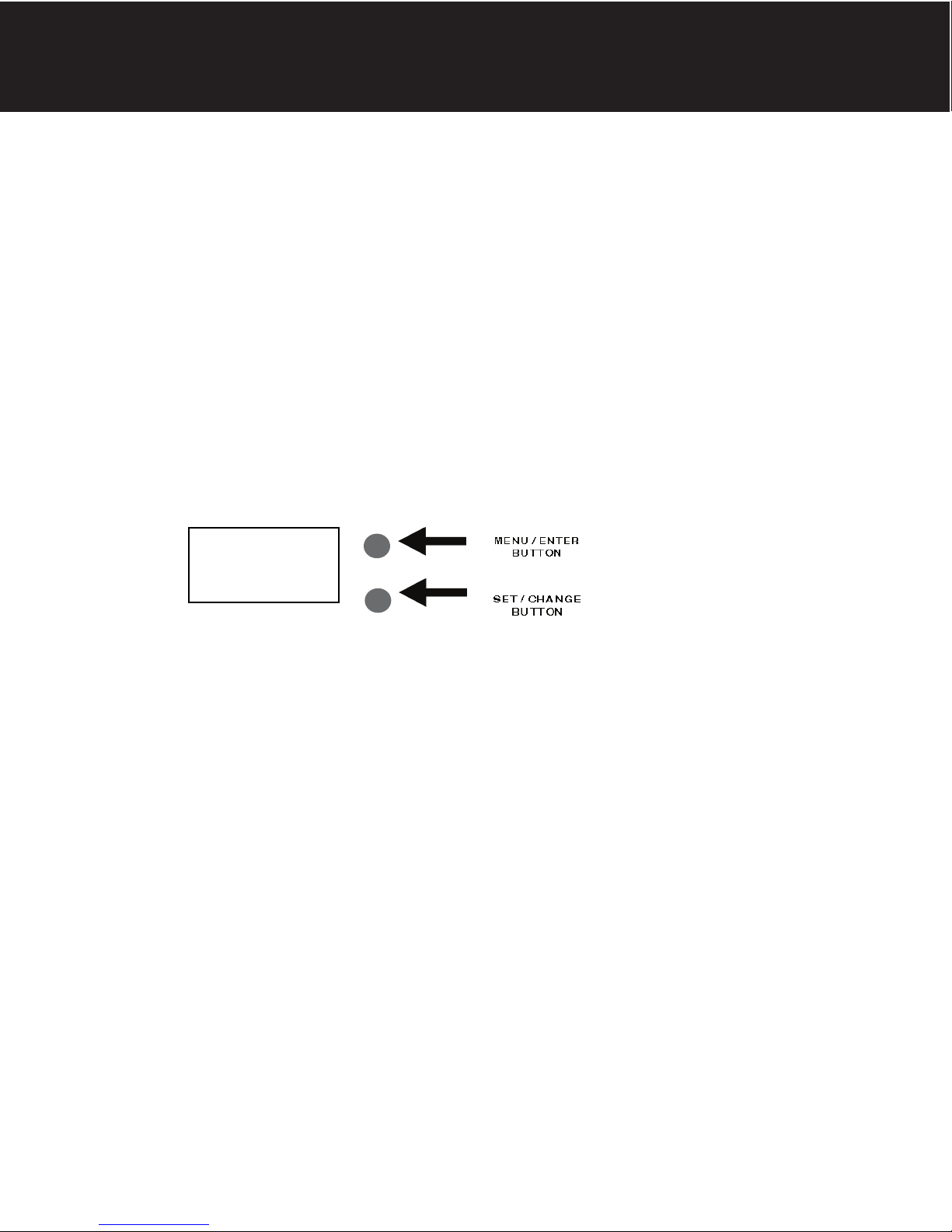
1. To enter Main Menu, press the Menu/Enter button.
(Time of Day will flash)
2. To set the Time of Day, press the Set/Change button.
(First digit will flash) Example (12:00) To change digit value, press the Set/Change button.
- To accept the digit value, press the Menu/Enter button.
- Next digit will flash to begin setting.
- Once the last digit display is accepted, all digits will flash.
3. To set A.M. or P.M., press the Menu/Enter button.
- To change digit value, press the Set/Change button. Example ( A )
- To accept the digit value, press the Menu/Enter button.
- Once A.M. or P.M. is accepted, the next menu item will flash.
4. a. To set the Number of Days between Backwash Cycles (A), press the Set/Change button. Repeat instructions from step (2). Example ( A - 06 )
Notes: 1) Maximum value is 29.
2) If value set to 0, Automatic Backwash will never occur.
3) Default setting is 6 days for filters.
5. To Exit Main Menu, press the Menu/Enter button.
Note: If no buttons are pressed for 60 seconds, the Main Menu will be exited automatically.
7
Page 8
Control Start-Up Procedures
Normal Operation
1. Home Display
a. Alternates between the display of Time of Day and Number of Days until the Next Backwash. (Metered
Softeners will alternate between time of days and gallons remaining until next regeneration)
- Days Remaining until the Next Backwash will count down from the entered
value until it reaches 1 day remaining.
- A Backwash Cycle will then be initiated at the next designated regeneration time.
2. Battery Back-Up (Uses a standard 9-volt alkaline battery.)
Features of Battery Back-Up:
• During power failures, the battery will maintain the time of day as long as the
battery has power. The display is turned off to conserve battery power during
this time. To confirm that the battery is working, press either button and the
display will turn on for five (5) seconds.
• If power failure occurs while system is regenerating, the Isobar 2 will motor to a shut off position
to prevent constant flow to drain. Depending upon system pressure and other factors, it is
possible to observe a reduced flow to drain during this step. After power is restored, the Isobar
2 will return and finish the cycle where it left off prior to the power interruption.
• When used without battery back-up, during a power failure, the unit stops at its current point in
the regeneration position and then restarts at that point when the power is restored. The time
will be offset by the increment of time the unit was without power, so it is necessary to reset the
time of day on the unit. No other system will be affected.
Starting Extra Regeneration Cycle
1. To Start Delayed Extra Cycle Example ( 1 ) -
If Days Remaining Until Next Backwash does not read ‘1’, press and hold the
Set/Change button for 3 seconds until the display reads ‘1’.
- Backwash cycle will initiate at the next designated backwash time.
2. To start Immediate Extra Cycle First complete above step.
- With Days Remaining Until Next Regeneration at ‘1’.
- Press and hold the Set/Change button.
- After 3 seconds, the backwash cycle will begin.
3. To Fast Cycle thru regeneration First complete above 2 steps.
Note: Press and hold the Set/Change button for 3 seconds to advance to the next cycle step.
Fast Cycle is not necessary unless desired to manually step through each cycle step.
(Repeat until valve returns to the home display)
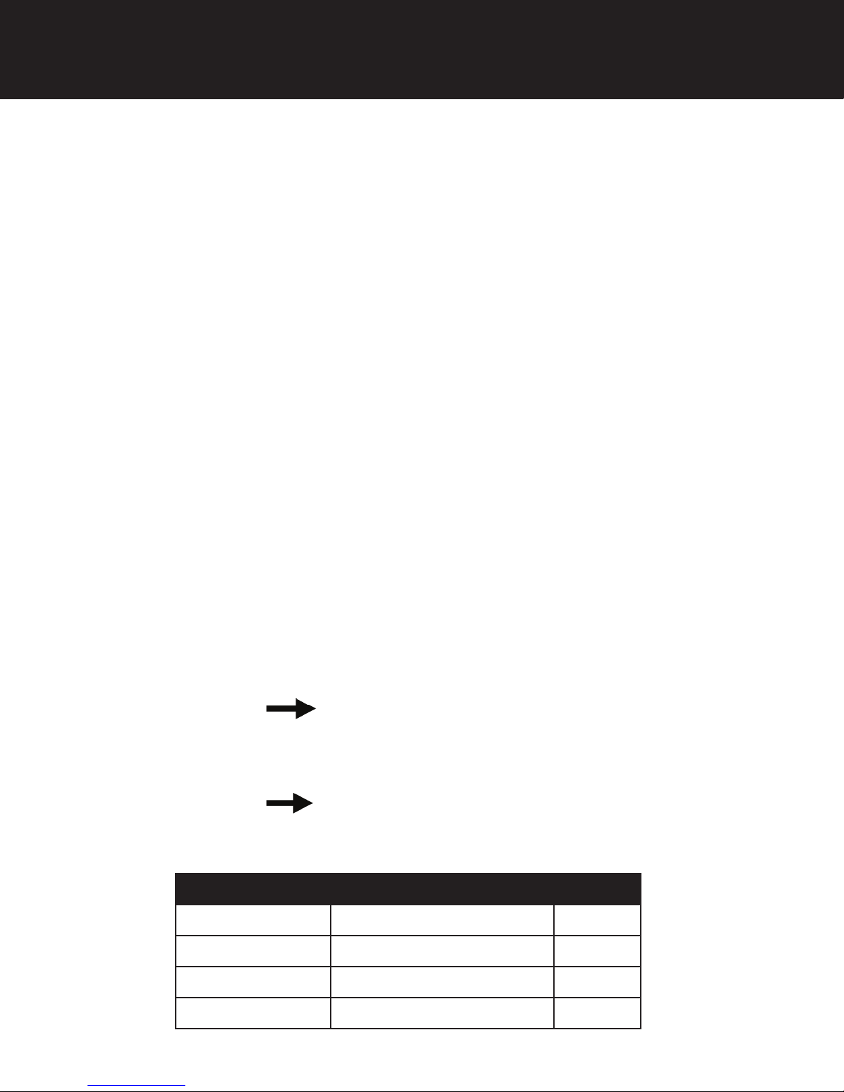
Filters Default (Min)
Step 1 Backwash 10
Step 2 Rest 5
Step 3 Rapid Rinse 10
Step 4 Not Used 0
8
Page 9
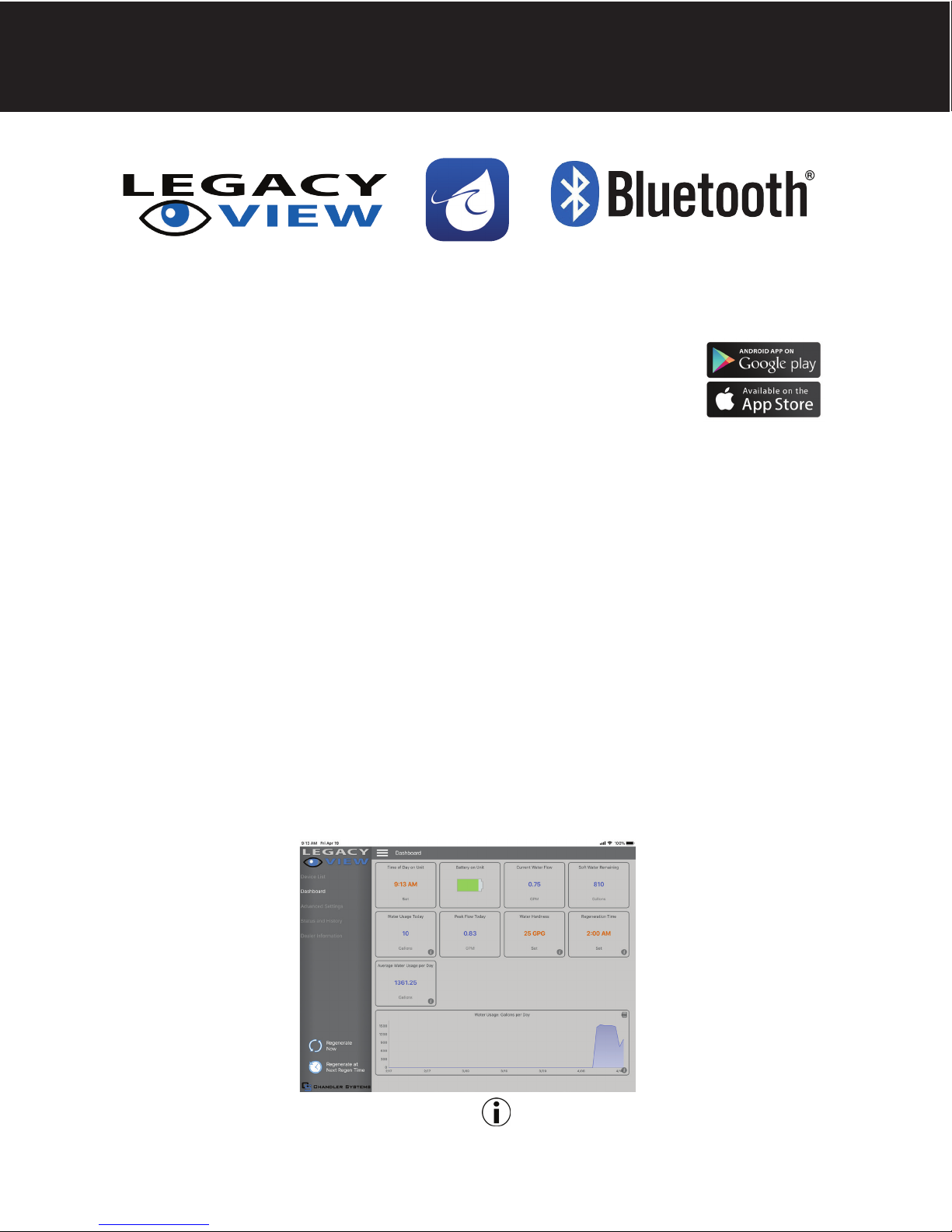
For simplified set up and control, please install the Legacy View on a compatible Bluetooth 4.0+ enabled smart phone or
tablet.
1. Download and install the Legacy View app from the Google Play Store, Apple App Store
2. Open the Legacy View app
• Choose a valve device at any time from the list of available devices to connect to by clicking on it.
• If the valve you want to connect to doesn’t show up, or there is a problem connecting to a device you can
press the “Scan for Devices” button or the Legacy View logo at any time to refresh the list and start the
process over.
• If the valve device is a BTLE valve and it has a password other than the default password, the first time you
connect to it the app will ask you to enter the password. After entering it the first time you should not need to
enter it again unless it changes.
3. BTLE Valve devices can be updated by the App. When the app is updated from the Google Play Store or the Apple
App Store, it may contain an updated firmware program for the valve devices. These updates could contain new
features or operational improvements. It is up to the user to allow these updates to be sent to the valve device.
Uploading a new program takes approximately 1 minute.
Utilizing Bluetooth Control
Dashboard
NOTE: Consult your dealer before making any changes
From the Dashboard, all items in ORANGE can be changed, while blue fields are informational only.
If you are unsure about the function of the field click the for more information.
9
Page 10
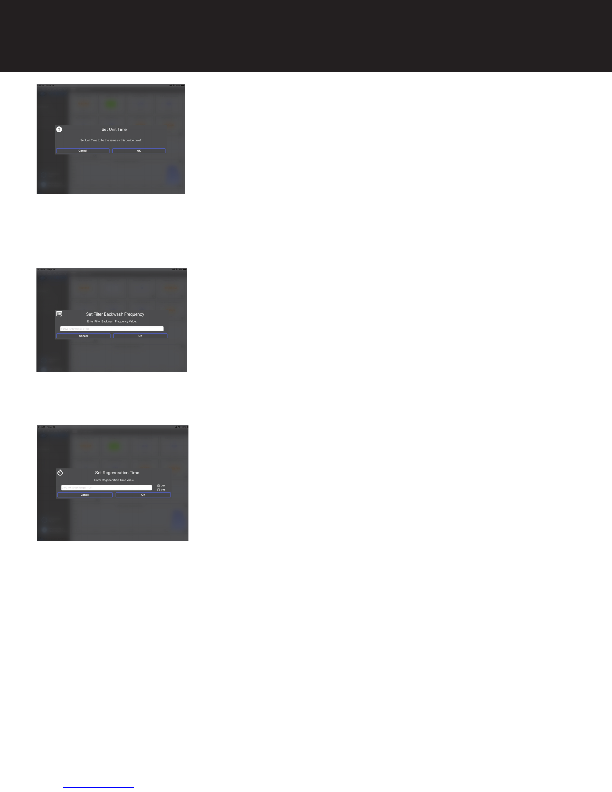
Set Up Utilizing Bluetooth App
Change Time of Day (Press “SET” to set time automatically based on device).
For Filters:
Set Backwash Frequency
This sets the amount of day between backwash cycles
Set Regeneration Time
Example: For 2a.m., just type 2, choose a.m., and press ‘OK’
Note: If you have a filter and a softener the valves should be set to regenerate
at different times. Factory default times are 12a.m. for filters, and 2 a.m. for
softeners.
Advanced Settings
NOTE: Consult your dealer before making any changes. We do not recommend changing Advanced Settings unless you
have a good understanding of the system operation.
From the Advanced Settings, all items in ORANGE with a “set” button can be changed.
10
Page 11
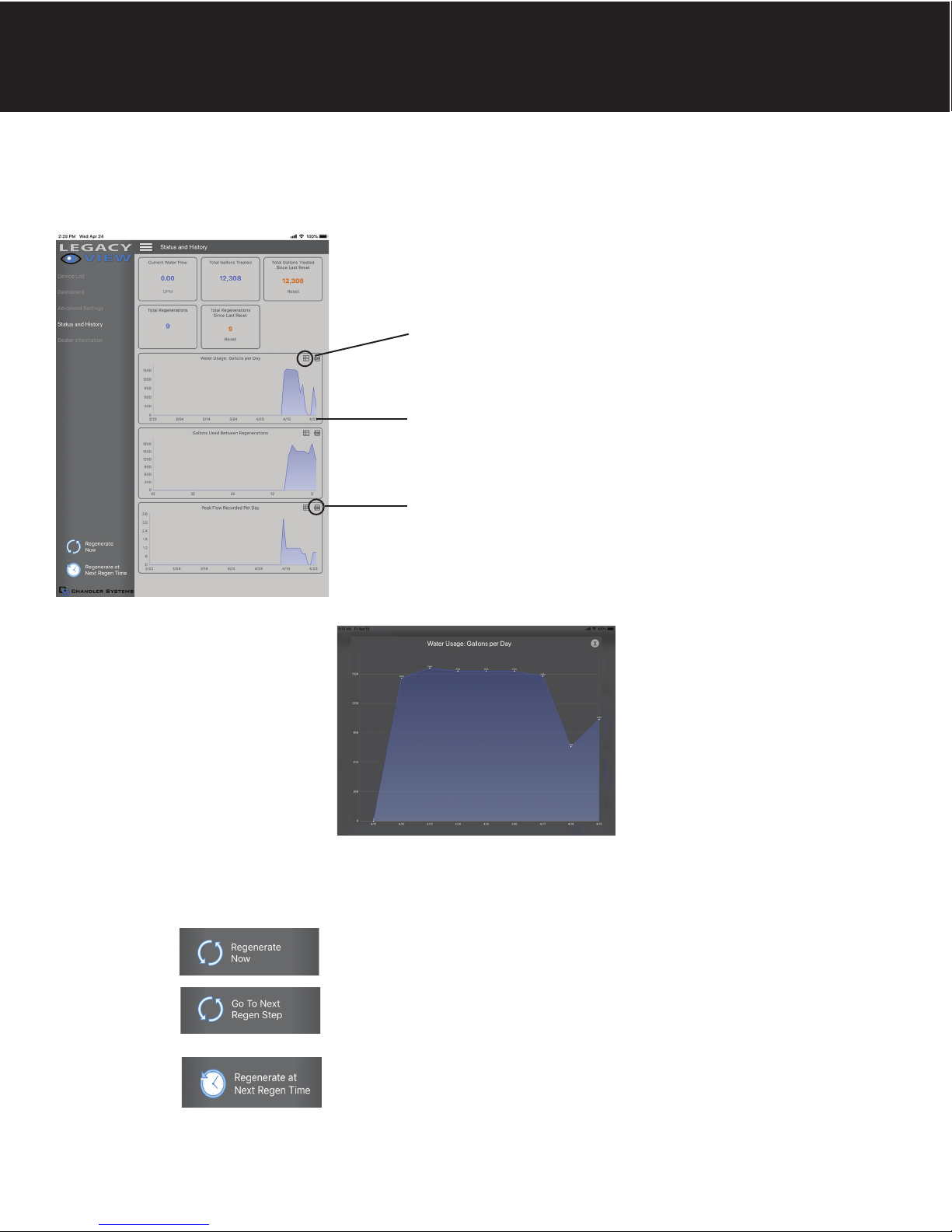
Set Up Utilizing Bluetooth App
Status and History
From the Status and History, all items in ORANGE can be reset.
Pressing this icon will show a list of
the data that is in the graph
Touch any graph to enlarge and see
details. Enlarged graphs are able to
be zoomed in by pinching with two
fingers.
(Enlarged graph shown below)
Pressing the .csv logo in the corner
will allow the graph data to be
exported and shared.
1. Start a regeneration or backwash cycle
Option 1: Click the “Regenerate Unit Now.”
Option 2:
Enlarged graph showing water usage
Once a regeneration has been started, if you would like to force the unit into the
next cycle step click “Go to Next Regeneration Step”.
“Regenerate Unit at Next Regen Time” button
This will take the system into a backwash cycle at the next regeneration time.
11
Page 12

Master Programming Mode
Master Programming Mode
To enter Master Programming Mode, press and hold both buttons for 5 seconds.
Note: All Master Programming functions have been preset at the factory. Unless a change is desired, it is NOT
necessary to enter Master Programming Mode.
1. Regeneration Time ( r ) Example ( r 12A )
- The time of day at which backwash may take place is designated by the letter “r”.
- Default regeneration time settings is 12a
- The first display digit indicates A.M. or P.M. To change the value, press the Set/Change button.
- Press Menu/Enter button to accept the value and move to the next digit.
- The second and third display digits indicate the hour at which the backwash will occur.
- Change the digits with the Set/Change button and accept with the Menu/Enter button.
- After the entire display flashes, press the Menu/Enter button to move to the next menu item.
2. Regeneration Cycle Step Times (Steps 1, 2, 3, 4)
Example ( 3 - 10)
- The next 4 displays set the duration of time in minutes for each backwash cycle step.
- The step number which is currently modifiable is indicated on the far left of the display screen.
- The number of minutes allotted for the selected backwash step is displayed on the far right.
- Change the digit values using the Set/Change and Menu/Enter buttons as described above.
3. Bluetooth Enabled BE - 1 (ON)
BE - 0 (OFF)
4. Bluetooth Password BBPP is displayed for one second, then password is displayed.
5. To Exit the Master Programming Mode, press the Menu/Enter button until time of day returns.
Note: If no buttons are pressed for 60 seconds, the Master Programming Mode will be exited automatically.
12
Page 13
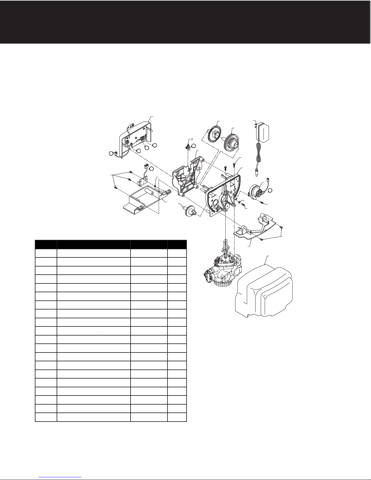
Control Valve Assembly - Signature 2 & SIGNATURE 3
1
M
P
E
13
LETTERS IN DIAGRAM REPRESENT WIRING CONNECTIONS
* "F" Port is for softener flow meter connection (flow meter not shown)
F
P
16
8
19
Ref Description Part Number Qty
0 Power Head Assy. 21006X100 1
1 Filter Circuit Boad Assy. 21002X101 1
2 Encoder 20001X124 1
3 Front Plate 20001X004 1
4 Encoder Wheel 20001X007 1
5 Main Gear 21001X120 1
6 Power Supply 20001X125 1
7 Back Plate 20001X005 1
8 Lower Front Base For Cover 20111X002 1
9 Motor 20016X006 1
10 Lower Back Base for Cover 20111X003 1
11 Valve Cover 20111X000 1
12 Piston Screw 20001X003 1
13 Screw SC10 3
14 Screw SC9 2
15 Piston Washer 20001X002 1
16 Washer Circuit Board 20111X014 1
17 Screw Motor SC2 1
21 Valve Hex Screw 20001X001 2
N/S Meter Assy. 20003X200 1
4
E
3
6
5
18
7
9
M
15
12
10
17
14
11
13
Page 14
2
4
5
6
7
1
3
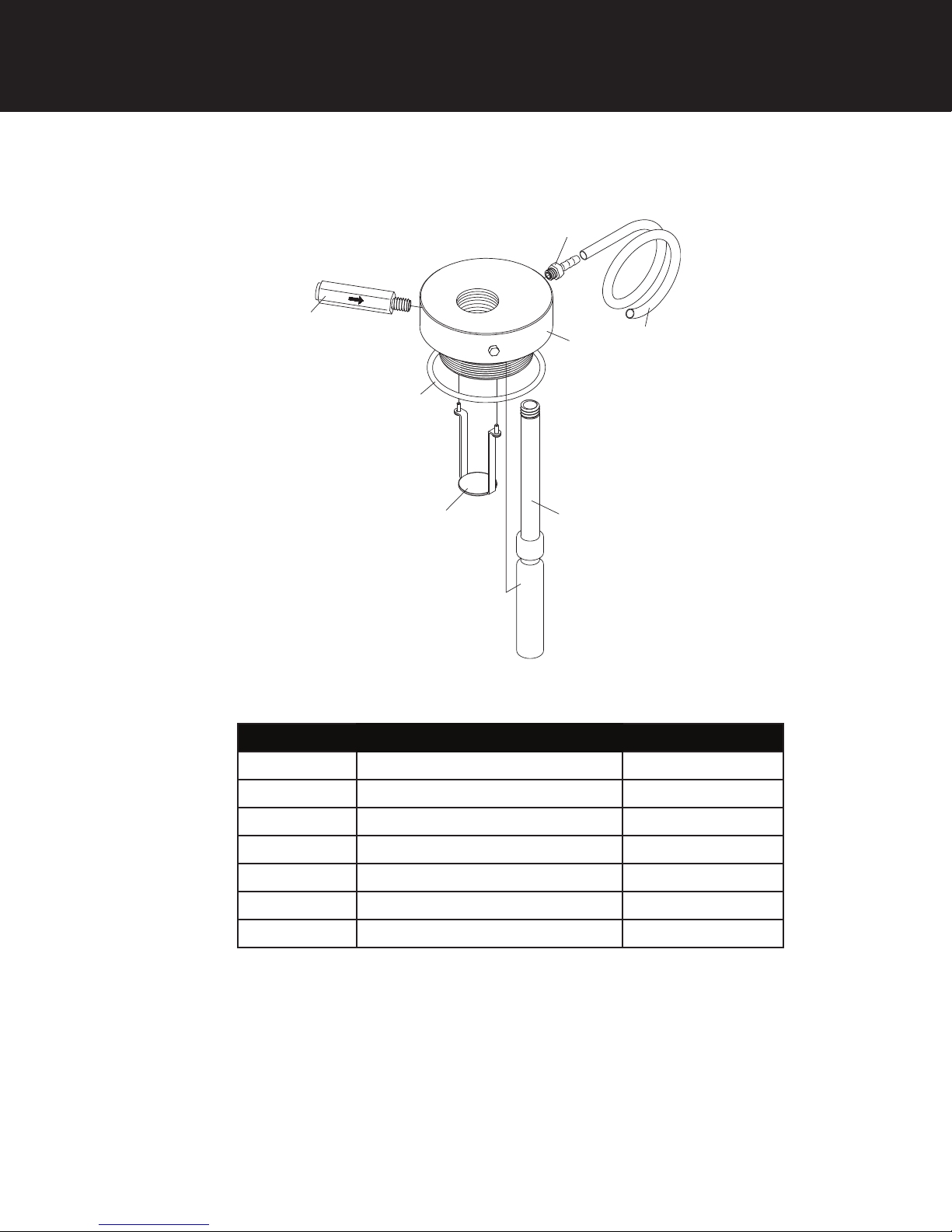
Manifold - Signature 2 & SIGNATURE 3
Ref Description Part Number
1 1/4” Brass Hose Barb 65555X217
2 Vent Tube 3/4” OD X 1/4” ID X 12” 65555X216
3 VS Manifold with O-Ring 65555C007
4 Reactr Float Assembly 65555X210
5 Diffuser with Screws 65555X212
6 Manifold O-Ring 20561X205
7 VS Check with 1/4” Tube X 1/4” NPT 68555X215
14
Page 15
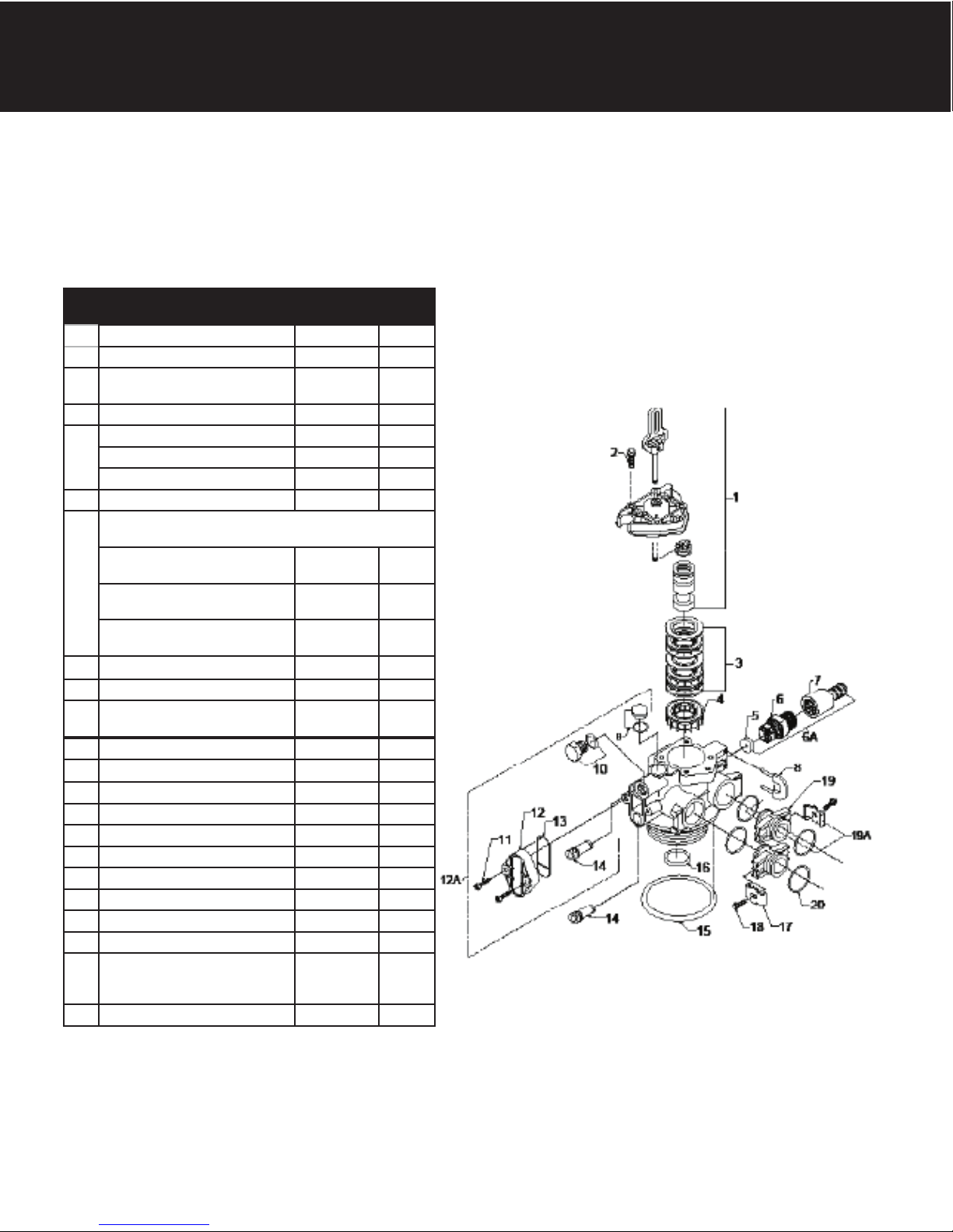
Valve Body Assembly - Signature 2
Ref
#
1 Piston Assembly 20001X231 1
2 10-24 X 13/16” Screw 20001X226 3
3 Seal and Spacer Kit Incl (5) #3
& (4) #4
4 End Spacer N/S 1
5 Flow Control Button 5.0 GPM 20251X272 1
Flow Control Button 6.0 GPM 20251X274 1
Flow Control Button 7.0 GPM 20251X273 1
6 Plastic Flow Control Housing 20017X100 1
6A Flow Control Assembly-Specify GPM
Incl. (1) each #5, #6, #7
Flow Control Assy. 5.0 GPMPVC
Flow Control Assy. 6.0 GPMPVC
Flow Control Assy. 7.0 GPMPVC
7 Drain Line Hose Barb 20017X235 1
8 Drain Retainer 20017X214 1
9 O Ring & Brine Valve Cap
Assembly
10 O Ring & Filter Plug Assembly 20001X229 1
11 10-24 X 1 Screw 20001X226
12 Injector Cap 20001X223 1
13 Injector Seal 20001X224 1
14 Injector Plug & O Ring Assembly 20001X217 1
15 Valve O Ring 20561X205 1
16 Dist O Ring 20561X204 1
17 Mounting Clip 20561X201 2
18 8-18 X 5/8” Screw 20561X217 2
19 Adapter Coupling N/S 2
19A Adapter Coupling & O Ring
Assembly Incl. (1) # 17, #18, #19
& (2) #20
20 O Ring 20561X216 4
Description Part # Qty.
20561X253 1
20017X262 1
20017X263 1
20017X264 1
20001X230 1
20561X215 1
1
15
Page 16
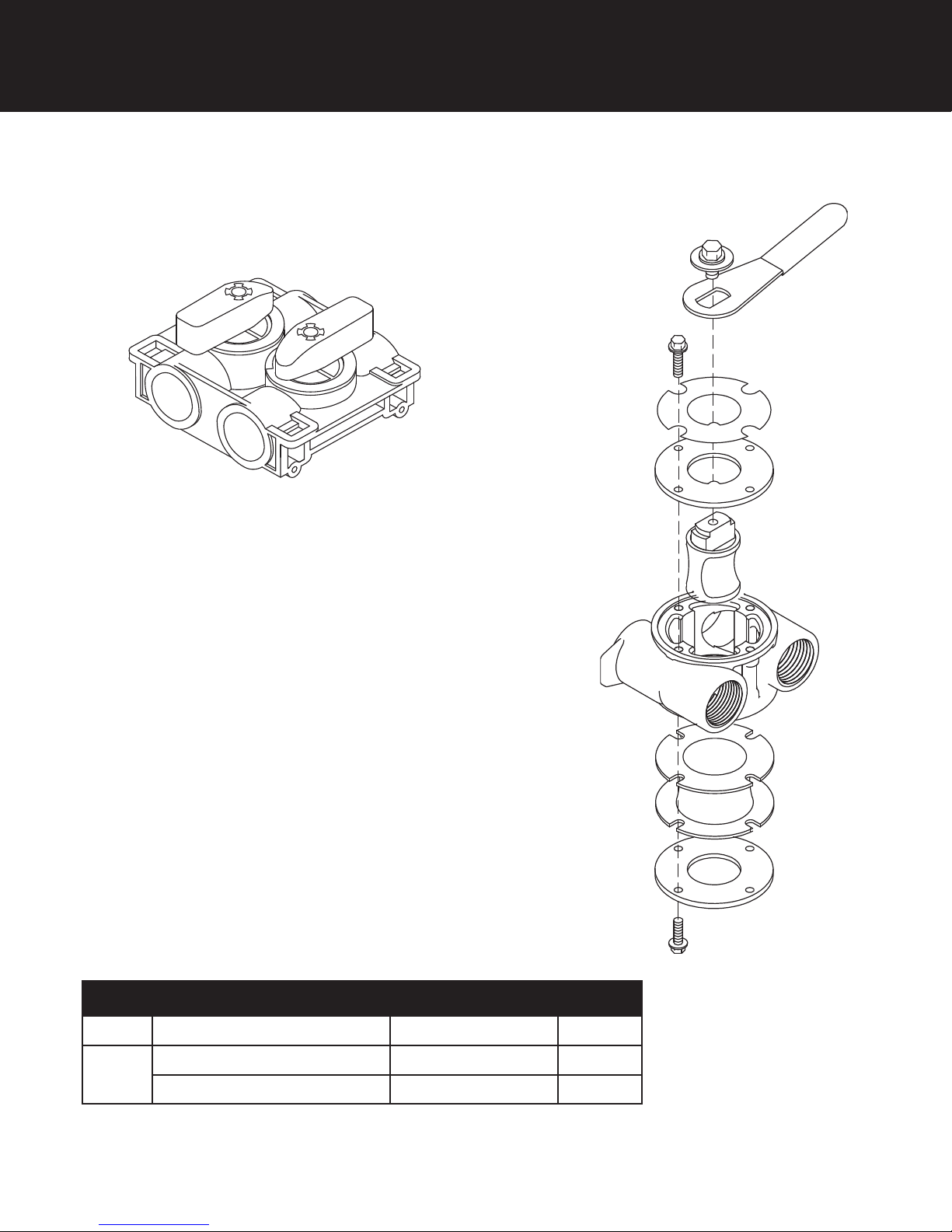
Bypass Assembly - Signature 2
(1)
(2)
Ref # Description Part # Qty
Plastic Bypass Valve Assembly 20561X292
1
Bypass Valve 3/4” Stainless Steel 20561X270
2
Bypass Valve 1” Stainless Steel 20561X283
16
1
1
1
Page 17
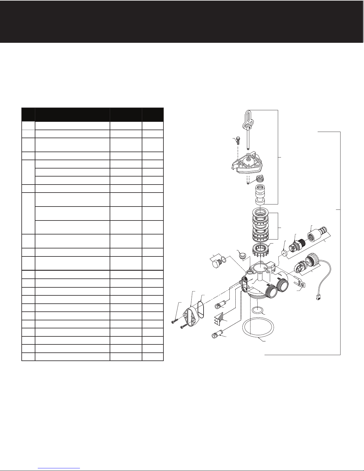
Valve Body Assembly - SIGNATURE 3
Ref
#
1 Piston Assembly 20001X231 1
2 10-24 X 13/16” Screw 20001X226 3
3 Seal and Spacer Kit Incl (5) #3
& (4) #4
4 End Spacer N/S 1
5 Flow Control Button 5.0 GPM 20251X272 1
Flow Control Button 6.0 GPM 20251X274 1
Flow Control Button 7.0 GPM 20251X273 1
6 Plastic Flow Control Housing 20017X100 1
6A Flow Control Assy. 5.0 GPM-
PVC
Flow Control Assy. 6.0 GPMPVC
Flow Control Assy. 7.0 GPMPVC
7 Drain Flow Fitting 1/2” NPT X
1/2”
8 Drain Retainer 20017X254 1
9 O Ring & Brine Valve Cap
Assembly
10 O Ring & Filter Plug Assembly 20001X229 1
11 10-24 X 1 Screw 20001X226
12 Injector Cap 20001X223 1
13 Injector Seal 20001X224 1
14 Injector Plug & O Ring Assembly 20001X217 1
15 Screen 20001X222 1
16 Plug 20001X217 1
17 Valve O-Ring 20561X205 1
18 Dist. O-Ring 20561X204 1
19 Meter Assembly 20017X203 1
20 Valve Body Assembly VH2-B-D15 1
Description Part # Qty.
20561X253 1
20017X262 1
20017X263 1
20017X264 1
20017X255 1
20001X230 1
2
1
20/21
3
7
6
5
10
4
9
6A
19
1
12
13
8
11
14
18
15
16
17
17
Page 18
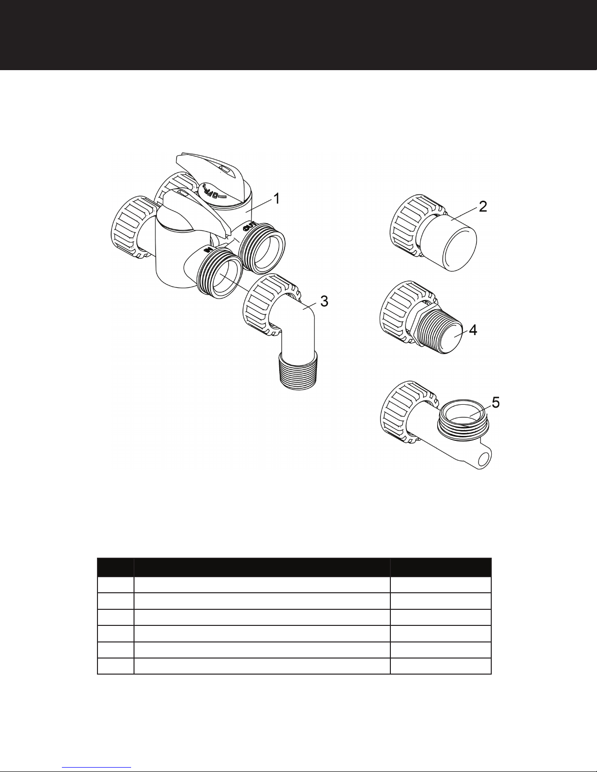
Bypass Assembly - Signature 3
Ref Description Part No.
1 D15 Bypass 20017X283
2 1” Female Straight Slip Set (optional) 20017X288
3 1” NPT Elbow Set 20017X284
4 1” NPT Straight Set 20017X289
5a Elbow, Vertical Adapter Blank (optional) 20017X295
5b Elbow, Vertical Adapter 1/4” NPT Tapped (optional) 20017X294
18
Page 19

Service Instructions / Instructional Videos Available at www.csiwater.com
A. General Preliminary Instructions
PERFORM BEFORE ALL SERVICING OPERATIONS
1. Turn off water supply to conditioner.
-If the conditioner installation has a “three valve” bypass system, first open the valve in the bypass line, then
close the valves at the conditioner inlet and outlet.
-If the conditioner has an integral bypass valve, put it in the bypass position.
-If there is only a shut off valve near the conditioner inlet, close it.
2. Remove cover and relieve water pressure in the conditioner by stepping the control into the backwash
position momentarily. Return the control to the service position.
3. Unplug electrical cord from outlet.
B. To Replace Powerhead
1. Remove the control valve cover and disconnect the power supply.
2. Disconnect the meter cable from circuit board and feed back through control (if existing meter is being re-used)
3. Remove lower back base screws and detach lower back base.
4. Remove screw and washer at drive yoke. Remove powerhead mounting screws. The entire powerhead
assembly will now lift off easily.
5. Put new powerhead on top of the valve. Be sure the drive pin on main gear engages slot in drive yoke (wide
side of drive yoke upright must face to the left away form the motor).
6. Replace powerhead mounting screws. Replace screw and washer at drive yoke.
7. Reattach lower back base.
7. Reconnect meter signal, wire and power supply.
8. Reinstall cover.
C. To Replace Piston Assembly
1. Follow steps A1 - A3
2. Disconnect the meter signal wire from the circuit board.
3. Remove lower back base screws and detach lower back base.
4. Remove screw and washer at piston drive yoke. Remove powerhead mounting screws. The entire powerhead
assembly will now lift off easily.
5. Remove piston retaining plate screws.
6. Pull upward on end of piston yoke until assembly is out of valve.
7. Inspect the inside of the valve to make sure that there is no foreign matter that would interfere with the valve
operation.
8. Install new seals and spacers.
9. Take new piston assembly and push piston into valve by means of the end plug. Twist drive yoke carefully in a
clockwise direction to properly align it with drive gear. Reinstall piston retaining plate screws.
10. Follow steps B5 - B9
D. To Replace Seals and Spacers
1. Follow steps A1 - A3.
2. Disconnect the meter signal wire from the circuit board.
3. Remove screw and washer at piston drive yoke. Remove powerhead mounting screws. The entire powerhead
assembly will now lift off easily. Remove piston retaining plate screws.
4. Pull upward on end of piston rod yoke until assembly is out of valve. Remove seals and spacers. (Note: Special
end spacer must be reused)
5. Lubricate new seals with silicone lubricant included in the seal and spacer kit. Make sure the special end
spacer is properly seated in the valve body. Install new seals and spacers individually, pressing around the
outer edge of each seal to make sure it is seated. (When all seals and spacers are seated properly, you will
have a 1/4” of space between the top seal the the top of the valve body)
6. Follow Steps C9 - C10.
19
Page 20
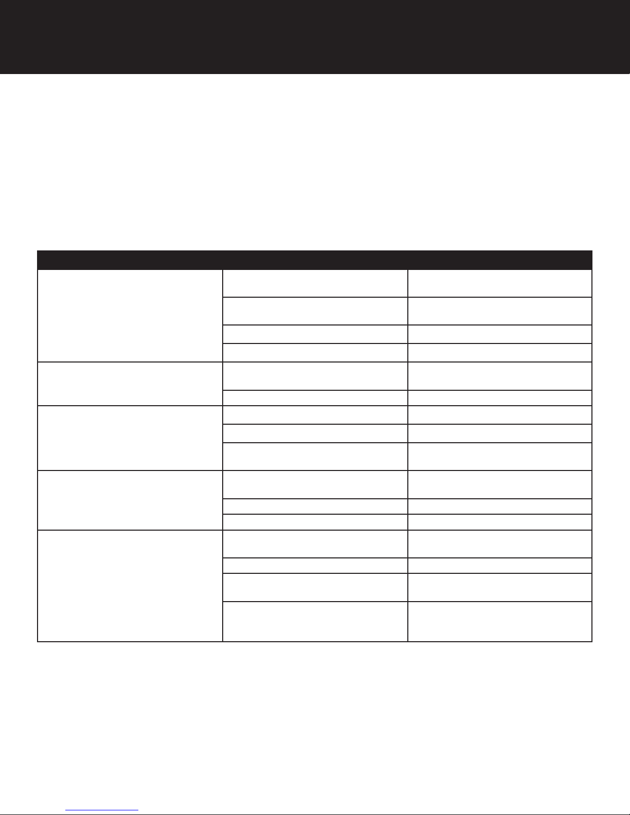
Troubleshooting Guide
E. To Replace Meter
1. Follow steps A1 - A3
2. Unplug meter cable from front of circuit board.
3. Unscrew meter assembly nut from valve body.
4. Remove meter from valve body and clean or replace as necessary.
5. Reinstall meter, nut and cable.
SYMPTOM PROBABLE CAUSE CORRECTION
Power supply plugged into
1.Filter Fails to
Regenerate
Automatically
intermittentent or dead power source
Improper control valve
programming
Defective power supply Replace power supply
Connect to constant power source
Reset program settings
2. Regeneration at
Wrong Time
4. Poor Water Quality
6. Loss of Water Pressure
7. Continuous Flow to
Drain
Defective Drive motor Replace motor
Time of day improperly set, due to
power failure
Regeneration time set improperly Reset regeneration time programming
Check items listed in #1 and #2
Bypass valve open Close bypass valve.
Channeling Check for too slow or high service
Scaling / fouling of inlet pipe Clean or replace pipeline. Pretreat to
Fouled media Clean media. Pretreat to prevent.
Improper backwash setting Backwash more frequently
Foreign material in control Call dealer. Clean valve and replace
Internal control leak Same as above.
Valve jammed in backwash, brine or
rapid rinse position
Motor stopped or jammed Check for jammed piston. Replace
Reset time of day programming and
install 9-volt battery.
flow. Check for media fouling.
prevent.
piston and seals
Same as above.
piston and seals. Replace motor if
motor is unresponsive.
20
Page 21

Control Valve Error Code Diagnosis
Under normal operating conditions, when your control valve is in the “in service” position, the display should alternate
between the current time of day and the number of days remaining (for filters and time clock softeners) or gallons
remaining (for metered softeners) until the next regeneration. This is the “home display.” If the valve is currently going
through a regeneration cycle, the display will show the cycle step on the left side of the display and the number of minutes
remaining in that step on the right side of the display. If any other information is being displayed, then the valve is
informing you of an issue. There are five error codes which could indicate an issue with the control valve. When an
error is being displayed, the valve will be in a stopped position, and the buttons will not respond to being pressed. Even
if the cause of the error code is corrected, the error code will not clear until the power supply has been disconnected and
reconnected (this will be referred to as “cycling” the power). All error codes are displayed as the letters “Err” followed by a
flashing number 2-6:
Error 2 - Valve is searching for homing slot.
Allow valve to continue running. If the homing slot is found, the valve will return to the home display, otherwise, another
error code will appear.
Error 3 - No encoder slots are being seen.
This occurs when the motor is running, but the encoder is not seeing any of the slots in the encoder wheel. This can
happen if the encoder has been disconnected, but most commonly occurs when debris in the valve body has stopped the
piston, causing the encoder wheel to be unable to turn.
1. Check encoder connection. If the encoder is plugged in and snapped into place, skip to step #2 below. If
encoder is disconnected, reconnect it and cycle power to clear the error.
2. Disconnect powerhead from valve body, cycle power to clear the error code. Manually cycle the powerhead
through the regeneration cycle steps to verify that the motor can cycle properly while the powerhead is
disconnected from the valve body. If the error 3 does not reappear, skip to step #3 below. If the error 3 does
reappear, order a board & motor kit to replace the circuit board & motor.
3. Remove piston and seals from the valve body and inspect valve body for debris. Replace the seal & spacer kit.
Inspect piston and replace piston if Teflon coating is worn
Error Codes
Error 4 - Unable to find homing slot.
1. Check encoder wheel for debris.
2. Cycle power. Valve should either find home or go to a different error code. If error 4 returns, replace
powerhead assembly.
Error 5 - Motor overload.
This occurs when the motor current is too high. This could be caused by an issue with the motor itself, but is typically
caused by friction in the valve body
1. Disconnect powerhead from valve body and cycle power to clear the error code.
2. If the error 5 returns, replace the motor. Otherwise, manually cycle the powerhead through the regeneration
cycle steps to verify that the motor can cycle properly while the powerhead is disconnected from the valve
body. Either way, proceed to the next step.
3. Remove piston and seals from the valve body and inspect valve body for debris. Replace the seal & spacer kit.
Inspect piston and replace piston if Teflon coating is worn.
Error 6 - No motor current.
This typically occurs if the motor cable has come unplugged from the circuit board. Check that the motor cable is plugged
into the circuit board and attached to the motor. If this is not the issue, the motor or circuit board may need to be replaced.
No Display
If your display is blank, there is no power going to the circuit board due to one of the following factors:
• The electrical outlet is not powered or is switched off
• The power cable has come unplugged from the circuit board
• The power supply has come unplugged from your electrical outlet
• The power supply has come unplugged from the control valve
• The power supply is not working
21
Page 22
Warranty
22
Page 23
WATER TREATMENT EQUIPMENT
This warranty cannot be transferred - it is extended only to the original
purchaser or first user of the product. by accepting and keeping this
product, you agree to all of the warranty terms and limitations of liability
described below.
Important Warning: Read carefully the CSI Water Treatment Systems
Equipment Installation, Operating and Maintenance Instructions Manual
to avoid serious personal injury and property HAZARDS and to ensure
safe and proper care of this product.
Model Numbers Covered:
Water Softeners, Media Filters and Upflow Filters
*FOR AS LONG AS YOU OWN AND LIVE IN YOUR SINGLE FAMILY
HOME, this warranty covers your water treatment equipment, if you are
the first user of this CSI Water Treatment Systems equipment and purchased it for single family home use - subject to all of the conditions, limitations and exclusions listed below. Purchasers who buy the CSI Water
Treatment Systems equipment for other purposes, and other component
parts are subject to more limited warranties and you should read all of the
terms included in this form to make sure you understand your warranty.
What is covered by this warranty?
CSI Water Treatment Systems warrants that at the time of manufacture,
the water treatment equipment shall be free from defects in material and
workmanship as follows :
Product Warranty
Residential Mineral Tank 10 Years
Proprietary Control Valves 7 Years
Other Softener / Filter Control Valves 5 Years
Brine Tank 5 Years
Residential Reverse Osmosis System 5 Years
Other Accessoreis and Parts 1 Year
Brine Tank Compoents 1 Year
REVERE Wireless Low Salt Alarm 90 Days
* This warranty does not include media and/or cartridge filter elements.
Additional Terms & Conditions
What CSI Water Treatment Systems will do if you have a covered
warranty claim CSI will at its option either make repairs to correct any
defect in material or workmanship or supply and ship either new or used
replacement parts or products. CSI will not accept any claims for labor or
other costs.
Additional Exclusions and Limitations
This warranty is non-transferable and does not cover any failure or problem unless it was caused solely by a defect in material or workmanship.
In addition, this warranty shall not apply :
• If the water treatment equipment is not correctly installed, operated,
repaired and maintained as described in the Installation, Operating &
Maintenance Instructions Manual provided with the product.
• Defects caused as a direct result of the incoming water quality
• If the tank is not the size indicated for the supply line size of the installation, as described in the manual.
• To any failure or malfunction resulting from abuse (including freezing),
improper or negligent; handling, shipping (by anyone
• If the unit has not always been operated within the factory calibrated
temperature limits, and at a water pressure not exceeding 125 psi other than CSI), storage, use, operation, accident; or alteration, lightning,
flooding or other environmental conditions;
• To any failure or malfunction resulting from failure to keep the unit
full of potable water, free to circulate at all times; and with the tank
free of damaging water sediment or scale deposits;
• This warranty does not cover labor costs, shipping charges, service
charges, delivery expenses, property damage, administrative fees or
any costs incurred by the purchaser in removing or reinstalling the
water treatment equipment.
• The warranty does not cover any claims submitted to CSI more than
30 days after expiration of the applicable warranty, and does not
apply unless prompt notice of any claim is given to an authorized CSI
Dealer or to CSI or a designated contractor is provided access to the
installation and to the water treatment equipment.
THESE WARRANTIES ARE GIVEN IN LIEU OF ALL OTHER EXPRESS
WARRANTIES. NO CSI REPRESENTATIVE OR ANY OTHER PARTY
IS AUTHORIZED TO MAKE ANY WARRANTY OTHER THAN THOSE
EXPRESSLY CONTAINED IN THIS WARRANTY AGREEMENT.
Additional Warranty Limitations
ANY IMPLIED WARRANTIES THE PURCHASER MAY HAVE, INCLUDING THE IMPLIED WARRANTIES OF MERCHANTABILITY AND
FITNESS FOR A PARTICULAR PURPOSE, SHALL NOT EXTEND BEYOND THE APPLICABLE TIME PERIODS SPECIFIED ABOVE. Some
states do not allow limitations on how long an implied warranty lasts, so
the above limitations may not apply to you.
Limitations of Remedies
The remedies contained in this warranty are the purchaser’s exclusive
remedies. In no circumstances will CSI or the seller of the product be
liable for more than, and purchaser-user’s remedies shall not exceed,
the price paid for the product. In no case shall CSI or seller be liable for
any special, incidental, contingent or consequential damages. Special,
incidental, contingent and consequential damages for which CSI is not
liable include, but are not limited to, inconvenience, loss or damage to
property, consequential mold damage, loss of profits, loss of savings
or revenue, loss of use of the products or any associated equipment,
facilities, buildings or services, downtime, and the claims of third parties
including customers. Some states do not allow the exclusion or the limitation of incidental or consequential damages, so the above limitations or
exclusion may not apply to you.
What to do if you have a problem covered by this warranty
Any warranty coverage must be authorized by CSI. Contact the person
from whom you purchased the product, who must receive authorization
from a CSI Dealer .
If your product is new and not used and you wish to return it, contact your
CSI Dealer.
23
Page 24

CSI WATER TREATMENT SYSTEMS
710 Orange St, Ashland, OH 44805 l PH 419-281-6829 l FAX 419-281-2375 0419TV
www.csiwater.com
24
 Loading...