

Page 1

PowerMAX
Reference Manual
Part Number 875-0112-000
Date: April 2004
Page 2

Copyright Notice
Copyright 2004 CSI Wireless Inc. All rights reserved. No part of this manual may be stored in a
retrieval system, transmitted, or reproduced by any means, including, but not limited to photocopy,
photograph, digitizing, or otherwise, without the prior written permission from CSI Wireless Inc.
Trademarks
The CSI Wireless logo, COAST™, and e-Dif™ are trademarks of CSI Wireless Inc. All other
trademarks are the property of their respective owners.
FCC Notice
This device complies with Part 15 of the FCC Rules. Operation is subject to the following two
conditions:
(1) this device may not cause harmful interference, and
(2) this device must accept any interference received, including interference that may cause
undesired operation.
CSI Wireless Inc.
4110 9th Street SE
Calgary, Alberta, Canada T2G 3C4
Telephone number: +1-403-259-3311
Fax number: +1-403-259-8866
E-mail address: [email protected]
Web Site: www.csi-wireless.com
PowerMAX User Manual ii
Page 3

CSI Wireless Limited Warranty
CSI Wireless Inc. (“CSI”) hereby warrants solely to the end purchaser of the Products, subject to the
exclusions and procedures set forth herein below, that the Products sold to such end purchaser shall be
free, under normal use and maintenance, from defects in material and workmanship for a period of 12
months from delivery to such end purchaser. Repairs and replacement compone nts are warranted,
subject to the exclusions and procedures set forth below, to be free, under normal use and
maintenance, from defects in material and workmanship for 90 days from performance or delivery, or
for the balance of the original warranty period, whichever is greater.
Purchaser’s Exclusive Remedy
The end purchaser’s exclusive remedy under this warranty shall be limited to the repair or replacement,
at the option of CSI Wireless, of any defective Products or components thereof. The end user sha ll
notify CSI Wireless or a CSI Wireless approved service center immediately of any claimed defect.
Repairs shall be made through a CSI Wireless approved service center only.
Exclusions
CSI Wireless does not warrant damage occurring in transit or due to misuse, abuse, improper
installation, neglect, lightning (or other electrical discharge) or fresh/salt water immersion of Products.
Repair, modification or service of CSI Wireless Products by any party other than a CSI Wireless
approved service center shall render this warranty null and void. CSI Wireless does not warrant claims
asserted after the end of the warranty period. CSI Wireless does not warrant or guarantee the
precision or accuracy of positions obtained when using Products. Products are not intended for primary
navigation or for use in safety of life applications. The potential accuracy of Products as stated in CSI
Wireless literature and/or Product specifications serves to provide only an estimate of achievable
accuracy based on:
• Specifications provided by the US Department of Defense for GPS Positioning,
• GPS OEM Receiver specifications of the appropriate manufacturer (if applicable), and
• DGPS service provider performance specifications.
CSI Wireless reserves the right to modify Products wi thout any obligation to notify, supply or install any
improvements or alterations to existing Products.
No Other Warranties
THE FOREGOING WARRANTY IS EXCLUSIVE OF ALL OTHER WARRANTIES, WHETHER
WRITTEN, ORAL, IMPLIED OR ARISING BY STATUTE, COURSE OF DEALING OR TRADE USAGE,
IN CONNECTION WITH THE DESIGN, SALE, INSTALLATION, SERVICE OR USE OF ANY
PRODUCTS OR ANY COMPONENTS THEREOF, INCLUDING, BUT NOT LIMITED TO, ANY
WARRANTY OF MERCHANTABILITY OR FITNESS FOR A PARTICULAR PURPOSE.
Limitation of Liability
PowerMAX User Manual iii
Page 4

THE EXTENT OF CSI WIRELESS’S LIABILITY FOR DAMAGES OF ANY NATURE TO THE END
PURCHASER OR ANY OTHER PERSON OR ENTITY WHETHER IN CONTRACT OR TORT AND
WHETHER TO PERSONS OR PROPERTY SHALL IN NO CASE EXCEED, IN THE AGGREGATE, THE
COST OF CORRECTING THE DEFECT IN THE PRODUCT OR, AT CSI WIRELESS’S OPTION, THE
COST OF REPLACING THE DEFECTIVE ITEM. IN NO EVENT WILL CSI WIRELESS BE LIABLE FOR
ANY LOSS OF PRODUCTION, LOSS OF PROFITS, LOSS OF USE OR FOR ANY SPECIAL,
INDIRECT, INCIDENTAL, CONSEQUENTIAL OR CONTINGENT DAMAGES, EVEN IF CSI
WIRELESS HAS BEEN ADVISED OF THE POSSIBILITY OF SUCH DAMAGES. WITHOUT LIMITING
THE FOREGOING, CSI WIRELESS SHALL NOT BE LIABLE FOR ANY DAMAGES OF ANY KIND
RESULTING FROM INSTALLATION, USE, QUALITY, PERFORMANCE OR ACCURACY OF ANY
PRODUCTS.
Governing Legislation
To the greatest extent possible, this warranty shall be governed by the laws of the State of Arizona. In
the event that any provision hereof is held to be invalid by a court of competent jurisdiction, such
provision shall be severed from this warranty and the remaining provisions shall remain in full force and
effect.
Obtaining Warranty Service
In order to obtain warranty service, the end purchaser must bring the Product to a CSI Wireless
approved dealer, along with the end purchaser’ s proof of purchase. For any questions regarding
warranty service or to obtain information regarding the location of any of CSI Wireless’s dealers,
contact CSI Wireless at the following address:
CSI Wireless Inc.
4110 9th Street SE
Calgary AB, T2G 3C4
Canada
PowerMAX User Manual iv
Page 5

Table of Contents
List of Figures.........................................................................................................................................................................viii
List of Tables ............................................................................................................................................................................ix
Preface ......................................................................................................................................................................................xi
Organization...................................................................................................................................................................xi
Customer Service.........................................................................................................................................................xii
World Wide Web Site...............................................................................................................................................xiii
Document Conventions.............................................................................................................................................xiii
Notes, Ca utions, and Warnings...............................................................................................................................xiii
1. Quick Start ..................................................................................................................................................................1
1.1 Receiving Your Shipment................................................................................................................................... 1
1.2 Unpacking Your PowerMAX System ............................................................................................................... 1
1.3 Cable Connections.............................................................................................................................................. 1
1.4 Configuring the PowerMAX.............................................................................................................................. 2
1.5 NMEA 0183 Message Interface......................................................................................................................... 2
1.6 Binary Message Interface.................................................................................................................................... 3
1.7 PocketMAX........................................................................................................................................................... 3
1.8 Default Parameters.............................................................................................................................................. 3
1.9 Pin-Outs................................................................................................................................................................. 4
2. Introduction ................................................................................................................................................................5
2.1 GPS......................................................................................................................................................................... 5
2.1.1 Satellite Tracking ....................................................................................................................................5
2.1.2 Positioning Accuracy.............................................................................................................................5
2.1.3 Update Rates ..........................................................................................................................................6
2.2 SBAS ....................................................................................................................................................................... 6
2.2.1 Automatic Tracking ...............................................................................................................................6
2.2.2 SBAS Performance.................................................................................................................................6
2.3 Radiobeacon DGPS............................................................................................................................................. 7
2.4 Beacon Operation ...............................................................................................................................................7
2.4.1 Tune Modes............................................................................................................................................7
2.4.2 Receiver Performance...........................................................................................................................8
2.5 COAST™ Technology........................................................................................................................................ 8
2.6 Post Processing .................................................................................................................................................... 9
2.7 Evaluating PowerMAX Performance................................................................................................................ 9
PowerMAX User Manual v
Page 6

3. Features ..................................................................................................................................................................... 11
3.1 System Parts List ................................................................................................................................................11
3.2 Cable Interface ...................................................................................................................................................11
3.2.1 Routing and Securing the Cable........................................................................................................ 11
3.3 Environmental Requirements ..........................................................................................................................12
3.4 Power Requirements.........................................................................................................................................12
3.5 Antenna Placement............................................................................................................................................12
3.6 Powering the PowerMAX Receiver...............................................................................................................13
3.7 Serial Port Interface...........................................................................................................................................13
3.8 Bluetooth Interface............................................................................................................................................14
3.9 Factory Default Parameters .............................................................................................................................15
3.10 LED Indicators....................................................................................................................................................15
4. Operation Basics ......................................................................................................................................................17
4.1 Powering PowerMAX.......................................................................................................................................17
4.2 Communicating with PowerMAX...................................................................................................................17
4.2.1 NMEA 0183 Interface......................................................................................................................... 17
4.2.2 Binary Interface.................................................................................................................................... 18
4.2.3 RTCM SC -104 Protocol.....................................................................................................................18
4.3 Configuring PowerMAX...................................................................................................................................19
4.4 Firmware .............................................................................................................................................................19
4.5 Configuring Data Message Output.................................................................................................................20
4.5.1 This Port and the Other Port ........................................................................................................... 20
4.6 Saving PowerMAX Configuration ...................................................................................................................20
4.7 Using the Serial Port for RTCM Input...........................................................................................................20
5. NMEA 0183 Messages............................................................................................................................................. 22
5.1 NMEA Message Elements.................................................................................................................................22
5.2 Data Messages ....................................................................................................................................................23
5.2.1 GGA Data Message............................................................................................................................. 23
5.2.2 GLL Data Message ...............................................................................................................................24
5.2.3 GSA Data Message ..............................................................................................................................24
5.2.4 GST Data Message............................................................................................................................... 25
5.2.5 GSV Data Message............................................................................................................................... 25
5.2.6 RMC Data Message............................................................................................................................. 26
5.2.7 RRE Data Message............................................................................................................................... 26
5.2.8 VTG Data Message.............................................................................................................................. 27
5.2.9 ZDA Data Message............................................................................................................................. 27
PowerMAX User Manual vi
Page 7

5.2.10 RD1 Data Message ..............................................................................................................................28
5.2.11 $PCSI,1 Beacon Status Message........................................................................................................29
6. Frequently Asked Questions................................................................................................................................. 30
6.1 General ................................................................................................................................................................30
6.2 Support and Repairs..........................................................................................................................................31
6.3 Troubleshooting.................................................................................................................................................31
6.4 Power, Communication, and Configuration .................................................................................................32
6.5 GPS Reception and Performance....................................................................................................................33
6.6 SBAS Reception and Performance..................................................................................................................33
6.7 Beacon Reception and Performance..............................................................................................................34
6.8 e-Dif......................................................................................................................................................................35
6.9 External Corrections ........................................................................................................................................35
6.10 Installation...........................................................................................................................................................35
7. Troubleshooting....................................................................................................................................................... 37
7.1 Troubleshooting Checklist ...............................................................................................................................37
7.2 Using the LEDs to Troubleshoot....................................................................................................................37
Appendix A - Specifications................................................................................................................................................. 39
Appendix B - Interface ..........................................................................................................................................................41
Appendix C – Introduction to GPS, SBAS and Beacon ..................................................................................................44
Appendix D – Resources ..................................................................................................................................................... 58
Index ..................................................................................................................................................................................... 60
PowerMAX User Manual vii
Page 8

List of Figures
Figure 1-1 Cable Interface......................................................................................................................................................2
Figure 3-1 Cable Interface.................................................................................................................................................... 11
Figure 3-2 DB9 Socket Numbering.................................................................................................................................... 14
Figure 3-3 PowerMAX Front Panel ....................................................................................................................................16
Figure B-1 Serial Interface ....................................................................................................................................................41
Figure B-2 RTCM Data Output From Serial Port ........................................................................................................... 42
Figure B-3 RTCM Data Input to Serial Port ..................................................................................................................... 43
Figure C-1 WAAS Coverage ...............................................................................................................................................52
Figure C-2 EGNOS Coverage .............................................................................................................................................53
Figure C-3 Broadcast WAAS Inonspheric Correction Map ..........................................................................................54
Figure C-4 Extrapolated WAAS Inonspheric Correction Map .....................................................................................54
Figure C-5 Broadcast EGNOS Inonspheric Correction Map ........................................................................................55
Figure C-6 Extrapolated EGNOS Inonspheric Correction Map................................................................................... 55
Figure C-7 World DGPS Radiobeacon Coverage........................................................................................................... 57
PowerMAX User Manual viii
Page 9

List of Tables
Table 1-1 Default Applications..............................................................................................................................................3
Table 1-2 Default Port Settings .............................................................................................................................................3
Table 1-3 Default GPS NMEA Message Output ................................................................................................................3
Table 1-4 Default Parameters ................................................................................................................................................4
Table 1-5 Serial Port Pin-out, RS-232C Interface Level ...................................................................................................4
Table 2-1 Beacon Receiver Performance – SNR Reading................................................................................................8
Table 2-2 Horizontal Accuracy Probability Statistics ........................................................................................................9
Table 2-3 Horizontal Accuracy Statistic Conversions ......................................................................................................9
Table 3-1 Power Requirements .......................................................................................................................................... 12
Table 3-2 Serial Port Pin-out, RS-232C Interface Level ................................................................................................. 14
Table 3-3 Firmware Applications........................................................................................................................................ 15
Table 3-4 Default Port Settings ...........................................................................................................................................15
Table 3-5 Default GPS NMEA Message Output ..............................................................................................................15
Table 3-6 Default Parameters ..............................................................................................................................................15
Table 3-7 LED Indicator Definitions.................................................................................................................................. 16
Table 5-1 NMEA Message Elements................................................................................................................................... 22
Table 5-2 Data Messages ......................................................................................................................................................23
Table 5-3 GGA Data Message Defined ............................................................................................................................. 23
Table 5-4 GLL Data Message Defined ............................................................................................................................... 24
Table 5-5 GSA Data Message Defined ...............................................................................................................................24
Table 5-6 GSA Data Message Defined ...............................................................................................................................25
Table 5-7 GSV Data Message Defined............................................................................................................................... 25
Table 5-8 RMC Data Message Defined ..............................................................................................................................26
Table 5-9 RMC Data Message Defined ..............................................................................................................................26
Table 5-10 VTG Data Message Defined............................................................................................................................ 27
Table 5-11 ZDA Data Message Defined ............................................................................................................................27
Table 5-12 RD1 Data Message Defined ............................................................................................................................28
Table 5-13 DSP Status ..........................................................................................................................................................28
Table 5-14 ARM Status......................................................................................................................................................... 28
Table 5-15 NavCondition .....................................................................................................................................................29
Table 5-16 PCSI Data Message Defined ............................................................................................................................29
Table 7-1 Troubleshooting................................................................................................................................................... 37
Table 7-2 LED Functions...................................................................................................................................................... 38
PowerMAX User Manual ix
Page 10

Table A-1 PowerMAX Enclosure Specifications ..............................................................................................................39
Table A-2 MGL-3 Antenna Sp ecifications.........................................................................................................................39
PowerMAX User Manual x
Page 11

Preface
Welcome to the PowerMAX Manual and congratulations on choosing to purchase this highperformance GPS receiver. This product is based upon the successful heritage of our SLX-based GPS
products that are renowned for performance and reliability.
The PowerMAX receiver provides a high level of performance, delivering sub-meter positioning using
either its built-in SBAS demodulator, built-in DGPS beacon module or external corrections, at up to 5
Hz output. The PowerMAX features raw measurement output for post processing applications, and
delivers excellent phase measurement quality. It also features Bluetooth and serial communications.
We have written this document to assist a customer in becoming familiar with the PowerMAX
functionality and system operation, but also with GPS, and DGPS.
The chapters that follow provide detailed information on the PowerMAX receiver, including the
hardware and software interface, in addition to various descriptions of technologies and features that it
supports.
Some notable features of the PowerMAX receiver follow:
• 12-channel GPS engine (2 channels dedicated to SBAS tracking)
• Sub-meter horizontal accuracy 95%
• Raw measurement output (via documented binary messages)
• Position and raw measurement update rates of 5 Hz max
• COAST™ technology provides consistent performance with old correction data
• e-Dif-ready - A base station -free way of differentially positioning
• WAAS/EGNOS and beacon differential sources
• Quick times to first fix
• One full-duplex serial port, can be used to configure the product, or to output or receive RTCM
corrections
• One Bluetooth module for virtual serial port communication
• 1 PPS timing output
• 3 W power consumption
Organization
This manual contains the following chapters:
Chapter 1: Quick Start - provides information to help you get your system running quickly.
Chapter 2: Introduction - introduces you to the PowerMAX and some of its main features.
Chapter 3: Features - provides details on the fundamental operating modes of the PowerMAX receiver
and its associated default parameters.
Chapter 4: Operation Basics - describes how to configure and operate the PowerMAX receiver.
PowerMAX User Manual xi
Page 12

Chapter 5: NMEA 0183 Messages - describes t he subset of NMEA 0183 commands and queries
supported by the PowerMAX receiver.
Chapter 6: Frequently Asked Questions - This chapter provides answers to frequently asked questions
about the PowerMAX receiver.
Chapter 7: Troubleshooting - provides you with diagnostic information to aid in determining a source
of difficulty for a particular installation.
Appendix A – Specifications - details the technical characteristics of the PowerMAX system.
Appendix B – Interface - provides instructions to interface the PowerMAX with external devices.
Appendix C – Introduction to GPS and SBAS - provides both general and specific information
relating to GPS and SBAS.
Appendix D – Resources - This appendix lists a number of different resources that may be useful for
the advanced user.
The Index provides a listing of the locations of various subjects within this manual.
Customer Service
If you encounter problems during the installation or operation of this product, or cannot find the
information you need, please contact your dealer, or CSI Wireless Customer Service. The contact
numbers and e-mail address for CSI Wireless Customer Service are:
Telephone number: +1-403-259-3311
Fax number: +1-403-259-8866
E-mail address: [email protected]
Technical Support is available from 8:00 AM to 5:00 PM Mountain Time, Monday to Friday.
To expedite the support process, please have the product model and serial number available when
contacting CSI Wireless Customer Service.
In the event that your equipment requires service, we recommend that you contact your dealer directly.
However, if this is not possible, you must contact CSI Wireless Customer Service to obtain a Return
Merchandise Authorization (RMA) number before returning any product to CSI Wireless. If you are
returning a product for repair, you must also provide a fault description before CSI Wireless will issue
an RMA number.
When providing the RMA number, CSI Wireless will provide you with shipping instructions to assist you
in returning the equipment.
PowerMAX User Manual xii
Page 13

World Wide Web Site
CSI Wireless maintains a World Wide Web home page at the following address:
www.csi-wireless.com
A corporate profile, product information, application news, GPS and DGPS literature, beacon coverage
information, and software are available at this site.
Document Conventions
Bold is used to emphasize certain points.
Notes, Cautions, and Warnings
Notes, Cautions, and Warnings stress important information regarding the installation, configuration,
and operation of the PowerMAX receiver.
Note - Notes outline important information of a general nature.
Cautions - Cautions inform of possible sources of difficulty or situations that may cause
damage to the product.
Warning - Warnings inform of situations that may cause harm to you.
PowerMAX User Manual xiii
Page 14

1. Quick Start
The purpose of this chapter is to help you get your PowerMAX receiver running quickly. This
chapter is not intended to replace the balance of this reference manual and it assumes that you have
a reasonable amount of knowledge with installation and operation of GPS navigation systems.
If you are new to GPS and SBAS, we recommend that you consult Appendix C for further
information on these services and technology.
The PowerMAX receiver system is composed of two main pieces: PowerMAX receiver, and the
GPS/beacon antenna.
1.1 Receiving Your Shipment
If you find that any of these items are damaged due to shipment, please contact the freight carrier
immediately for assistance.
1.2 Unpacking Your PowerMAX System
When you unpack your PowerMAX system, please ensure that it is complete by comparing the
parts received against the packing slip. Unless your system has been equipped differently than a
standard PowerMAX system, you should find the following parts in your system:
• One PowerMax Receiver (P/N 803-0030-01A)
• One MGL-3 Antenna (P/N 804 -3003-05A)
• One Magnetic Mount (P/N 725-0007-014)
• One 3 Meter Power Cable (P/N 054-0009-000)
• One 3 Meter Data Cable (P/N 050-0011-022)
• One 5 Meter Antenna Cable (P/N 052-0005-000)
• One Manual CD (P/N 132-0127-000) containing the PowerMAX Reference Manual
Note - If, for some reason, you find a discrepancy be tween your packing slip and the
contents of your shipment, please contact the sales person with which you placed your
order immediately.
1.3 Cable Connections
The connections required by the PowerMAX are very straightforward. All cables necessary for
complete operation are provided. The PowerMAX needs to be connected to a power supply (9.5
to 32 VDC) and to the MGL-3 combination GPS and beacon antenna.
The power connector on the PowerMAX is a miniature 2-pin, circular locking connector and the RF
connector is a TNC socket. The power connector is labeled ‘Power’ and the GPS RF input
connector is labeled ‘Antenna’. There is no power switch to turn on the PowerMAX. Once the
proper voltage input is applied to the connector, the system will start up. There is another option
for powering the PowerMAX. It is possible to power it through the serial port (labeled Data)
instead of through the power connector. The PowerMAX is specially set up to receive power on
pin 8 and power ground on pin 6. Refer to Table 1-5 for the serial port pin out.
PowerMAX User Manual 1
Page 15
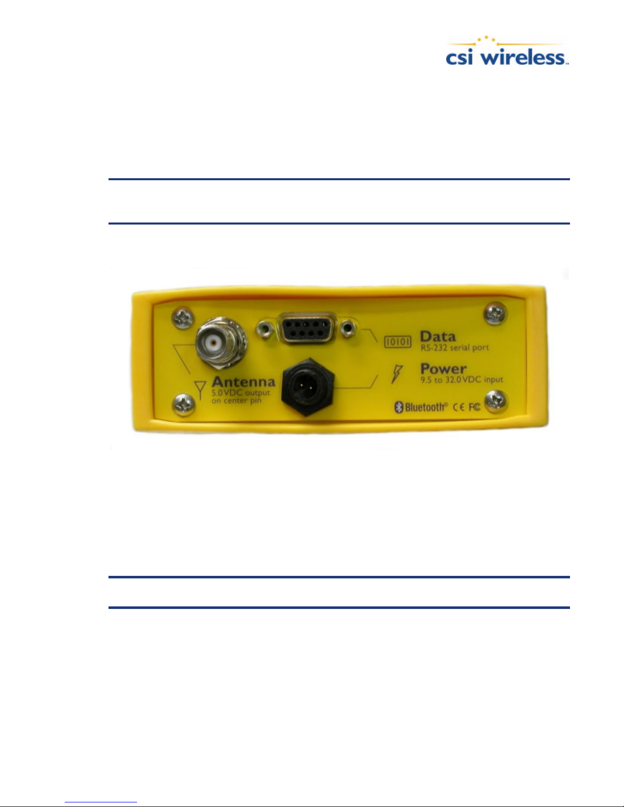
To communicate with the PowerMAX, you have two options, one DB9 socket connector is
available on the back panel, labeled ‘Data’, giving access to the RS-232 serial port of the PowerMAX.
The other option is Bluetooth communication (which is wireless) using a Bluetooth-enabled PDA
with a Bluetooth compatible software such as CSI’s PocketMAX. If you have a PDA or computer
that does not support Bluetooth natively, you often can supplement your computing device with a
Bluetooth card or dongle.
Caution – By default, the PowerMAX receiver offers 5.3 VDC across its RF connector
to power an active GPS antenna’s low noise amplifier (LNA). Connection to a GPS
antenna that doesn’t support a 5 VDC input could damage the antenna.
The following figure shows the various connections required for the PowerMAX.
Figure 1-1 Cable Interface
1.4 Configuring the PowerMAX
The PowerMAX has two primary communication ports referred to as Serial and Bluetooth. The
Serial and Bluetooth ports are fully independent and you may configure each port to have different
messages output at different rates. The Serial port may be configured for external correction input
or output binary message information or even RTCM corrections from a SBAS demodulator.
Note – The serial port is available via the single DB9 female connector located on the
rear panel labeled “Data”. The pin-out for this connector is provided in Table 1-5.
1.5 NMEA 0183 Message Interface
The PowerMAX uses a NMEA 0183 interface for interfacing, which allows you to easily make
configuration changes by sending text-type commands to the receiver.
Where appropriate, relevant commands for making the configuration changes are discussed in the
following chapters. The Programming Manual, however is devoted to describing the NMEA
interface in detail. You can download the Programming Manual from the CSI Wireless website.
PowerMAX User Manual 2
Page 16

1.6 Binary Message Interface
In addition to the NMEA interface, the PowerMAX also supports a selection of binary messages.
There is a wider array of information available through the binary messages, plus binary messages
are inherently more efficient with data. If your application has a requirement for raw measurement
data, for instance, this information is available only in a binary format. Consult the Programming
Manual for more information on Binary messages.
1.7 PocketMAX
PocketMAX is a free utility that CSI Wireless has developed to assist you with controlling and
monitoring your PowerMA X receiver. It requires a device that runs a Windows PocketPC 2000,
2002, or 2003 operating system. The PocketMAX Manual provides detailed information on how to
interact through both serial and bluetooth communications between your PowerMAX receiver and
your PDA based PocketMAX utility. This program allows you to graphically monitor the status and
function of the PowerMAX, in addition to providing an interface for its control. The PocketMAX
Manual is available for download from the CSI Wireless website.
We recommend that you gain your initial experience with the PowerMAX using this utility and then,
if you wish, migrate your work to a dumb terminal.
1.8 Default Parameters
Although presented in the following chapters, this section provides tables that detail the default
parameters of the PowerMAX as delivered.
Table 1-1 Default Applications
Application
WAAS (SBAS) – Default
e-Dif (if available)
Table 1-2 Default Port Settings
Port Baud Rate Data Bits Parity Stop Bit Interface Level
Serial,
Bluetooth
Table 1-3 Default GPS NMEA Message Output
9600 8 None 1 RS-232C
Port GPS NMEA Messages Update Rate
PowerMAX User Manual 3
Serial GGA, GSV, VTG, ZDA 1 Hz
Bluetooth GGA, GSV, VTG, ZDA 1 Hz
Page 17

Table 1-4 Default Parameters
Max DGPS Age Elevation Mask
1800 seconds
5°
1.9 Pin-Outs
The following tables detail the pin-out of the serial port of the PowerMAX.
Table 1-5 Serial Port Pin-out, RS-232C Interface Level
Pin Signal Description
2 TXD – serial NMEA 0183, binary, and RTCM output
3 RXD – serial NMEA 0183, binary, and RTCM input
5 Sig. Ground Signal return
6 Power Ground Power Ground (optional)
8 Power Power Input - 9.5 to 32 VDC (optional)
PowerMAX User Manual 4
Page 18

2. Introduction
This chapter provides a brief introduction to the PowerMAX and some of its high-level features.
The remaining chapters provide more detailed information on the workings of the product.
As mentioned in the previous chapter, if you are new to GPS and SBAS, we recommend that you
consult Appendix C for further information on these services and technology.
When powered for the first time, the PowerMAX will perform a ‘cold start’, which involves
acquiring the available GPS satellites in view and the SBAS differential service.
If SBAS is not available in your area, you may use either beacon or an external source of RTCM SC104 differential corrections. If you choose to use an external source of correction data, you will
need to ens ure that the external source supports an eight data bit, no parity, and one stop bit
configuration (8-N-1) and a baud rate between 4800 and 38400 baud.
This chapter describes the various modes of operation and features of your PowerMAX receiver.
2.1 GPS
The following sections describe the general operation of the PowerMAX GPS module.
2.1.1 Satellite Tracking
The PowerMAX automatically searches for GPS satellites, acquires the signal, and manages the
associated navigation information required for positioning and tracking. This is a hands -free mode of
operation. Satellite acquisition quality is described as a signal to noise ratio (SNR). A higher SNR is
indicative of better quality signal reception.
Note – The GPS engine is always operating, regardless of the DGPS mode of operation.
2.1.2 Positioning Accuracy
The PowerMAX is a sub -meter (horizontally), 95% accurate product under ideal conditions
(minimum error). When characterizing receiver performance, CSI Wireless gathers a 24 -hour data
set of positions in order to log the diurnal environmental effects and also to log 2 full GPS
constellation changes. Data sets shorter than 24 hours tend to provide more optimistic results.
Keeping in mind that this horizontal performance specification is a real world but ideal scenario test,
obstruction of satellites, multipath signals from reflective objects, and operating with poor
corrections will detract from the receiver’s ability to provide accurate, reliable positions.
Differential performance can also be compromised if the PowerMAX is used in a region without
sufficient ionospheric map coverage. If external corrections are used, the baseline separation
between the remote and base station antennas can affect performance.
Since the PowerMAX will be used in the real world, blockage of the line of sight to SBAS satellites is
often inevitable. In this case, beacon may be used instead. Our COAST technology provides solace
from obstruction of SBAS or beacon services for up to 30 to 40 minutes, depending on the amount
of tolerable performance drift. Section 2.5 discusses COAST technology in further detail.
PowerMAX User Manual 5
Page 19

The estimated positioning precision is accessible through the use of our PocketMAX utility
discussed in the PocketMAX Manual and NMEA 0183 command responses as described in Chapter
6 (The GST NMEA data message). As the receiver is not able to determine accuracy with respect
to a known location in real time (this is traditionally performed in post -mission analysis), the
precision numbers are relative in nature and are approximates.
2.1.3 Update Rates
The update rate of each NMEA and binary message of the PowerMAX can be set independently
with a maximum that is dependant upon the message type. Some messages have a 1 Hz maximum,
for example, while others are 5 Hz.
Higher update rates are valuable for applications where higher speeds are present (such as aviation)
or more frequent updates are required for manual navigational tasks, such as Agricultural Guidance.
2.2 SBAS
The following sections describe the general operation and performance monitoring of the SBAS
demodulator within the PowerMAX receiver.
2.2.1 Automatic Tracking
The SBAS demodulator featured within the PowerMAX will automatically scan and track the SBAS
satellite signals. This automatic tracking allows the user to focus on other aspects of their
application rather than ensuring the receiver is tracking SBAS correctly.
The SBAS demodulator features two-channel tracking that provides an enha nced ability to maintain
acquisition on a SBAS satellite in regions where more than one satellite is in view. This redundant
tracking approach will result in more consistent acquisition of a signal when in an area where signal
blockage of either satellite is possible.
2.2.2 SBAS Performance
The performance of the SBAS receiver is described in terms of a differential LED. SBAS requires a
line of sight to the SBAS satellites in order to acquire the signa l.
The BER number indicates the number of unsuccessfully decoded symbols in a moving window of
2048 symbols. Due to the use of forward error correction algorithms, one symbol is composed of
two bits. The BER value for both SBAS receiver channels is available in the RD1 NMEA data
message described in detail in the Programming Manual.
A lower BER indicates that data is being successfully decoded with fewer errors, providing more
consistent throughput. The bit error rate has a default, no -lock value of 500 or more. As the
receiver begins to successfully acquire the signal, it will result in a lower bit error rate. For best
operation, this value should be less than 150 and ideally less than 20.
Space-Based Augmentation Systems broadcast an ionospheric map on a periodic basis that may take
up to 5 minutes to receive upon startup. The PowerMAX uses the GPS broadcast ionospheric
model until it has downloaded the SBAS map, which can result in lower pe rformance as compared
to when the map has been downloaded. This will be the case for any GPS product supporting SBAS
services.
PowerMAX User Manual 6
Page 20

Caution – When the map has been downloaded, you may observe a position jump due
to the potential difference between the GPS ion ospheric model and the ionospheric
SBAS map. To minimize the impact of this issue on your use of the PowerMAX, you
may wish to wait up to five minutes before using the PowerMAX or issue the
$JQUERY,GUIDE<CR><LF> message to ‘ask’ the PowerMAX if it feels performance
will be sufficient for operation.
2.3 Radiobeacon DGPS
Many Marine authorities, such as Coast Guards, have installed networks of radiobeacons that
broadcast DGPS corrections to users of this system. With the increasing utility of these networks
for terrestrial applications, there is an increasing trend towards densification of these networks
inland.
2.4 Beacon Operation
The following sections describe the general operation and performance monitoring of the beacon
engine within the PowerMAX.
2.4.1 Tune Modes
The PowerMAX may be operated in either Automatic or Manual Beacon tune modes. In Automatic
Beacon Search (ABS) mode, the receiver will identify and tune to the station providing the strongest
DGPS signal. In Manual Tune mode, you specify the frequency to which the receiver will tune, or
select the desired beacon by name from the built-in global listing.
2.4.1.1 Automatic Beacon Search (ABS) Mode
When operating using the internal beacon sensor as the source of DGPS correction information,
the PowerMAX operates in Automatic Beacon Search (ABS) mode by default, selecting and tuning
to the most appropriate beacon without operator intervention. The PowerMAX’s internal beacon
receiver uses its two independent beacon cha nnels to identify and lock to DGPS beacons without
interrupting the continuous flow of RTCM data to the GPS receiver.
ABS mode is ideal for navigation applications over considerable areas, eliminating the need for
operator intervention when transitioning from one beacon coverage zone to another.
2.4.1.2 ABS Global Beacon Search
When powered for the first time in ABS mode, the PowerMAX initiates a Global Search, examining
each available DGPS beacon frequency, and recording Signal Strength (SS) measurements in units of
dBµV/m to the Global Search Table. The receiver uses these measured values to compute an
average SS, and noise floor, to sort the frequencies in descending order of SS. The beacon
receiver’s two channels cooperatively examine the frequencies with the highest SS measurements,
above the computed noise floor, to determine the station providing the strongest RTCM signal.
The receiver’s primary channel locks to the first identified DGPS broadcast, while the second
channel continues searching in the background for superior beacon signals. If no signal is available,
the PowerMAX will initiate a fresh Global Search, continuing this cycle until it finds a valid station.
PowerMAX User Manual 7
Page 21

2.4.1.3 ABS Backgrou nd Beacon Search
During the Background Search, the second beacon channel examines all frequencies at both 100
and 200 bps MSK bit rates to identify beacons possessing superior signal quality. If a DGPS
broadcast is identified that exhibits a 2 dB greater signal strength than that of the primary station,
the receiver will automatically switch to this beacon. No loss of lock occurs on the primary station
during the background scan.
The PowerMAX stores the current primary beacon in memory so that it is available upon
subsequent power-up.
2.4.1.4 Manual Tracking
In Manual tune mode, you may select a specific frequency and bit rate for the receiver to tune, or
specify the frequency only, allowing the PowerMAX to identify the correct MSK bit rate on its own.
This mode of operation is most useful when working in an area where you know the frequency
though not necessarily the MSK bit rate of the closest beacon.
2.4.2 Receiver Performance
The Signal to Noise Ratio (SNR) best describes the internal SBX-3B beacon receiver performance.
The SNR, me asured in dB, is the height of the signal above the noise floor. The higher the SNR, the
more successfully the beacon receiver is demodulating the signal.
Table 2-1 describes the beacon receiver quality of reception with respect to the SNR reading.
Table 2-1 Beacon Receiver Performance – SNR Reading
SNR Reception Description Approximate Data Throughput
>25 Excellent 100% data throughput
20 to 25 Very Good 100% data throughput
15 to 20 Good Good data throughput up to 100%
10 to 15 Stable Moderate to good data throughput
7 to 10 Intermittent Low data throughput
<7 No Lock No data throughput
2.5 COAST™ Technology
The PowerMAX receiver incorporates the CSI Wireless COASTTM technology that allows it to
operate with old correction data for up to 30 to 40 minutes or more without significant accuracy
degradation. The feature’s performance is attributed to sophisticated algorithms that are able to
anticipate how errors change during a period of correction loss.
Traditional receiver technology would experience an increasing degradation with increasing age of
corrections, resulting in less than adequate performance over a shorter period of time. COAST
technology provides more consistent positioning during periods when signal loss occurs, thus
bridging the gap to when the signal is reacquired. This means that the PowerMAX is more tolerant
than competing products to loss of SBAS, beacon or externally input RTCM SC -104 corrections.
PowerMAX User Manual 8
Page 22
2.6 Post Processing
The PowerMAX receiver is able to output raw measurement data for post processing applications.
The raw measurement and ephemeris data are contained in the Bin 95 and 96 messages
documented in the Programming Manua l. Both messages must be logged in a binary file.
We make a DOS-based RINEX translator available; however, RINEX has no facility to store station
information. Please contact CSI Wireless Inc. if you wish to use this utility.
2.7 Evaluating PowerMAX Performance
As mentioned earlier, CSI Wireless evaluates performance of the PowerMAX receiver with the
objective of determining best-case performance in a real-world environment. Our static testing has
shown that the PowerMAX achieves a performance better than one meter 95% of the time.
The qualifier of 95% is a statistical probability. Often you may see manufacturers using a probability
of ‘rms’ or standard deviation. Performance measures with these probabilities are not directly
comparable to a 95% measure since they are a lower probability (less than 70% probability). This
means that less often, a product would position within a radius of the prescribed amount.
The following table summarizes the common horizontal statistical probabilities.
Table 2-2 Horizontal Accuracy Probability Statistics
Accuracy Measure Probability (%)
Rms (root mean square) 63 to 68
CEP (circular error probability) 50
2drms (twice the distance root mean square) 95 to 98
R95 (95% radius) 95
It is possible to convert from one statistic to another using the following table. Using the value
where the ‘From’ row meets the ‘To’ column, multiply the accuracy by this conversion value.
Table 2-3 Horizontal Accuracy Statistic Conversions
To
CEP rms R95 2drms
CEP 1 1.2 2.1 2.4
rms 0.83 1 1.7 2.0
R95 0.48 0.59 1 1.2
From
2drms 0.42 0.5 0.83 1
For example, if Product A after test results in an accuracy of 90 cm 95% (R95) and you want to
compare this to Product B that has a sub-meter horizontal rms specification, select the value from
where the ‘R95’ row and the ‘rms’ column intersect (to convert to rms).
PowerMAX User Manual 9
Page 23

You will see tha t this conversion value is 0.59. Multiply the 90 cm accuracy by this conversion
factor and the result will be 53 cm rms. If you now compare this to Product B’s specification of submeter rms, you can see the first Product A would offer better performance .
To properly evaluate one receiver against another statically, they should be using identical
correction input (from an external source) and also share the same antenna using a power splitter
(equipped with appropriate DC-blocking of the receivers and a bias-T to externally power the
antenna). With this type of setup, the errors in the system are identical with the exception of
receiver noise.
Although this is a comparison of the GPS performance quality of a receiver, it excludes other
performance merits of a GPS engine. The dynamic ability of a receiver should be compared in a
similar way with the test subjects sharing the same antenna. Unless a receiver is moving, its
software filters are not stressed in a similar manner to the final product application. When testing
dynamically, a much more accurate reference would need to be used, such as an RTK system so that
a ‘truth’ position per epoch is available.
Further, there are other performance merits of a GPS engine, such as its ability to maintain a lock
on GPS and SBAS satellites. In this case, the same GPS antenna should be shared between the
receiver test subjects. For the sake of comparing the tracking availability of one receiver to another,
no accurate ‘truth’ system is required, unless performance testing is also to be analyzed. Again, an
RTK system would be required; however, it’s questionable how its performance will fair with
environments where there are numerous obstructions, such as foliage. Other methods of providing
a truth reference may need to be provided through observation times on surveyed monuments or
traversing well-known routes.
If you require assistance in developing a test setup or procedure for evaluating the PowerMAX,
please contact CSI Wireless.
PowerMAX User Manual 10
Page 24
3. Features
This chapter describes the main features of the PowerMAX system. The PowerMAX system is
composed primarily of the following parts:
• A PowerMAX receiver
• An MGL-3 antenna
• Associated cables
This chapter provides details on the fundamental operating modes of the PowerMAX receiver and
its associated default parameters.
3.1 System Parts List
The following list of standard equipment is included with the PowerMAX system:
• One PowerMax Receiver (P/N 803-0030-01A)
• One MGL-3 Antenna (P/N 804 -3003-05A)
• One Magnetic Mount (P/N 725-0007-014)
• One 3 Meter Power Cable (P/N 054-0009-000)
• One 3 Meter Data Cable (P/N 050-0011-022)
• One 5 Meter Antenna Cable (P/N 052-0005-000)
• One Manual CD (P/N 132-0127-000) containing the PowerMAX Reference Manual
3.2 Cable Interface
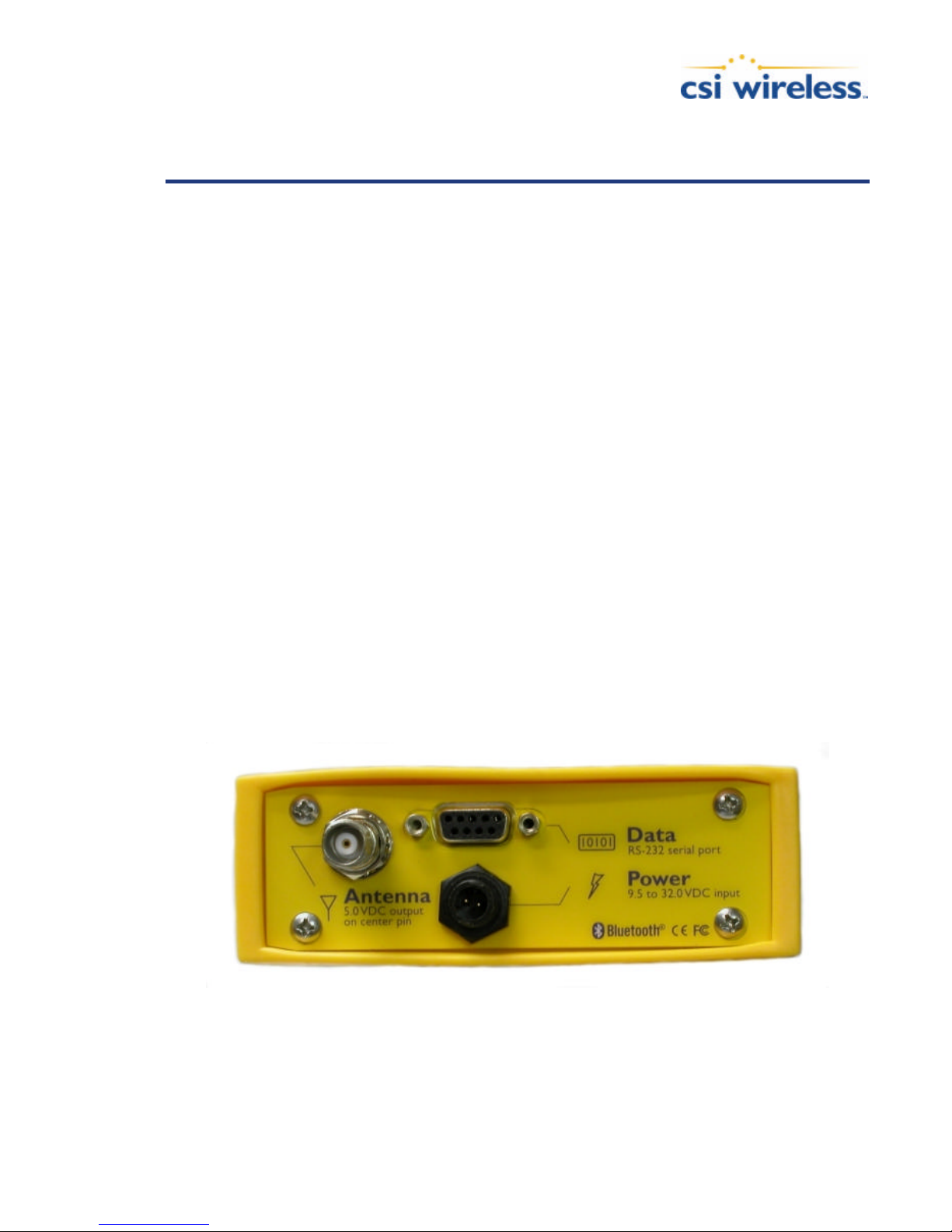
The PowerMAX receiver requires power and antenna cable interfaces. The data cable is optional if
you intend to use the wireless bluetooth interface. The following figure shows the various
connections located on the rear panel of the PowerMAX enclosure.
Figure 3-1 Cable Interface
3.2.1 Routing and Securing the Cable
When choosing a route for PowerMAX cables.
PowerMAX User Manual 11
Page 25

• Avoid running cables in areas of excessive heat
• Keep antenna cables away from corrosive chemicals
• Do not run the extension cable through door or window jams
• Keep the cable away from rotating machinery
• Do not bend excessively or crimp the extension cable
• Be careful not to apply tension to the cable
• Remove unwanted slack from the cable at the opposite end to the antenna
• Secure the cable route using plastic tie wraps
Warning – Improperly installed cables near machinery can be dangerous
3.3 Environmental Requirements
The equipment supplied with the PowerMAX system has specific environmental limits that you
should ensure are met when storing and using the system.
The PowerMAX receiver is designed to be stored between -40°C and +85°C. The operating
temperature range is -30°C and +70°C. The PowerMAX is specified to operate with humidity up to
95% non-condensing.
The antennas are designed to operate in an outdoor environment with 100% relative humidity,
condensing.
3.4 Power Requirements
The PowerMAX is powered via a power cable that interfaces to the enclosure’s ‘Power’ connector.
This system accepts an input voltage between 9.5 and 32 VDC. There is a second option for
powering the PowerMAX. It is possible to power it through the serial port (labeled Data) instead of
through the power connector. The PowerMAX is specially set up to receive power on pin 8 and
power ground on pin 6. Refer to Table 3-2 for the serial port pin out. For best performance, the
supplied power should be continuous and clean. The following table details the power specifications
of the PowerMAX.
Table 3-1 Power Requirements
Input Voltage Input Current Input Power
9.5 to 32 VDC < 250 mA @ 12 VDC (no antenna) < 3 W Nominal (no antenna)
3.5 Antenna Placement
The GPS antenna included should be mounted pursuant to the following requirements:
• The PowerMAX receiver computes a position based upon measurements from each satellite to the
location of the GPS antenna’s phase center. Mount the GPS antenna in the location for which you
desire a position. When choosing a location to mount the antenna, please ensure that there is an
unobstructed hemisphere of sky available to the GPS antenna. This will ensure that GPS and SBAS
satellites are not masked by obstructions, potentially reducing system performance.
PowerMAX User Manual 12
Page 26

• It is important to locate any transmitting antennas away from the GPS antenna by several feet or more.
This will help to ensu re that tracking performance of the PowerMAX is not compromised, giving you
the best performance possible.
• Make sure that there is sufficient length of the antenna extension cable available in order to be able to
connect it to the PowerMAX enclosure.
Do not locate the antenna where environmental conditions exceed those specified in Section 3.3.
3.6 Powering the PowerMAX Receiver
There are two different ways of powering the PowerMAX receiver, so, the first step is to terminate
the power leads of the power cabl e or pins 6 and 8 of the serial cable. There are a variety of power
connectors and terminals on the market from which to choose, depending on your specific
requirements. We suggest that a weather-tight connection and connector be used if the connection
will be located outside or if it will be part of a portable system.
Caution – Do not apply a voltage higher than 32 VDC as this will damage the receiver
and void the warranty
To turn on the PowerMAX receiver:
• Connect the red wire of the cable’s power input (or pin 8 on the serial cable) to DC positive (+).
• Connect the black wire of the cable’s power input (of pin 6 on the serial cable) to DC negative (-).
The PowerMAX features reverse polarity protection to prevent damage if the power leads are
accidentally reversed.
A 1.0 A fast-blow fuse, situated in-line of the power input of the extension cable and protects the
PowerMAX receiver from power surges. The fuse container should remain accessible after
installation.
The PowerMAX will start when an acceptable voltage is applied to the power leads of the extension
cable. Be careful not to provide a voltage higher than the input range as this could damage the
system.
Caution – Do not operate the PowerMAX receiver with the fuse bypassed. Such a
modification will void the product warranty.
3.7 Serial Port Interface
There is one serial port on the PowerMAX and it is compatible with the RS-232C interface level to
communicate with external data loggers, navigation systems, PC computers, PDAs and other
devices. This serial port is accessible via the rear panel of the PowerMAX enclosure and has a
‘Data’ label. You can interface most devices to the PowerMAX directly with a serial cable,
accommodating any gender changes necessary, or with the addition of a null modem as necessary.
The serial port should be used for firmware updates. The following table provides the pin
assignments for the serial port.
PowerMAX User Manual 13
Page 27
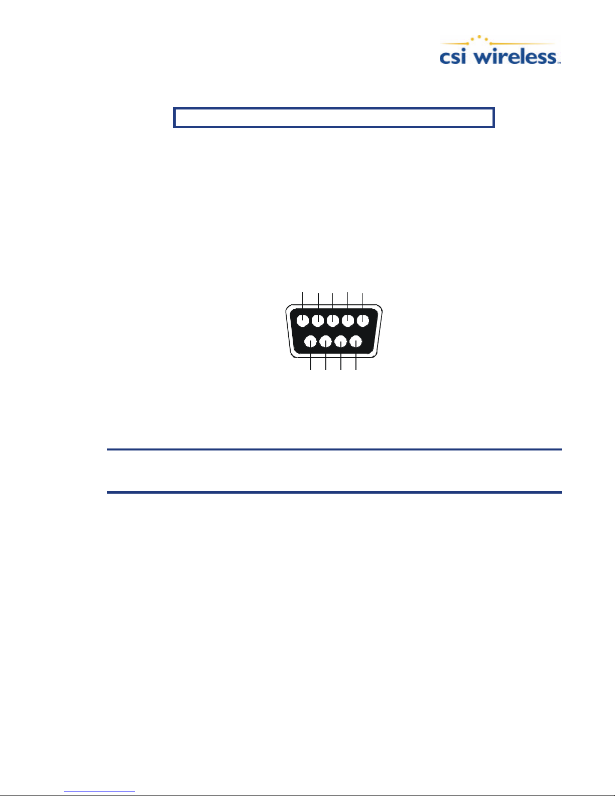
Table 3-2 Serial Port Pin-out, RS-232C Interface Level
123
4
67958
Pin Signal Description
2 TXD NMEA 0183, binary, and RTCM output for the MAIN port
3 RXD NMEA 0183, binary, and RTCM input for the MAIN port
5 Sig. Ground Signal return
6 Power Ground Power Ground (optional)
8 Power Power Input ( 9.5 to 32 VDC ) (optional)
Figure 3-2 displays the numbering scheme for extension cable’s DB9 socket connectors (female).
The associated numbering for the plug connector (male) is a mirror reflection of scheme showed in
this figure.
Figure 3-2 DB9 Socket Numbering
Refer to Appendix B for further interfacing information.
Note - For successful communications, the baud rate of the PowerMAX serial ports
must be set to match that of the devices to which they are connected. The
Programming Manual describes the baud rate change command.
3.8 Bluetooth Interface
Bluetooth is a wireless communication technology that enables seamless data connections between
a wide range of devices through short -range digital two-way radio. In the case of the PowerMAX, it
is equipped with Bluetooth technology and requires another Bluetooth device with which to
communicate (a Bluetooth-capable PDA, for example). The Bluetooth wireless module inside the
PowerMAX is a power class 1 device supporting version 1.1 of the Bluetooth standard, and has
been certified.
The bluetooth port should not be used for firmware updates; it is recommended you use the serial
port for any software updates.
PowerMAX User Manual 14
Page 28
3.9 Factory Default Parameters
The following table shows the application (firmware) present within the PowerMAX engine.
Table 3-3 Firmware Applications
Application
WAAS (SBAS) - Default
BEACON
The following table outlines the default communication parameters of the PowerMAX receiver.
Table 3-4 Default Port Settings
Port Baud Rate Data Bits Parity Stop Bit Interface Level
Serial and
Bluetooth
9600 8 None 1 RS-232C
Table 3-5 Default GPS NMEA Message Output
Port GPS NMEA Messages Update Rate
Serial GGA, GSV, VTG, ZDA 1 Hz
Bluetooth GGA, GSV, VTG, ZDA 1 Hz
Table 3-6 Default Parameters
Max DGPS Age Elevation Mask
1800 seconds
5°
Note - Any changes you make to the PowerMAX configuration need to be saved with
the $JSAVE NMEA command in order to be present for a subsequent power-cycle.
3.10 LED Indicators
The PowerMAX features diagnostic LEDs that provide a quick indication of the receiver’s status.
These LEDs are visible on the front panel display.
The five diagnostic LEDs visible on the front panel display of the PowerMAX provide the following
information:
PowerMAX User Manual 15
Page 29

Table 3-7 LED Indicator Definitions
LED Color Function
PWR Red Power indicator – when the PowerMAX is powered, this LED will illuminate
GPS Yellow GPS lock indicator – this LED will blink a few times on startup. Once the PowerMAX achieves a solid GPS lock,
DIFF Yellow Differential lock indicator – this indicator will illuminate continuously when the PowerMAX has achieved a solid
DGPS Green DGPS position indicator – this LED will illuminate when the receiver has achieved a differential position and the
Blue Bluetooth indicator – this LED will illuminate when there is a bluetooth connection between the PowerMAX and
Once power is applied to the PowerMAX, the power LED will illuminate solidly and the GPS LED
will blink a few times, followed by a lamp test. Once the GPS lock LED has finished blinking a few
times, you will see the GPS lock, Differential lock, and the DGPS position LEDs illuminate in
sequence a few times and then go out.
this LED will remain illuminated. If this LED continues to blink, it could be an indication of a receiver hardware
failure.
SBAS or beacon lock with better than a 150 bit error rate (BER) or when it is successfully receiving externally
input RTCM corrections. If the SBAS BER is higher than 15 0 but the receiver is still locked, this LED will blink,
showing that lock is marginal.
psuedorange residuals are below that set with the $JLIMIT command. The default value is a psuedorange residual
of better than 10.0 meters. If the residual value is worse than the current threshold, the green DGPS LED will
blink indicating that differential mode has been attained but that the residual has not yet met the threshold.
a Bluetooth compatible device and off when there is no bluetooth connection.
When the PowerMAX acquires a GPS lock, the yellow GPS lock LED will illuminate solidly.
Similarly, the differential LED will illuminate when the SBAS demodulator or beacon module has
acquired lock, or externally input corrections are being successfully received. The green DGPS
position LED will illuminate when the receiver has acquired a GPS lock, differential lock, and has
applied corrections within the position solution. The above table provides more detail on LED
status.
The following image displays the front panel layout of the PowerMAX receiver, including the
location and labeling of each LED. For more information on LED operation and troubleshooting,
refer to Chapter 8.
Figure 3-3 PowerMAX Front Panel
PowerMAX User Manual 16
Page 30

4. Operation Basics
This chapter introduces the general operational features of the PowerMAX system, operating
modes, and receiver default operating parameters.
4.1 Powering PowerMAX
As described in Chapter 2, Introduction, the PowerMAX is powered by connecting the red and
black power leads or pins 6 and 8 to a 9.5 to 32 VDC power source and ground. Once both leads
are connected, the PowerMAX will be immediately powered.
With the application of power, the PowerMAX system will proceed through an internal start-up
sequence, however it will be ready to communicate immediately.
When installed such that the antenna has an unobstructed view of the sky, the PowerMAX will
provide a position quickly, within approximately 60 seconds. SBAS lock requires approximately 30
seconds to acquire. Beacon lock requires approximately 60 seconds to acquire.
Note - It can take up to 5 minutes for a full ionospheric map to be received from SBAS.
Optimum accuracy will be obtained once the PowerMAX is processing corrected
positions using complete ionospheric information.
4.2 Communicating with PowerMAX
The PowerMAX features two serial ports that may be configured independently from each other
(Ports Serial and Bluetooth). The ports may be confi gured for any mixture of NMEA 0183, binary,
and RTCM SC-104 data. The usual data output is limited to NMEA data messages since these are
industry standard.
Note - If you require different data types to be output from the PowerMAX
simultaneously (such as NMEA and binary or NMEA and RTCM), ensure that the
software used for logging and processing of the data has been designed to correctly
parse the different data types from the single stream of data. Alternatively, you may
also use the two ports (serial an d Bluetooth) to separate the different data types and at
different output rates.
4.2.1 NMEA 0183 Interface
NMEA 0183 is a communications standard established by the National Marine Electronics
Association (NMEA) and provides data definitions fo r a variety of navigation and related equipment.
Such instruments supported include gyrocompasses, Loran receivers, echo sounders, GPS receivers,
and more. NMEA functionality is virtually standard on all GPS equipment available. NMEA has an
ASCII character format that allows you to read the data via terminal software on the receiving
device (if possible). One second of example NMEA data from the PowerMAX follows:
$GPGGA,144049.0,5100.1325,N,11402.2729,W,1,07,1.0,1027.4,M,0,M,,0100*61
$GPVTG,308.88,T,308.88,M,0.04,N,0.08,K*42
$GPGSV,3,1,10,02,73,087,54,04,00,172,39,07,66,202,54,08,23,147,48*79
$GPGSV,3,2,10,09,23,308,54,11,26,055,54,15,00,017,45,21,02,353,45*78
$GPGSV,3,3,10,26,29,257,51,27,10,147,45,,,,,,,,*74
PowerMAX User Manual 17
Page 31

The PowerMAX supports a variety of standard and proprietary NMEA messages. These messages
are used to configure the PowerMAX and also contain the required information from the
PowerMAX. You may configure a selection of NMEA 0183 data messages on one port at various
update rates (each message has a maximum update rate) and a different selection of NMEA 0183
messages with different rates on the other port.
Chapter 6 presents information relating to the NMEA interface of the PowerMAX. Appendix D Resources provides contact information should you wish to purchase a copy of the NMEA 0183
standard.
4.2.2 Binary Interface
Binary messages may be output from the PowerMAX simultaneously as NMEA 0183 data. Binary
messages have a proprietary definition and would likely require custom software support if you wi sh
to use them. Binary messages are inherently more efficient than NMEA 0183 and would be used
when you require maximum communication efficiency. Use of binary messages for most users is not
recommended - the NMEA interface allows you to control the operation of the PowerMAX and
also receive most types of information regarding status and positioning information.
Note – If you wish to log binary data, please ensure that your logging software has
opened the file as a binary file, otherwise you may lose data.
4.2.3 RTCM SC-104 Protocol
RTCM SC-104 is a standard that defines the data structure for differential correction information
for a variety of differential correction applications. It has been developed by the Radio Technical
Commission for Maritime services (RTCM) and has become an industry standard for communication
of correction information. RTCM is a binary data protocol and is not readable via a terminal
program. It appears as ‘garbage’ data on-screen since it is a binary format and not ASCII text. The
following is an example of how the RTCM data appears on-screen:
mRMP@PJfeUtNsmMFM{nVtIOTDbA^xGh~kDH`_FdW_yqLRryrDuhcB\@}N`ozbSD@O^}nr
GqkeTlpLLrYpDqAsrLRrQN{zW|uW@H`z]~aGxWYt@I`_FxW_qqLRryrDCikA\@Cj]DE]|
E@w_mlroMNjkKOsmMFM{PWDwW@HVEbA^xGhLJQH`_F`W_aNsmMFM[WVLA\@S}amz@ilIu
Pqx~_IZhTCpLLrYpdP@kOsmMFM[kVDHwVGbA^P{WWuNt_SW_yMsmMnqdrhcC\@sE^ZfC@
}vJmNGAHJVhTCqLRryrdviStW@H_GbA^P{wxu[K
RTCM has various levels of detail; however the highest level is the message. RTCM defines
numerous messages that contain specifi c information. The PowerMAX receiver processes the C/A
code and does not support more advanced methods of differential positioning, such as real-time
kinematic (RTK) that uses different RTCM message types. Considering this fact, only certain RTCM
messages are important for use with the PowerMAX:
• Type 1 and Type 9 messages, both of which contain similar information. These two messages contain
pseudorange corrections and range rate corrections to each GPS satellite.
• The Type 2 message contains delta differential corrections that are used when the remote receiver is
using a different satellite navigation message than used by the base station.
• The Type 5 message contains GPS constellation health information used for improving tracking
performance of a GPS rec eiver
PowerMAX User Manual 18
Page 32

• The Type 6 message contains null information, and is broadcast so that a beacon receiver demodulating
the data from the broadcast does not lose lock when the beacon station has no new data to transmit.
Note - RTCM is a local area data standard. This means that when positioning with
external correction input to the PowerMAX from an external source or outputting
corrections from the PowerMAX to another GPS receiver, performance will degrade
as a function of distance from the base station. The additio nal degradation will depend
on the difference in observed orbit and ionospheric errors between the reference
station and the remote unit. A general rule of thumb would be an additional 1 m error
per 100 miles. This error is often seen as a bias in positioning, resulting in a position
offset. The scatter of the receiver is likely to remain close to constant.
The RTCM SC-104 data output by the PowerMAX is converted from the RTCA SC -159 data
broadcast by SBAS networks.
Appendix D - Resources contains the contact information should you wish to purchase a copy of
the RTCM SC-104 specification.
4.3 Configuring PowerMAX
All aspects of PowerMAX operation may be configured through the serial port with the use of
NMEA 0183 commands, or using the PocketMAX utility discussed in the PocketMAX manual.
These commands are described in the Programming Manual. The following items are userconfigurable:
• Selecting one of the three on -board applications (SBAS, Beacon or e-Dif, if present)
• Setting the baud rate of both communication ports
• Choosing which NMEA data messages to output on the dual serial ports and the update rate of each
message
• Setting the maximum differential age cut-off
• Setting the satellite elevation angle cut-off mask
4.4 Firmware
The software that runs the PowerMAX is often referred to as firmware since it operates at a low
level. There are two types of firmware within the PowerMAX for the on-board digital signal
processor (DSP) and the ARM processor. Each of these types of firmware may be upgraded in the
field through the main serial port as new revisions become available.
The ARM processor of the PowerMAX engine supports two simultaneous versions of firmware.
Only one of them is in operation at any given time. These two versions of firmware may have
different f unctionality, and are also referred to as applications.
The PowerMAX currently ships with a SBAS (WAAS) application and the e-Dif application. The
Programming Manual describes the $JAPP command used to change between the two PowerMAX
applications. Withi n the WAAS application, there are two differential modes, being WAAS and
beacon. The Programming Manual describes the $JDIFF command used to change between the two
differential modes.
PowerMAX User Manual 19
Page 33

4.5 Configuring Data Message Output
The PowerMAX features two primary bi -directional ports referred to as Serial and Bluetooth. GPS
data messages for both ports are easily configured by sending NMEA commands to the PowerMAX
through either of its communication ports (the output of the Serial Port can be configured through
Bluetooth, for instance and vice versa). The $JASC NMEA message discussed in detail in the
Programming Manual allows you to turn messages on and off as you require.
4.5.1 This Port and the Other Port
The NMEA interface for the Serial Port and the Bluetooth Port use ‘This’ and ‘Other’ terminology.
When interfacing to a port for the sake of turning data messages on or off, on that same port, the
port is referred to as ‘This’ port. If you wish to turn a data message on or off, on the opposite port
to which you are communicating, the opposite port is referred to as the ‘Other’ port.
For example, if you are communicating with the PowerMAX Serial Port, and wish to turn the
GPGGA message on at an update rate of 5 Hz on the Bluetooth Port, the following command would
be used.
$JASC,GPGGA,5,OTHER<CR><LF>
If you wish to turn the GPGGA message on at 5 Hz on the Serial Port, you would issue the
following command.
$JASC,GPGGA,5<CR><LF>
When turning a message on or off on ‘This’ port, you do not need to indicate ‘This’ at the end of
the message. Consult the Programming Manual for more information on NMEA messages.
4.6 Saving PowerMAX Configuration
Each time that you change the configuration of the PowerMAX, you may wish to save the new
configuration so the receiver does not have to be reconfigured again for the next power cycle.
The save the settings, issue the $JSAVE command and the receiver will record the current
configuration to non-volatile memory. The PowerMAX will let you know when the save process
has been completed which can take approximately five seconds.
4.7 Using the Serial Port for RTCM Input
The PowerMAX Serial port can be used to accommodate externally supplied corrections input
according to the RTCM SC -104 protocol.
To use the Serial port of the PowerMAX for correction input you must set the PowerMAX to
operate in other differential mode using the following command while connected to the Serial port:
Although the following RTCM SC-104 message types don’t all contain differential data, the
PowerMAX is compatible with them.
PowerMAX User Manual 20
$JDIFF,THIS<CR><LF>
Page 34

• Type 1
• Type 2
• Type 3
• Type 5
• Type 6
• Type 7
• Type 9
• Type 16
To return to using SBAS as the correction source, send the following command to the
PowerMAX:
$JDIFF,WAAS<CR><LF>
To return to using beacon as the correction source, send the following command to the
PowerMAX:
$JDIFF,BEACON<CR><LF>
You will find detailed information on NMEA messages supported by the PowerMAX in Chapter
6 NMEA 0183 Messages.
PowerMAX User Manual 21
Page 35

5. NMEA 0183 Messages
The PowerMAX GPS module supports a selection of NMEA 0183 and proprietary binary
messages. This chapter identifies the selection of standard and proprietary NMEA 0183
messages for the PowerMAX receiver.
5.1 NMEA Message Elements
NMEA 0183 messages have a common structure, consisting of a message header, data fields,
checksum, and carriage return/line feed message terminator. An example NMEA sentence
follows:
$XXYYY,zzz,zzz,zzz…*xx<CR><LF>
The components of this generic NMEA message example are displayed in Table 6-1.
Table 5-1 NMEA Message Elements
Element Description
$ Message header character
XX NMEA Talker field. GP indicates a GPS talker
YYY Type of GPS NMEA Message
zzz Variable Length Message Fields
*xx Checksum
<CR> Carriage Return
<LF> Line Feed
Null, or empty fields occur when no information is available for that field.
PowerMAX User Manual 22
Page 36

5.2 Data Messages
The following subsections describe the NMEA data messages listed in the Table below in detail.
Table 5-2 Data Messages
Message Max Rate Description
GPGGA 5 Hz Global Positioning System Fix Data
GPGLL 5 Hz Geographic Position – Latitude/Longitude
GPGSA 1 Hz GNSS (Global Navigation Satellite System) DOP and Active Satellites
GPGST 1 Hz GNSS Pseudorange Error Statistics
GPGSV 1 Hz GNSS Satellites in View
GPRMC 5 Hz Recommended Minimum Specific GNSS Data
GPRRE 1 Hz Range residual message
GPVTG 5Hz Course Over Ground and Ground Speed
GPZDA 5 Hz Time and Date
RD1 1 Hz SBAS diagnostic information (pro prietary NMEA message)
$PCSI,1 1 Hz This is a proprietary beacon status message
5.2.1 GGA Data Message
The GGA message contains detailed GPS position information, and is the most frequently used
NMEA data message. In the table below, the GGA data message is broken down into its
components. This message takes the following form:
$GPGGA,hhmmss.ss,ddmm.mmmm,s,dddmm.mmmm,s,n,qq,pp.p,saaaaa.aa,M, ±xxxx.xx,
M,sss,aaaa*cc<CR><LF>
Table 5-3 GGA Data Messa ge Defined
Field Description
hhmmss.ss UTC time in hours, minutes, seconds of the GPS position
ddmm.mmmmm Latitude in degrees, minutes, and decimal minutes
s s = N or s = S, for North or South latitude
dddmm.mmmmm Longitude in degrees, minutes, and decimal minutes
s s =E or s = W, for East or West longitude
n
qq Number of satellites used in position computation
pp.p HDOP =0.0 to 9.9
saaaa.aa Antenna altitude
M Altitude units, M = meters
±xxxx.xx
M Geoidal separation units, M = meters
sss Age of differential corrections in seconds
aaa Reference station identification
*cc Checksum
<CR><LF> Carriage return and line feed
Quality indicator, 0 = no position, 1 = undifferentially corrected position, 2 =
differentially corrected position, 9= position computed using almanac
Geoidal separation (needs geoidal height option)
PowerMAX User Manual 23
Page 37

5.2.2 GLL Data Message
The GLL message contains Latitude and Longitude. In the table below, the GLL data message is
broken down into its components. This message has the following format:
$GPGLL,ddmm.mmmm,s,dddmm.mmmm,s,hhmmss.ss,s*cc<CR><LF>
Table 5-4 GLL Data Message Defined
Field Description
ddmm.mmmmm Latitude in degrees, minutes, and decimal minutes
s s = N or s = S, for North or South latitude
dddmm.mmmmm Longitude in degrees, minutes, and decimal minutes
s s = E or s = W, for East or West longitude
hhmmss.ss UTC time in hours, minutes, and seconds of GPS position
s Status, s = A = valid, s = V = invalid
*cc Checksum
<CR><LF> Carriage return and line feed
5.2.3 GSA Data Message
The GSA message contains GPS DOP and active satellite information. Only satellites used in
the position computation are present in this message. Null fields are present when data is
unavailable due to the number of satellites tracked. The table below breaks down the GSA
message into its components. This message has the following format:
$GPGSA,a,b,cc,dd,ee,ff,gg,hh,ii,jj,kk,mm,nn,oo,p.p,q.q,r.r *cc<CR><LF>
Table 5-5 GSA Data Message Defined
Field Description
a
b Position mode, 1 = fix not available, 2 = 2D fix, 3 = 3D fix
cc to oo Satellites used in the position solution, a null field occurs if a channel is unused
p.p Position Dilution of Precision (PDOP) = 1.0 to 9.9
q.q Horizontal Dilution of Precision (HDOP) = 1.0 to 9.9
r.r Vertical Dilution of Precision (VDOP) = 1.0 to 9.9
*cc Checksum
<CR><LF> Carriage return and line feed
Satellite acquisition mode M = manually forced to 2D or 3D, A = automatic swap
between 2D and 3D
PowerMAX User Manual 24
Page 38

5.2.4 GST Data Message
The GST message contains Global Navigation Satellite System (GNSS) psuedorange error
statistics. The table below breaks down the GST message into its components. This message
has the following format:
$GPGST,hhmmss.ss,a.a,b.b,c.c,d.d,e.e,f.f,g.g *cc<CR><LF>
Table 5-6 GST Data Message Defined
Field Description
hhmmss.ss UTC time in hours, minutes, seconds of the GPS position
a.a
b.b Standard deviation of semi-major axis of error ellipse (meters)
c.c Standard deviation of semi-minor axis of error ellipse (meters)
d.d Orientation of semi-major axis of error ellipse (degrees)
e.e Standard deviation of latitude error (meters)
f.f Standard deviation of longitude error (meters)
g.g Standard deviation of altitude error (meters)
*cc Checksum
<CR><LF> Carriage return and line feed
Root mean square (rms) value of the standard deviation of the range inputs to the
navigation process. Range inputs include pseudoranges and differential GNSS (DGNSS)
corrections
5.2.5 GSV Data Message
The GSV message contains GPS satellite information. Null fields occur where data is not
available due to the number of satellites tracked. The Table below breaks down the GSV data
message into its components. This message has the following format:
$GPGSV,t,m,n,ii,ee,aaa,ss,…ii,ee,aaa,ss,*cc<CR><LF>
Table 5-7 GSV Data Message Defined
Field Description
t Total number of messages
m Message number, m = 1 to 3
n Total number of satellites in view
ii Satellite number
ee Elevation in degrees, ee = 0 to 90
aaa Azimuth (true) in degrees, aaa = 0 to 359
ss SNR (dB) + 30, ss = 0 to 99
*cc Checksum
<CR><LF> Carriage return and line feed
PowerMAX User Manual 25
Page 39

5.2.6 RMC Data Message
The RMC message contains recommended minimum specific GPS data. The table below breaks
down the RMC data message into its components. This message has the following format:
$GPRMC,hhmmss.ss,a,ddmm.mmm,n,dddmm.mmm,w,z.z,y.y,ddmmyy,d.d,v
*cc<CR><LF>
Table 5-8 RMC Data Message Defined
Field Description
hhmmss.ss UTC time in hours, minutes, seconds of the GPS position
a Status is valid if a = A, status is invalid if a = V
ddmm.mmmmm Latitude in degrees, minutes, and decimal minutes
n S = N or s = S, for North or South latitude
dddmm.mmmmm Longitude in degrees, minutes, and decimal minutes
w S = E or s = W, for East or West longitude
z.z Ground speed in knots
y.y Track made good, referenced to true north
ddmmyy UTC date of position fix in day, month, year
d.d Magnetic Variation in degrees
v Variation sense v = E = East, v = W = West
*cc Checksum
<CR><LF> Carriage return and line feed
5.2.7 RRE Data Message
The RRE message contains the satellite range residuals and estimated position error. The table
below breaks down the RRE data message into its components. This message has the following
format:
$GPRRE,n,ii,rr…ii,rr,hhh.h,vvv.v *cc<CR><LF>
Table 5-9 RRE Data Message Defined
Field Description
n Number of satellites used in position computation
ii Satellite number
rr Range residual in meters
hhh.h Horizontal position error estimate in meters
vvv.v Vertical position error estimate in meters
*cc Checksum
<CR><LF> Carriage return and line feed
PowerMAX User Manual 26
Page 40

5.2.8 VTG Data Message
The VTG message contains velocity and course information. The table below breaks down the
VTG data message into its components. This message has the following format:
$GPVTG,ttt,c,ttt,c,ggg.gg,u,ggg,gg,u*cc<CR><LF>
Table 5-10 VTG Data Message Defined
Field Description
ttt True course over ground, ttt = 000 to 359, in degrees
c True course over ground indicator, c = T always
ttt
c Magnetic course over ground Indicator, always c = M
ggg.gg Speed over ground, 000 to 999 knots
u Speed over ground units, u = N = Nautical mile/h
ggg.gg Speed over ground, 000 to 999 km/h
u Speed over ground units, u = K = kilometer/h
*cc Checksum
<CR><LF> Carriage return and line feed
Magnetic course over ground, ttt = 000 to 359, in degrees (output with magnetic model
option only)
5.2.9 ZDA Data Message
The ZDA message contains Universal Time information. The table below breaks down the
ZDA data message into its components. This message has the following format:
$GPZDA,hhmmss.ss,dd,mm,yyyy,xx,yy*cc<CR><LF>
Table 5-11 ZDA Data Message Defined
Field Description
hhmmss.ss UTC time in hours, minutes, seconds of the GPS position
dd Day, dd = 0 to 31
mm Month, mm = 1 to 12
yyyy Year
xx Local zone description in hours, xx = -13 to 13
yy Local zone description in minutes, yy = 0 to 59
*cc Checksum
<CR><LF> Carriage return and line feed
PowerMAX User Manual 27
Page 41

5.2.10 RD1 Data Message
The RD1 message contains diagnostic information for SBAS operation. The table below breaks
down the RD1 data message into its components. This message has the following format:
$RD1,SecOfWeek,WeekNum,FreqMHz,DSPLocked,BER -
BER2,AGC,DDS,Doppler,DSPStat,ARMStat,DiffStatus,NavCondition *cc<CR><LF>
Table 5-12 RD1 Data Messa ge Defined
Field Description
SecOfWeek The second of GPS week (may be a couple of seconds old)
WeekNum The GPS week number
FreqMHz The L-band frequency in MHz (1475.4200 is used for SBAS)
DSPLocked 1 if DSPStat = 1B or 1F
BER-BER2 Bit error rate – bit error rates are given for both SBAS satellites being tracked
AGC L-band Signal strength
DDS 0.0 for SBAS
Doppler 0 for SBAS
DSPStat A status bit mask for the DSP tracking of SBAS
ARMStat A status bit mask for the ARM GPS solution
DiffStatus The SBAS PRN of the satellite in use
NavCondition
*cc Checksum
<CR><LF> Carriage return and line feed
The following table describes the DSP status. The DSP status should be 17, 1B, or 1F when
SBAS tracking has been achieved.
A series of hex character fields, which is read from right to left, with each field
representing the number of GPS satellites satisfying a certain condition, all of which
conditions are required if the satellite is to be used in the solution
Table 5-13 DSP Status
Field Description
01 Carrier lock
02 BER is ok on at least one SBAS satellite
04
08 Frame synchronization has been achieved on the first satellite
10 Carrier lock
Frame synchronization has been achieved on the second
satellite
The followi ng table describes the ARM status.
Table 5-14 ARM Status
Field Description
01 GPS lock
02 DGPS valid data
04 The ARM processor has lock
08 DGPS solution
10 DGPS solution is good
20 Not used
40 Not used
PowerMAX User Manual 28
Page 42

An exampl e of the NavCondition is presented in the following table for the 179889A value.
Table 5-15 NavCondition
Field Description
A The number of satellites with lock and carrier phase
9 The number of satellites with ephemeris received
8 The number of satellites with healthy ephemeris
8
9 The number of satellites above the elevation mask
7 The number of satellites with differential
1 The number of satellites with no differential
The number of satellites that are tracked, have an ephemeris,
which is healthy, and are above the elevation mask
5.2.11 $PCSI,1 Beacon Status Message
This message contains a variety of information relating to the status of the beacon engine inside
the PowerMAX. This information is included as the $PCSI,1 output message from the
PowerMAX is intelligently routed through the PowerMAX to the port from which the $PCSI,1
message was requested.
$PCSI,CS0,PXXX-Y.YYY,SN,fff.f,M,ddd,R,SS,SNR,MTP,Q,ID,H,T
Table 5-16 PCSI Data Message Defined
Field Description
CS0 Channel 0
PXXX-
Y.YYY
S/N SBX-3 receiver serial number
ddd MSK bit rate
SNR Signal to noise ratio
MTP Message throughput
Resident SBX-3 firmware version
fff.f Channel 0 current frequency
M Frequency Mode (‘A’ – Auto or ‘M’ – Manual)
R RTCM rate
SS Signal strength
Q Quality number {0-25} – number of successive good 30 bit RTCM words received
ID Beacon ID to which the receiver’s primary channel is tuned
H Health of the tuned beacon [0 -7]
T $PCSI,1 status output period {0-99}
PowerMAX User Manual 29
Page 43

6. Frequently Asked Questions
6.1 General
Q – Are the SBAS services reliable for differential operation?
A – Yes, these services have proven themselves for some time now and have shown excellent
results. As both WAAS and EGNOS are in test mode currently, they are not to be used as a
sole means of navigation. Additionally, as they are under test, there may be periods of outage
or times when the signal should not be used. We recommend that you refer to Appendix D Resources of this manual for Web sites that provide details regarding the broadcast schedule of
WAAS and EGNOS.
Q – Can the COAST technology work with corrections from an external source?
A – Yes, the PowerMAX will operate in a similar fashion with the COAST technology as when
using SBAS. However, SBAS corrections have the advantage that they are separated into
separate error components, allowing the PowerMAX to anticipate how errors will change over
the coasting period with more consistent accuracy and for a longer pe riod than regular RTCM
range corrections.
Q – Is e-Dif the solution for my positioning needs?
A – It is difficult to say without knowing more about your application. e-Dif is not a different
solution / replacement for everyone’s application. Certain applications lend themselves to
successful e-Dif operation, such as crop dusting. In this application, the aircraft must refuel and
be filled with chemicals quite frequently, perhaps every 20 minutes. This allows for a new
initialization when the aircraft lands. Provided that the user feels that it’s efficient to do so, eDif can be successfully used in geographic regions where the only differential services available
are subscription-based. E-Dif, in this application, would require an initialization as frequently as
the user feels is necessary to maintain a level of performance that they’re comfortable with.
This may mean an initialization every 30 minutes or so. Also, if absolute positioning accuracy is
needed as opposed to relative positioning, a point of known coordinates should be used for
initializing the system. Of course, more points in the area of the system use could be used,
provided that their coordinates are correctly entered into the system. This can be easily
implemented through developme nt of a custom software application running on a PDA product.
Q – How does the PowerMAX compare to competitor’s products?
A – The PowerMAX is a unique solution in that it is very compact, yet offers a high degree of
performance. There are a number of DGPS products on the marketplace, however, very few of
these are suitable for commercial use in applications such as Agricultural Guidance or GIS &
Mapping due to their positioning performance and their update rates. The PowerMAX is up for
this task and meets the needs for these applications. The PowerMAX also offers the facility of
outputting raw measurement data for post-processing in the office.
Q – What do I do if I want to evaluate e-Dif?
PowerMAX User Manual 30
Page 44

A – We suggest that you contact your dealer to see if they have a unit available with e -Dif
activated for your testing.
6.2 Support and Repairs
Q - How do you recommend that I pursue support to solve a problem that I can’t isolate?
A - We recommend that you contact your dealer first. With their experience with this and
other products from CSI Wireless, they’re likely to help you isolate a problem. If the issue is
beyond the capability or experience of your dealer, either they or you can speak with a
Technical Service Representative from CSI Wireless.
Q - Can I contact CSI Wireless directly regarding technical problems?
A - Yes, however, we recommend that you speak to your dealer first as they would be your
local support. They may be able to solve your problem more promptly than us, due to their
location and experience with our equipment.
6.3 Troubleshooting
Q - What do I do initially if I have a problem with the operation of the PowerMAX module?
A - Try to isolate the source of the problem. Problems are likely to fall within one of the
following categories. It’s important to review each in detail to remove each from being a
suspect source of the problem.
• Power, communication, and configuration
• GPS reception and performance
• Beacon reception and performance
• SBAS reception and performance
• External corrections
• Installation
The questions in the following sections provide information that may help you to isolate and
solve the problem that you are experiencing.
Q - What do I do if I can’t resolve the problem after trying to diagnose it myself?
A - You should contact your dealer to see if they have any information that may help to solve
the problem. They may be able to provide some in-person assistance too. If this either isn’t
viable or does not solve the problem, CSI Wireless Technical Support is available during normal
business hours to help solve the problem. You may reach Technical Support at:
Technical Support is available from 8:00 AM to 5:00 PM Mountain Time, Monda y to Friday.
PowerMAX User Manual 31
Page 45

6.4 Power, Communication, and Configuration
Q - My PowerMAX system doesn’t appear to be communicating, what do I do?
A - This could be one of a few issues:
1. Examine the PowerMAX cables and connectors for signs of damage.
2. Ensure that you are properl y powering the system with the correct voltage.
3. Since you’re required to terminate the power input with your choice of connector,
ensure that you have made a good connection to the power supply.
4. Check the documentation of the receiving device, if not a PC computer to ensure that
the transmit line from the PowerMAX is connected to the receive line of the other
device. Also ensure that the signal grounds are connected.
5. If the PowerMAX is connected to a custom or special device, ensure that the serial
connection to it does not have any incompatible signal lines present that may not allow
either to communicate properly. Try using the Serial port for communication as only
pins 2, 3, and 5, which are the only pins required for communication, are connected.
6. Make sure that the baud rate of the PowerMAX matches the other device. The other
device must also support an 8 data bit, 1 stop bit, and no parity port configuration (8-N-
1). Some devices support different settings that may be user -configurable. Ensure that
the settings match.
7. Consult the troubleshooting section of the other devices reference manual to
determine if there may be a problem with that equipment.
Q - Am I able to configure the two serial ports with different baud rates?
A - Yes, the ports are independent. For instance, you may have one port set to 4800 and the
other to 19200, or vice versa.
Q - Am I able to have the PowerMAX output different NMEA messages through the two ports?
A - Yes, you may have different NMEA messages turned on for the two serial ports. Further,
these NMEA messages may also be at different update rates.
Q - How can I determine the current configuration of the PowerMAX?
A - The $JSHOW<CR><LF> command will request the configuration information from the
PowerMAX. The response will be similar to the following output and is described in detail in
the Programming Manual.
$>JSHOW,BAUD,19200
$>JSHOW,BIN,1,5.0
$>JSHOW,BAUD,4800,OTHER
$>JSHOW,ASC,GPGGA,1.0,OTHER
$>JSHOW,ASC,GPVTG,1.0,OTHER
$>JSHOW,ASC,GPGSA,1.0,OTHER
PowerMAX User Manual 32
Page 46

$>JSHOW,ASC,GP ZDA,1.0,OTHER
Q – How can I be sure that the configuration will be saved for the subsequent power cycle?
A – The surest method is to query the receiver to make sure you’re happy with the current
configuration, by issuing a $JSHOW<CR><LF> command (if not, make the necessary changes
and repeat). If the current configuration is acceptable, issue a $JSAVE<CR><LF> command.
Wait for the receiver to indicate that the save is complete. You may power the receiver down
and issue another $JSAVE if you feel it’s necessary, however, it is not required.
Q - What is the best software tool to use to communicate with the PowerMAX and configure
it?
A - We use two different software applications at CSI Wireless for this application:
• PocketMAX - Available from the CSI Wireless Web site. This application is a very useful tool for
graphically viewing tracking performance, positioning accuracy, and more.
• HyperTerminal – Available on all Windows 95, 98, ME, 2000 and XP. This tool is useful as it allows
you to easily configure the PowerMAX by directly typing commands into the terminal window.
The output from the PowerMAX is shown simultaneously. Ensure that when using HyperTerminal
that it is configured to use the correct PC communication port, baud rate, and that the local echo
feature is on (to see what you are typing).
6.5 GPS Reception and Performance
Q - How do I know what the PowerMAX is doing?
A - The PowerMAX supports standard NMEA data messages. The $GPGSV data message
contains satellite tracking information. Since the GPS automatically tracks GPS satellites when
powered, this will give you information on the tracking status. If your receiver has computed a
position, this will be contained within the $GPGGA data message. Additionally, the PowerMAX
module has surface -mounted status LEDs that give indication of receiver status.
Q - Do I have to be careful when using the PowerMAX to ensure that it tracks properly?
A – For best performance, you have to be careful such that the hemisphere above the
PowerMAX’s antenna is unobstructed for satellite tracking. The PowerMAX is tolerable of a
certain amount of signal blockage due to the availability of redundant satellites (only four are
required for a position). However, as more satellites are blocked, the more impact this could
have your positioning accuracy.
6.6 SBAS Reception and Performance
Q - How do I know if I can receive a SBAS signal in my area?
A - Refer to Appendix C that contains approximate coverage maps for both WAAS (for North
America) and EGNOS (for Europe). It’s important to have both signal coverage and ionospheric
map coverage. In fact, it’s desirable to have a few degrees of latitude and longitude of
ionospheric map coverage around your location to ensure that satellites available have these
correctors.
Q - How do I know if the PowerMAX module has acquired a SBAS signal?
PowerMAX User Manual 33
Page 47

A - The PowerMAX allows you to request the output of the $RD1 message that contains the
SBAS bit error rate (BER) for both receiver channels. The BER value describes the rate of
errors received from SBAS. Ideally, this should be zero, however, the PowerMAX should
provide good performance up to a 150 BER. The PocketMAX utility discussed in the
PocketMAX Manual is a useful tool that provides this information without needing to use NMEA
commands.
Q - How do I know if the PowerMAX is offering a differentially corrected position?
A - The PowerMAX outputs the GGA message as the main positioning data message. This
message contains a quality fix value that describes the GPS status. If this value is a 2, then the
position is differentially corrected. The PocketMAX utility discussed in the PocketMAX Manual
is a useful tool that provides this information without needing to use NMEA commands.
Q - Does it matter much if the PowerMAX is frequently losing lock on SBAS due to
obstructions and the low satellite elevation angles at my geographic location?
A - No, provided that the receiver is receiving a full set of corrections relatively often. Using
the COAST technology, the PowerMAX will be able to perform well for up to 40 minutes with
old correction data (similar to e-Dif, accuracy towards the end will not be as accurate as the
beginning.) In order to obtain a full set of corrections, the PowerMAX antenna receives the
ionospheric map over a period of a few minutes. This is the minimum amount of time required
to get a full set of corrections for SBAS operation. After this, the receiver can COAST until the
next set of corrections have been received.
6.7 Beacon Reception and Performance
Q - How do I know if I can receive a beacon signal in my area?
A - Refer to Appendix B that contains approximate coverage maps for both beacon networks.
To ensure you have the most up to date information, please contact your local Coast Guard
authority who manages the service for the network details.
Q - How do I know if the PowerMAX receiver has acquired a beacon signal?
A - You can receive the signal strength (SS) and signal to noise ratio (SNR) from the internal
beacon sensor by sending a request for the CS0 message with the $PCSI,1<CR><LF> command.
This information will tell you the quality of a lock.
Q - How do I know if the PowerMAX is offering a differentially corrected position?
A - The PowerMAX outputs the GGA message as the main positioning data message by default.
This message contains a quality fix value that describes the GPS status. If this value is a 2, then
the position is differentially corrected. The PocketMAX utility discussed in the PocketMAX
Manual is a useful tool that provides this information without needi ng to use NMEA commands.
Q - Does it matter much if the PowerMAX is frequently losing lock on beacon signals due to a
noisy environment or weak signals?
A - No, provided that the receiver is receiving a full set of corrections relatively often. Using
the COAST technology, the PowerMAX will be able to perform well for up to 30 to 40 minutes
PowerMAX User Manual 34
Page 48

with old correction data, depending on the degree of tolerable drift. In order to obtain a full set
of corrections, the beacon receiver needs to be locked for a few seconds for a 200 bps station,
depending on the number of satellite corrections be transmitted. For a 100 bps modulation
rate, it could take up to six or more seconds, depending on the number of satellite corrections
being sent. After this, the receiver can coast until the next set of corrections has been received,
if there is further data loss.
6.8 e-Dif
Q – Why was e-Dif developed?
A – Once Selective Availability was removed in May of 2000, it opened the door for CSI
Wireless to develop this technology as envi ronmental errors change much more slowly than SA
did. The purpose of e-Dif was to market an alternative to users in replace of costly
subscription-based differential services around the world where free services such as DGPS
beacon and SBAS did not exist.
Q – Will e-Dif perform as well as other correction services?
A – e-Dif will perform with a similar level of performance as other differential services at first.
There will be a slow drift to the positioning performance with increasing time. We normally
allow e-Dif to age for a maximum of 30 to 40 minutes, however, it’s up to you on how long you
will allow it to age. A simple update to the reference position will again provide best
performance.
Q – Will e-Dif correct for multipath?
A – No, there’s no met hod of differentially correcting multipath signals. There’s only ways of
reducing their impact on the measurements gathered by the receiver.
6.9 External Corrections
Q - My PowerMAX system doesn’t appear to be using corrections from an external correction
source, what could be the problem?
A - This could be due to a number of issues:
• Make sure that the corrections are of an RTCM SC-104 protocol.
• Make sure that the differential source is set to receive RTCM by issuing a $JDIFF,THIS<cr><lf> on
the Serial port.
• Check to see that the baud rates of the port used by the PowerMAX matches that of the external
correction source
• The external correction source should be using an 8 data bit, no parity, and 1 stop bit serial port
configuration.
• Inspect the cable connection to ensure there’s no sign of damage
• Check the pin-out information for the cables to ensure that the transmit line of the external
correction source is connected to the receive line of the PowerMAX’s serial port and that the
signal grounds are connected.
6.10 Installation
Q - Does it matter where I mount the PowerMAX’s antenna?
PowerMAX User Manual 35
Page 49

A - Yes, the main consideration is that it must have an open hemisphere of sky for satellite
tracking. Additionally, the position that it computes is referenced to the center of the antenna.
It should be placed in the location for which you would like a position. Often, this is the
centerline of a vehicle or on a pole-mount for georeferencing.
Q - Will the method of mounting the antenna (magnetic mount, surface mount, or the pole
mount) affect PowerMAX performance?
A – No, all methods of mounting the PowerMAX are equally suited for its use.
Q - Can I use a vehicle’s power system to operate the PowerMAX system or do I need a
dedicated battery?
A - Yes you can - the internal power supply of the PowerMAX is designed for use with
industrial vehicles.
PowerMAX User Manual 36
Page 50

7. Troubleshooting
7.1 Troubleshooting Checklist
Use the following checklist to troubleshoot anomalous PowerMAX system operation. The
following table provides a problem symptom, followed by a list of possible solutions.
Table 7-1 Troubleshooting
Symptom Possible Solution
Receiver fails to power
No data from PowerMAX
Random data from
PowerMAX
No GPS lock
No SBAS lock
No DGPS position in external
RTCM mode
Non-differential GPS output
• Verify polarity of power leads
• Check 1.0 A in-line power cable fuse
• Check integrity of power cable connections
• Check power input voltage (9.5 to 32 VDC)
• Check current restrictions imposed by power source (minimum available should be > 1.0 A)
• Check receiver power status (this may be done with an ammeter)
• Verify that PowerMAX is locked to a valid DGPS signal (this can often be done on the receiving
device or with the use of Hyperterminal running on a PC)
• Verify that PowerMAX is locked to GPS satellites (this can often be done on the receiving device
or with the use of Hyperterminal running on a PC)
• Check integrity and connectivity of power and data cable connections
• Verify that the RTCM or the Bin95 and Bin96 messages are not being output accidentally (send a
$JSHOW command)
• Verify baud rate settings of PowerMAX and remote device match correctly
• Potentially, the volume of data requested to be output by the PowerMAX could be higher than
the current baud rate supports. Try using 19,200 as the baud rate for all devices.
• Check integrity of antenna cable
• Verify antenna’s unobstructed view of the sky
• Verify the lock status of GPS satellites (this can often be done on the receiving device or with the
use of Hyperterminal running on a PC)
• Check antenna connections
• Verify antenna’s unobstructed view of the sky
• Verify the lock status of SBAS satellites (this can often be done on the receiving device or with the
use of Hyperterminal running on a PC – monitor BER value)
• Verify that the baud rate of the RTCM input port matches the baud rate of the external source
• Verify the pin-out between the RTCM source and the RTCM input port (transmit from the
source must go to receive of the RTCM input port and grounds must be connected - Refer to
Appendix B)
• Verify PowerMAX SBAS and lock status (or external source is locked)
7.2 Using the LEDs to Troubleshoot
The PowerMAX receiver has 5 LED indicator lights that serve as status indicators. The first 4
lights should all be illuminated solid (non-blinking) when the receiver is powered on and has a
valid GPS and differential solution. The last LED (furthest to the right) should only be illuminated
solid if you are connected using Bluetooth communications. Otherwise, the lights can be in
various states (blinking, on solid, or off). Table 8-2 describes the LED light operation.
PowerMAX User Manual 37
Page 51
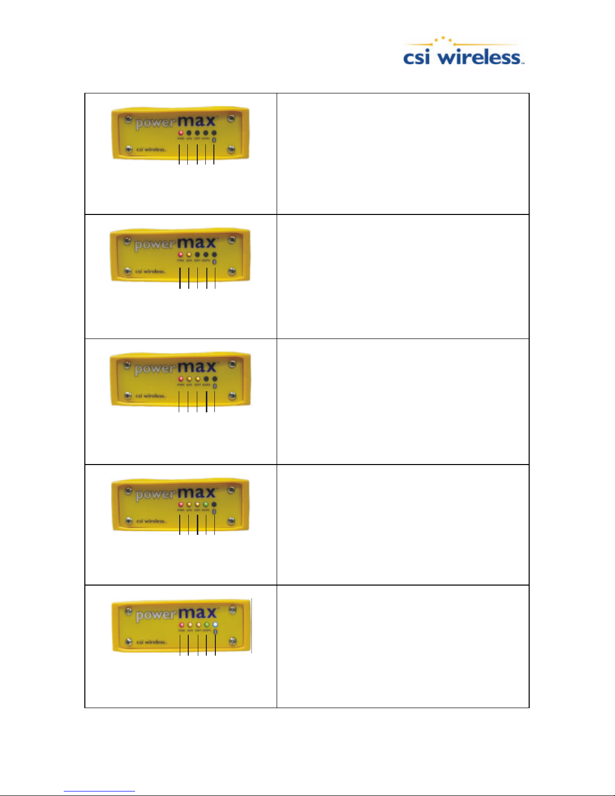
Table 7-2 LED Functions
Differential
Bluetooth
Differential
Bluetooth
Differential
Bluetooth
Differential
Bluetooth
Differential
Bluetooth
DGPS
GPS
Power
DGPS
GPS
Power
DGPS
GPS
Power
Power LED: (red)
This LED should be on solid once power is applied to the receiver. This
is the only LED that is not under computer control.
GPS LED: (Yellow LED closest to Red)
This LED serves two purposes:
At power-on it will blink 3 to 4 times, once per second, and then go off.
If it fails to blink, the Differential processor is likely to have failed. If it
does not stop blinking, the GPS processor is the likely culprit.
After a minute or so, this LED should go on solid yellow to indicate that
GPS has lock. This is true even if differential corrections are not
available. If the LED is continually blinking and you have been
programming your PowerMAX, it is possible it is still in programming
mode. The PowerMAX will not communicate while in this state. Simply
power cycle the PowerMAX to restore normal communications.
Differential LED: (Yellow LED closest to Green)
This LED can be in several states:
§ Off – Differential signal has not been received.
§ Flickering on and off – the receiver is close to acquiring the
differential signal.
§ Blinking at a steady rate - Differential signal has been acquired, but
the Bit-Error-Rate (BER) of the “best” signal tracked is higher than
150.
Generally, this will not affect performance,
but it is a warning of weak signal strength.
§ On Solid –WAAS or beacon signal has been acquired and signal
strength is good.
DGPS LED: (green)
This LED will remain off until a differentially corrected GPS solution is
available. It will blink at a steady rate if the solution has not converged to
the accuracy specified by the $JLIMIT command and will become solid
green after the solution has converged. (The $JLIMIT sets the threshold
GPS
Power
DGPS
for the RMS residual error and this error gives a rough indication of
expected user accuracy. Note, however, that it is not a direct measure
of accuracy. Factors such as constellation geometry must also be taken
into account. The default value for $JLIMIT is 10 meters).
Bluetooth LED: (blue)
This LED will remain off until a Bluetooth connection is established
between the PowerMAX and the other device. It will remain on until the
connection is broken.
DGPS
GPS
Power
PowerMAX User Manual 38
Page 52

Appendix A - Specifications
This appendix provides the operational, mechanical, electrical, physical, and environmental
specifications of the PowerMAX receiver.
Table A-1 PowerMAX Receiver Specifications
Internal GPS Engine Operational Specifications
Item Specification
Frequency 1.575 GHz
Channels 12 parallel tracking
Horizontal accuracy < 1 m 95%
Max Position update rate Up to 5 Hz
Serial Interface Specifications (standard cable)
Item Specification
Serial port interface level RS-232C
Data Port DB9 Socket
Data Port available baud rates 4800, 9600, 19200 and 38400 Baud
Output protocol NMEA 0183, proprietary binary
Input protocol NMEA 0183
External correction input protocol RTCM SC-104
Item Specification
Input voltage 9.5 to 32 VDC
Power consumption <3 W Nominal
Item Specification
Enclosure Powder coated aluminum enclosure
Length 160 mm (6.34”) excluding connectors
Width 137 mm (5.44”)
Height 63 mm (2.5”)
Weight 689 g (1.52 lb)
Item Specification
Storage temperature
Operating temperature
Humidity 95% Non-Condensing
Power Specifications
Mechanical Characteristics
Environmental Specifications
-40°C to 85°C
-30°C to 70°C
Table A-2 MGL-3 Antenna Specifications
Item Specification
Frequency Range, Beacon 283.5 – 325 kHz
LNA Gain, Beacon 34 dB
Frequency Range, GPS 1.575 GHz
LNA Gain, GPS Various Available
PowerMAX User Manual 39
Operational Specifications
Power Specifications
Item Specification
Page 53

Input voltage 4.9 to 13 VDC supplied by receiver
Input current 50 -60 mA
Item Specification
Enclosure PVC Plastic
Length 128 mm (5.06”)
Width 128 mm (5.06”)
Height 84 mm (3.33”)
Weight 450 g (1.0 lb)
Mounting Thread 1-14-UNS-2B
Connector TNC-S
Extension Cable RG-58
Mechanical Characteristics
Item Specification
Storage temperature
Operating temperature
Humidity 100% Condensing
Environmental Specifications
-40°C to 80°C
-30°C to 70°C
PowerMAX User Manual 40
Page 54
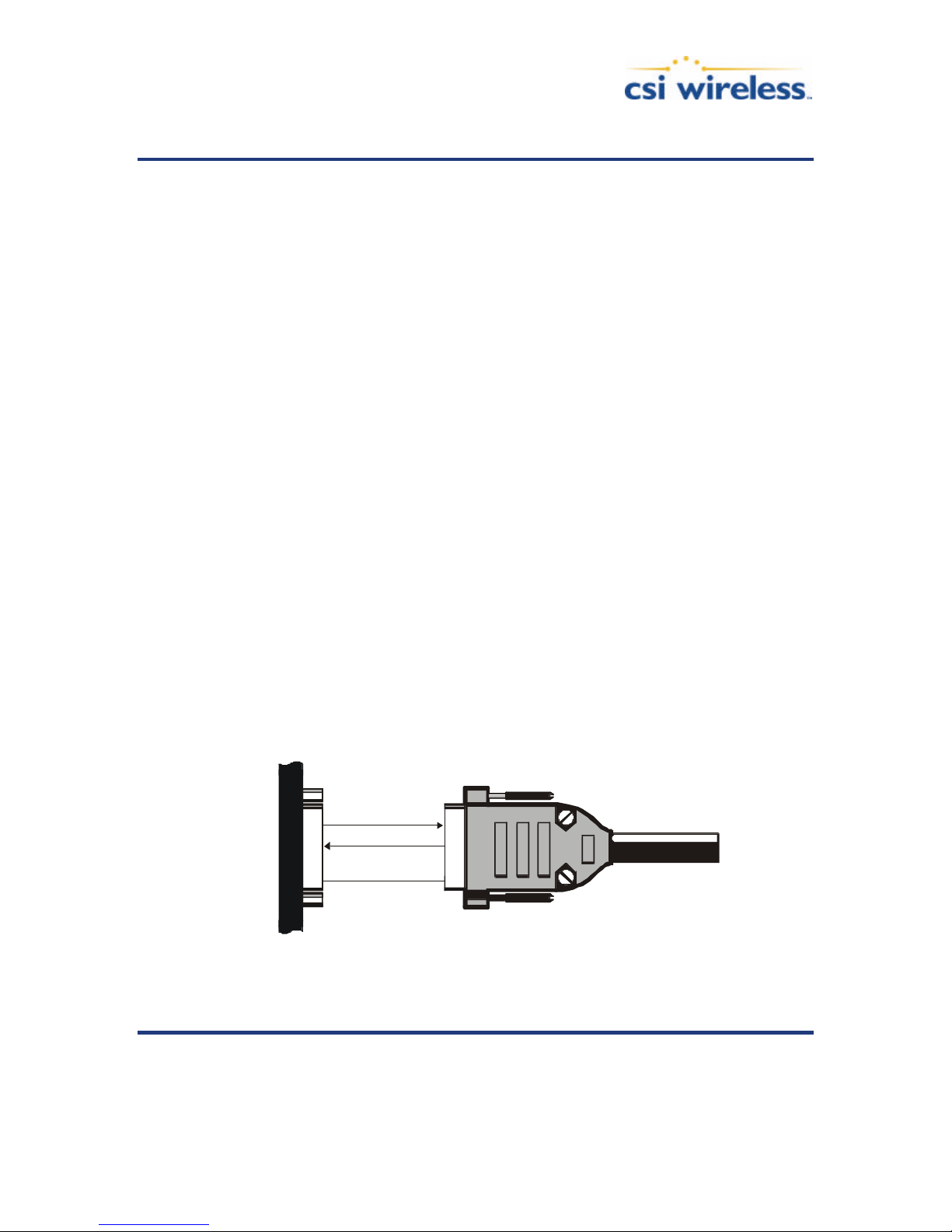
Appendix B – Interface
PowerMAX DATA
This appendix provides infor mation on interfacing the main aspects of your PowerMAX.
The main purpose of the PowerMAX is to provide differentially corrected position and related
information to a data logging or navigation device in the standard NMEA format. In addition to
the PowerMAX operating as a positioning sensor, you may also have a use for the correction
data received by the internal SBAS demodulator.
The following sections detail how to interface your PowerMAX depending on your application.
GPS NMEA Output
When operating the PowerMAX as a differential positioning tool, the data output from either
PowerMAX communication port (Serial or Bluetooth) is NMEA data that provides a variety of
information, such as position, speed, satellites tracked, and more. This is the normal da ta
output and mode of operating the PowerMAX.
To establish communications between the PowerMAX receiver and your data logging or
navigation device in this mode of operation, you must:
• Connect Pin-2 - transmit (TX) of the PowerMAX Serial Port to the receive pin (RX) of the data
logging or navigation device.
• Connect Pin-3 - receive (RX) of the PowerMAX Serial Port to transmit pin (TX) of the other
device if it is able to configure the PowerMAX. Otherwise, this connection is optional.
• Connect Pin-5 - signal ground of the PowerMAX Serial Port to the signal return or of the external
device.
Figure B-1 illustrates the required interface between the PowerMAX and an external device:
External Device
2 TX NMEA
3 RX NMEA TX
5 GND GND
Figure B-1 Serial Interface
RX
Note - For successful communications, the baud rate of the PowerMAX port must
be set to match that of the data logging or monitoring device. The PowerMAX
only supports an RS -232C serial port. Refer to the Programming Manual for
PowerMAX User Manual 41
Page 55
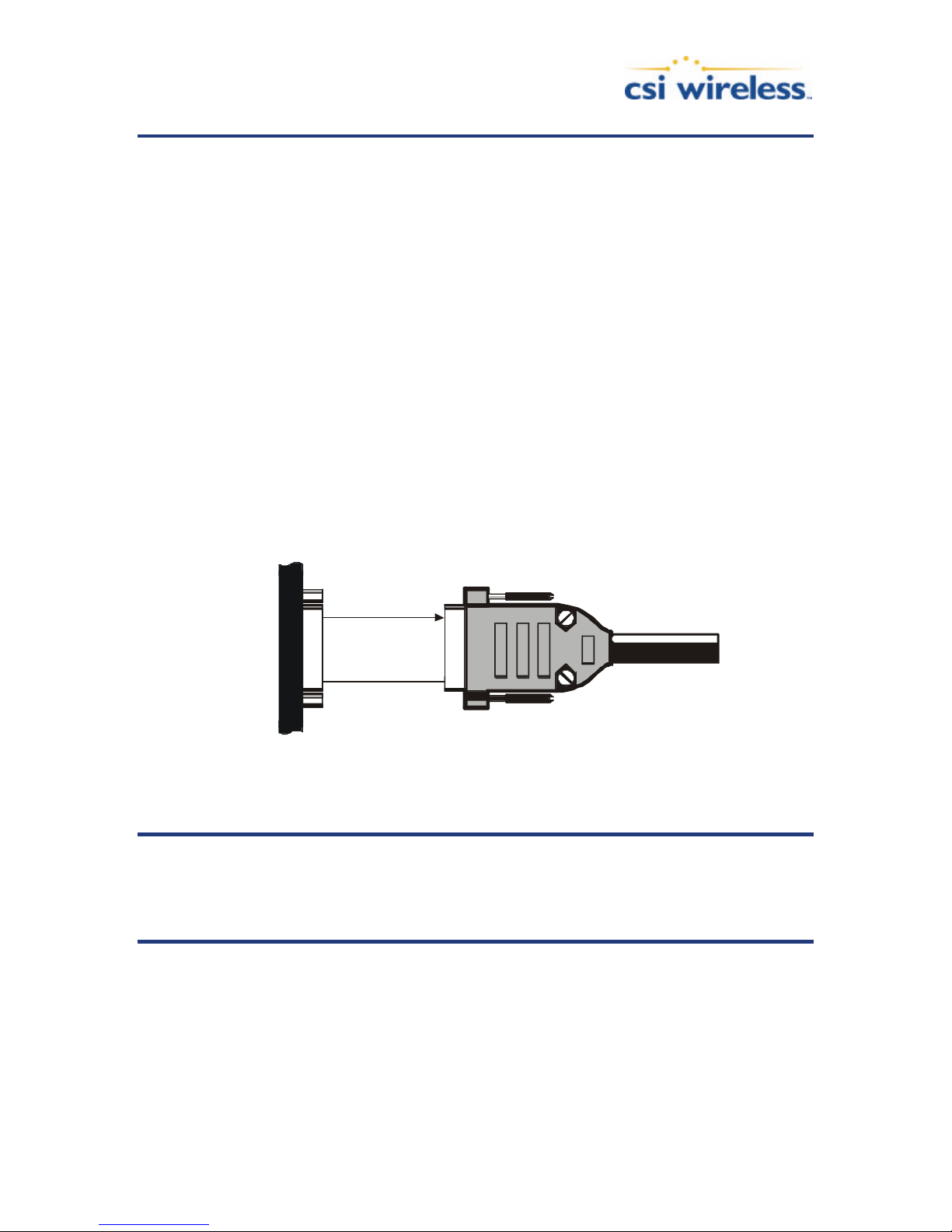
instructions related to setting the PowerMAX baud rate.
PowerMAX DATA
RTCM Data Output
To output only RTCM correction data from the internal SBAS correction source from the Serial
or Bluetooth ports of the PowerMAX, use the following proce dure:
• Turn off all NMEA and binary messages using the $JOFF<CR><LF> command
• Turn RTCM on using the $JRTCM,1<CR><LF> command
To establish communications between the PowerMAX and an external GPS receiver, you must:
• Connect Pin-2-transmit (TX) of the serial port to the receive pin (RX) of the separate GPS
receiver or logging device.
• Connect Pin-5-Common Ground of the serial port to the signal return or common ground of the
separate GPS receiver.
Figure B-2 illustrates the required interface between the PowerMAX and device that receives
position information:
2 TX RTCM
5 GND GND
RX
External Device
Figure B-2 RTCM Data Output From Serial Port
Note - For successful communicatio ns, the baud rate of the PowerMAX Serial port
must be set to match that of the separate GPS receiver. Additionally, you must
interface the PowerMAX to an RS-232C serial port of the separate GPS receiver.
Refer to the Programming Manual for instructions related to setting the
PowerMAX baud rate.
External Correction Input
In this operating mode, an external correction device inputs RTCM correction data through the
Serial port. In order to accomplish this, the PowerMAX must be commanded to use external
corrections using the $JDIFF command.
To configure external correction input on the Serial port you must:
PowerMAX User Manual 42
Page 56
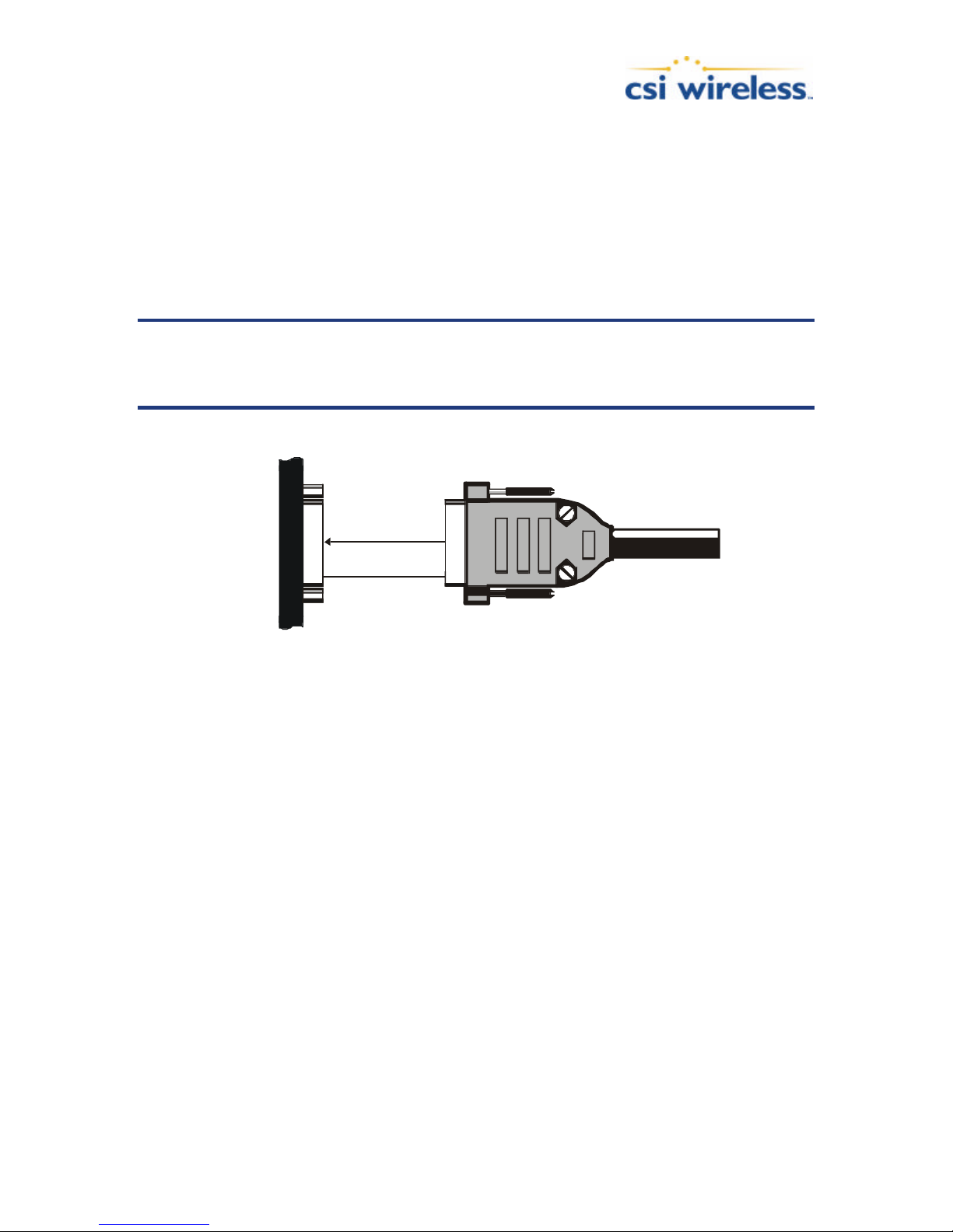
• Communicate with the PowerMAX on the Serial Port. Ensure that the baud rate of the Serial Port
PowerMAX DATA
and the external correction source match by issuing the appropriate $JBAUD command.
• Issue a $JDIFF,THIS<CR><LF> command through the Serial port.
To establish communications between the PowerMAX and an external GPS receiver, you must:
• Connect Pin-3-receive (RX) of the RTCM input port to transmit pin (TX) of the external
correction source
• Connect Pin-5-Common Ground of the RTCM input port to the signal return or common ground
of the external correction source
Note - For successful communications, the baud rate of the PowerMAX differential
port must be set to match that of the external correction source. The correction
source must support an RS-232 interface level and the baud rates between each
device must match.
External Device
3 RX RTCM TX
5 GND GND
Figure B-3 RTCM Data Input to Serial Port
PowerMAX User Manual 43
Page 57

Appendix C – Introduction to GPS,
SBAS and Beacon
This chapter provides a brief overview of GPS, differential GPS, Space Based Augmentation
Systems (SBAS) such as WAAS / EGNOS / MSAS / GAGAN and radiobeacon.
GPS
The United States Department of Defense (DoD) operates a reliable, 24 hour a day, all weather
Global Positioning System (GPS).
Navstar, the original name given to this geographic positioning and navigation tool, includes a
constellation of 24 satellites (plus active spares) orbiting the Earth at an altitude of
approximately 22,000 km.
How it Works
These satellites transmit coded information to GPS users at UHF (1.575 GHz) frequencies that
allows user equipment to calculate a range to each satellite. GPS is essentially a timing system ranges are calculated by timing how long it takes for the coded GPS signal to reach the user’s
GPS antenna.
To calculate a geographic position, the GPS receiver uses a complex algorithm incorporating
satellite coordinates and ranges to each satellite. Reception of any four or more of these signals
allows a GPS receiver to compute 3D coordinates. Tracking of only three satellites reduces the
position fix to 2D coordinates (horizontal with fixed vertical).
The GPS receiver calculates its position with respect to the phase center of the GPS antenna.
The latitude, longitude, and altitude of the antenna are referenced according to the World
Geodetic System 1984 ellipsoid (WGS-84).
GPS Services
The positioning accuracy offered by GPS varies depending upon the type of service and
equipment available. For security reasons, two GPS services exist: the Standard Positioning
Service (SPS) and the Precise Positioning Service (PPS). The SPS uses a code modulated onto
the signal for measurements and is referred to as the Coarse Acquisition code (C/A code). The
US Department of Defense (DoD) reserves the PPS for use by its personnel and authorized
partners. The PPS uses a different code than the SPS, referred to as the Precise Code (P -code)
and contains more resolution than the C/A code. The DoD provides the SPS free of charge,
worldwide, to all civilian users.
In order to maintain a strategic advantage, the US DoD used to artificially degrade the
performance of the SPS so that the positioning accuracy was limited to 100 meters 95% of the
time. This intentional degradation is called Selective Availability (SA). The effect of SA has been
turned to zero since mid-2000, however, it has not been officially ‘turned off’.
PowerMAX User Manual 44
Page 58

Currently, autonomous GPS is able to provide accuracy on the order of 10 meters, depending
on the sophistication of the GPS engine. For many positioning and navigation applications, this
level of accuracy is not sufficient, and differential techniques must be employed.
Differential GPS
The primary sources of errors that degrade GPS performance include SA (currently set to a
zero effect), atmospheric errors, timing errors, satellite orbit errors, and multipath. Differential
GPS (DGPS) is essentially a differencing process that removes sources of error from the GPS
position solution and improves the integrity of the GPS position solution.
There are a number of methods of differential measurement correction:
• Conventional real-time differential – This is the most common form of correcting GPS errors in
real-time with corrections sent to the rover GPS receiver by some form of communications
equipment. Conventional real-time differential uses C/A code range measurements and their
associated corrections. Carrier phase corrections are not used with this form of differential
technique.
• Post processing – This method is often used when either higher accuracy than achievable through
conventional differential is needed, or a conventional form of real-time corrections is not available
in the region where the rover receiver is being operated. Depending on receiver hardware and the
methodology used for post process, performance can be from many centimeters to millimeter
precision. A variety of 3rd party software packages are available to post process GPS raw
measurement data. The PowerMAX can be configured to output raw measurement data at rates
of up to 5 Hz in a proprietary format. This data can be converted to an industry standard RINEX
format if needed.
• Real-Time Kinematic – This method uses more sophisticated techniques to resolve the number of
wavelengths between the satellite and the user, to provide centimeter -level positioning (or better)
in real-time. This technique uses high-end receiver hardware, antennas, and internal operating
software to compute accurate position solutions. The compromise with this method of differential
correction is increased system complexity, cost, and operating constraints.
The PowerMAX includes two primary sources of conventional real-time corrections – beacon
DGPS and Space -Based Augmentation System (SBAS). External corrections may also be input to
the PowerMAX for situations where either internal correction services is not available or an
external source is preferential.
In addition to the conventional differential positioning with internal sources of corrections, the
PowerMAX also has a documented binary raw measurement protocol. A RINEX translator is
available from CSI Wireless in the event that this may be useful, in addition to some C code
snippets to aid in integrating the binary format itself into your own application.
For heading determination, the PowerMAX uses a moving base station RTK solution. This
allows for a very precise computation of heading regardless of whether or not the receiver is in
differential mode using either internal source of corrections or those from an external source.
Conventional Real -Time Differential
The majority of GPS navigation and positioning uses this form of positioning. Conventional realtime differential techniques are more robust in their usage and versatility than post processing
or RTK solutions. They are tolerant to errors in communication of the real-time corrections
PowerMAX User Manual 45
Page 59

from the base station or correction network, provide a reasonable amount of accuracy (submeter accuracy is best-case), and can be simply turned on and used without too much regard
other than ensuring a lock to GPS satellite signals and the correction communication link.
How it Works
Conventional DGPS involves setting up a reference GPS receiver at a point of known
coordinates. This receiver makes distance measurements, in real-time, to each of the GPS
satellites. The measured ranges include the errors present in the system. The base station
receiver calculates what the true range, without errors, knowing its coordinates and those of
each satellite. The difference between the known and measured range for each satellite is the
range error. This error is the amount that needs to be removed from each satellite distance
measurement in order to correct for errors present in the system.
The base station transmits the range error corrections to remote receivers in real-time. The
remote receiver corrects its satellite range measurements using these differential corrections,
yielding a much more accurate position. This is the predominant DGPS strategy used for a
majority of real-time applications. Positioning using corrections generated by DGPS
radiobeacons will provide a horizontal accuracy of 1 to 5 meters with a 95% confidence. More
sophisticated, short -range DGPS systems (10 to 15 km) can achieve centimeter-level accuracy,
but are expensive and often limited to precise survey applications due to technical constraints
on their use.
DGPS Format
For manufacturers of GPS equipment, commonality is essential to maximi ze the utility and
compatibility of a product. The governing standard associated with GPS is the Interface Control
Document, ICD -GPS-200, maintained by the US DoD. This document provides the message
and signal structure information required to access GPS.
Like GPS, DGPS data and broadcast standards exist to ensure compatibility between DGPS
services and associated hardware and software. The Radio Technical Commission for Maritime
Services Special Committee 104 has developed the primary DGPS standard associated with
conventional DGPS, designated RTCM SC -104 V2.2. This correction standard is used by many
correction services, including many private reference stations and DGPS beacon systems. The
PowerMAX supports this correction protocol via either of its two serial ports.
In addition to the RTCM standard, the Radio Technical Commission for Aeronautics has a
differential service intended for wide area correction services, designated RTCM SC-159. The
United States Federal Aviation Administration’s Wide Area Augmentation System (WAAS) and
other compatible Space Based Augmentation Systems (SBAS) such as the European
Geostationary Navigation Overlay System (EGNOS) and the Japanese MT-SAT Satellite-based
Augmentation System (MSAS) use this data format. The PowerMAX receiver is compatible with
each of these differential services.
Note – When using a differential correction service, the resultant position may be
referenced to a local datum rather than the WGS-84 ellipsoid. Please refer to your
signal provider for more information.
PowerMAX User Manual 46
Page 60

Post Processing
Post processing is a method to compute accurate positions in post mission by logging raw
measurement data at the base station and the rover simultaneously. The differential processing
can then be performed later in the office using sophisticated processing software tools. There
are a small variety of methodologies available to the operator, such as static, rapid static,
kinematic, etc.
Describing in detail the various post processing techniques is beyond the scope of this
document, however, generally, post processing is more complicated from a procedural
perspective and requires more skill to successfully operate than real-time systems.
Factors Affecting DGPS Accuracy
Many factors affect the positioning accuracy that a user may expect from a DGPS system. The
most significant of these influences include:
• Proximity of the remote user to the reference station (atmospheric and orbit errors)
• Age of the received differential corrections
• Atmospheric conditions at the beacon and remote user locations
• Satellite constellation geometry, often expressed as a Dilution of Precision (DOP)
• Magnitude of GPS signal multipath present at the remote station
• Quality of the GPS receiver being used at both the reference and remote stations
Proximity of the Reference Station
The distance between a remote user and the reference station can sometimes be considerable,
such as when using 300 kHz DGPS radiobeacons. Consequently, some of the errors associated
with GPS at the base station differ somewhat from those at the remote user’s location. This
spatial decorrelation of errors can result in a relative position offset from the absolute
coordinates of the remote receiver. This offset may be as much as one meter for every 100 km
(62 miles) between the base station and remote receiver.
The causes of decorrelation are:
• GPS satellite orbit errors (significant)
• Ionospheric errors (potential to be most significant depending on level of activity)
• Tropospheric errors (less significant)
GPS satellite orbit errors are typically a greater problem with local area differential systems,
such as that of radiobeacons. The decorrelation effect is such that the satellite’s orbit error
projects onto the reference receiver and remote receiver’s range measurements differently. As
the separation between the receivers increases, the orbit error will not project onto the ranges
in the same manner, and will then not cancel out of the measurement differencing process
completely. SBAS networks, with the use of multiple base stations, are able to accurately
compute the orbit vector of each satellite. The resulting corrector is geographically
independent, so minimal decorrelation occurs with respect to position within the network.
The ionosphere and the troposphere both induce measurement errors on the signals being
PowerMAX User Manual 47
Page 61

received from GPS. The troposphere is the humid portion of the atmosphere closest to t he
ground. Due to it humidity, refraction of GPS signals at lower elevations can distort the
measurements to satellites. This error source is rather easily modeled within the GPS receiver
and doesn’t constitute a significant problem.
The error induced by the ionosphere is more significant, however, is not as simple a task to
correct. The ionosphere is charged layer of the atmosphere responsible for the Northern
Lights. Charged particles from the sun ionize this portion of the atmosphere, resulting in an
electrically active atmospheric layer. This charged activity affects the GPS signals that penetrate
this layer, affecting the measured ranges. The difficulty in removing the effect of the ionosphere
is that it varies from day to day, and even hour to hour due to the sun’s 11 -year solar cycle and
the rotation of the earth, respectively. During the summer of 2001, the sun’s solar cycle
reached an 11-year high and going forward we will see a general cooling trend of the ionosphere
over the next few years thus reducing ionospheric activity.
Removing the effect of the ionosphere depends on the architecture of the differential network.
DGPS radiobeacons, for example, use a more conventional approach that WAAS or SBAS in
general. DGPS beacons make use of a single reference station, which provides real-time GPS
error corrections based upon measurements that it makes at its location. It’s possible that the
state of the ionosphere differs between the remote user and the single reference station. This
can lead to incompletely corrected error source that could degrade positioning accuracy with
increased distance from the base station.
WAAS and SBAS use a different approach, using a network of reference stations in strategic
locations to take measurements and model the real-time ionosphere. Updates the ionospheric
map are sent on a continual basis to ensure that as the activity of the ionosphere changes with
time, the user’s positioning accuracy will be maintained. Compared to using a DGPS beacon,
the effect of geographic proximity to a single reference station is minimized resulting in more
consistent system performance throughout all locations within the network.
Correction Latency
The latency of differential corrections to a lesser extent affects the achievable positioning
accuracy at the remote receiver since the magnitude of SA was turned to zero in year 2000.
Latency is a function of the following:
• The time it takes the base station to calculate corrections
• The data rate of the radio link
• The time it takes the signal to reach the user
• The time required for the remote differential receiver to demodulate the signal and communicate it
to the GPS receiver.
• Any data loss that occurs through reception problems
Most of these delays require less than a second, though in some instances, depending upon the
amount of information being transferred, overall delays of three to five seconds may occur. The
effect of latency is mitigated by new COAST technology within the PowerMAX. This
technology is especially valuable in conditions of DGPS signal loss where the age of corrections
increases for each second of signal loss. Consult Section 1.7 for further information on COAST.
Satellite Constellation Geometry
PowerMAX User Manual 48
Page 62

The number of satellites visible and their geometry in the sky influences positioning accuracy.
The Dilution of Precision (DOP) describes the strength of location and number of satellites in
view of the receiver. A low DOP indicates a strong potential for better accuracy than a high
DOP. Generally, more satellites visible to both the reference and remote receivers will provide
a lower DOP (any satellites seen by one receiver and not the other, are not used in the position
solution). Additionally, if the satellites are evenly spread around the receiver, rather than
grouped in a few regions of the sky, a lower DOP (stronger solution) will result.
GPS Signal Multipath
Satellite signals received by the GPS receiver by a reflection from an object can decrease
positioning accuracy. These multipath signals increase the measured range to a satellite as the
signal takes a longer route to the GPS antenna. Certain precautions will minimize GPS antenna
sensitivity to these reflected signals. Operating away from large reflective structures such as
buildings or using special antennas and GPS equipment can help to reduce the impact of
multipath. For most consumer-level applications, a small amount of multipath is tolerable.
GPS Receiver Quality
The quality of a GPS receiver has a dramatic influence on positioning accuracy. Consumerbased GPS products, such as many affordable handheld and fixed-mount receivers, typically
operate wi th an accuracy of 3 to 5 meters horizontally 95% of the time. The accuracy of a
particular product depends on the specific receiver’s performance characteristics. Higher
accuracy GPS receivers are able to achieve sub-1 meter horizontal accuracy 95% of the time
using real-time DGPS transmissions. The PowerMAX falls in to this latter category.
Space Based Augmentation Systems
The US Federal Aviation Administration is in the process of developing a Wide Area
Augmentation System (WAAS) for the purpose of providing accurate positioning to the aviation
industry. In addition to providing a high quality, accurate service for this industry, this service is
available free of charge to all other civilian users and markets in North America. This service
falls into the greater category of Space Based Augmentation System (SBAS).
Upon the successful completion of a 21-day test on August 24, 2000, the FAA announced that
WAAS would be running 24 hours per day, seven days per week from then on. Testing has
shown since that this signal is accurate and reliable, however, since no official statement on it’s
Initial Operating Capability has been issued, this signal is to used at your risk.
Other government agencies are in the process of developing compatible SBAS systems fo r their
respective geographic regions. In Europe, the European Space Agency, the European
Commission, and EUROCONTROL are jointly developing the European Geostationary Overlay
System (EGNOS). In Japan, the MTSAT Satellite-based Augmentation System (MSAS) is in
progress of development by the Japan Civil Aviation Bureau (JCAB). China has a similar
program for a SBAS and the service is named the Chinese Satellite Navigation Augmentation
System (SNAS). The PowerMAX is capable of receiving correction data from all compatible
SBAS.
EGNOS is currently in a prototyping phase, referred to as the EGNOS System Test Bed (ESTB)
and which has been broadcasting a test signal since February 2000. EGNOS should be used at
PowerMAX User Manual 49
Page 63

your risk only. MSAS has yet to begin transmitting data publicly. SNAS is transmitting
correction data currently on a military communication channel and is expected to become
publicly available in the near future.
Warning – Although WAAS has successfully passed a 21-day test, and is publicly
available; its use is at your risk and discretion. EGNOS is not currently
broadcasting with any form of certification or approval. It may produce misleading
information, and its use is entirely at your risk and discretion.
MSAS may begin broadcasting a preliminary signal as early as the end of 2002.
How it Works
A SBAS incorporates a modular architecture, similar to GPS, comprised of a Ground Segment,
Space Segment, and User Segment:
• The Ground Segment includes reference stations, processing centers, a communication network,
and Navigation Land Earth Stations (NELS)
• The Space Segment includes geostationary satellites (For example, WAAS and EGNOS use
Inmarsat-III transponders).
• The user segment consists of the user equipment, such as a PowerMAX receiver and antenna
A SBAS uses a state-based approach in their software architecture. This means that a separate
correction is made available for each error source rather than the sum effect of errors on the
user equipment’s range measurements. This more effectively manages the issue of spatial
decorrelation than some other techniques, resulting in a more consistent system performance
regardless of geographic location with respect to reference stations.
Specifically, SBAS calculates separate errors for the following:
• The ionospheric error
• GPS satellite timing errors
• GPS satellite orbit errors
Provided that a GPS satellite is available to the SBAS reference station network for tracking
purposes, orbit and timing error corrections will be available for that satellite. Iono spheric
corrections for that satellite are only available if the signal passes through the ionospheric map
provided by SBAS (for example, the WAAS ionospheric map covers the majority of North
America). As an example, if a satellite is South of your current location at a low elevation angle,
the pierce point of the ionosphere will be considerably South of your location since the
ionosphere is at an altitude of approximately 60 km. There must be sufficient ionospheric map
coverage beyond your location in order to have ionospheric correctors for all satellites.
To enhance the information provided by SBAS, the PowerMAX extrapolates the ionospheric
information beyond the broadcast information. This increases the usable geography for WAAS
and is discussed in Section 1.5.5. This feature helps to improve the usable coverage area of a
SBAS service.
PowerMAX User Manual 50
Page 64

Signal Information
A SBAS transmits correction data on the same frequency as GPS from a geostationary satellite
(the space segment), allowing the use of the same receiver equipment used for GPS. Another
advantage of having SBAS transmit on the same frequency is that only one antenna is required.
Reception
Since SBAS broadcast in the L-band, the signal requires a line of sight in the same manner as GPS
to maintain signal acquisition.
Currently, two commercial marine communication satellites are transmitting WAAS data for
public use, and one each is located above both the Pacific Ocean and Northern Brazil. Due to
their location, these satellites may appear lower on the horizon, depending on your geographic
position on land. In regions where the satellites appear lower on the horizon, they may be
more prone to being masked by terrain, foliage, buildings or objects, resulting in signal loss. The
further that you are away from the equator and the satellite’s longitude will cause the satellite to
appear lower on the horizon. Fortunately, the CSI Wireless COAST Technology helps alleviate
this problem by maintaining system performance when WAAS (SBAS) signal loss occurs for
extended periods of time. More information on COAST is provided in Section 1.7.
The EGNOS System Test Bed (ESTB), also referred to as EGNOS in this document, uses two
geostationary satellites (separate from WAAS), however, in this case, they are located over the
Atlantic and Indian Oceans. Similar to WAAS, the satellites may appear lower on the horizon,
depending on your geographic position on land. The further that you are away from the
equator and the satellite’s longitude will cause the satellite to appear lower on the horizon. If
the EGNOS signal becomes unavailable due to obstruction, COAST technology helps to
maintain system performance during times of differential outage.
When using SBAS correction data, the PowerMAX is able to provide you with the azimuth and
elevation of the SBAS available satellites via a NMEA serial port command to aid in determining
their position with respect to the built-in antenna. More about this feature is described in
Section 5.5.2.
WAAS and ESTB Coverage
Figure C-1 depicts the current WAAS coverage as provided by the currently leased Inmarsat
Atlantic Ocean Region - West (AOR-W) and Pacific Ocean Region (POR) geostationary
satellites. This figure approximates signal coverage with white shading where each satellite is 5°
elevation or greater. Figure C-1 also shows additional contours for 10°, 15°, and 20° elevations.
Within the white shaded coverage area, at least one of the two satellites is available by line of
sight. Within the overlap area, both satellites may be accessible. Although there is geographic
coverage at higher latitudes, practical usage of WAAS will be limited to environments where a
relatively consistent line of sight to either of the Inmarsat satellites from the PowerMAX system.
Figure C-2 presents approximate EGNOS System Test Bed coverage provided by the leased
Inmarsat Atlantic Ocean Region - East (AOR-E) and Indian Ocean Region (IOR) satellites. This
figure approximates signal coverage with white shading where each satellite is 5° elevation or
greater. Figure C-2 also shows additional contours for 10°, 15°, and 20° elevations. Within the
white shaded coverage area, at least one of the two satellites is available by line of sight. Within
PowerMAX User Manual 51
Page 65
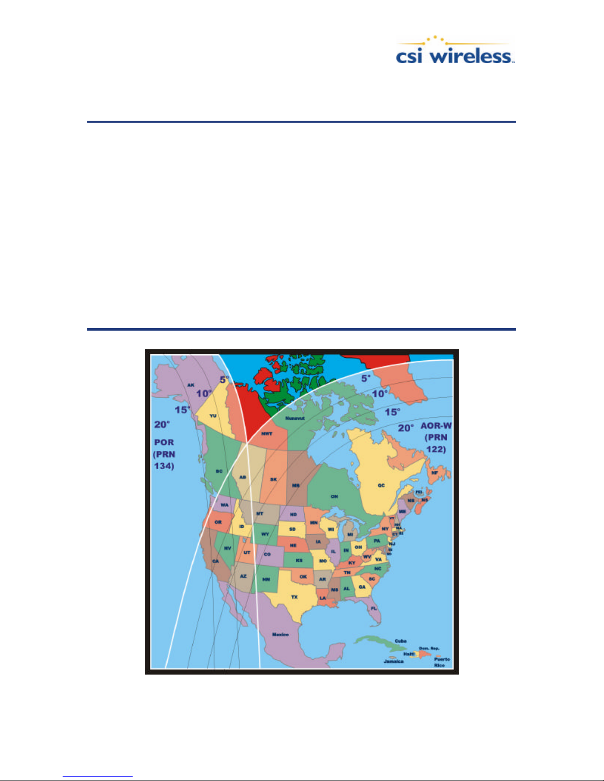
the overlap area, both satellites may be accessible. Virtually all of Europe, part of northern
Africa, and into the Middle East is covered with at least one signal. Most of Europe is covered
by two signals.
Note - Currently, we recommend using only the AOR-E satellite (prn 120) and the
IOR-W satellite (prn 126). Refer to Appendix D – Resources for information on
how to monitor the status of the ESTB.
Note - The satellite elevation angle lowers with increasing distance away from the
equator and from the satellite’s longitude. Although a good amount of signal
coverage is shown in Northern latitudes for both WAAS and EGNOS, it may not be
usable due to its low elevation angle and the potential for it to be obstructed.
Ideally, testing of the system in the area of its use is recommended to ensure that
the signal is sufficiently available.
Note - The SBAS signal coverage may be present in some areas without either
sufficient ionospheric map coverage or satellites with valid orbit and clock
correctors. In such a case, differential positioning with SBAS may not be desirable
or possible, as four or greater satellites (with correctors) must be available to
compute a DGPS position. The next section provides further information on the
ionospheric map features of SBAS and the PowerMAX receiver.
PowerMAX User Manual 52
Figure C-1 WAAS Coverage
Page 66

SBAS Ionospheric Map Extrapolation
To improve upon the ionospheric map provided by SBAS, the PowerMAX receiver extrapolates
a larger ionospheric map from the broadcast coverage map, extending its effective coverage.
This allows the PowerMAX to be used successfully in regions that competitive products may
not.
For WAAS, this is especially important in Canada for regions north of approximately 54 ° N
latitude and east of 110° W longitude. Extrapolation also provides enhanced coverage
throughout much of the Gulf of Mexico.
Please note that the process of estimating ionospheric corrections beyond the WAAS broadcast
PowerMAX User Manual 53
Figure C-2 EGNOS Coverage
Page 67
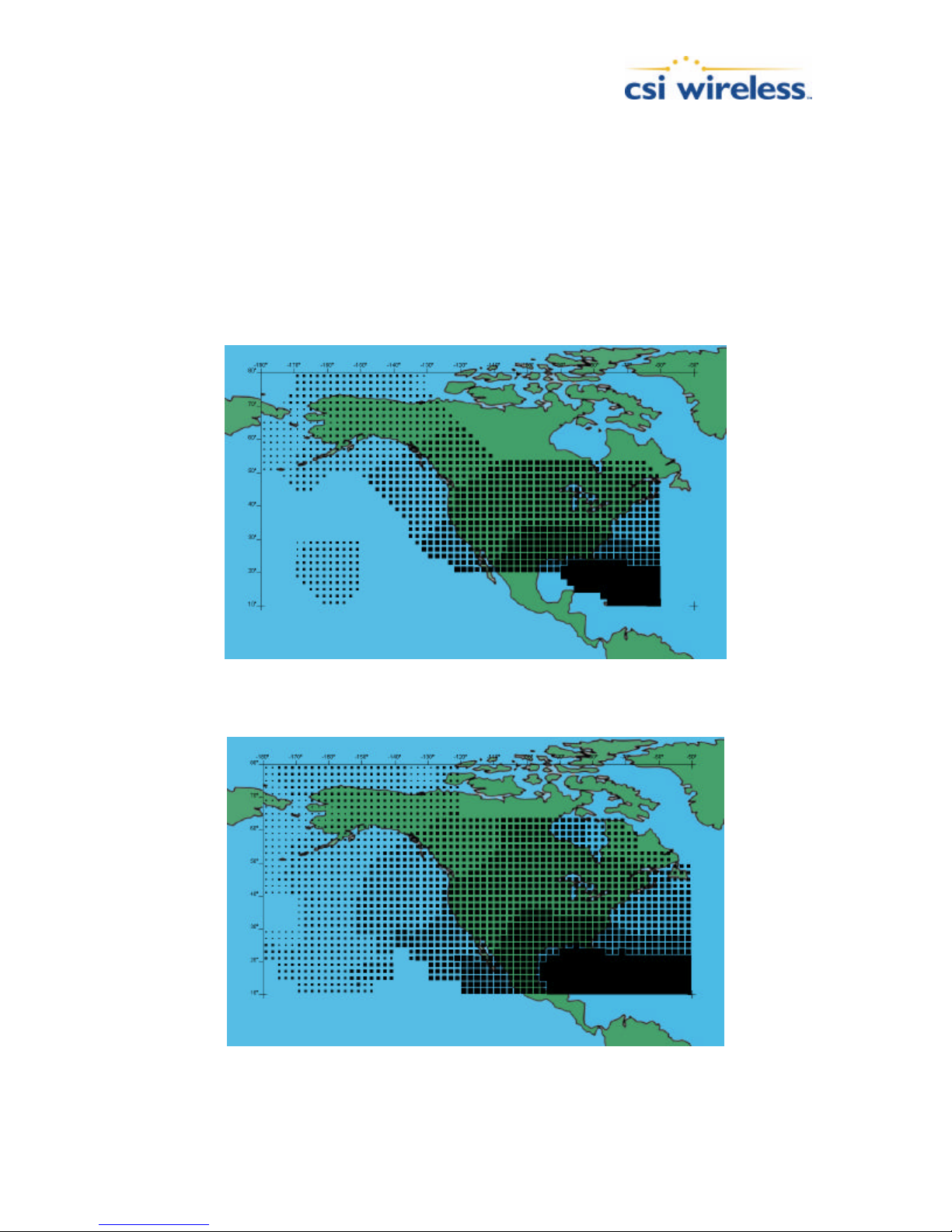
map would not be as good as having an extended WAAS map in the first place. This difference
may lead to minor accuracy degradation.
Figures C-3 and C-4 depict the broadcast WAAS ionospheric map extent and the CSI Wireless
extrapolated version, respectively. As can be seen from Figure C-3, the coverage compared to
Figure C-1 extends further in all directions, enhancing usable coverage.
Similar to the WAAS ionospheric map extrapolation, Figures C-5 and C-6 depict the broadcast
EGNOS ionospheric map extent and the CSI Wireless extrapolated version, respectively. As
can be seen from Figure C-6, the coverage compared to Figure C-5 extends further in all
directions, enhancing usable coverage.
Figure C-3 Broadcast WAAS Ionospheric Correction Map
Figure C-4 Extrapolated WAAS Ionospheric Correction Map
PowerMAX User Manual 54
Page 68
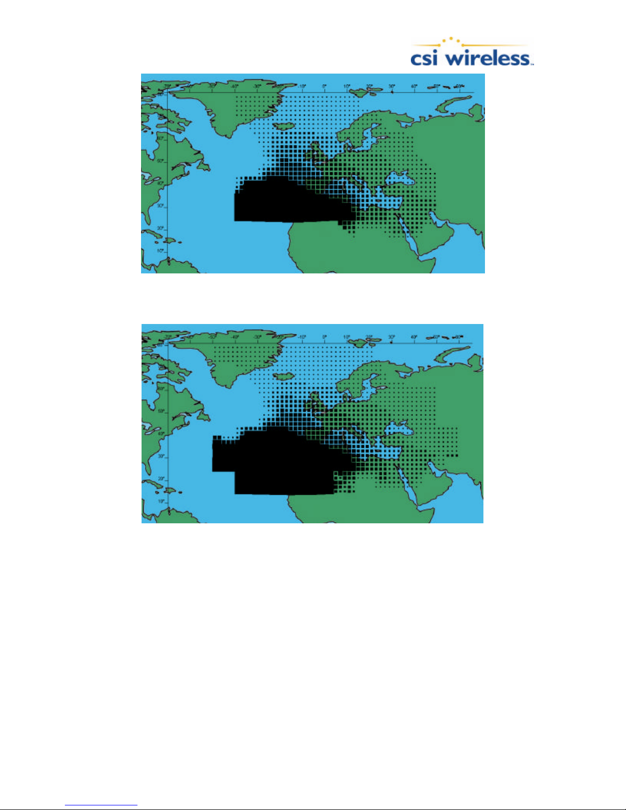
Figure C-5 Broadcast EGNOS Ionospheric Correction Map
Figure C-6 Extrapolated EGNOS Ionospheric Correction Map
Radiobeacon DGPS
Radiobeacon Range
The broadcasting range of a 300 kHz beacon is dependent upon a number of factors including
transmission power, free space loss, ionospheric state, surface conductivity, ambient noise, and
atmospheric losses.
The strength of a signal decreases with distance from the transmitting station, due in large part
to spreading loss. This loss is a result of the signal’s power being distributed over an increasing
surface area as the signal radiates away from the transmitting antenna.
PowerMAX User Manual 55
Page 69

The expected range of a broadcast also depends upon the conductivity of the surface over
which it travels. A signa l will propagate further over a surface with high conductivity than over a
surface with low conductivity. Lower conductivity surfaces such as dry, infertile soil absorb the
power of the transmission more than higher conductivity surfaces, such as sea water or arable
land.
A radiobeacon transmission has three components: a direct line of sight wave, a ground wave,
and a sky wave. The line of sight wave is not significant beyond visual range of the transmitting
tower, and does not have a substantial impact upon signal reception.
The ground wave portion of the signal propagates along the surface of the earth, losing strength
due to spreading loss, atmospheric refraction and diffraction, and attenuation by the surface
over which it travels (dependent upon condu ctivity).
The portion of the beacon signal broadcast skywards is known as the sky wave. Depending on
its reflectance, the sky wave may bounce off the ionosphere and back to Earth causing reception
of the ground wave to fade. Fading occurs when the ground and sky waves interfere with each
other. The effect of fading is that reception may fade in and out. However, this problem usually
occurs in the evening when the ionosphere becomes more reflective and usually on the edge of
coverage areas. Fading is no t usually an issue with overlapping coverage areas of beacons and
their large overall range.
Atmospheric attenuation plays a minor part in signal transmission range, as it absorbs and
scatters the signal. This type of loss is the least significant of those described.
Radiobeacon Reception
Various sources of noise affect beacon reception, and include:
n Engine noise
n Alternator noise
n Noise from Power lines
n DC to AC inverting equipment
n Electric devices such as CRT’s electric motors, and solenoids
Noise generated by this type of equipment can mask the beacon signal, reducing or impairing
reception.
Radiobeacon Coverage
The Figure below shows the approximate radiobeacon coverage throughout the world. In this
figure, light shaded regions note current coverage, with beacon stations symbolized as white
circles.
PowerMAX User Manual 56
Page 70
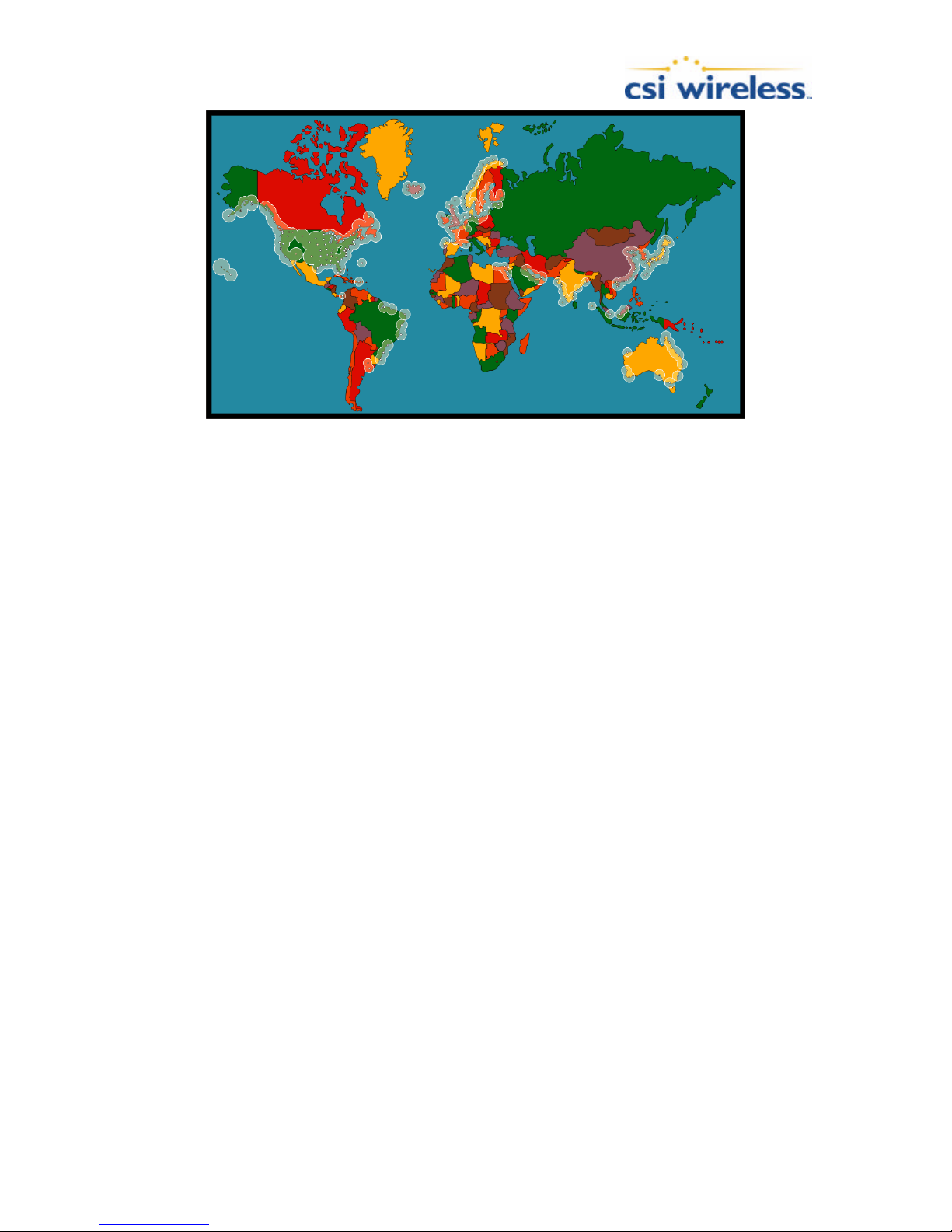
Figure C-7 World DGPS Radiobeacon Coverage
The world beacon networks continue to expand. For more current coverage, consult the CSI
Wireless Web site at www.csi-wireless.com.
PowerMAX User Manual 57
Page 71

Appendix D – Resources
Reference Documents
National Marine Electronics Association, National Marine Electronics Association (NMEA 0183)
Standard for Interfacing Marine Electronic Devices, Version 2.1, October 15, NMEA 1995, PO
Box 50040, Mobile Alabama, 36605 USA, Tel: +1-205-473-1793, Fax: +1 -205-473-1669
Radio Technical Commission for Maritime Services, RTCM Recommended Standards for
Differential NAVSTAR GPS Service , Version 2.2, Developed by Special Committee No. 104,
RTCM 1998, 1800 Diagonal Rd, Suite 600, Alexandria, VA, 22314-2840 USA, Tel: +1-703-6844481, Fax: +1-703-836-4429
Radio Technical Commission for Aeronautics, Minimum Operational Performance Standards
(MOPS) for Global Positioning System/Wide Area Augmentation System Airborne Equipment,
Document RTCA DO-229A, Special Committee No. 159, RTCA 1998, 1828 L Street, NW,
Suite 805, Washington, DC, 20036 USA, Tel: +1-202-833-9339
ARIC Research Corporation, Interface Control Document, Navstar GPS Space Segment /
Navigation User Interfaces, ICD-GPS-200, April 12, 2000, 2250 E. Imperial Highway, Suite 450,
El Segundo, CA 90245-3509, www.navcen.uscg.gov/gps/geninfo/default.htm
CSI Web Site
This following address is the CSI Wireless Web site whi ch provides detailed information on all
products offered by CSI Wireless.
www.csi-wireless.com
FAA WAAS Web Site
This site offers general information on the WAAS service provided by the U.S. FAA.
gps.faa.gov/Programs/WAAS/waas.htm
ESA EGNOS System Test Bed Web Site
This site contains information relating to past performance, real-time performance, and
broadcast schedule of EGNOS www.esa.int/export/esaEG/estb.html
Solar and Ionospheric Activity Web Sites
The following sites are useful in providing details regarding solar and ionospheric activity.
PowerMAX User Manual 58
iono.jpl.nasa.gov//latest.html
iono.jpl.nasa.gov//gim_dailymovie.html
Page 72

www.spaceweather.com
http://www.n3kl.org/sun/noaa.html
PowerMAX User Manual 59
Page 73

Index
$
$GPGGA, 23
$GPGLL, 24
$GPGSA, 24
$GPGST, 25
$GPGSV, 25
$GPRMC, 26
$GPRRE, 26
$GPVTG, 27
$GPZDA, 27, 28
G
Global Search (beacon), 7
GPS, 46
GPS Performance, 9
H
Humidity, 12
I
A
Accuracy, 47, 49
B
Background Search (beacon), 8
Baud Rate, 14, 41, 42, 43
Beacon
Receiver Performance, 8
Beacon Receiver
Signal to Noise Ratio (SNR), 8
Bit Error Rate (WAAS), 6
Bluetooth Connectivity, 14
C
Cable Interface, 2, 11
Cables
Power, 13
Routing and Securing, 11
COAST Feature, 8
Connectivity, 13, 41, 42, 43
Customer Service, xii
D
Default NMEA Message Output, 3, 15
Default Parameters, 4, 15
DGPS Errors, 47
Age of Correction, 48
Geometry, 49
Latency, 48
Multipath, 49
Proximity, 47
Differential Corrections, 46
Differential GPS (DGPS), 46
ICD-GPS-200, 46
Installation
Connecting to External Devices, 13, 14
Environmental Considerations, 12
Placement, 12
Power Considerations, 12
L
LED Indicators, 15
M
Multipath, 49
N
NMEA 0183, 17, 22
NMEA 0183 messages, 22
P
Port Defaults, 15
Positioning Accuracy, 5
Post Processing, 8
Power Cable Fuse, 13
R
RTCM SC-104, 46
S
SBAS Performance, 6
Selective Availability (SA), 45
Serial Port Defaults, 3
Serial Port Pin-out, 4, 14
Signal to Noise Ratio (SNR), 8
PowerMAX User Manual 60
Page 74

T
Temperature, 12
Troubleshooting, 37
Tune Mode
Automatic Beacon Search (ABS), 7, 8
Manual, 8
WAAS Automatic Tracking, 6
U
Update Rates, 6
W
WAAS
Bit Error Rate, 6
Receiver Performance, 6
WGS-84, 44
www.csi-wireless.com, xiii
PowerMAX User Manual 61
 Loading...