

CSI IF10-S2, IF20-S2, IF25-S2, IF15-S2, greensand plus IF10-S2 Installation & Operation Manual
...Page 1
SIGNATURE 2 SERIES
Greensand Plus
Iron Filter Manual
Installation / Operation
Manual
Page 2

SIGNATURE 2 SERIES
Filter Specifications.....................................................................................................................Page 2
Installation...................................................................................................................................Page 3
Control Start-Up Procedures.......................................................................................................Page 8
Utilizing Bluetooth.......................................................................................................................Page 11
Master Programming...................................................................................................................Page 12
Powerhead Assembly..................................................................................................................Page 13
Valve Body Assembly..................................................................................................................Page 14
Bypass Assembly.........................................................................................................................Page 15
Additional Information..................................................................................................................Page 16
Troubleshooting...........................................................................................................................Page 20
Error Codes..................................................................................................................................Page 20
Page 3
SIGNATURE 2 SERIES
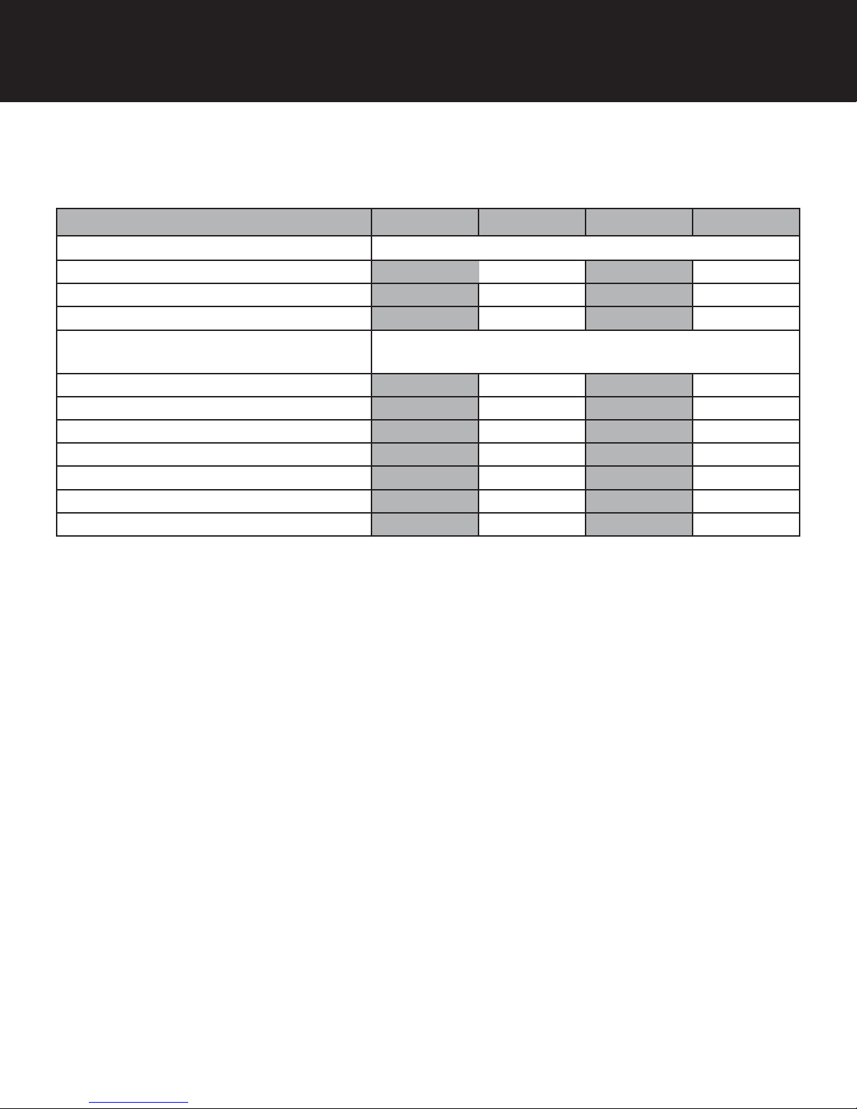
Specifications
General Specifications
Filter Media
Filter Media Capacity (cu ft)
Garnet Sand Underbed (lbs)
Mineral Tank (Vortech ™)
Potassium Permanganate Solution Tank
Size
Removal Capacities Iron / Sulfur
Service Flow Rate - Continous (gpm)
Service Flow Rate - Intermittent (gpm)
Backwash Flow Rate (gpm)
Gallons Used / Regeneration
Space Required
Approximate Shipping Weight (lbs)
IF10-S2 IF15-S2 IF20-S2 IF25-S2
Greensand Plus ™
1.00 1.50 2.00 2.50
20 30 50 50
9 x 48 10 x 54 12 x 52 13 x 54
10 x 16
10 ppm / 3 ppm 10 ppm / 3 ppm 10 ppm / 3 ppm 10 ppm / 3 ppm
4 5 6 8
6 7 8 10
5.0 5.0 6.0 7.0
128 130 173 193
9 x 21 x 57 10 x 22 x 62 13 x 24 x 60 12 x 25 x 62
157 215 305 362
Do NOT use Vaseline, oils, hydrocarbon lubricants or spray silicone anywhere! Petroleum base lubricants will cause
swelling of o-rings and seals. The use of other lubricants may attack plastic Noryl®. It is recommended that Dow Corning® silicone grease be used as a lubricant for all control valves. Dow Corning® 7 Release Compound is used in the
manufacture of Chandler Systems control valves. (Part # LT-150)
Pipe dope and liquid thread sealers may contain a carrier that attacks some plastic materials. It is recommended that
Teflon® tape be used to seal plastic Noryl® threaded fittings.
WARNING
Lubricants
Sealants
2
Page 4

SIGNATURE 2 SERIES
Installation
Greensand Plus Iron Filter is capable of removing dissolved iron, manganese and hydrogen sulfide from water through
oxidation and filtration. The maximum practical limit of iron (Fe) and / manganese (Mn) in raw water is 10 ppm. The
maximum practical limit of hydrogen sulfide (h2S) is 3ppm. Raw water pH should be 6.8 to 8.8.
Manganese treated greensand works as an oxidizing filter to remove the dissolved minerals above. The manganese
oxides convert the soluble ferrous minerals in the water into ferric (or floating particles) minerals. As the ferric hydroxide
forms, it is filtered from the water by the granular material in the tank.
When the oxidizing capacity of the filter media becomes exhausted, regeneration is necessary. First the filter valve
bypasses the raw water to the system to provide uninterrupted service. The valve then reverses the flow of the water
through the filter bed to produce a backwash to the drain. Because of the density of the media bed, it is very important to
size the filter to the pump volume thus insuring adequate supply for backflushing.
The valve then brings in dissolved potassium permanganate from the small feeder tank and rinses it slowly through the
greensand media. The introduction of this oxidizing agent replaces the oxygen lost during normal service and restores the
managanese dioxide coating on the filter material renewing it for further service. A fast rinse then follows to settle the media and insure that the chemical is rinsed away. The valve then refills the potassium permanganate tank to make solution
for the next time. Service flow is downward through the filter media and up through the distributor tube in the center of the
tank.
It is recommended that the greensand media be vigorously regenerated when new and that it be regenerated before it is
exhaused while it is in service.
3
Page 5
CITY WATER
4" AIR GAP
SIGNATURE 2 SERIES
Installation
GREENSAND PLUS FILTER
(Incoming Water from Left-Side)
HARD WATER
INLET
WATER
METER
TO OUTSIDE FAUCETS
GROUNDED & UNSWITCHED
115- VOLT OUTLET
SERVICE
HOT SOFT WATER
COLD SOFT WATER
PRESSURE RELIEF VALVE
(To drain)
SOFTENER
DRAIN LINES
DRAIN LINES
BRINE TANK
REQUIRED
WATER
HEATER
WELL
INLET
RELIEF VALVE
MUST BE
INSTALLED
PUMP
PRESSURE
TANK
FEED POT
TANK
GREEN-
SAND
PLUS
FILTER
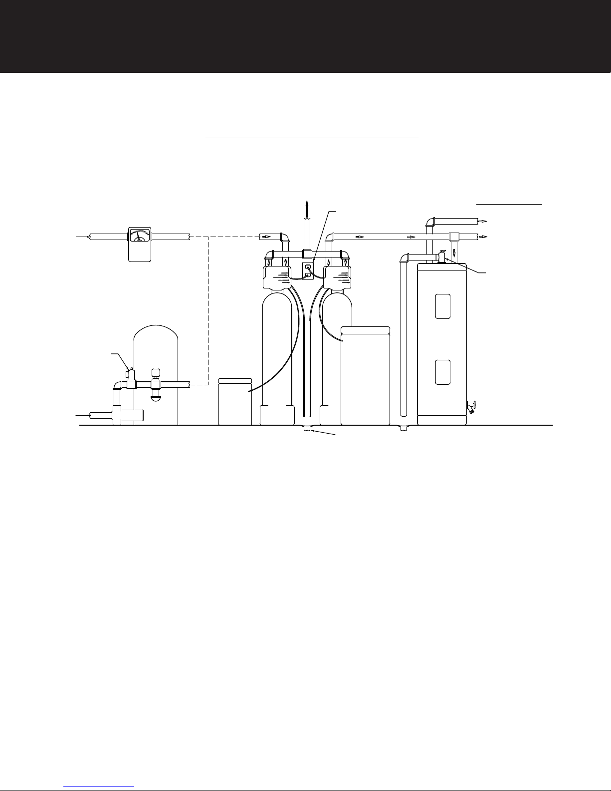
-Installation Requirements-
Feed Pot Tank
• A level floor position between the well pump and pressure tank. (See Typical Installation Diagram.)
• DO NOT install in an area of direct sunlight or where freezing temperatures may occur!
Filter Tank
• A level floor position ahead of piping into water heater.
• Unit must be installed at least 10’ ahead of the inlet to a water heater to prevent damage due to back-up of hot
water.
• DO NOT install the unit in an area of direct sunlight or where freezing temperatures may occur! (See Typical Installation
Diagram.)
4
Page 6

SIGNATURE 2 SERIES
Installation
• Locate the unit near an unswitched, 120 volt / 60 Hz grounded electrical outlet.
• Check for distance and proper drain installation (e.g. floor drain, washing machine standpipe).
• Determine type and size of piping required for softener connection (e.g. copper, galvanized, PVC plastic).
Note: Where the drain line is elevated above the control valve or exceeds 20 feet in length to reach the drain, use 3/4”
I.D. drain line tubing of 1/2” I.D. Drain line tubing is not included.
Caution: If sweat soldering copper pipe, (remember to always use lead free solder and flux) cover yoke and bypass valve
with wet rags to prevent heat damage to connections and control valve! If using PVC or plastic pipe, primers
and solvent cements specifically recommended for use with potable water are required.
Note: All plumbing lines not requiring soft water should be connected upstream of the filter. (See Typical Installation
Diagrams.)
To allow for filter servicing, swimming pool filling or lawn sprinkling, a manual bypass valve has been installed at the
factory. The bypass allows raw water to be manually routed around the filter.
-Filter Location / Other Requirements-
-Installation Procedure-
-Water Supply Connection and Bypass Valve-
1. Position filter at desired location for installation. If a water softener is to be installed, the filter should be positioned first
and then the softener. (See Installation Diagrams.)
2. The filter material is shipped separately from the mineral tank. The tank must be loaded with material after tank has
been placed at the desired location.
a. Remove the control valve by unscrewing from the tank.
b. Remove and inspect distributor tube and bottom basket.
c. Replace distributor tube and use a cork or tape to place over top of distributor tube to prevent mineral from
entering tube while filling.
d. Place mineral funnel in hole on top of tank.
e. Pour several gallons of water in the tank.
Caution: Not following this procedure can cause damage to distributor tube or basket when loading material!
f. First pour in the filter material.
Note: The required quantity of gravel is in the tank already.
g. After filling the tank with material, use a garden hose or several buckets to fill the tank with water.
Note: This will permit the filtering material to become soaked while preparing the installation and will prevent the control
valve from being plugged with floating material on initial backwash.
h. Remove funnel and clean filter material from tank threads.
i. Remove cork or tape from distributor tube.
j. Replace control valve on mineral tank.
Caution: Be extremely careful to position distributor tube into control valve distributor tube pilot hole.
3. Turn off main water supply and open nearest faucet to relieve pressure.
4. Cut main line and install elbows and extensions. Inlet and outlet connections on the control valve are 3/4” FNPT.
Note: An optional 1” FNPT bypass is available.
Caution: Raised arrows located on the sides of control valve body and bypass valve indicate proper direction of water
flow. Install inlet and outlet piping in direction of arrows.
5. Rotate handle on bypass valve to the bypass position (position of handle is across inlet/outlet piping).
6. Turn the main supply line on to restore water service to the home.
7. Open nearest faucet to evacuate air and repressurize plumbing lines.
8. Check for leaks!
5
Page 7

SIGNATURE 2 SERIES
Installation
-Drain Line Connection-
1. Pull out clip and remove drain line assembly located on the left side of control valve. Remove drain line hose barb and
wrap threads with Teflon tape. Reinstall drain line hose barb. Caution: Hand tighten only!! Replace drain line assembly
and reinstall clip.
2. Install 1/2” I.D. line tubing (not included) from hose barb to an open drain. A 4” gap between the end of the drain line
and the open drain is required to prevent waste water backflow. Keep the drain line as short as possible. An overhead
drain line can be used if necessary but should discharge below the control valve. A syphon trap (taped loop)
at the outlet of the drain line is advisable to keep the drain line full and assure correct flow during regeneration. Elbows
or other fittings must be kept at a bare minimum.
Note: Where the drain line is elevated above the control valve or exceeds 20’ in length, 3/4” I.D. drain line tubing should
be used.
-Potassium Permanganate Feed Rate-
The amount of potassium permanganate fed during regeneration is automatically controlled by the float assembly located
inside the feed tank. This is an adjustable float, which must be set at a minimum of 4 1/4”, but not higher than 5 1/2”. This
distance is measured between the bottom of chemical feed valve and the bottom of the float with the valve closed (float
UP position). The float settings for each model are as follows:
Model # Float Setting Media Amount
IF-10-S2 4 1/4” 1.0 cu. ft.
IF-15S2 4 1/2” 1.5 cu. ft.
IF-20-S2
IF-25-S2 5 1/2” 2.0 cu. ft.
1. To measure and set the float, remove the chemical well cap and float assembly.
2. Remove rubber band from float valve.
3. Measure distance from bottom of chemical feed valve to the bottom of float with the float in the UP position. To move
float, slide rubber grommets up and down float shaft. Make certain both upper and lower grommets are
tightly against float body. Replace float assembly and chemical well cap.
WARNING: After adjustment, ensure that the float maintains proper up and down travel, otherwise, overfilling of the feed
tank could occur!
-Chemical Feed Line and Overflow Connections-
1. Position Potassium Permanganate Tank (KMNO4) on a smooth, level surface near the filter media tank. If necessary,
the KMNO4 tank can be placed at a higher level than the resin tank, but never at a lower level.
2. Install one end of 3/8” O.D. by 1/4” I.D. chemical line tubing (included with unit) to compression fitting located on right
side of control valve, behind backplate.
3. Remove KMNO4 tank cover.
4. Insert opposite end of chemical line through outer hole in KMNO4 tank.
5. Connect chemical line to compression fitting on float valve located on top of chemical well.
6. Install 1/2” I.D. drain line tubing (not included) to the overflow fitting on KMNO4 tank located just below the chemical
line.
7. Run the opposite end of KMNO4 tank drain line to a suitable drain.
Note: The KMNO4 tank drain is gravity flow and must discharge below the overflow fitting.
Caution: Do not tee to the main drain line from control valve.
NOTICE: The KMNO4 overflow is provided as a back-up in the event the float shut-off should fail, allowing the KMNO4
tank to overfill. This drain connection would then carry the excess chemical to the drain and prevent flooding of the floor,
which could be hazardous to health or damage furniture or carpets. Therefore, no liability will or can be assumed by the
manufacturer of the filter should this occur.
6
Page 8
SIGNATURE 2 SERIES
Installation
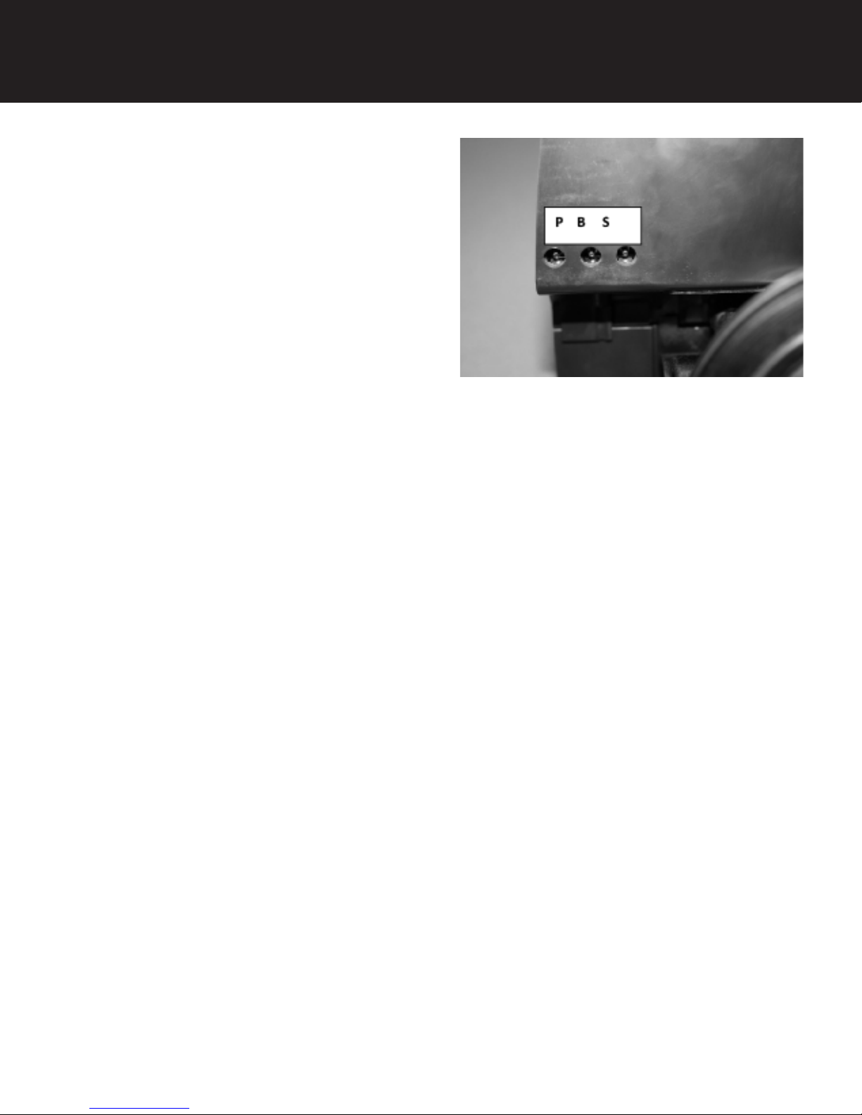
Electronic Connections
P - Power Supply
B - Powered in Backwash Cycle Only
S - Powered in Entire Regeneration Cycle
- Electrical Connection -
1. Connect the power supply to the control valve and plug into a 115 volt / 60 Hz receptacle.
Note: Do not plug into an outlet controlled by a wall switch or pull chain that could inadvertently be
turned off.
-Pressurizing The System -
2. Slowly rotate handle of the bypass valve to the SERVICE position.
3. Open the nearest faucet to evacuate air from plumbing lines.
4. Check for leaks! If water is observed leaking from bypass, o-rings on valve body may not be seated properly.
5. After air is evacuated from plumbing lines, turn off faucet.
- Initial Control Valve Operation -
1. Advance control valve to BACKWASH (cycle 1) position and allow water to run to drain for 3 to 4
minutes.
Warning: Close handle on bypass prior to selecting the backwash position. After backwash position
has been established, slightly open valve on bypass to evacuate air from the media tank.
Fully open bypass valve when all air is depleted. This procedure will prevent media form
being uplifted into control valve.
2. Advance control valve to RAPID RINSE (cycle 3) position and allow water to run to drain for 3 to 4
minutes.
3. Advance control valve to SERVICE (cycle 0) position.
7
Page 9
SIGNATURE 2 SERIES
Control Start-Up Procedures
- Final Checkout -
1. Be certain that the bypass valve is in Service position and main valve is completely on.
2. Check electrical supply to be certain the cord is connected to an uninterrupted 115 volt outlet.
3. Be certain the warranty card is filled out and mailed in.
4. Leave this manual with the homeowner.
Important Notice - The plumbing system, piping, pressure tank, hot water tanks, softeners, etc. that have been exposed
to iron bearing water may need to be cleaned of the precipitated iron that has been collected in them or iron bleed thru
may be a problem. We suggest all tanks be drained and flushed thoroughly.
- Programming The Control Valve -
1. Set time of day.
2. Set a.m. or p.m.
3. Set number of days between backwash. (This generally will be every 4 to 6 days.)
1. Set regeneration time if other than 12:00 a.m. is desired.
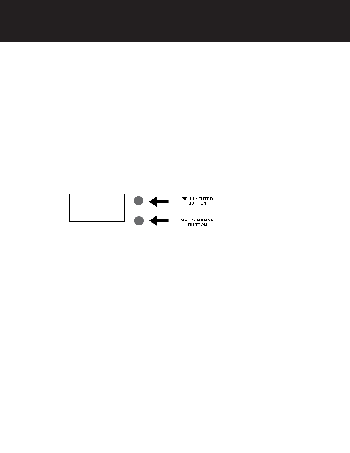
Main Menu
12:00
1. To enter Main Menu, press the Menu/Enter button.
(Time of Day will flash)
2. To set the Time of Day, press the Set/Change button.
(First digit will flash) Example (12:00)
- To change digit value, press the Set/Change button.
- To accept the digit value, press the Menu/Enter button.
- Next digit will flash to begin setting.
- Once the last digit display is accepted, all digits will flash.
3. To set A.M. or P.M., press the Menu/Enter button.
- To change digit value, press the Set/Change button. Example ( A )
- To accept the digit value, press the Menu/Enter button.
- Once A.M. or P.M. is accepted, the next menu item will flash.
4. a. To set the Number of Days between Backwash Cycles (A), press the Set/Change button.
- Repeat instructions from step (2). Example ( A - 06 )
Notes: 1) Maximum value is 29.
2) If value set to 0, Automatic Backwash will never occur.
3) Default setting is 6 days for filters.
5. To Exit Main Menu, press the Menu/Enter button.
Note: If no buttons are pressed for 60 seconds, the Main Menu will be exited automatically.
8
Page 10

SIGNATURE 2 SERIES
Control Start-Up Procedures
Normal Operation
1. Home Display
a. Alternates between the display of Time of Day and Number of Days until the Next
Backwash. (Metered Softeners will alternate between time of days and gallons
remaining until next regeneration)
- Days Remaining until the Next Backwash will count down from the entered
value until it reaches 1 day remaining.
- A Backwash Cycle will then be initiated at the next designated regeneration
time.
2. Battery Back-Up (Uses a standard 9-volt alkaline battery.)
Features of Battery Back-Up:
• During power failures, the battery will maintain the time of day as long as the
battery has power. The display is turned off to conserve battery power during
this time. To confirm that the battery is working, press either button and the
display will turn on for five (5) seconds.
• If power failure occurs while system is regenerating, the Isobar 2
will motor to a shut off position to prevent constant flow to drain. Depending
upon system pressure and other factors, it is possible to observe a reduced flow to
drain during this step. After power is restored, the Isobar 2 will return
and finish the cycle where it left off prior to the power interruption.
• When used without battery back-up, during a power failure, the unit stops at its
current point in the regeneration position and then restarts at that point when the
power is restored. The time will be offset by the increment of time the unit was
without power, so it is necessary to reset the time of day on the unit. No other
system will be affected.
9
Page 11
SIGNATURE 2 SERIES
Control Start-Up Procedures
Starting Extra Regeneration Cycle
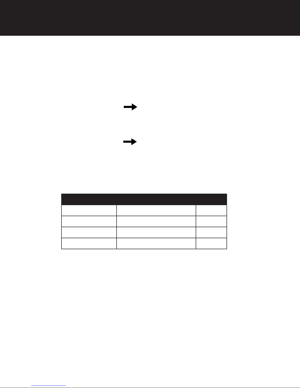
1. To Start Delayed Extra Cycle Example ( 1 )
- If Days Remaining Until Next Backwash does not read ‘1’, press and hold the
Set/Change button for 3 seconds until the display reads ‘1’.
- Backwash cycle will initiate at the next designated backwash time.
2. To start Immediate Extra Cycle First complete above step.
- With Days Remaining Until Next Regeneration at ‘1’.
- Press and hold the Set/Change button.
- After 3 seconds, the backwash cycle will begin.
3. To Fast Cycle thru regeneration First complete above 2 steps.
Note: Press and hold the Set/Change button for 3 seconds to advance to the next cycle step.
Fast Cycle is not necessary unless desired to manually step through each cycle step.
(Repeat until valve returns to the home display)
Filters Default (Min)
Step 1 Backwash 10
Step 2 Brine Draw 60
Step 3 Rapid Rinse 10
Step 4 Refill 4
10
Page 12
SIGNATURE 2 SERIES
Utilizing Bluetooth Control
To take advantage of the Bluetooth interface this feature must be set up on a Bluetooth enabled device.
Note: At the time of this release Bluetooth control only works on Android devices with a compatible version
of Bluetooth.
1. Download the Legacy View app from the Google Play Store or www.ChandlerSystemsInc.com
2. Pair the smart phone or tablet to the control valve
- Open the settings menu on your smart phone or tablet and click on Bluetooth.
- Look for the softener or filter valve under the list of available Bluetooth devices.
- Select the device and pair (Default password is: 1234)
3. Once the devices are paired open the Legacy View app
- Click the Legacy View logo in the top left corner to refresh the list of connected paired control valves
and select which valve you would like to view.
FCC ID: SWPLV-019
Name of Grantee: CHANDLER SYSTEMS, INC.
Equipment Class: Part 15 Low Power Communication Device
Notes: Legacy View Valve
This device complies with part 15 of the FCC Rules. Operation is subject to the following conditions: (1) this device may not cause harmful interference, and (2) this device must accept any interference
received, including interference that may cause undesired operation. Changes or modifications not expressly approved by the party responsible for compliance could void the user’s authority to operate
the equipment. NOTE: This equipment has been tested and found to comply with the limits for a Class B digital device, pursuant to Part 15 of the FCC Rules. These limits are designed to provide
reasonable protection against harmful interference in a residential installation. This equipment generates, uses and can radiate radio frequency energy and, if not installed and used in accordance with
the instructions, may cause harmful interference to radio communications. However, there is no guarantee that interference will not occur in a particular installation. If this equipment does cause harmful interference to radio or television reception, which can be determined by turning the equipment off and on, the user is encouraged to try to correct the interference by one or more of the following
measures:
- Reorient or relocate the receiving antenna.
- Increase the separation between the equipment and receiver.
- Connect the equipment into an outlet on a circuit different from that to which the receiver is connected.
- Consult the dealer or an experienced radio/TV technician for help.
11
Page 13

SIGNATURE 2 SERIES
Master Programming Mode
Master Programming Mode
To enter Master Programming Mode, press and hold both buttons for 5 seconds.
Note: All Master Programming functions have been preset at the factory. Unless a change is desired,
it is NOT necessary to enter Master Programming Mode.
1. Regeneration Time ( r ) Example ( r 12A )
- The time of day at which backwash may take place is designated by the letter “r”.
- Default regeneration time settings is 12a
- The first display digit indicates A.M. or P.M. To change the value, press the Set/Change button.
- Press Menu/Enter button to accept the value and move to the next digit.
- The second and third display digits indicate the hour at which the backwash will occur.
- Change the digits with the Set/Change button and accept with the Menu/Enter button.
- After the entire display flashes, press the Menu/Enter button to move to the next menu item.
2. Regeneration Cycle Step Times (Steps 1, 2, 3, 4)
Example ( 3 - 10)
- The next 4 displays set the duration of time in minutes for each backwash cycle step.
- The step number which is currently modifiable is indicated on the far left of the display
screen.
- The number of minutes allotted for the selected backwash step is displayed on the far
right.
- Change the digit values using the Set/Change and Menu/Enter buttons as described
above.
3. Bluetooth Enabled BE - 1 (ON)
BE - 0 (OFF)
4. Bluetooth Password BBPP is displayed for one second, then password is displayed.
5. To Exit the Master Programming Mode, press the Menu/Enter button until time of day returns.
Note: If no buttons are pressed for 60 seconds, the Master Programming Mode will be exited
automatically.
12
Page 14
SIGNATURE 2 SERIES
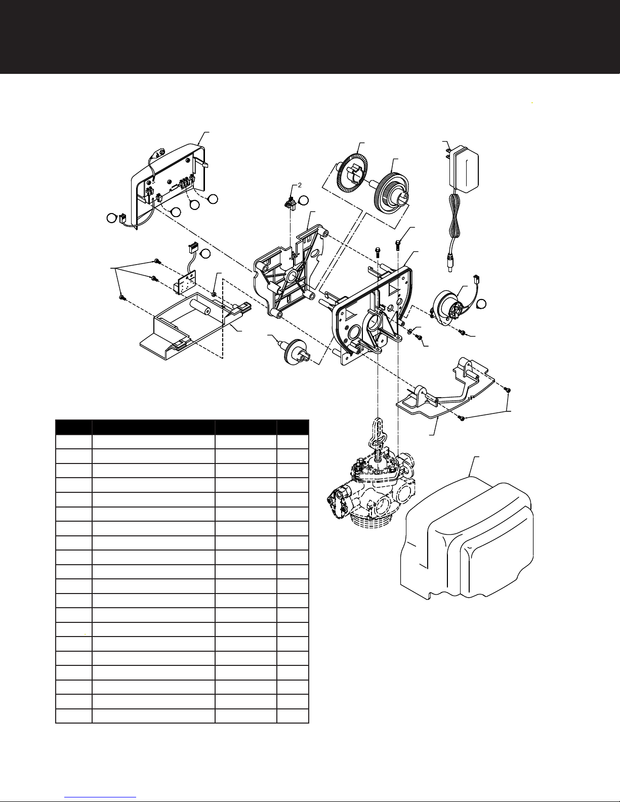
Control Valve Powerhead Assembly
1
M
P
E
13
LETTERS IN DIAGRAM REPRESENT WIRING CONNECTIONS
* "F" Port is for softener flow meter connection (flow meter not shown)
F
P
16
8
19
Ref Description Part Number Qty
0 Timered Power Head Assy. 21001X100 1
0 Metered Power Head Assy. 21003X100 1
1 Softener Circuit Boad Assy. 21001X102 1
2 Encoder 20001X124 1
3 Front Plate 20001X004 1
4 Encoder Wheel 20001X007 1
5 Main Gear 20001X120 1
6 Power Supply 20001X125 1
7 Back Plate 20001X005 1
8 Lower Front Base For Cover 20111X002 1
9 Motor 21001X113 1
10 Lower Back Base for Cover 20111X003 1
11 Valve Cover 20111X000 1
12 Piston Screw 20001X007 1
13 Screw SC10 3
14 Screw SC9 3
15 Piston Washer 20001X002 1
16 Washer Circuit Board 20111X014 1
17 Screw Motor SC2 1
21 Valve Hex Screw 20001X001 2
4
5
E
3
6
18
7
9
M
15
17
12
14
10
11
13
Page 15
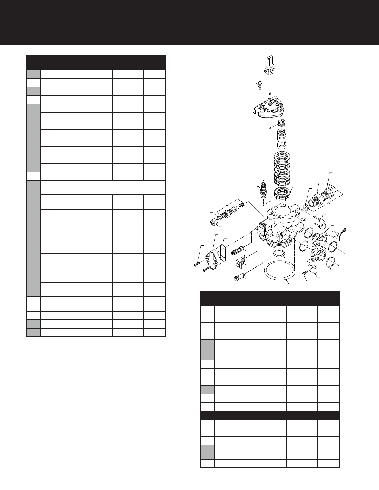
SIGNATURE 2 SERIES
Valve Body Drive Assy.
Ref
#
1 Piston Assembly 20001X231 1
2 10-24 x 13/16 Screw 20001X226 3
3 Seal & Spacer Kit 20561X253 1
4 End Spacer N/S 1
5 Flow Control Button 1.5 GPM 20251X266 1
6 Plastic Flow Control Housing 20251X100 1
6a Flow Control Assembly – Specify GPM Incl. (1) each
7 Drain Line Fitting 90º Elbow
8 Drain Retainer 20001X214 1
9 Brine Assembly 20561X225 1
10 BLFC Assembly .5 GPM 20001X228 1
Description Part # Qty.
Flow Control Button 2.0 GPM 20251X267 1
Flow Control Button 2.4 GPM 20251X268 1
Flow Control Button 3.0 GPM 20251X269 1
Flow Control Button 3.5 GPM 20251X270 1
Flow Control Button 4.0 GPM 20251X271 1
Flow Control Button 5.0 GPM 20251X272 1
Flow Control Button 7.0 GPM 20251X274 1
#20 thru #23
Flow Control Assy. 1.5 GPMPVC
Flow Control Assy. 2.0 GPMPVC
Flow Control Assy. 2.4 GPMPVC
Flow Control Assy. 3.0 GPMPVC
Flow Control Assy. 3.5 GPMPVC
Flow Control Assy. 5.0 GPMPVC
Flow Control Assy. 7.0 GPMPVC
1/2” NPT X 1/2” Tubing
20251X256 1
20251X257 1
20251X258
20251X259 1
20251X260 1
20251X262 1
20251X264 1
20251X255 1
2
1
3
9
4
6
5
10
11
12
14
15
13
16
20
17
18
19
Ref
#
11 Brine Line Ferrule 20251X305 1
12 Brine Line Compression Nut N/S 1
13 10-24 X 1 Hex Screw 20001X226 1
14 Injector Cap 20001X223 1
14a Injectory Kit-Specify Size- Inc.
15 Injector Seal 20001X224 1
16 Injector Assy. Specify Size 20001X219 1
17 Injector Screen 20001X222 1
18 Injector Plug & O-Ring Assy. 20001X217 1
19 O-Ring 2000X215 1
20 O-Ring 20561X204 1
Items #21 thru #24 used ONLY with clock regeneration
21 Mounting Clip 20561X201 2
22 8-18 X 5/8” Screw 20561X217 2
23 Adapter Coupling N/S 2
23a Adapter Coupling & O Ring
24 O-Ring 20561X216 4
Description Part # Qty.
20001X220 1
(1) ea #14, #15, #16, #17 &
(2) #13
20561X215 1
Assy. Incl. (1) #40 & (2) # 41
22
21
7
6A
8
23
24
14
Page 16
SIGNATURE 2 SERIES
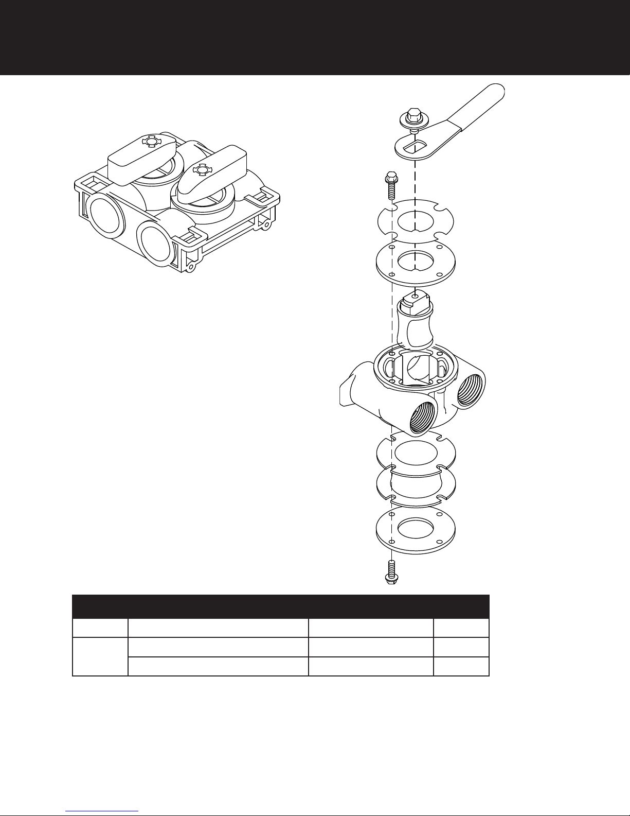
Bypass Assembly
(1)
15
(2)
Ref # Description Part # Qty
1
2
Plastic Bypass Valve Assembly 20561X292
Bypass Valve 3/4” Stainless Steel 20561X270
Bypass Valve 1” Stainless Steel 20561X283
1
1
1
Page 17

SIGNATURE 2 SERIES
Service Instructions / Instructional Videos
Service Instructions / Instructional Videos
Available at www.csiwater.com
Available at www.csiwater.com
A. General Preliminary Instructions
PERFORM BEFORE ALL SERVICING OPERATIONS
1. Turn off water supply to conditioner.
-If the conditioner installation has a “three valve” bypass system, first open the valve in
the bypass line, then close the valves at the conditioner inlet and outlet.
-If the conditioner has an integral bypass valve, put it in the bypass position.
-If there is only a shut off valve near the conditioner inlet, close it.
2. Remove cover and relieve water pressure in the conditioner by stepping the control into
the backwash
position momentarily. Return the control to the service position.
3. Unplug electrical cord from outlet.
B. To Replace Injectors & Screen
1. Follow steps A1 - A3 (above)
2. Remove injector cap screws and remove cap.
3. Remove injector assembly. Apply silicone lubricant to new injector assembly O rings and
install. Be sure to push injector assembly tightly so O rings are seated. Install a new
screen.
4. Apply silicone lubricant to new gasket and install on injector cap.
5. Follow D7 - D14.
C. To Replace Powerhead
1. Remove the control valve cover and disconnect the power supply.
2. Disconnect the meter cable from circuit board and feed back through control (if existing
meter is being re-used)
3. Remove screw and washer at drive yoke. Remove powerhead mounting screws. The
entire powerhead assembly will now lift off easily.
4. Put new powerhead on top of the valve. Be sure the drive pin on main gear engages slot
in drive yoke (wide side of drive yoke upright must face to the left away from the motor).
5. Replace powerhead mounting screws. Replace screw and washer at drive yoke.
6. Reconnect meter signal, optical sensor, power supply, and circuit board signal wires.
7. Reinstall cover.
16
Page 18

SIGNATURE 2 SERIES
D. To Replace Brine Valve
1. Follow steps A1 - A3
2. Remove the control valve cover. Disconnect the meter cable from the meter
assembly.
3. Remove screw and washer at piston drive yoke. Remove powerhead mounting
screws. The entire powerhead assembly will now lift off easily.
4. Remove piston retaining plate screws and pull upward on end of piston yoke until
assembly is out of valve.
5. Pull brine valve from valve body.
6. Apply silicone lubricant to O ring on new brine valve assembly and press into brine
valve hole, shoulder on bushing should be flush with injector body.
7. Reinstall piston and powerhead assembly.
8. Reconnect brine tube and drain line.
9. Return bypass or inlet valving to normal service position. Water pressure should now
be applied to the conditioner, and any bypass line shut off.
10. Check for leaks at all seal areas. Check drain seal with the control in the backwash
position.
11. Plug electrical cord into outlet.
12. Set time of day and cycle control valve manually to assure proper function. Make sure
control valve is returned to the service position.
13. Make sure there is enough salt in the brine tank.
14. Start regeneration cycle manually if water is hard.
15. Replace control valve cover.
Service Instructions / Instructional Videos
Available at www.csiwater.com
E. To Replace Piston Assembly
1. Follow steps A1 - A3
2. Remove control valve back cover. Disconnect the meter signal wire from the meter.
3. Remove screw and washer at piston drive yoke. Remove powerhead mounting screws.
The entire powerhead assembly will now lift off easily.
4. Remove piston retaining plate screws.
5. Pull upward on end of piston yoke until assembly is out of valve.
6. Inspect the inside of the valve to make sure that all spacers and seals are in place, and
that there is no foreign matter that would interfere with the valve operation.
7. Take new piston assembly and push piston into valve by means of the end
plug. Twist drive yoke carefully in a clockwise direction to properly align it with drive
gear. Reinstall piston retaining plate screws.
8. Place powerhead on top of valve. Be sure drive pin on main gear engages slot in drive
yoke (wide side of drive yoke upright must face to the left away from the motor).
9. Replace powerhead mounting screws. Replace screw and washer at drive yoke.
10.Follow steps D9 - D14.
17
Page 19

SIGNATURE 2 SERIES
Service Instructions / Instructional Videos
Available at www.csiwater.com
F. To Replace Seals and Spacers
1. Follow steps A1 - A3.
2. Remove the control valve cover. Disconnect the meter signal wire from the meter.
3. Remove screw and washer at piston drive yoke. Remove powerhead mounting screws.
The entire powerhead assembly will now lift off easily. Remove piston retaining plate
screws.
4. Pull upward on end of piston rod yoke until assembly is out of valve. Remove seals and
spacers. (Note: Special end spacer must be reused)
5. Lubricate new seals with silicone lubricant included in the seal and spacer kit. Make
sure the special end spacer is properly seated in the valve body. Install new seals and
spacers individually, pressing around the outer edge of each seal to make sure it is
seated.
(When all seals and spacers are seated properly, you will have a 1/4” of space between
the top seal the the top of the valve body)
6. Follow Steps E7 - E10.
G. To Replace Meter
1. Follow steps A1 - A3
2. Remove two screws and clips at bypass valve or yoke. Pull softener tank away from
plumbing connections.
3. Remove meter cable from meter.
4. Remove two screws and clips at meter and pull the meter out of the control valve.
5. Apply silicone lubricant to O rings on new meter.
6. Attach meter to control valve. Note: meter portion of module must be assembled on
valve outlet. Install two screws and clips.
7. Plug meter cable into new meter.
8. Attach two clips and screws at bypass valve or yoke. Be sure clip legs are firmly
engaged with lugs.
9. Follow steps D9 - D14.
18
Page 20
SIGNATURE 2 SERIES
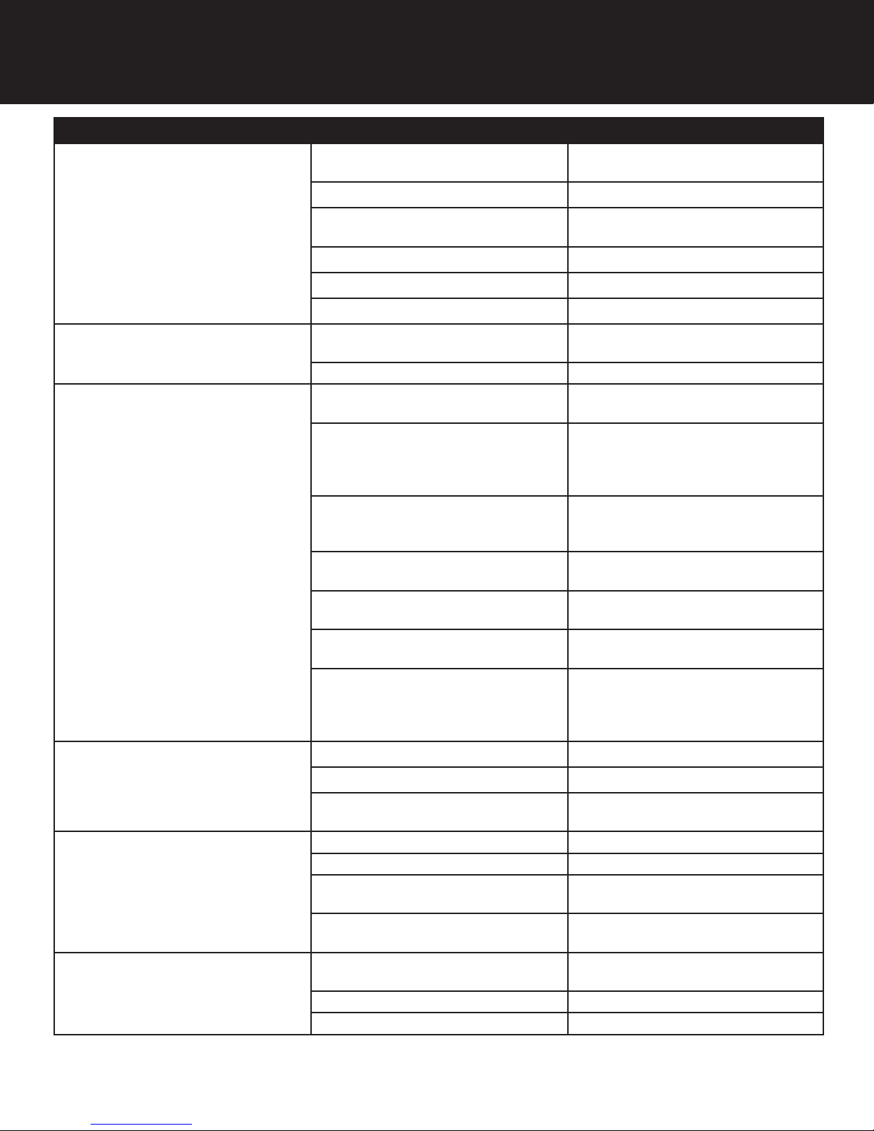
Troubleshooting Guide
SYMPTOM PROBABLE CAUSE CORRECTION
1.Softener Fails to
Regenerate
Automatically
Power supply plugged into
intermittentent or dead power source
Disconnected meter cable Reconnect cable
Improper control valve
programming
Defective power supply Replace power supply
Meter is dirty or defective Clean or replace meter assembly
Defective Drive motor Replace motor
Connect to constant power source
Reset program settings
2. Regeneration at
Wrong Time
3. Loss of Capacity
Time of day improperly set, due to
power failure
Regeneration time set improperly Reset regeneration time programming
Increased raw water hardness Increase hardness setting or decrease
Brine concentration and or / quantity Keep brine tank full of salt at all times.
Resin fouling Call dealer. Find out how to confirm
Poor distribution, channeling (uneven
bed surface)
Internal valve leak Call dealer. Replace spacers, seals
Resin age Call dealer. Check for resin oxidation
Resin loss Call dealer. Check for correct bed
Check items listed in #1, #2, and #3
Reset time of day programming and
install 9-volt battery.
days between regeneration
Clean it yearly. Salt may be bridged.
If using a salt grid plate, ensure refill
water is over it.
it. Clean the resin and prevent future
fouling.
Call dealer. Check backwash flow.
Regenerate more frequently
and / or piston
caused by chlorine. Mushy resin.
depth. Broken distributor tube. Air or
gas in bed: well gas eliminator. Loose
brine line.
4. Poor Water Quality
5. High Salt Usage
6. Loss of Water Pressure
20
Bypass valve open Close bypass valve.
Channeling Check for too slow or high service
flow. Check for media fouling.
High salt setting Lower brine tank refill time
Excessive water in brine tank See symptom #7
Constant flow through the unit Indicates plumbing leak (e.g. toilet
tank)
Regenerating too frequently Lower hardness setting or increase
days between regeneration.
Scaling / fouling of inlet pipe Clean or replace pipline. Pretreat to
prevent.
Fouled resin Clean resin. Pretreat to prevent.
Improper backwash setting Backwash more frequently
Page 21
SIGNATURE 2 SERIES
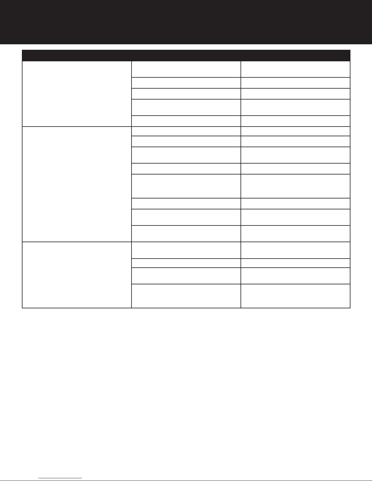
Troubleshooting Guide
SYMPTOM PROBABLE CAUSE CORRECTION
Plugged drain line or drain line control Check flow to drain. Clean drainline
flow control button
7. Excessive Water in
Brine Tank and / or
Salty Water to Service
Dirty or damaged brine valve Clean or replace brine valve.
Plugged injector or screen Clean or replace injector screen.
Low inlet pressure Increase pressure to allow injector to
perform properly. (20 psig minimum)
Excessive brine refill cycle time Lower brine refill time.
Check items listed in #1
Improper control valve programming Check and reset programming
Plugged / restrict drain line Clean drain line and / or flow control
button
Injector and / or screen is plugged Clean or replace injector and screen
8. Softener Fails to Use
Salt
No water in brine tank Check for restriction in BLFC. Ensure
safety float is not stuck. Check brine
tank for leaks.
Water pressure is too low Line pressure must be at least 20 psi.
Brine line injects air during brine draw Check brine line connectionsfor air
leaks
Internal control leak Call dealer. Check piston, seals and
spacers for scratches and dents.
9. Continuous Flow to
Drain
Foreign material in control piston and
seals
Internal control leak Same as above.
Valve jammed in backwash, brine or
rapid rinse position
Motor stopped or jammed Check for jammed piston. Replace
Call dealer. Clean valve and replace
piston and seals.
Same as above.
piston and seals. Replace motor if
motor is unresponsive.
Error Codes
There are five (5) error codes which could indicate a possible problem with the control valve:
Error 2 - Valve is searching for homing slot.
Allow valve to run until homing slot is found or new error code appears.
Error 3 - No encoder slots are being seen.
Check encoder connection. If encoder is connected. Check valve body for debris
and replace seals. Inspect piston and replace if worn.
Error 4 - Unable to find homing slot.
Check encoder wheel for debris.
Error 5 - Motor overload.
Check valve body for debris. Replace seals. Inspect piston and replace if worn.
Check motor operation and replace motor if unresponsive.
Error 6 - No power to motor. Check motor connections, replace motor if unresponsive.
21
Page 22
SIGNATURE 2 SERIES
Page 23

SIGNATURE 2 SERIES
Notes:
Page 24

SIGNATURE 2 SERIES
710 Orange Street, Ashland, OH 44805
PH 419.289.1500 FAX 419.289.1515
www.watersoftinc.com
 Loading...