

Page 1
Single Color (Black)
Communications Specialties’ Fiberlink® Card Cage User’s Manual
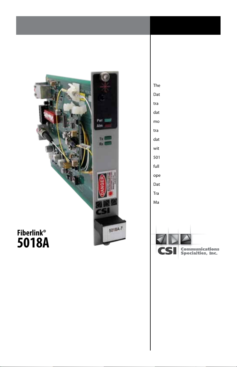
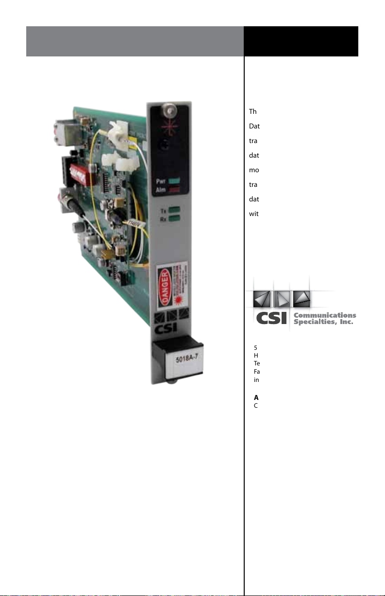
The Fiberlink® 5018A Universal
Data Transceiver digitally
transmits RS-232/422/485
data over multimode or single
mode ber at 850 or 1310 nm. It
transmits and receives all standard
data-related signals in accordance
with EIA specications. The
5018A is suitable for simplex,
full duplex and drop-and-repeat
operation, making it ideal for
Data Acquisition, Intelligent
Transportation, Industrial and
Manufacturing applications.
Fiberlink®
5018A
Universal Data Transceiver
for the Fiberlink® 6000A Card Cage
World Headquarters
55 Cabot Court
Hauppauge, New York 11788 USA
Tel: (631) 273-0404
Fax: (631) 273-1638
[email protected]
Asia
Communications Specialties Pte Ltd
100 Beach Road
#22-09 Shaw Tower
Singapore 189702
Tel: +65 6391 8790
Fax: +65 6396 0138
[email protected]
commspecial.com
Page 2

Fiberlink® 5018A
Contents
Contents
Welcome . . . . . . . . . . . . . . . . . . . . . . . . . . . . . . . . . . . . . . . . . . . . . . . . . . . . . . . . . . . . . . . . . . . . . . . . 3
Features. . . . . . . . . . . . . . . . . . . . . . . . . . . . . . . . . . . . . . . . . . . . . . . . . . . . . . . . . . . . . . . . . . . . . . . . . 3
Package Contents . . . . . . . . . . . . . . . . . . . . . . . . . . . . . . . . . . . . . . . . . . . . . . . . . . . . . . . . . . . . . . . 3
Quick Installation . . . . . . . . . . . . . . . . . . . . . . . . . . . . . . . . . . . . . . . . . . . . . . . . . . . . . . . . . . . . . . . . 4
Technical Specications
Model Part Number Specications . . . . . . . . . . . . . . . . . . . . . . . . . . . . . . . . . . . . . . . . . . . . 5
Operation Theory . . . . . . . . . . . . . . . . . . . . . . . . . . . . . . . . . . . . . . . . . . . . . . . . . . . . . . . . . . . . . . . 6
Installation Instructions . . . . . . . . . . . . . . . . . . . . . . . . . . . . . . . . . . . . . . . . . . . . . . . . . . . . . . . . . . 7
Signal and Power Connections . . . . . . . . . . . . . . . . . . . . . . . . . . . . . . . . . . . . . . . . . . . . . . . . . . . 8
DIP Switch Settings . . . . . . . . . . . . . . . . . . . . . . . . . . . . . . . . . . . . . . . . . . . . . . . . . . . . . . . . . . . . . 10
Modes of Operation . . . . . . . . . . . . . . . . . . . . . . . . . . . . . . . . . . . . . . . . . . . . . . . . . . . . . . . . .10
T/R Time Settings (Baud Rate) . . . . . . . . . . . . . . . . . . . . . . . . . . . . . . . . . . . . . . . . . . . . . . .15
Alarm Switch Settings . . . . . . . . . . . . . . . . . . . . . . . . . . . . . . . . . . . . . . . . . . . . . . . . . . . . . . . . . . 16
Optical Fiber Types Supported . . . . . . . . . . . . . . . . . . . . . . . . . . . . . . . . . . . . . . . . . . . . . . . . . .16
Indicator LEDs . . . . . . . . . . . . . . . . . . . . . . . . . . . . . . . . . . . . . . . . . . . . . . . . . . . . . . . . . . . . . . . . . . 16
Conguring a Ring or Loop Data Bus . . . . . . . . . . . . . . . . . . . . . . . . . . . . . . . . . . . . . . . . . . . .17
Operating Pointers . . . . . . . . . . . . . . . . . . . . . . . . . . . . . . . . . . . . . . . . . . . . . . . . . . . . . . . . . . . . . 19
Troubleshooting . . . . . . . . . . . . . . . . . . . . . . . . . . . . . . . . . . . . . . . . . . . . . . . . . . . . . . . . . . . . . . . 19
Maintenance and Repairs . . . . . . . . . . . . . . . . . . . . . . . . . . . . . . . . . . . . . . . . . . . . . . . . . . . . . . . 20
Warranty . . . . . . . . . . . . . . . . . . . . . . . . . . . . . . . . . . . . . . . . . . . . . . . . . . . . . . . . . . . . . . . . . . . . . . .21
Accessories and Related Products . . . . . . . . . . . . . . . . . . . . . . . . . . . . . . . . . . . . . . . . . . . . . . . 22
Page 2 Fiberlink® 5018A User’s Manual
Page 3

Fiberlink® 5018A
Welcome | Features | Package Contents
Welcome
Thank you for purchasing Communications Specialties, Inc.’s Fiberlink® 5018A. The 5018A
transmits and receives all standard data-related signals in accordance with EIA
specications. The 5018A is suitable for simplex, full duplex and drop-and-repeat operation,
making it ideal for Data Acquisition, Intelligent Transportation, Industrial and
Manufacturing applications.
Features
• Transmits and receives all standard data-related signals in accordance with EIA
specications
• May be easily user-congured for the desired protocol, including mixed protocols
• Transmitter and receiver may be congured dierently
• Adjustment free; all digital processing and transmission
• Wide operating data rate, with low-speed mode (DC up to 2.1 mbps; 200 Kbps for
RS-232) and high-speed mode (10 Kbps - 10 mbps)
• Extended ambient operating range
• Data-derived or RTS transmit/receive switching (RS-485)
• Indicator LEDS monitor signal and power
• Card version lls one slot in 6000A card cage
• RoHS Compliant
Package Contents
• One Fiberlink® 5018A
• This User’s Manual
Page 3Fiberlink® 5018A User’s Manual
Page 4
Fiberlink® 5018A
Quick Installation
Quick Installation Guide
The following is a quick installation guide for the 5018A model. It is intended for users
familiar with the installation of ber optic transmission systems to get “up and running”
in minimal time. Since these units are capable of being congured for operation in many
dierent modes, we strongly suggested that you consult the appropriate sections of this
manual.
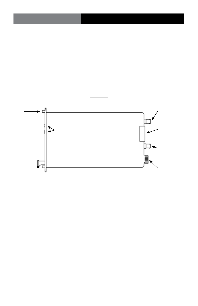
Card Cage
Locking Screws
LED Indicators
The 5018A is designed to operate in any available position in a model 6000A cardcage.
When installed, all operating power is provided by the card-cage.
The 5018A are ESD protected to + 10 kV on all inputs and outputs.
5018A
RX Optical
Connector
Signal
Connector
Tx Optical
Connector
Card Cage
Power
Connector
Page 4 Fiberlink® 5018A User’s Manual
Page 5

Fiberlink® 5018A
Technical Specications
General Information
The Universal Data Transceiver is fully compatible with EIA standards for RS-232, RS-422 and
RS-485 at data rates from 0 (DC) to 2.1 mbps (200 kbps for RS-232) in the low speed mode
or from 10 kbps to 10 mbps in the high speed mode. It may be used for simplex or full
duplex asynchronous transmissions in both point-to-point systems and drop-and-repeat
data networks. It may also be used as a protocol converter. Although there are no operating
controls, the user must congure the unit for the protocol, speed and mode of operation
desired.
The Universal Data Transceiver comes in two versions, the 5012 stand-alone model and the
5018A card cage model. The two models are fully compatible with each other.
Technical Specications
Model Part Number Specication
System Protocols* EIA RS-232, RS-422, RS-485, 2-wire or 4-wire
System Data Rate* Low speed: RS-232, DC-200 kbps,
RS-422/485, DC to 2.1 mbps
High speed: RS-422/485, 10 kbps to 10 mbps
Modes of Operation* Simplex, duplex, drop-and-repeat,
Asynchronous, RTS or
Data Derived T/R control
Operating Wavelength 850 nm or 1310 nm
Optical Connectors ST (MM) or FCPC (SM)
Operating Temperature -35 to +75 degrees C
Wavelength Loss Budget (dB) Distance (km) Loss Budget (dB) Distance (km)
Low Speed Low Speed High Speed High Speed
850 MM 0-12 0-4 0-6 0-2
1310 MM 0-14 0-14 0-8 0-8
1310 SM 0-15 0-35 0-8 0-20
Distance specications are only approximate and are not guaranteed. Loss budget must not be exceeded.
* Note that as provided from the factory, the universal data transceiver is set to the RS-232 point-to-point
(200 kbps) and low speed modes of operation.
In the low speed mode the unit will operate with all duty cycles including DC (logic 0 or logic 1
continuously). In the high speed mode of operation, the system will operate properly with all duty cycles
from 50-50% to 70-30%.
Page 5Fiberlink® 5018A User’s Manual
Page 6
Fiberlink® 5018A
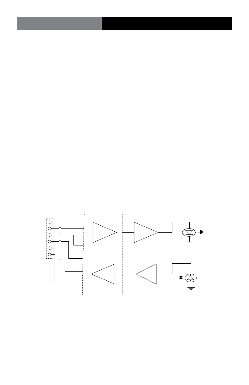
1
2
3
6
LED Driver
Current/Voltage
Converter
Transmit
LED
Receive
Photodiode
Protocol Converter
4
5
Signal
Terminal Block
Operation Theory
Theory of Operation
The transmitting section of the universal data transceiver converts an incoming RS-232,
RS-422 or RS-485 signals into pulses of light at the transmitting LED located in the “Transmit
(or Tx)” optical connector on the unit. These pulses of light equate to ON for a positive input
level and OFF for a negative or zero input level.
The receiving section of the universal data transceiver produces a user selectable RS-232,
RS-422 or RS-485 compatible output from the received light at the photodiode located in
the “Receive (or Rx)” optical connector on the unit. Due to the fact that all internal logic
signals are converted to either light-on or light-o, any protocol may be used in conjunction with any other protocol, thereby allowing the transceiver to be used as a data
converter as well as a general data transceiver. In addition, provision is incorporated to
allow drop and repeat operation with any protocol.
During normal operation, the RTS line (terminal block position 6) is not used. In external
RTS operation (for RS-485), terminal block position 6 is used as an enable input to toggle
the unit between transmit and receive. In this mode a positive input switches the unit to
the transmit mode while a zero input switches the unit to the receive mode. As an alternative, the unit may be automatically switched from transmit to receive by means of an
internal data-driven timer (Data-Derived T/R switching).
UNIVERSAL DATA TRANSCEIVER BLOCK DIAGRAM
Page 6 Fiberlink® 5018A User’s Manual
Page 7

Fiberlink® 5018A
Installation
Installation instructions
There are no operating controls on the universal data transceiver. Simply set the mode of
operation with the internal DIP switches and then connect the signal, power supply and
ber optic cables between the two units.
1. Connect the data processing equipment to be used to the 6 position terminal block
on the 5018A . Refer to the signal and power connections section on page 10 for specics.
Be certain that the various connections are made properly. Also be sure to only use
the positions called out for any particular protocol.
2. Set the internal DIP switches for the protocol, speed and mode of operation
according to the instructions beginning on page 10. Note: As provided from the
factory, the unit is set for RS-232, point-to-point.
3. Plug the unit into any free position in a model 6000A card-cage.
4. Connect the 5018A units together with two conductor ber optic cable. Be certain
that the “Transmit” connector of one unit is connected to the “Receive” connector of
the other unit.
5. The system should now be operational.
The transmitting element in the Fiberlink® 5018A transmitter
unit contains a solid state Laser Diode located in the optical
connector. This device emits invisible infrared electromagnetic
radiation which can be harmful to human eyes. The radiation
from this optical connector, if viewed at close range with no
ber optic cable connected to the optical connector, may be
sucient intensity to cause instantaneous damage to the
retina of the eye. Direct viewing of this radiation should be
avoided at all times!
Page 7Fiberlink® 5018A User’s Manual
Page 8
Fiberlink® 5018A
Signal and Power Connections
Signal and Power Connections
The 5018A is designed to operate in any available position in a model 6000A cardcage.
When installed, all operating power is provided by the card-cage.
The 5018A is ESD protected to + 10 kV on all inputs and outputs.
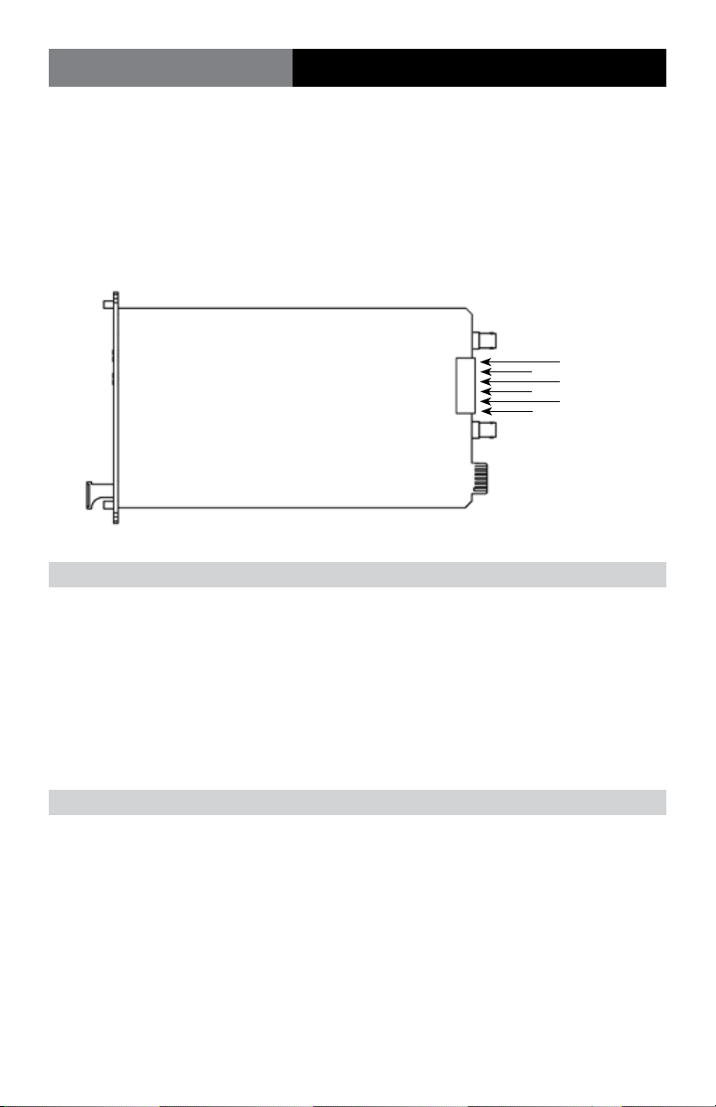
Data Connector Pin Out:
Pin 6
Pin 5
Pin 4
Pin 3
Pin 2
Pin 1
RS-232 Signal Connections:
Description EIA Designation Terminal Positions
Chassis Ground/Common (AA) 1
Transmit Data (BA) (input) 2
Receive Data (BB) (output) 4
Signal Common (AB) 1
All other terminal block positions should not be connected for this format.
RS-422 Signal Connections:
Chassis Ground 1
Transmit Data (+) (input) 2
Transmit Data (-) (input) 3
Receive Data (+) (output) 4
Receive Data (-) (output) 5
All other terminal block positions should not be connected for this format.
Page 8 Fiberlink® 5018A User’s Manual
Page 9

Fiberlink® 5018A
Signal and Power Connections
RS-485 2-Wire Signal Connections:
Chassis Ground 1
Transmit/Receive Data (+) (input/output) 2
Transmit/Receive Data (-) (input/output) 3
RTS Enable (when used) (input) 6
All other terminal block positions should not be connected for this format.
RS-485 4-Wire Signal Connections:
Chassis Ground 1
Transmit Data (+) (input) 2
Transmit Data (-) (input) 3
Receive Data (+) (output) 4
Receive Data (-) (output) 5
RTS Enable (when used) (input) 6
All other terminal block positions should not be connected for this format.
When the RTS mode of operation is used, the input to terminal 6 must be “high” for the unit to transmit data
and “low” to receive data.
Page 9Fiberlink® 5018A User’s Manual
Page 10
Fiberlink® 5018A
DIP Switch Settings
Modes of Operation:
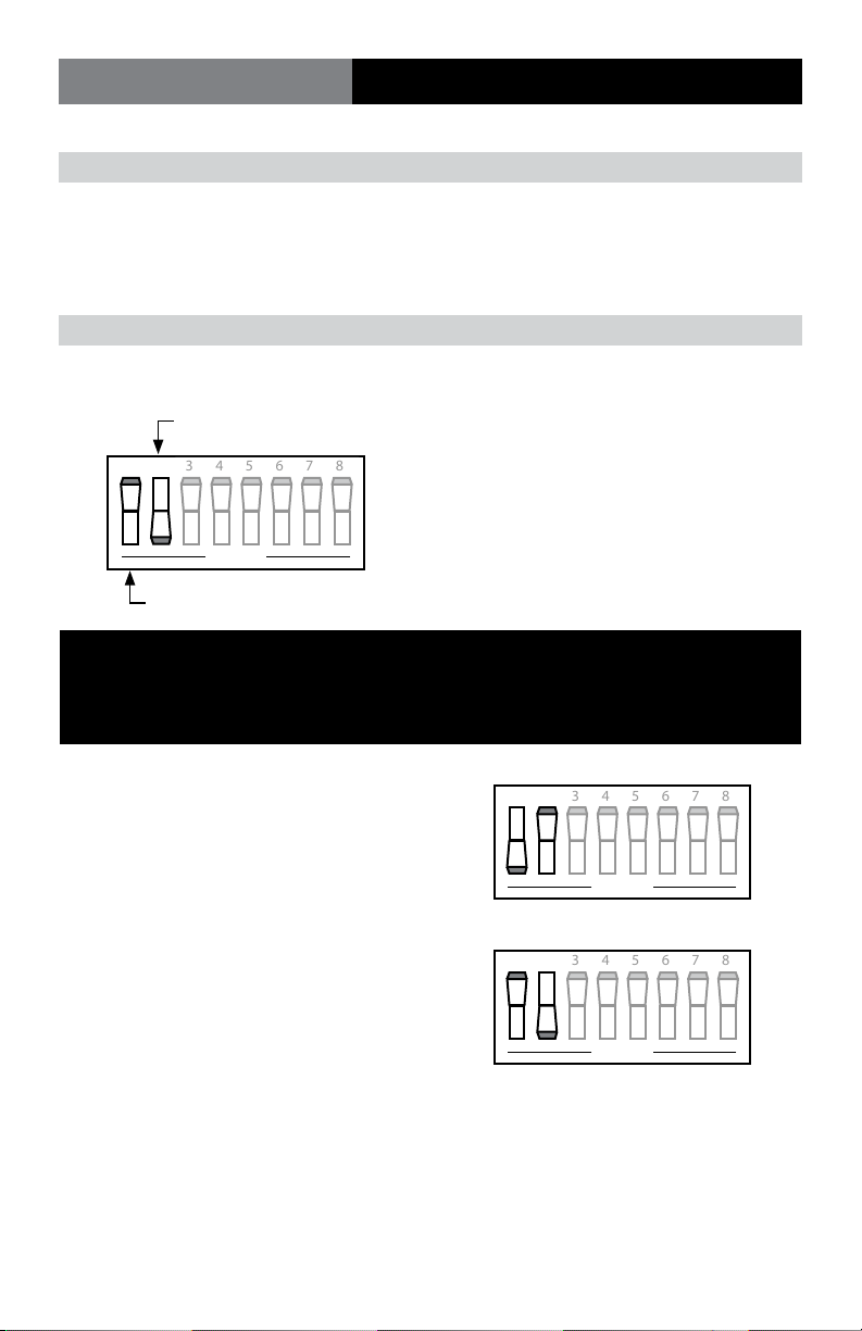
On the 5018A card-cage model, there are three DIP switch banks located on the
printed circuit card. Switch Bank S1 sets the Mode of Operation, Switch Bank S2
sets the Baud Rate (RS-485 Data Format) and Switch Bank S3 sets the Alarm.
Setting the MODE DIP switch
Switch setting example
Switch ON (CLOSED)
1 2 3 4 5 6 7 8
O P E N
Switch O (OPEN)
Low Speed or High Speed Operation:
For all protocols, positions 1 and 2 of the MODE DIP switch (S1) MUST be set
as either Low Speed or High Speed Operation as follows:
Low speed mode (DC to 2.1 mbps):
1 2 3 4 5 6 7 8
Position 1 = ON, Position 2 = OFF
O P E N
High speed mode (10 kbps to 10 mbps):
1 2 3 4 5 6 7 8
Position 1 = OFF, Position 2 = ON
O P E N
For RS-232, the data rate is limited to 200 kbps. For RS-422/485, the data rate is as above.
The universal data transceiver will not operate properly if positions 1 and 2 are both set to either ON or OFF.
Page 10 Fiberlink® 5018A User’s Manual
Page 11
Fiberlink® 5018A
DIP Switch Settings
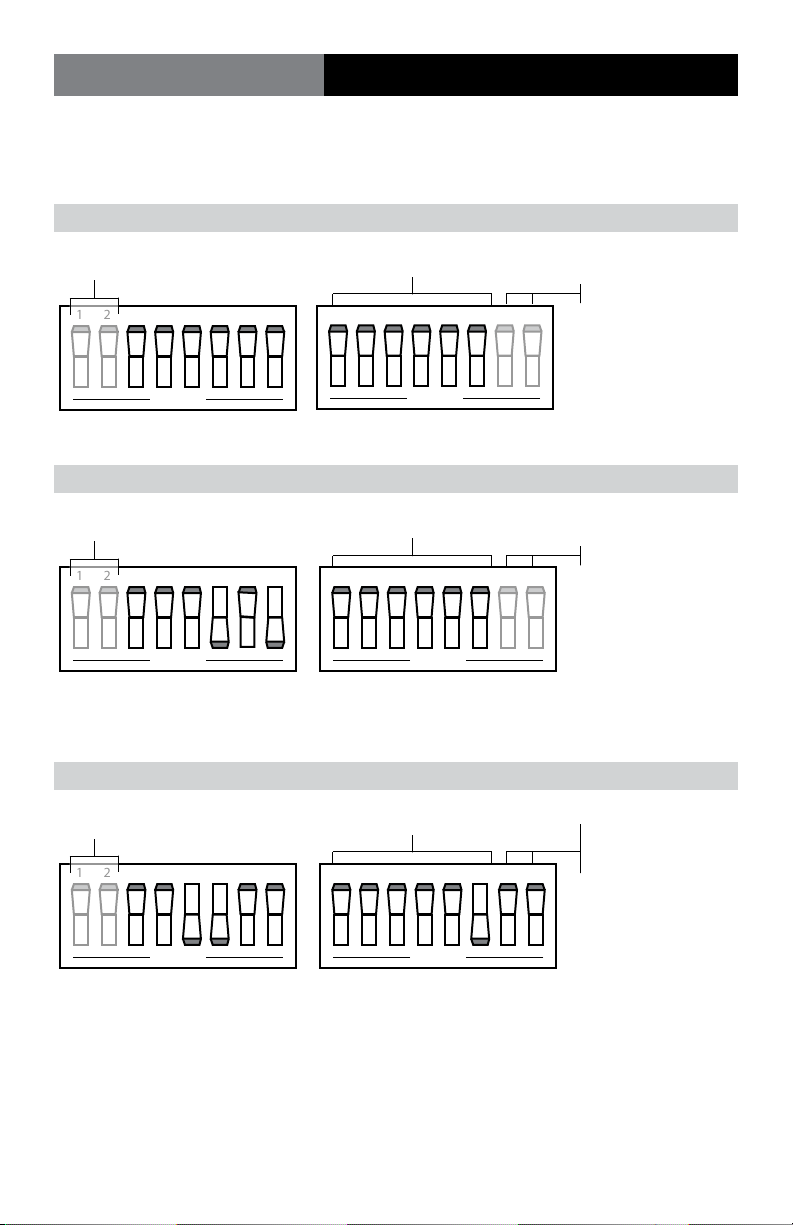
Use the following protocol-specic settings to nish conguring the MODE DIP switch
on your universal data transceiver.
RS-232 Point-to-Point (Factory-Default Setting)
See Page 10
1 2 3 4 5 6 7 8
O P E N
1 through 6 O
Not Applicable
1 2 3 4 5 6 7 8
O P E N
Mode T/R
RS-232 Drop-and-Repeat
See Page 10
1 2 3 4 5 6 7 8
O P E N
Mode T/R
When using this mode of operation, any RS-232 driver not transmitting data must be in the low or - voltage
state as per EIA RS-232D.
1 through 6 O
Not Applicable
1 2 3 4 5 6 7 8
O P E N
RS-422 Point-to-Point
See Page 10
1 2 3 4 5 6 7 8
Switch 6 ON
1 2 3 4 5 6 7 8
120 Ohm Termination
Switch 7 ON: data input
Switch 8 ON: data output
O P E N
O P E N
Mode T/R
Page 11Fiberlink® 5018A User’s Manual
Page 12
Fiberlink® 5018A
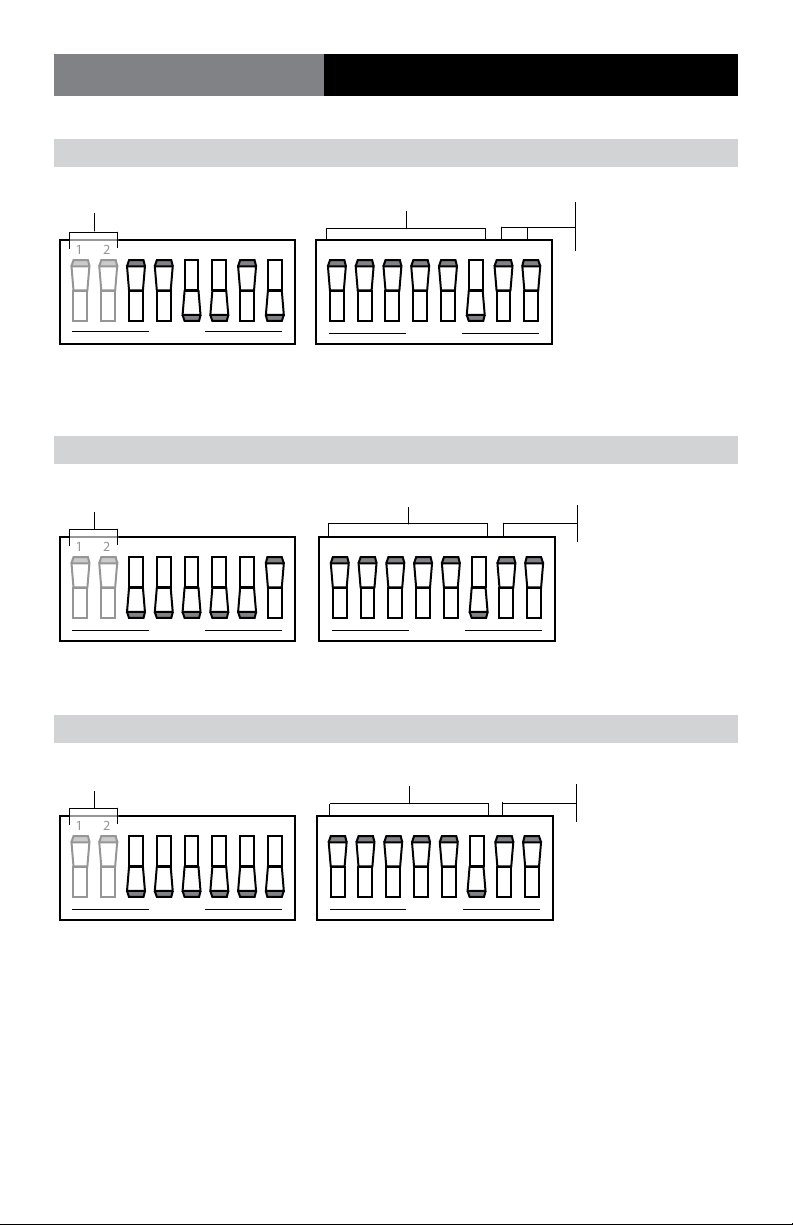
RS-422 Drop-and-Repeat
DIP Switch Settings
See Page 10
1 2 3 4 5 6 7 8
O P E N
Switch 6 ON
1 2 3 4 5 6 7 8
O P E N
120 Ohm Termination
Switch 7 ON: data input
Switch 8 ON: data output
Mode T/R
When using this mode, any RS-422 driver not transmitting data must be in the “low” state (terminal block
position 2, negative with respect to position 3).
RS-485 2-Wire Point-to-Point RTS Enable
See Page 10
1 2 3 4 5 6 7 8
O P E N
Mode T/R
In this mode, the input to terminal 6 must be “high” for the unit to transmit data and “low” to receive data.
Switch 6 ON
1 2 3 4 5 6 7 8
O P E N
120 Ohm Termination
Switch 7 ON: data line
RS-485 2-Wire Drop-and-Repeat RTS Enable
See Page 10
1 2 3 4 5 6 7 8
Switch 6 ON
1 2 3 4 5 6 7 8
120 Ohm Termination
Switch 7 ON: data line
O P E N
O P E N
Mode T/R
In this mode, the input to terminal 6 must be “high” for the unit to transmit data and “low” to receive data.
Page 12 Fiberlink® 5018A User’s Manual
Page 13
Fiberlink® 5018A
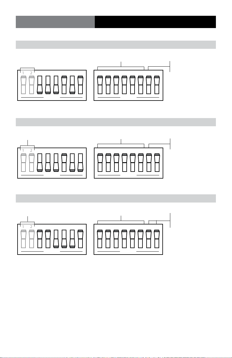
RS-485 2-Wire Point-to-Point Data Derived T/R
See Page 10
1 2 3 4 5 6 7 8
See Baud Rate
settings on page 15
1 2 3 4 5 6 7 8
DIP Switch Settings
120 Ohm Termination
Switch 7 ON: data line
O P E N
O P E N
Mode T/R
RS-485 2-Wire Drop-and-Repeat Data Derived T/R
See Baud Rate
See Page 10
1 2 3 4 5 6 7 8
O P E N
settings on page 15
1 2 3 4 5 6 7 8
O P E N
120 Ohm Termination
Switch 7 ON: data line
Mode T/R
RS-485 4-Wire Point-to-Point RTS Enable
See Page 10
1 2 3 4 5 6 7 8
O P E N
Mode T/R
In this mode, the input to terminal 6 must be “high” for the unit to transmit data and “low” to receive data.
All O
1 2 3 4 5 6 7 8
O P E N
120 Ohm Termination
Switch 7 ON: data input
Switch 8 ON: data output
Page 13Fiberlink® 5018A User’s Manual
Page 14
Fiberlink® 5018A
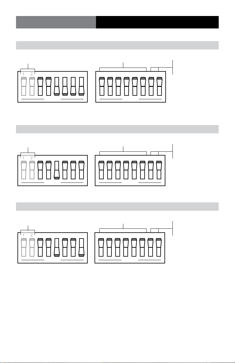
RS-485 4-Wire Drop-and-Repeat RTS Enable
DIP Switch Settings
See Page 10
1 2 3 4 5 6 7 8
O P E N
All O
1 2 3 4 5 6 7 8
O P E N
120 Ohm Termination
Switch 7 ON: data input
Switch 8 ON: data output
Mode T/R
In this mode, the input to terminal 6 must be “high” for the unit to transmit data and “low” to receive data.
RS-485 4-Wire Point-to-Point Data-Derived T/R
See Page 10
1 2 3 4 5 6 7 8
O P E N
Mode T/R
See Baud Rate
settings on page 15
1 2 3 4 5 6 7 8
O P E N
120 Ohm Termination
Switch 7 ON: data input
Switch 8 ON: data output
RS-485 4-wire Drop-and-Repeat Data-Derived T/R
See Baud Rate
See Page 10
1 2 3 4 5 6 7 8
settings on page 15
1 2 3 4 5 6 7 8
120 Ohm Termination
Switch 7 ON: data input
Switch 8 ON: data output
O P E N
O P E N
Mode T/R
Page 14 Fiberlink® 5018A User’s Manual
Page 15
Fiberlink® 5018A
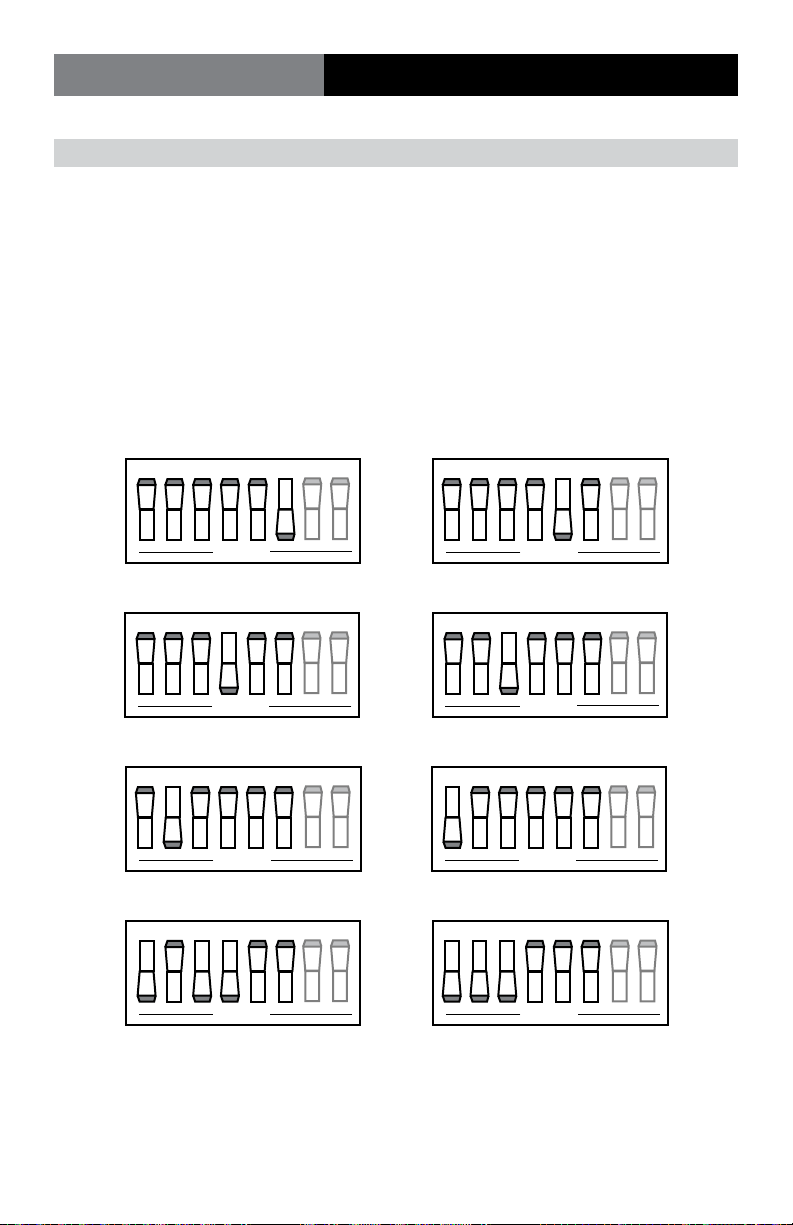
T/R Time (Baud Rate Settings) - Switch Bank S2
DIP Switch Settings
Baud Rate T/R Time 1 2 3 4 5 6 7 8
2400 4.73 ms O O O O O On NA NA
4800 2.20 ms O O O O On O NA NA
9600 1.10 ms O O O On O O NA NA
19.2K 620 us O O On O O O NA NA
38.4K 300 us O On O O O O NA NA
57.6K 180 us On O O O O O NA NA
76.8K 150 us On O On On O O NA NA
115.2K 110 us On On On O O O NA NA
2400
1 2 3 4 5 6 7 8
O P E N
9600
1 2 3 4 5 6 7 8
O P E N
38.4k
1 2 3 4 5 6 7 8
O P E N
76.8k
1 2 3 4 5 6 7 8
O P E N
4800
1 2 3 4 5 6 7 8
O P E N
19.2k
1 2 3 4 5 6 7 8
O P E N
57.6k
1 2 3 4 5 6 7 8
O P E N
115.2k
1 2 3 4 5 6 7 8
O P E N
After transmitting the last data bit, the above settings will determine how long the transceiver continues
to wait in the transmit mode for data before reverting to the receive state. The times specied are only
recommendations but will be correct for most applications. If desired, they can be varied to meet specic
data requirements.
Page 15Fiberlink® 5018A User’s Manual
Page 16

Fiberlink® 5018A
Alarm Switch Settings | Optical Fiber | Indicator LEDs
Setting the ALARM DIP (Switch Bank S3)
The third switch bank is used to set the user-congurable alarm feature that indicates the
loss of a data signal. When enabled, the continuous loss of data for more than 1 second will
be sensed and trigger this alarm. This feature will not operate properly in cases where logic
0 or no data bits last for more than 1 second.
To enable or disable the alarm function on the 5018 model, set the ALARM DIP switch as
follows
Transmit Data Signal Position 1: ON = enable OFF = disable
Receive Data Signal Position 2: ON = enable OFF = disable
Optical Fiber Types Supported
Versions of the universal data transceiver are available to drive most multimode (MM) and
single-mode (SM) optical bers. The specic models are identied by a sux at the end of
the model numbers as follows:
Fiber Size Connector 850nm 1300nm
50µ, 62.5µ MM ST -1 -3
8/10µ SM FCPC N/A -7
A 6300 adapter is available to allow the -1 and -3 versions of the 5018A model to be used
with multimode ber and SMA connectors. A 6310 adapter is available to allow
the -7 versions of these models to be used with single-mode ber and single-mode
ST connectors.
Indicator LEDs
The 5018A model has three green signal indicator LEDs that continuously monitor
operation. One, labeled “Power (or PWR)”, lights when operating power is present. The
other two, labeled “Transmit (or Tx)” and “Receive (or Rx)”, turn on whenever the
transmitted or received data is in the “high” state and o when it is in the “low” state.
As a result, they actually blink at the rate of the operating data. However, most data rates
are so fast that these LEDs will usually appear to be on continuously.
The 5018A also has a red LED labeled “ALRM” which lights when an alarm condition
is present.
Page 16 Fiberlink® 5018A User’s Manual
Page 17
Fiberlink® 5018A
Conguring a Ring or Loop Data Bus
Conguring a Ring or Loop-Type Data Bus
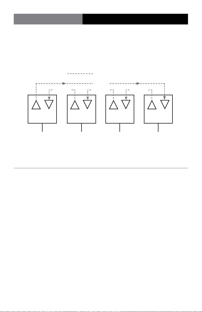
In addition to point-to-point transmissions, the universal data transceiver can be used to
implement a ring or loop-type data bus. This is accomplished by setting the internal DIP
switches as shown in the following diagram.
Fiber Optic Cable
Data Flow
Data FlowData FlowData Flow
Fiber Optic
Transceiver
To Host Computer
Set to point-to-point
mode of operation
Fiber Optic
Transceiver
Drop 3 Drop 2 Drop 1
Set to drop-and-repeat
mode of operation
Fiber Optic
Transceiver
Set to drop-and-repeat
mode of operation
Fiber Optic
Transceiver
Set to drop-and-repeat
mode of operation
Ring or Loop-Type Data Bus Conguration
When the Universal Data Transceiver is used in this mode, any location can receive or insert
data into the ring/loop but only one station at a time is permitted to insert data. All other
stations will receive the data but must maintain their individual input lines in the low state
(RS-232, terminal block position 2 negative with respect to position 1; RS-422, terminal
block position 2, negative with respect to position 3) to prevent loop lock-up. RS-485
operation does not have the above restriction due to the fact that it is in the tri-state mode
when not transmitting.
Note that the rst (or host) location is set to the point-to-point mode. All other locations are
set to the drop-and-repeat mode. This is to prevent loop lock-up or data “echos”.
Page 17Fiberlink® 5018A User’s Manual
Page 18

Fiberlink® 5018A
Considerations
Operating Considerations forFiber Optic Cable
The universal data transceiver may be supplied with ST or FCPC type optical connectors
and will operate with most common ber optic cables. However, it is important to use the
correct type of ber optic cable as required by your particular transceiver model. Some
models (ending in -1 and -3) are designed for use at 850 nm, while others (ending in -7)
function at 1300 nm.
When using any type of ber optic cable, be careful not to cause excessive strains, especially at the cable-to-connector junctions. Also, do not subject the cable to sharp bends or pull
it around sharp corners. Whenever possible, service loops or extra slack should be provided
in any installation. While excessive precautions are not necessary, ber optic cable should
be treated with moderate care as it does contain thin, fragile strands of glass.
Notes Regarding Fiber Optic Cable
Multimode ber optic cable contains an optical ber with a light carrying “core” that is only
.0025 inches (62.5µ) diameter. Single-mode ber optic cable has an even smaller “core”, only
00032 to .0004 inches (8-10µ). This is smaller than a human hair! Any minute particle of dirt
or dust can easily block this ber from accepting or radiating light. As a result, the key word
is cleanliness. Always use the dust caps provided with all optical connectors whenever they
are exposed to air. Also, it is a good idea to gently clean the tip of an optical connector with
alcohol whenever dust is suspected.
Mechanical butt splices or optical feedthroughs must be installed properly. Multimode
devices will not operate properly with single-mode devices even though they may look the
same. Using the wrong device can easily add more attenuation than specied, resulting in
impaired performance.
Page 18 Fiberlink® 5018A User’s Manual
Page 19

Fiberlink® 5018A
Operating Pointers | Troubleshooting
Operating Pointers
Remember to check attenuation of the ber optic cable. The system will only operate
properly if these specications fall within the range of the system’s loss budget.
Troubleshooting
Multimode ber optic cable contains an optical ber with a light carrying “core” that is
only .0025 inches (62.5 microns) in diameter. Single mode ber optic cable has an even
smaller “core,” only .00032 to .0004 inches (8-10 microns). This is smaller than a human hair!
Therefore, any minute particles of dirt or dust can easily block the ber from accepting or
radiating light. To prevent this from happening, always use the provided dust caps when
ever optical connectors are exposed to air. It is also a good idea to gently clean the tip of an
optical connector with a lint-free cloth moistened with alcohol whenever dust is suspected.
The status of the LEDs should provide the rst clue as to the origin of any operational
failure. If these are o, it usually means that the ber is broken or has too much attenuation.
Next, be certain that the input and output signal connections are correct.
An optical power meter, such as the Fiberlink® 6615, a visible light source, such as the
Fiberlink® 6610, and a Three Wavelength Light Source, such as the Fiberlink® 6620, can
greatly assist and expedite troubleshooting of ber optic transmission systems and are
recommended tools all installers should have available.
Finally, although multimode and single mode devices may look the same, they will not
operate properly together. Using the wrong device or ber can easily add more attenuation
than specied, resulting in poor overall performance. It should be noted that some of our
ber optic products support both single mode and multimode ber in the same unit.
If, after reviewing the above possibilities, the system is still not operating, please contact
the Customer Service Department for further assistance. If you suspect your problem is
caused by the optics or the ber optic cable, and you have an optical power meter, please
take the appropriate measurements prior to contacting support.
Page 19Fiberlink® 5018A User’s Manual
Page 20

Fiberlink® 5018A
Maintenance and Repairs | Certications
Maintenance and Repairs
The Fiberlink® 5018A Series has been manufactured using the latest semiconductor devices
and techniques that electronic technology has to oer. They have been designed for long,
reliable and trouble-free service and are not normally eld repairable.
Should diculty be encountered, Communications Specialties maintains a complete
service facility to render accurate, timely and reliable service of all products.
The only maintenance that can be provided by the user is to ascertain that optical
connectors are free of dust or dirt that could interfere with light transmission and that
electrical connections are secure and accurate. Please see the Troubleshooting section of
this manual for additional information.
An optical power meter, such as the Fiberlink® 6615, a visible light source, such as the
Fiberlink® 6610, and a Three Wavelength Light Source, such as the Fiberlink® 6620, can
greatly assist and expedite troubleshooting of ber optic transmission systems and are
recommended tools all installers should have available.
All other questions or comments should be directed to our Customer Service Department.
It should be noted that many “problems” can easily be solved by a simple telephone call.
If you suspect your problem is caused by the optics or the ber optic cable, and you have
an optical power meter, please take the appropriate measurements prior to contacting
support.
Certications
Page 20 Fiberlink® 5018A User’s Manual
Page 21

Fiberlink® 5018A
Warranty
Communications Specialties, Inc. (CSI) warrants that, for a period of three years after
purchase by the Buyer, this product will be free from defects in material and workmanship
under normal use and service. A Return Material Authorization (RMA) number must be
obtained from CSI before any equipment is returned by the Buyer. All materials must be
shipped to CSI at the expense and risk of the Buyer.
CSI’s obligation under this warranty will be limited, at its option, to either the repair or
replacement of defective units, including free materials and labor. In no event shall CSI be
responsible for any incidental or consequential damages or loss of prots or goodwill.
CSI shall not be obligated to replace or repair equipment that has been damaged by re,
war, acts of God, or similar causes, or equipment that has been serviced by unauthorized
personnel, altered, improperly installed, or abused.
RMA numbers and repairs can be obtained from:
Communications Specialties, Inc.
55 Cabot Court
Hauppauge, NY 11788 USA
Tel: (631) 273-0404
Fax: (631) 273-1638
or, in the Asia Pacific Region:
Communications Specialties Pte Ltd
100 Beach Road
#22-09 Shaw Tower
Singapore 189702
Tel: +65 6391 8790
Fax: +65 6396 0138
RMA numbers can also be obtained from our web site: commspecial.com
Please have your serial number available.
Page 21Fiberlink® 5018A User’s Manual
Page 22
Fiberlink® 5018A
Accessories and Related Products
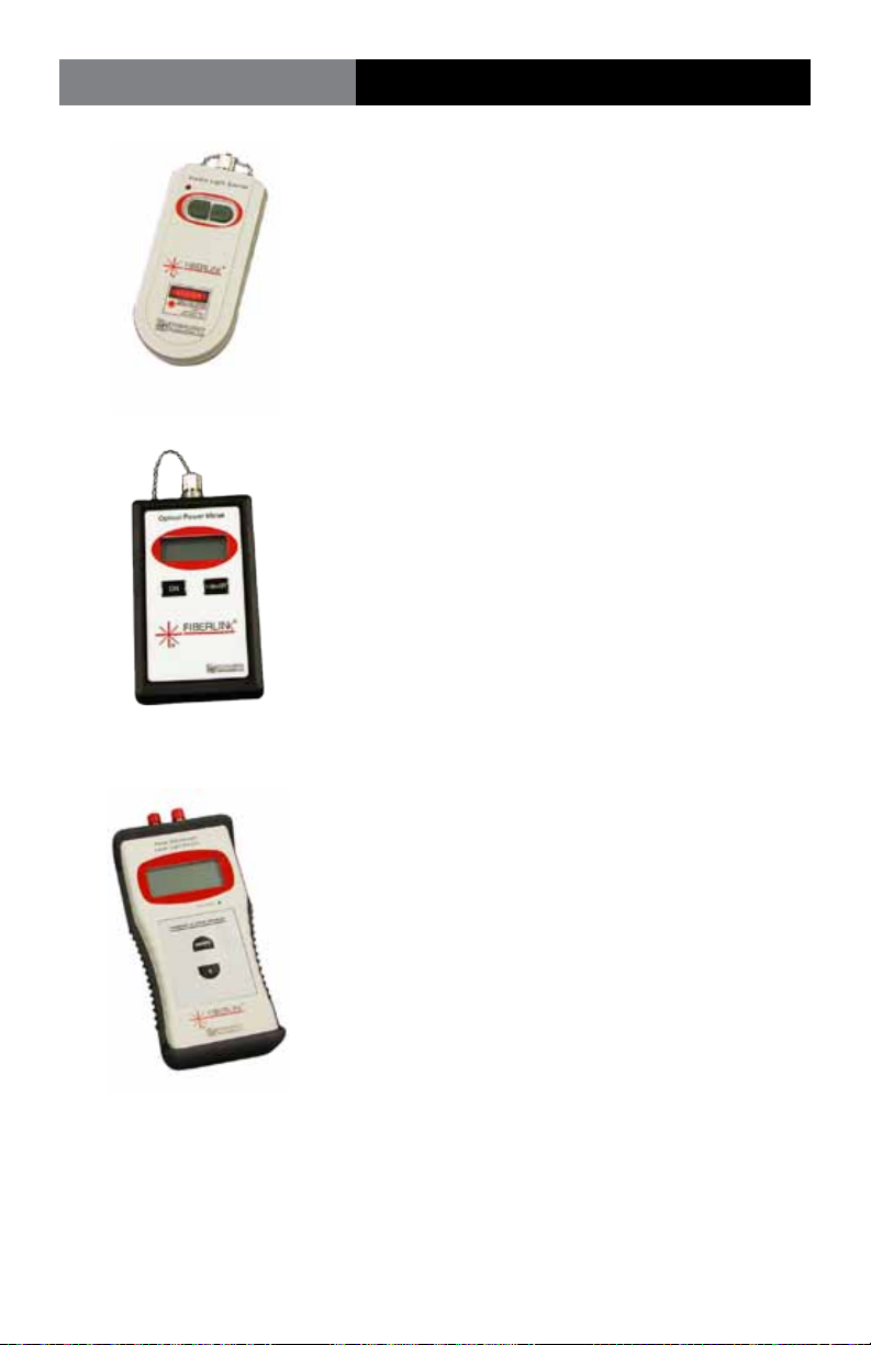
Fiberlink® 6610 Visible Light Source
The Fiberlink® Visible Light Source provides a
visible 650 nm laser output that can be used for
identifying ber breaks and individual bers within
ber bundles, allowing for convenient, on-site
testing of ber networks during construction
and maintenance procedures.
Fiberlink® 6615 Optical Power Meter
The Fiberlink® Optical Power Meter measures the
power of optical signals at 850, 980, 1310 and 1550
nm wavelengths, allowing for convenient, on-site
testing of ber networks during construction and
maintenance procedures. It can be used to measure
the power of an optical signal reaching the receiving
end of a ber optic cable, as generated either by a
transmitter unit or by a light source such as the 6620.
Fiberlink® 6620
Three Wavelength Light Source
The Fiberlink® Three Wavelength Light Source oers a
laser output at wavelengths of 1310 and 1550 nm and
VCSEL output at 850 nm, allowing for convenient,
on-site testing of ber networks during construction
and maintenance procedures.
Page 22 Fiberlink® 5018A User’s Manual
Page 23

Fiberlink® 5018A
Notes
Page 23Fiberlink® 5018A User’s Manual
Page 24
Single Color (Black)
Communications Specialties’ Fiberlink® 3350 User’s Manual
User’s Manual
The Fiberlink® 5018A Universal
Data Transceiver digitally
transmits RS-232/422/485
data over multimode or single
mode ber at 850 or 1310 nm. It
transmits and receives all standard
data-related signals in accordance
with EIA specications.
Fiberlink®
5018A
Universal Data Transceiver
for the Fiberlink® 6000A Card Cage
World Headquarters
55 Cabot Court
Hauppauge, New York 11788 USA
Tel: (631) 273-0404
Fax: (631) 273-1638
in[email protected]
Asia
Communications Specialties Pte Ltd
100 Beach Road
#22-09 Shaw Tower
Singapore 189702
Tel: +65 6391 8790
Fax: +65 6396 0138
[email protected]
commspecial.com
©2010 Communications Specialties, Inc.
All Rights Reserved.
Fiberlink and the starburst logo are
registered trademarks of
Communications Specialties, Inc.
CSI and the triangle designs are trademarks
of Communications Specialties, Inc.
P/N: 121459 Rev. F
 Loading...