

C-Sharp Bookshelf Speaker Kit User Manual
C-Sharp Bookshelf Speaker Kit
Thank you for purchasing the C-Sharp powered bookshelf speaker kit. This speaker kit was
precision cut using CNC machinery for the best possible fit and finish. With a little time and
patience, your finished product will provide years of enjoyment. Please follow the following
instructions for the best possible results.
Suggested tools and consumables:
Drill Rag or paper towels
5/64" drill bit Solder
Wood clamps (you can never have too many of these) Soldering iron
Sanding block and/or electric finishing sander Hot glue gun
Wood glue Polyurethane glue (Gorilla Glue)
0.11" female disconnect terminal Cyanoacrylate Adhesive (super glue)
0.205" female disconnect terminal
Package contents:
First, empty the contents of the package and review parts to ensure everything has been included
and is in good condition. If any parts are missing or damaged please contact our customer service
department at 1-800-338-0531.
Note: Crossover components may be substituted with parts of equal of higher quality depending
on stock.
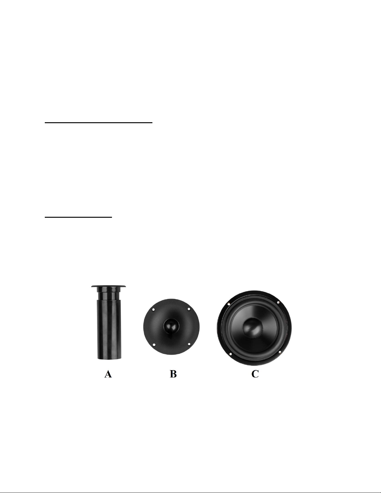
Components:
A) 1-3/8" ID adjustable port tube
B) Dayton Audio ND25FW-4 1" Soft Dome Neodymium Tweeter with Waveguide
C) Dayton Audio DSA135-8 5" Designer Series Aluminum Cone Woofer
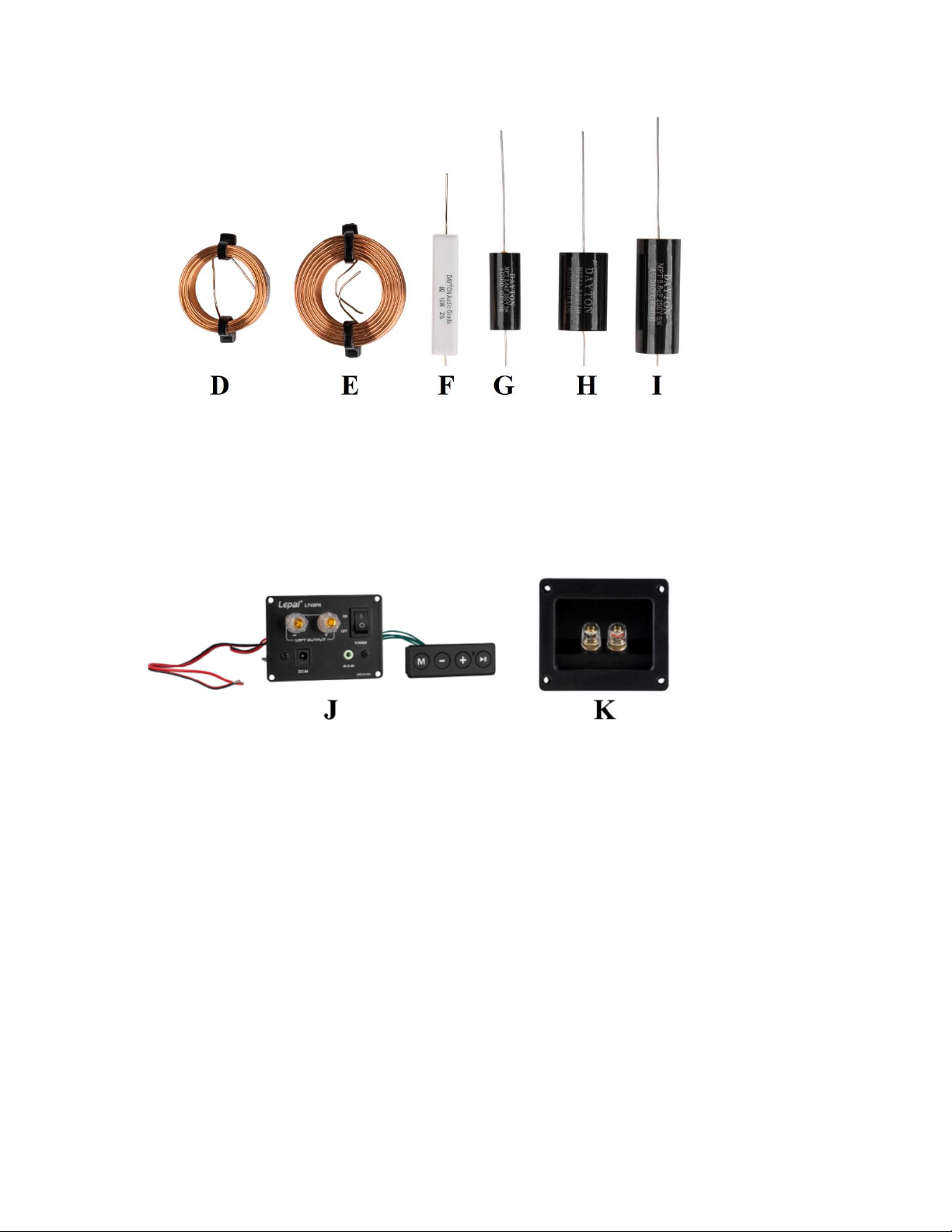
D) 2 x 0.25 mH air core inductor
E) 2 x 1.40 mH air core inductor
F) 2 x 6 ohm resistor
G) 4 x 2.0 µF capacitor
H) 2 x 5.1 µF capacitor
I) 2 x 6.8 µF capacitor
J) Gold Insulated 5-Way Binding Post Terminal Cup
K) Lepai LP40PA 40W Mini Plate Amplifier and Control Panel
Not Shown:
25-Pack #6 x 3/4" Pan Head Deep Thread Black Screws
10' Consolidated 16 AWG 2-conductor Power Speaker Wire 1 ft. (Red/Black)
Enclosures:
L) Front x 2
M) Mater Back (R etched onto the inside surface) x 1
N) Master Top (R etched onto the inside surface) x 1
O) Slave Back x 1
P) Slave Top x 1
Q) Bottom x 2
R) Sides x 4
Enclosure Assembly:
1) First, set the enclosure parts out on a flat level surface and ensure that all pieces are free of
dust and debris. Separate the master speaker (with amplifier, right) panels and the slave
speaker (no amplifier, left) panels into two separate piles. Note: the back and top panels of
the master have the letter "R" etched into the inside surface for easy identification. The
cutouts on the back panel of the master and slave enclosures are different, but very similar,
make sure these do not get mixed up.
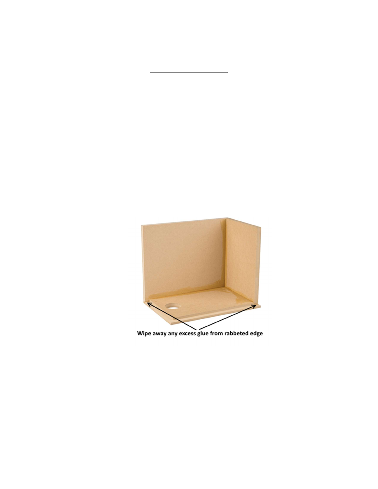
2) With the back panel of one enclosure lying flat, glue all mating surfaces of the bottom panel
and one side panel and secure them to the back panel with clamps so that even pressure is
applied to all glued surfaces. Using a damp rag or paper towel wipe away any glue squeezeout on the outside of the enclosure and inside the rabbeted edge (excess glue on the inside is
fine). Allow to dry according to the glue manufacturer's recommendations and remove
clamps.
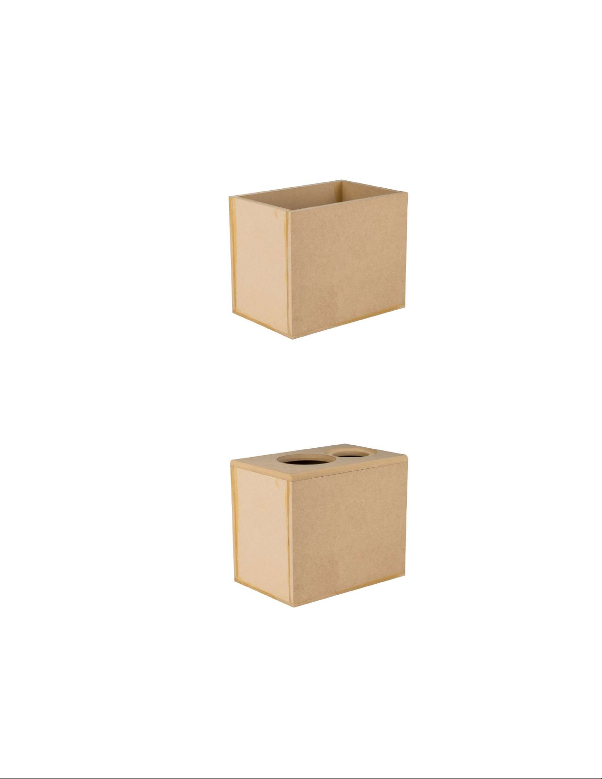
3) Next, glue all mating surfaces of the top panel and the other side panel and secure them in
place with clamps so that even pressure is applied to all glued surfaces. Using a damp rag or
paper towel wipe away any glue squeeze-out on the outside of the enclosure (excess glue on
the inside is fine). Allow to dry according to the glue manufacturer's recommendations and
remove clamps.
4) Finally, apply a thin layer of glue to the front edge of the enclosure. Set the front baffle in
place on the glued edge. While ensuring all edges are even and square, position clamps to
apply even pressure to all glued surfaces. Wipe away any glue squeeze-out on the outside of
the enclosure. At this time double check that all edges are even and square (this cannot be
adjusted once the glue is dry). Allow to dry according to the glue manufacturer's
recommendations and remove clamps.
5) Repeat steps 2-4 for the other enclosure.
6) Sand and finish the enclosures to your liking. See our web page for examples.
 Loading...