

Page 1

2.3
User's Guide
Page 2

Page 3

Contents
Copyrights and Trademarks.........................................................................................v
Welcome to NetVision...............................................................................................................
1 System Overview..........................................................................................................
2 Intended Audience and Required Knowledge..............................................................
3 Feature Overview .........................................................................................................
4 Your NetVision Desktop ...............................................................................................
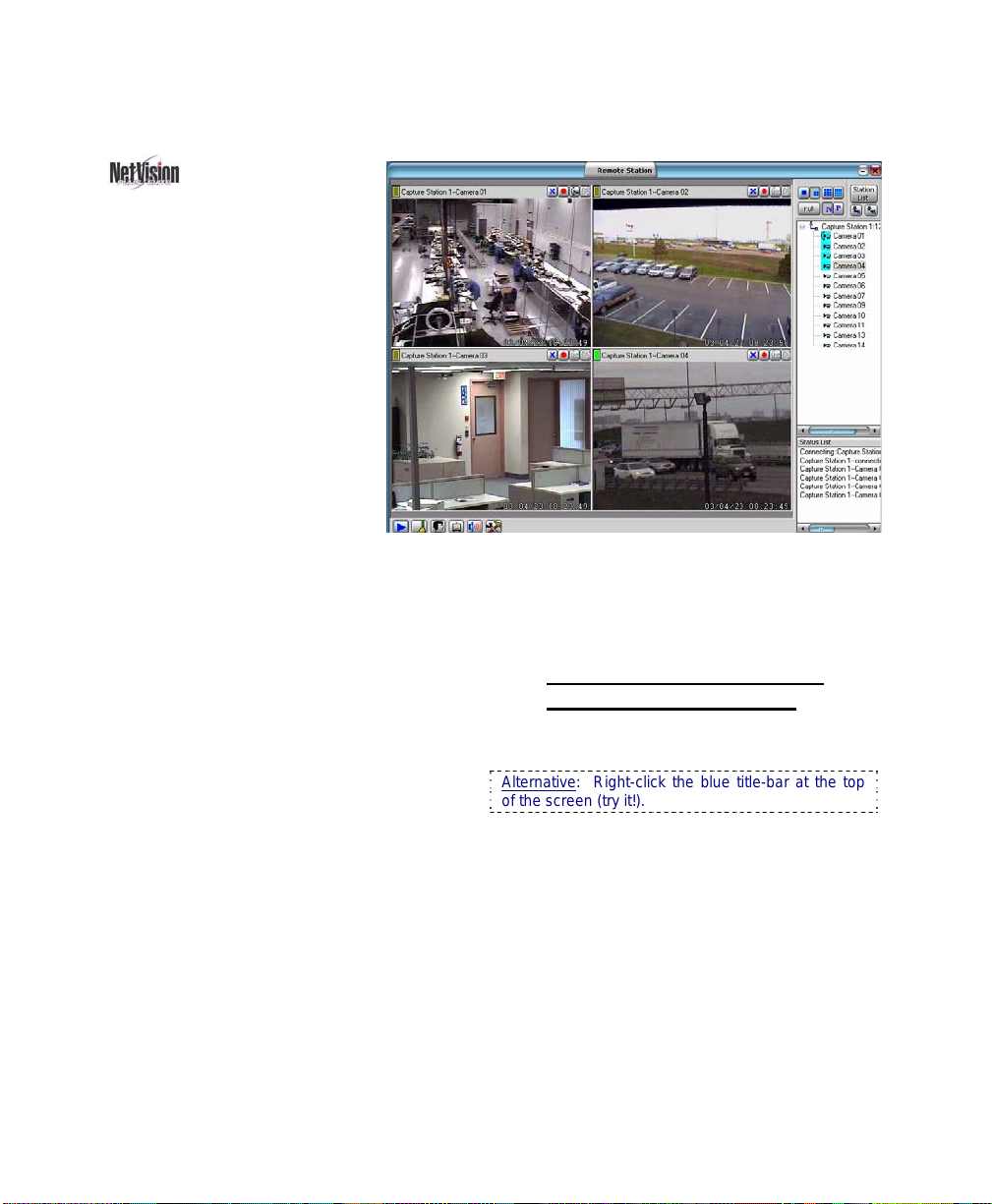
4.1 Remote Surveillance Station Desktop................................................................
4.2 Video Server Desktop.........................................................................................
4.3 Communications / Server Modules (Video Server) ............................................
Common / Daily Tasks ..............................................................................................................
5 Starting your Software and Logging In.......................................................................
Logging Out, Changing Operators, or Shutting Down......................................
6 Alarm / Reporting Features and 'Chatting' .................................................................
6.1 System I/O Primer.............................................................................................
6.2 Responding to Alarm Alerts..............................................................................
6.3 Responding to Alarm-Alert Email.....................................................................
6.4 Alarm / Recording Status Indications at a Video Server ..................................
6.5 Chatting On-line with a Video Server................................................................
7 Playing or Downloading Video Recordings................................................................
7.1 Overview--Types of Playback...........................................................................
7.2 Playback--Technical Details .............................................................................
7.3 Synchronized Playback (v2.3 SP2) ..................................................................
7.4 Video Search (v2.3 SP2) ..................................................................................
7.5 Searching for Motion.........................................................................................
7.6 Working with the Playback Screen...................................................................
7.7 Viewing and Printing 'Snapshots'......................................................................
7.8 Working with the File List..................................................................................
7.9 Quad Playback..................................................................................................
7.9.6 The Utility Screen (Quad Playback) ....................................................
7.10 Server Management--Identifying Remote Servers for Playback......................
8 Viewing Live Cameras................................................................................................
8.1 Viewing Cameras from a Remote Station ........................................................
8.2 Viewing Cameras at a Video Server.................................................................
8.3 Changing a Camera's View (Pan/Tilt/Zoom) ....................................................
8.4 Monitoring Cameras via TV (Spot Monitor) ......................................................
9 Recording Camera-Views...........................................................................................
9.1 Recording at a Remote Station........................................................................
9.2 Recording at a Video Server.............................................................................
1
2
4
4
6
6
7
8
9
10
11
12
12
12
14
15
16
17
17
17
18
20
22
24
26
27
30
34
35
37
37
38
40
43
44
44
45
21-0400E v2.3.3 (2006.12) © 2006 CSG Security Inc. / Sécurité CSG Inc. i
Page 4

System Administration and Maintenance............................................................................. 47
10 Tasks Applicable to Remote Stations and the Video Server......................................
10.1 PC Date and Time ............................................................................................
10.2 Checking your Software Version ......................................................................
10.3 Introduction to Video File Management (Filekeeping and Housekeeping) ......
10.4 To Allow Using a Blank CD
(Roxio - Easy CD Creator 5 basic with DirectCD) ..............49
10.5 Filekeeping (v2.3 SP2) .....................................................................................
10.6 Housekeeping...................................................................................................
10.7 Automatic Video File Management (Self Housekeeping).................................
11 Tasks Performed at the Video Server Only................................................................
11.1 Video Server Users and Passwords.................................................................
11.2 Remote Users and Permissions (+ HTTP server port).....................................
11.3 Viewing a List of Motion-Detection Alarms.......................................................
11.4 Backing Up or Restoring Configuration Settings..............................................
11.5 Viewing Changes Made through the "Utility" Menu..........................................
11.6 Viewing Remote User Sessions .......................................................................
System Configuration.............................................................................................................
12 Configuration Introduction ..........................................................................................
13 Remote Station Configuration ....................................................................................
13.1 Remote Stations: Basic Set-up.......................................................................
13.2 Setting Up the Alarm Alert Receiver.................................................................
13.3 Station List (Identifying the Video Servers) ......................................................
14 General Video Server Settings...................................................................................
14.1 Startup / Logoff Options....................................................................................
14.2 Miscellaneous Settings.....................................................................................
14.3 Setting Video Playback Sessions to be Logged...............................................
15 Alarm / Reporting Settings..........................................................................................
15.1 Enable/Disable Alarm Alerts or E-Mail .............................................................
15.2 Set Up the Alarm Alert Caller............................................................................
15.3 Auto Alarm Display (v2.3 SP2).........................................................................
15.4 Set Up Alarm Overlays (v2.3 SP2)...................................................................
16 Camera, Audio, and PTZ Settings..............................................................................
16.1 Set up Cameras and Titles...............................................................................
16.2 Cameras to Appear in Sequential Viewing.......................................................
16.3 Pan/Tilt/Zoom Activation and Set Up................................................................
16.4 Show Date and Time in Video Image (Time Stamp)........................................
16.5 Enable Audio for Specific Cameras..................................................................
16.6 Setting the Sound Level....................................................................................
16.7 Remote Audio Monitoring.................................................................................
48
48
48
48
50
53
54
57
57
58
60
61
61
62
63
64
65
65
66
67
68
68
68
69
70
70
72
74
75
77
77
78
79
80
81
81
82
ii NetVision Plus/Elite and Micro DVR v2.3 SP2 User's Guide 21-0400E v2.3.3
Page 5

17 Recording and Playback Settings...............................................................................
17.1 Video Setup (in DSR Configuration).................................................................
17.2 Recording Setup (in DSR Configuration).........................................................
17.2.1 Drive Usage ...............................................................................
17.2.2 File ..............................................................................................
17.2.3 Codec .........................................................................................
17.2.4 Priority ........................................................................................
17.2.5 Misc. ...........................................................................................
17.3 Resolution and Recording Mode ......................................................................
17.4 Frame Rate for Recording................................................................................
18 Scheduled and/or Alarm-Triggered Recording...........................................................
18.1 Introduction to Automated Recording...............................................................
18.2 Schedules for Recording and/or Motion Detection...........................................
18.3 External Sensors and Recording Duration.......................................................
18.3.1 Recording Mode for External Alarms..............................................
18.4 Setting up Pre-Alarm Recording.......................................................................
18.5 Setting up Video Motion-Detection...................................................................
Software Installation and Network Set Up............................................................................
19 PC Requirements .......................................................................................................
19.1 Video Server PC Reference .............................................................................
19.1.1 PC, Memory, Operating System.....................................................
19.1.2 Additional Drives.............................................................................
19.1.3 Microphone and Speakers..............................................................
19.1.4 Items Typically Done at the Factory................................................
19.2 Remote Station PC Requirements....................................................................
19.2.1 Processor (CPU).............................................................................
19.2.2 Memory (RAM)................................................................................
19.2.3 Operating System ...........................................................................
19.2.4 Video Card and Monitor ..................................................................
19.2.5 Hard Drive (Remote Stations).........................................................
19.2.6 Other Drive(s)..................................................................................
19.2.7 Sound Card and Speakers..............................................................
19.1.5 Windows XP with Service Pack 2 (WinXP-SP2).............................
20 Software Installation or Upgrade................................................................................
20.1 Installing or Upgrading the Remote Station Software.......................................
20.2 Reinstalling or Upgrading the Video Server Software......................................
21 Network and Connectivity Issues ...............................................................................
Network Usage ...............................................................................................101
84
84
84
84
85
85
85
86
87
87
88
88
88
90
90
91
92
93
94
94
94
94
94
94
95
95
95
95
95
95
95
95
95
96
96
97
98
21-0400E v2.3.3 (2006.12) © 2006 CSG Security Inc. / Sécurité CSG Inc. iii
Page 6

Reference Topics ................................................................................................................. 103
22 Using the Small Remote Module..............................................................................
23 Remote Configuration...............................................................................................
24 The WatchDog Feature............................................................................................
24.1 Introduction.....................................................................................................
24.2 Using the Watchdog Feature..........................................................................
24.3 Setting up the Watchdog Feature...................................................................
24.4 Hardware Watchdog Option ...........................................................................
24.4.1 Status LEDs..................................................................................
25 Hardware Reference ................................................................................................
25.1 Capture Board Reference...............................................................................
25.2 Camera and PTZ Reference...........................................................................
25.3 Wiring Reference............................................................................................
26 Troubleshooting........................................................................................................
27 Using the ATM Interface Option...............................................................................
27.1 Introducing the ATM Interface Option.............................................................
27.2 Topics Covered Elsewhere:............................................................................
27.3 Viewing ATM Cameras...................................................................................
27.4 Recording ATM Camera Images....................................................................
27.5 Playing ATM Video Recordings......................................................................
27.6 Additional Options (the right-click menu).......................................................
27.7 Viewing and Printing 'Snapshots' ...................................................................
28 Working with the Older Playback Engines ...............................................................
29 Viewing Cameras through a Web Browser ..............................................................
30 Setting up an IP Camera or Video Server module (v2.3 SP2).................................
31 Panoramic Video Surveillance--PVS (v2.3 SP2)......................................................
Index .......................................................................................................................................
104
106
107
107
107
107
109
110
110
110
111
115
119
120
120
120
120
120
121
123
123
124
133
137
141
145
iv NetVision Plus/Elite and Micro DVR v2.3 SP2 User's Guide 21-0400E v2.3.3
Page 7

Copyrights and Trademarks
™ NetVision and Micro DVR are trademarks
of CSG Security Inc. / Sécurité CSG Inc.
™ Pentium is a trademark of Intel Corporation
™ ® Microsoft, Windows, Windows 2000, and
Windows XP are trademarks or registered
trademarks of the Microsoft Corporation.
™ ImmerVision and IMV1 are
trademarks or registered
trademarks of ImmerVision Inc.
© Copyright 2006 CSG Security Inc.
CSG Inc. All rights reserved.
/ Sécurité
Disclaimer
All software, firmware, drawings, diagrams,
specifications, catalogues, literature, manuals
and other supplied materials shall constitute
the proprietary information of the
manufacturer. In the interests of ongoing
improvement in quality and design, we reserve
the right to change product specifications
without prior notification.
Attention: Physical alteration of hardware
components or removal of electrical devices
may void warranties, and/or affect radiofrequency and electromagnetic emissions.
This document is not to be copied, decompiled, or re-distributed in any form without
prior written consent.
© Copyright 2006 CSG Security Inc. / Sécurité
CSG Inc.
21-0400E v2.3.3 (2006.12) © 2006 CSG Security Inc. / Sécurité CSG Inc. v
indicates a topic that pertains to NetVision Plus
and Elite systems only
(not the Micro DVR).
The NetVision logo
Page 8

#
vi NetVision Plus/Elite and Micro DVR v2.3 SP2 User's Guide 21-0400E v2.3.3
Page 9

Welcome to NetVision
21-0400E v2.3.3
Welcome
Common Admin Config Install Tech-Ref
1
Page 10

1
System Overview
1.1
System Overview:
Netvision™ is a remote digital
video surveillance capture and
reporting system accessible by
LAN/WAN, the Internet, or through
a dial-up networking connection.
The two main components of the
system are the Video Server (with
cameras) and remote stations.
The Video Server collects and
digitally records video input from
video cameras and allows viewing
it at remote surveillance stations
using an IP link (LAN/WAN,
internet, or dial-up networking).
Note: Due to speed and reliability
considerations, dial-up connections are
NOT recommended. Use a faster
connection if you have a choice.
Video Server Models: Different
NetVision Video Servers are available,
supporting 4, 8, or 16 cameras.
1.2
Remote surveillance Stations are
video receivers that function as monitoring
consoles and enable a variety of
administrative, alarm and monitoring
functions. Remote monitoring tasks can
be carried out from anywhere you have
access to your network, the internet, or a
telephone.
The Video Server includes a computer, video
capture board(s), cameras, and software. Remote
surveillance stations include software typically
running on an existing/locally sourced Windows PC.
2 NetVision Plus/Elite and Micro DVR v2.3 SP2 User's Guide 21-0400E v2.3.3
Additional components include:
• Video cameras (up to 16--using four capture
boards). Any of them can include PTZ
support.
Eight ports/PTZ protocols are supported, plus PTZ-
cascading (e.g., Canon VC-C4).
• Input / Output wiring harness;
• Microphone(s) for audio support at
camera(s)--can be monitored at remote
stations as well.
Tip: Current video server units typically include up
to 5 audio inputs.
Related: 25.1 Capture Board Reference
Page 11

1.3
NetVision Software:
• Netvision (Video Server): View and record
up to 16 cameras at a time, plus
access/support for all other features, and
system configuration;
• Remote Station: Integrated remote
viewer and playback software. View and
record up to 16 cameras at a time from
various Video Servers. Play up to 4 video
recordings at a time. Chat with a Video
Server. Respond to alarm alerts. Control
PTZ cameras. Perform file maintenance
(housekeeping) tasks.
• Remote Module: View and record 1 camera
at a time, with access to playback utility and
other features.
Related Topics: 22 Using the Small Remote Module
• Video Playback (local and remote): Select a
Video Server and camera. Then, select
file(s) from a list, and play up to 4 at a time.
(manually, or sequential / continuous).
21-0400E v2.3.3
Welcome
Common Admin Config Install Tech-Ref
3
Page 12

2
Intended Audience and Required Knowledge
Sections pertaining to common tasks require
only a basic knowledge of using MS Windows.
For example, you should be familiar with how
to:
• Double-click, right-click, and drag-and-drop
items in MS Windows.
• Select or enter values in an on-screen form,
and select [OK] when finished.
• Respond to general/confirmation prompts.
Although the technical sections have also been
written with usability and simplicity in mind, the
procedures discussed there require a better
familiarity with both MS Windows, and
networking environments. For example:
• Being comfortable configuring more
technical features, and using the Windows
"Control Panel";
• How to get to a DOS/Command prompt
(e.g., to 'ping' an IP address).
Network Reliability: Since this system
works through your network, any problems
with the network and/or permission issues
may block communications and/or cause
features to be unavailable.
The reliable operation of your network is the
responsibility of your network administrator.
3
Feature Overview
Briefly, the NetVision system supports:
• Local and remote security via local and
remote user passwords and permissions;
• Extensive camera viewing and recording
features including: Local and remote
viewing and recording of up to 16 cameras;
Sequential camera viewing; Local and
remote control of PTZ cameras;
•
Support for IP cameras and
Network Video Servers allowing access to
cameras virtually anywhere in the world.
PTZ is also supported (for one protocol at a
time).
•
Supports 360° blindspot-free
viewing through ImmerVision IMV1 lenses
and the Panoramic Video Surveillance (PVS)
option.
• Camera images can include a date/time
stamp, and up to three custom titles;
•
Four video playback methods are
provided (v2.3 SP2):
+ Sync Playback (server/local files only):
Synchronized videos for all cameras at a given
time.
+ Video Search: • Search and playback files for a
desired server, camera, and time-range. • Further
search for motion within video clips. • Supports
downloading, file mgt. and saving individual
frames.
+ Quad Playback: Older playback engine.
+ 360 Playback (optional): Same screens as Video
Search, plus a control for panoramic processing.
• You can search for motion within video files,
including separate search and playback of
regular video recordings vs. backed up files
(CD, etc.).
• 'Snapshot' images can be taken from
recorded videos for printing or archiving.
(Printouts can include header, disclaimer,
and comment text.);
• Local and remote users can be limited to
specific cameras if desired;
• NetVision Plus and Micro DVR units support
up to 120fps (NTSC) or 100fps (PAL) on a
16 camera system. NetVision Elite systems
support up to 240fps (NTSC) or 200fps
(PAL) with 16 cameras;
• TV-out (spot monitor) functionality is
included for monitoring individual cameras
manually, in sequence, or when an alarm
occurs (external input or video motiondetection).
4 NetVision Plus/Elite and Micro DVR v2.3 SP2 User's Guide 21-0400E v2.3.3
Page 13

• NetVision Video Servers will include up to
five audio inputs—allowing audio to be
included with camera images and monitored
at authorized remote stations. (Systems
include a built-in sound card with
microphone jack, plus up to 4 line-level
audio inputs (on video capture boards, or an
optional 4-input audio board).
•
Audio can be monitored at remote
stations. This allows sounds associated with
a camera to be heard (and included in
recordings). This also allows an operator to
'broadcast' verbal instructions to remote
stations that are 'on-line'
microphone; controlled through remote user
permissions)
.
(via PC or camera
• Each camera can be triggered to auto-record
by an external sensor, or motion being
detected in the camera's view (configurable
including detection zones). Each camera
can also be set for ‘pre-alarm’ recording so
the scene is available showing up to 300
seconds before the alarm occurred.
• Motion sensing and/or recording can be
scheduled to occur at specific times.
(Recording can also be done manually, at Video
Server PCs and remote stations.)
•
Alarms (external sensors, video
motion detect, and/or video/signal lost—
where applicable) can:
+ Trigger a camera to display automatically (V2.3
SP2)
+ Trigger an associated PTZ camera to jump to a
pre-defined PTZ preset position
+ Signal a remote surveillance station (with or
without: A custom sound being played; 5-10
frames being displayed; The live camera being
auto-displayed, and/or; The camera being autorecorded.)
+ Signal an e-mail recipient (with or without a
'snapshot' image).
+ Activate special "Alarm Overlay" subtitles (v2.3
SP2).
• Alarms can trigger external device(s)
through one of three built-in outputs (one for
external sensors triggered, one for video
motion-sense, and one for either/both).
•
Netvision users can 'chat' on-line
with Video Server operators.
• The following items can be logged at a Video
Server:
+ Motion-detection and video lost alarms that occur;
+ Changes being made by operators using the
[Utility] menu;
+ Remote video playback sessions.
+ HTTP server activity (v2.3 SP2).
• The watchdog feature causes the Video
Server to restart automatically if the
Netvision software stops responding for a
pre-set duration (60-250 sec.).
With the hardware watchdog option, the Video
Server will be restarted in the event of MS Windows
'hanging' or 'crashing' as well.
• Built-in HTTP server;
• Web/browser-based viewing of camera
images, controlling PTZ cameras, and
recording remotely is provided through the
Webcam and/or WebView features.
• Remote (browser-based) configuration of
many items including motion detection set
up;
• Selectable recording CODEC (compression
and file-type) at Video Server PCs and
remote stations;
• Video files are encoded to help allow the
detection of image tampering.
•
SiteWatch™ software allows
monitoring the status of NetVision Video
Servers remotely.
• File management tasks can be performed
manually, or automated and scheduled
through the “Self-Housekeeping” feature.
+ (v2.3 SP2): New "Filekeeping" feature
allows viewing or adding a remark, plus
previewing, downloading, and maintenance
functions.
21-0400E v2.3.3
Welcome
Common Admin Config Install Tech-Ref
5
Page 14
4
Your NetVision Desktop
4.1
Remote Surveillance Station Desktop
The Main Window: Displays
selected camera views (one or
four);
Right-Hand Side of the Display:
This includes these items:
• Video format selector ([N] for NTSC
or [P] for PAL);
• Screen mode selector (1, 4, 9, or
16 camera/views);
• [ Full ]: Expands the camera area
to fill your whole screen (Press Esc
to cancel this);
• Video Server list and connection controls;
• Status / event list.
The Toolbar (bottom of the screen): This
includes:
• Play Back: Allows playing previously
captured videos, and capturing / printing
individual frames.
• HouseKeeping: Allows performing file
management and hard-drive maintenance
tasks;
• Alarm Alert: Allows viewing alarm alerts
sent from a Video Server (triggered by an
external sensor, video motion sense, or
video/signal-lost detection);
• Chat: Allows sending and receiving text to
alert or collaborate on-line with other
NetVision users;
• Audio Monitor: Allows remote stations to
monitor audio from Video Servers equipped
with a microphone (associated with a
camera);
• Utility
4.1.1
(tools symbol): Allows configuring some
auto-reconnect parameters, plus the
recording CODEC (compression and filetype);
If you Wish to Minimize the
Remote Station Desktop
Click the minimize button in the top right corner
of the screen.
Alternative: Right-click the blue title-bar at the top
of the screen (try it!).
6 NetVision Plus/Elite and Micro DVR v2.3 SP2 User's Guide 21-0400E v2.3.3
Page 15

4.2
Video Server Desktop
The Main Window: Displays
selected camera-views (from 1 to all
16 at-a-time);
Tip: A hard-disk usage indicator appears
at the bottom of the screen.
"Display" Selections: The upperright portion of the screen allows you
to:
• Select the number of camera/views
(or 'groups' of cameras) to be
visible at one time. (Try it!);
• Set the screen to seq-
uentially step through
the cameras / views;
• Select individual cameras to view
on-screen (1 - 16).
"Recorder" Selections: The middle righthand portion of the screen allows you to:
• Manually start / stop recording desired
camera view(s).
(individual camera(s), or all at once with
[ Record All ] ). With instant-recording,
double-clicking a camera-view starts the
recording.
Related Topics: 6.4 Alarm / Recording Status
Indications (Camera Number Colours);
17.2.5 Misc. (see "Instant Recording")
4.2.1
Large Buttons, Bottom-Right
Corner:
• [Logon] / [Logoff]: Allows an operator to
log in (to gain access to the system), or log
off when they are finished;
• [Utility]: Provides access to a number of
system settings, and maintenance/filemanagement tasks;
• [Playback]: Allows playing previously
captured videos, and capturing / printing
individual frames.
• [Full Scr]: Expands the active
camera/view(s) to fill the entire screen.
Tip: Right-click the screen once to return to normal
viewing.
• [Exit]: Allows shutting down the system.
Note: as this will stop all camera monitoring and
recording for this Video Server, you will be
prompted to confirm your intentions. You must be
logged in to use this (may require a "Supervisor"
login).
4.2.2
If you Need to Minimize the
Video Server Desktop
While logged in, you can minimize the Video
Server software by right
portion of the desktop (i.e., outside of any
buttons or display areas), and selecting
"Minimize".
If this feature is not available: This feature can be
turned on and off.
See: 14.2 Miscellaneous Settings
-clicking any fixed
21-0400E v2.3.3
Welcome
Common Admin Config Install Tech-Ref
7
Page 16

4.3
Communications / Server Modules (Video Server)
WebView
video server. Related
through a Web Browser
: The ‘WebView’ feature also uses the
: 29 Viewing Cameras
You'll notice some items on the task bar at
a Video Server when the NetVision
software is running.
Alarm Alert Caller: Manages the
•
sending of alarms to a remote surveillance
workstation;
Related Topics:
15.2 Set Up the Alarm Alert Caller;
6.2 Responding to Alarm Alerts (Remote Station)
• Alarm Alert Email Sender:
Manages the sending of alarm notifications
to e-mail recipients;
Related Topics:
6.3 Responding to Alarm-Alert Email
15.1 Enable/Disable Alarm Alerts or E-Mail
• Playback Server: Allows remote
surveillance stations to playback previously
recorded video sequences;
Related Topics:
7 Playing or Downloading Video Recordings
28.1 The Video Playback Feature (Micro DVR)
• PTZ Server: Allows remote surveillance
stations to remotely control camera-views
(Pan/Tilt/Zoom);
Related Topics:
8.3 Changing a Camera's View (Pan/Tilt/Zoom);
16.3 Pan/Tilt/Zoom Activation and Set Up
• Search Engine Server: Allows efficient
local and remote searching of video files;
Related Topic:
7 Playing or Downloading Video Recordings
28.1 The Video Playback Feature (Micro DVR)
• Watchdog: This causes the Video Server to
restart automatically if the NetVision
software stops responding for a pre-set
duration (60-250 sec.);
Tip: A hardware watchdog option is available as
well (for protection against MS Windows crashing
or 'hanging').
Related Topics: 24 The Watchdog Feature
• Audio Server: Allows remote
stations to monitor audio from Video Servers
equipped with a microphone (associated
with a camera);
Related Topics: 16.7 Remote Audio Monitoring
• DSR_Relay Server: Allows remote users
with access to the Internet to perform many
configuration tasks using their Web browser;
Related Topics: 23 Remote Configuration
• Webcam Server (hidden): This allows
using the WebCam feature to view camera
images through a web browser.
Related: 29 Viewing Cameras through a Web
Browser
• Chat Server: Allows remote
NetVision users to chat with Video Server
• USB Alarm IO Server: Future use;
------------------------------
------------------------------
operators;
Related Topic:
6.5 Chatting On-line with a Video Server
Remote_Users: The remote users who will be
able to access specific features can be set up
as desired.
• Video Server: Allows remote surveillance
stations to view cameras connected to a
Related Topics: 11.2 Remote Users and Permissions
(+ HTTP server port)
Video Server;
Related Topics: 8 Viewing Live Cameras
8 NetVision Plus/Elite and Micro DVR v2.3 SP2 User's Guide 21-0400E v2.3.3
Page 17

Common / Daily Tasks
21-0400E v2.3.3
Welcome
Common
Admin Config Install Tech-Ref
9
Page 18
5
Starting your Software and Logging In
5.1
Remote Station: Start-up and Logging In
5.1.1
Power Up and Windows Log In
Ensure your PC is powered up, and log into
your MS Windows as usual.
5.1.2
Starting the Remote Station
Software
Tip: Check the Windows task-bar to see if the
remote station software is already running.
From the Windows Start menu, select
Programs, NetVision, and Remote
Station.
5.2
Video Server: Start-up and Logging In
5.2.1
Power Up and Windows Log In
Video Servers typically come pre-set to start
up automatically after a power failure and
restoral (including automatic Windows log in).
To start a Video Server the first time, or after a
manual shut-down, look for a power switch on
the back (turn this on), and another one on the
front (push on, and release).
Network Access: For a new Video Server, contact
your network administrator to have the Video Server
PC given login privileges on your network.
Starting the Remote Module Software: For details
on starting and using the remote module software,
refer to:
Related Topics: 22 Using the Small Remote Module
5.1.3
Logging in At a Remote Station
When you start the remote station software,
you will be prompted for a username and
password. These are passed to the specific
Video Server during the connection process.
Tip: Press Tab in between, and Enter (or OK)
when finished.
Notes: User names, passwords, and allowed
permissions are set up at each Video Server.
Video Servers can also provide free access to
remote users (although you must enter a sample
username and password after starting the remote
station software).
Usernames are also referenced when managing
remote user connections from a Video Server.
With the small remote module software, you enter
your name and/or password only when connecting
(where applicable).
5.2.2
Re-Starting the Video Server
Software (only)
If the NetVision software is shut down at a
Video Server, you can restart it as follows:
From the Windows Start menu, select
Programs, NetVision, and NetVision.
Auto-Startup: Video Servers typically come pre-
set to have the NetVision software start
automatically whenever the PC is re-started (and
after a power failure).
Quick-Access: Similarly, you can provide easier
access to any program or Control Panel item by
dragging its shortcut to the Windows desktop
(anywhere) or to the taskbar (near the left side).
Security Key Not Found / Restricted Mode error:
This means only that your Video Server supports
more capture boards than are presently installed
(and/or you are trying to use an unsupported type of
capture board).
10 NetVision Plus/Elite and Micro DVR v2.3 SP2 User's Guide 21-0400E v2.3.3
Page 19
5.2.3
Logging in At a Video Server
Video Servers support two types of local users:
Supervisors, and Operators.
At a Video Server, click [Logon] on the main
screen. Then, enter a username and
password that has been registered.
Tip: Press Tab in between, and Enter (or OK)
when finished. Note: After restarting the software,
[Logon] may not be available for a minute or so.
Default Video Server User Names and
Passwords
User name Password Permissions
Super -- Access to everything.
Operator -- Everything except
Note: These passwords do NOT pertain to remote
stations.
Related Topics: 11.1 Video Server Users and
Passwords
5.2.4
If you Need to Minimize the
configuration tasks.
Video Server Desktop
While logged in, you can minimize the Video
Server software by right
portion of the desktop (i.e., outside of any
buttons or display areas), and selecting
"Minimize".
If this feature is not available: This feature can be
turned on and off.
See: 14.2 Miscellaneous Settings
-clicking any fixed
5.3
Remote Station: Logging Out, Changing Operators, or Shutting Down
At a surveillance station, there is no need to
leave the software running with no one logged
in, so you'll be logged out automatically when
you shut down the software.
To shut down the software, click, the [X] in the
upper right corner of the screen.
If a new operator wishes to log in, they can
start the software and login as usual.
5.4
Video Server: Logging Out, Changing Operators, or Shutting Down
To logout at a Video Server, click [Logoff]. If
a new operator wishes to log in, they can click
[Logon] and enter their username and
password as usual.
To exit (shut down) a Video Server, click
[Exit]. Note: as this will stop all camera
monitoring and recording for this Video Server,
you will be prompted to confirm your intentions.
Note: The [Exit] button is available only when
you are logged in, and depending on the startup options, may be available only for
"Supervisors".
5.2.5
PTZ Control after Start-Up
The PTZ server has a delayed start-up to allow
Windows services to stabilize. (The PTZ
feature will not be available until 1 minute
(approx.)
Related Topics:
8.3 Changing a Camera's View (Pan/Tilt/Zoom)
16.3 Pan/Tilt/Zoom Activation and Set Up
21-0400E v2.3.3
after the Video Server is re-started.)
Welcome
Common
Admin Config Install Tech-Ref
11
Page 20

6
Alarm / Reporting Features and 'Chatting'
6.1
System I/O Primer
6.2
Video Servers support video motion
sensing (configurable including detection
zones), plus one physical sensor
6.2.1
associated with each camera. Both
features can trigger automatic recording,
and the system can be set to maintain
short recordings so the view of just before
motion was detected is available (prealarm recording).
Motion detection and/or video/signal-
lost detection can also:
• Trigger an email recipient, or;
• Cause a surveillance station to be alerted to
check a specific camera.
Three outputs are supported at each Video
Server for additional signalling. These can be
used to alert an alarm system, or to trigger a
self-powered device. One output activates
when motion is sensed in any camera view,
another when any external input is triggered,
and the third one activates on either (both) of
these conditions.
Tip: Inputs and outputs are supported through a
special wiring harness.
Related Topics
: 25.3 Wiring Reference
A NetVision Video Server can let one remote
station (plus multiple e-mail addresses) know
when an alarm occurs (external input tripped,
video motion-detection, or video-lost). These
are known as ‘Alarm Alerts’. A recording of the
scene will also be available at the Video Server
PC.
Related Topics:
13.2 Setting up the Alarm Alert Receiver
15.1 Enable/Disable Alarm Alerts or E-Mail
(Video Server);
15.2 Set Up the Alarm Alert Caller (Video Server)
'Alarm alerts' are viewed through the "Alarm
Alert Receiver".
To activate the Alarm Alert Receiver, start your
remote software, and click the Alarm Alert icon
(head/portrait) once.
The Alarm Alert Receiver can also be run on its
own:
Startup: Run Alarm Receiver.exe in the folder for
your NetVision software (under C:\Program
Files\Digital Surveillance Recorder\...).
Shutdown: Right-click the Alarm Alert Receiver
symbol (head/portrait) on the right-hand side of the
Windows task bar, and select Exit.
Responding to
Alarm Alerts
Introduction / Activate the Alarm
Receiver
12 NetVision Plus/Elite and Micro DVR v2.3 SP2 User's Guide 21-0400E v2.3.3
Page 21

6.2.2
Using the Alarm Receiver
When a new alarm comes in from a
surveillance station, the alarm alert receiver
will open automatically showing the Video
Server (IP address) and camera number. The
receiver will continue beeping until you select
the alarm message (camera number), and
click [Acknowledge].
Viewing Previous Messages Manually: To open the
alarm alert receiver manually, right-click the Alarm
Alert Receiver symbol (head/portrait) on the righthand side of the Windows task bar, and select
Restore.
Tip: These alerts may also include a custom sound
(WAV file available on your PC). This sound will
play once each time an alert is received.
6.2.3
Working with the Image Loop,
Auto Camera Display, and Auto
Recording Features
The alarm alert feature can be set up at each
remote station to:
• Repeatedly show 5 - 10 frames from the
camera;
• Display the live camera automatically;
• Record the live camera automatically for a
pre-set duration.
These items will appear in separate windows
which can be set to close automatically, or stay
open until you close them. (Live camera
images will appear in the camera-viewer
window of the small remote module.
For additional information, review the next
topic ("Manually viewing..."). Everything after
the first sentence applies here as well.
Related Topics:
13.2 Setting up the Alarm Alert Receiver
6.2.4
Manually Viewing the
Associated Camera Image
To view the live camera image in a small
window, double-click the camera number at the
beginning of the message line. If prompted to
log in, enter a username and password that is
registered at the Video Server.
After checking the camera, be sure to respond
appropriately once you determine what's going
on. This may include calling the Police or
other security personnel.
To close the camera window, click the X in the top-
right corner. You will be prompted with "Do You
want to Clean up All Passwords?":
[Yes]: If the Video Server is set for remote
password protection, you'll have to enter your
remote user-name and password the next time you
use this feature.
[NO]: The Video Server will remember the last
password you entered.
Tip: You can also playback the recorded video file.
(see "Related Topics").
Notice: A video/signal lost indication can be due to
hardware failure, a bad connection or a power fault,
however, since it may be due to foul-play at the site,
it's often best to proceed with caution, and treat the
event as a break-in.
Also See:
7 Playing or Downloading Video Recordings;
22 Using the Small Remote Module
28.1 The Video Playback Feature (Micro DVR)
21-0400E v2.3.3
Welcome
Common
Admin Config Install Tech-Ref
13
Page 22

6.3
Responding to
Alarm-Alert Email
A NetVision Video Server can let one remote
station (plus multiple e-mail addresses) know
when an alarm occurs (external input tripped,
video motion-detection, or video-lost). The
email messages are known as ‘Email alerts’, or
‘Alarm-Alert Email’. A recording of the scene
will also be available at the Video Server PC.
Note: For this feature, an email service with some
type of instant notification is recommended.)
When you receive an ‘email alert’, take
note of the indicated Video Server (IP
address), camera, and time of the event.
Then, start your remote station software,
connect with the Video Server, and view
the indicated camera (and/or play the
recorded alarm video) as desired.
Be sure to respond appropriately once you
determine what's going on. This may
include calling the Police or other security
personnel.
Notice: A video/signal lost indication can be due to
hardware failure, a bad connection or a power fault,
however, since it may be due to foul-play at the site,
it's often best to proceed with caution, and treat the
event as a break-in.
Related Topics:
13.2 Setting up the Alarm Alert Receiver;
15.1 Enable/Disable Alarm Alerts or E-Mail
(Video Server)
14 NetVision Plus/Elite and Micro DVR v2.3 SP2 User's Guide 21-0400E v2.3.3
Page 23

6.4
Alarm / Recording Status Indications at a Video Server (Camera Number Colours)
6.4.1
Indications in the "Display" Area
(Top-right)
Red Line Above Camera Button: Video
motion-detection enabled (will auto-record
when motion is detected);
Green Line Above Camera Button: Video
motion sensing standing-by (e.g., outside of
scheduled alarm-monitoring times);
Green Camera Number: A camera that is
presently being displayed.
6.4.2
Indications in the "Record" area
(middle-right)
Different types of recordings are indicated by
the colour of each camera button:
• Red Camera #: Alarm/motion triggered
recording ;
• Light Blue Camera #: Pre-alarm recording;
• Yellow Camera #: Instant/manual
recording;
• Green Camera #: Scheduled recording.
Coloured lines above the camera buttons (in
the "Record" area):
Red Line: External sensor being monitored
for this camera--will record if 'tripped'
(and/or
camera #: External sensor only);
Green Line: External sensor monitoring
and/or pre-alarm recording standing-by (e.g.,
outside of scheduled alarm-monitoring times);
Related Topics:
8.1 Viewing Cameras from a Remote Station;
8.2 Viewing Cameras at a Video Server;
9 Recording Camera-Views;
18 Scheduled and/or Alarm-Triggered Recording
pre-alarm recording is in effect; White
21-0400E v2.3.3
Welcome
Common
Admin Config Install Tech-Ref
15
Page 24

6.5
Chatting On-line with a Video Server
Remote surveillance stations can use the text
'chat' feature to initiate a 'conversation' with a
Video Server.
Tip: You may need to use e-mail or the telephone
to first ensure that someone will be at the Video
Server.
6.5.1
Connecting and Sending
Messages from a Remote
Station
Tip: This is supported via dial up and/or internet as
well (you may need to 'launch' your connection
first).
Click the 'Chat' icon (bottom of the screen) to
open the chat window. Then enter (or select) a
Video Server IP address (or its name on the
network), and click [Logon].
If prompted for a user name and password,
enter these, and click [OK].
Note: If your name and password entries are
erased, this means they are not recognized by the
Video Server (chat server). Ensure you typed them
correctly. If they are still not accepted, contact the
Video Server and have your privileges set up for the
chat server.
If You are not prompted for a User Name and
Password: This means that either the Video Server
is set to give anyone access to the chat feature, or
your username and password entered when logging
into the remote station software have been
accepted.
To send a message, click within the 'message'
box, type your message, and click [Send].
When you see a response, repeat these steps
to send a response.
6.5.2
Responding to Chat Messages
(Video Server)
• Open the chat server: Right-click the 'Chat
Server' icon on the windows task bar, and
select Restore.
• Select (double-click) the desired user in the
connection list;
• Click within the 'message' box, type your
response, and click [Send].
To End a Remote User's Connection: Select the
user (double-click), and click [Terminate]. (If they
weren't finished, they can simply log on again.)
6.5.3
Saving a 'Chat' Session as a
Text File (remote station or
Video Server)
Click [Save]. In the next screen, set the
filename and location as desired, and click
[Save] again.
Related Topics:
11.6 Viewing Remote User Sessions;
11.2 Remote Users and Permissions
(+ HTTP server port)
16 NetVision Plus/Elite and Micro DVR v2.3 SP2 User's Guide 21-0400E v2.3.3
Page 25
7
Playing or Downloading Video Recordings
Micro DVR: Searching and playback using the Micro DVR product is covered separately.
Related Topics
: 28 Working with the Older Playback Engines
Surveillance (PVS) control enabled to allow
7.1
Overview--Types of
Playback
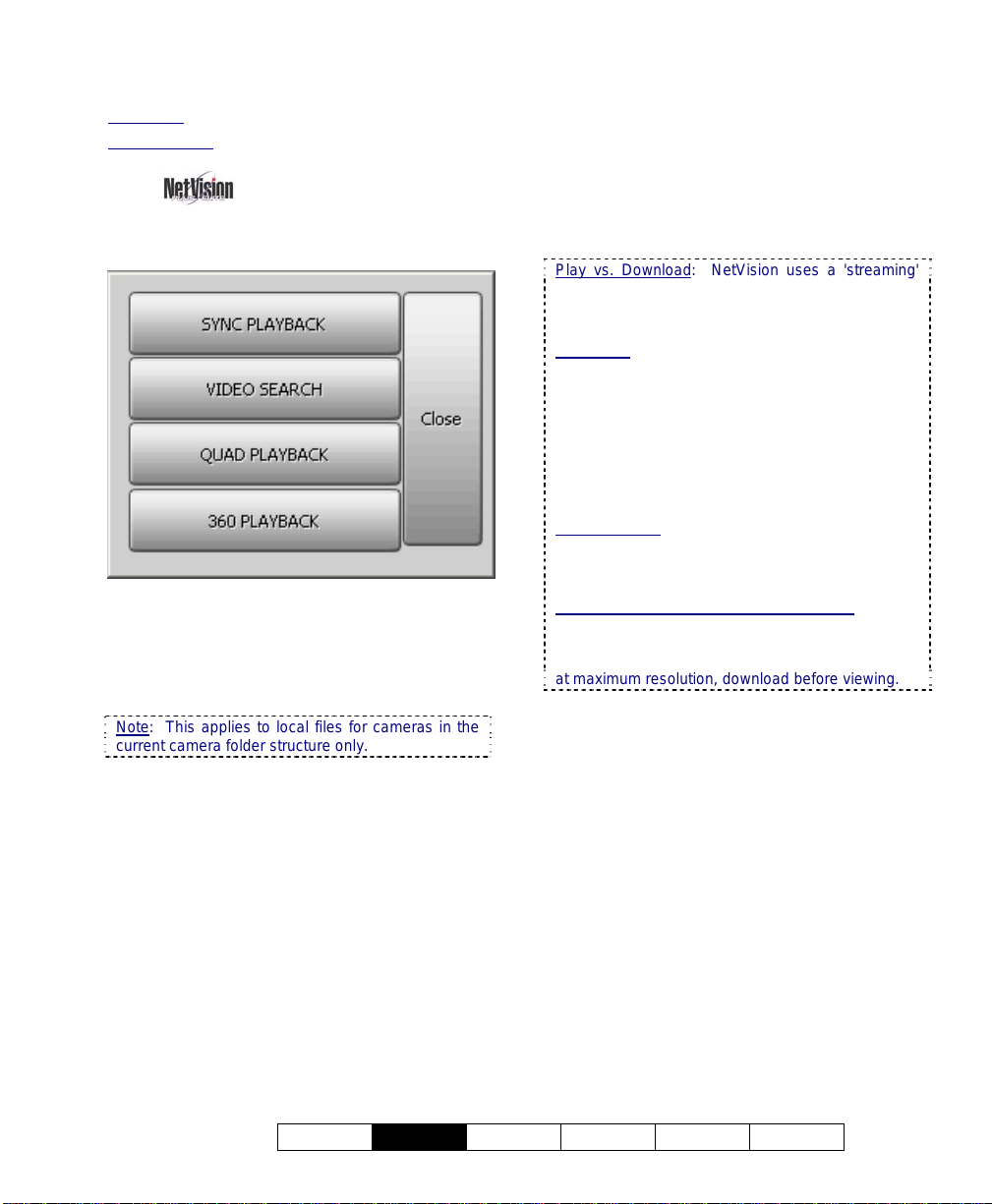
Four different playback methods are provided:
• Sync Playback (server/local files only): • Clips
for a desired time-period from up to 16
cameras on-screen at the same time.
• Allows file management including a 'tab' for
working with panoramic camera images.
7.2
Playback--Technical Details
Play vs. Download: NetVision uses a 'streaming'
playback approach--allowing remote videos to start
playing right-away (without having to be
downloaded 1st).
Exception: Due to extremely limited bandwidth,
streaming playback is NOT recommended
through a dial-up connection. Download
instead.
TechTip: Remote (streaming) playback provides
much less 'loading' on the Video Server than
playing the videos on the Video Server itself.
However, it is best to 'download' remote files, and
then play them locally (esp. for pause/resume, etc.)
Related Topics:
7.8 Working with the File List (v2.3 SP2)
10.3 Introduction to Video File Management
(Filekeeping and Housekeeping)
Remote Playback of ‘Super’ Recordings: When
recordings made at ‘Super’ resolution are played
back through a remote connection, they will never
appear at better than ‘High’ resolution. For viewing
at maximum resolution, download before viewing.
each camera.
Note: This applies to local files for cameras in the
current camera folder structure only.
• Video Search: • Search and playback files
for a desired server, camera, and timerange. • Further search for motion within
video clips. • Supports downloading and file
management for the selected camera.
• Allows saving single-frame snapshots.
• Quad Playback: • Search and playback
files for any 1-4 cameras from any server
(not synchronized). • Supports preview,
download, and playback. • Allows saving
single-frame snapshots.
• 360 Playback
(optional): Provides the same
features (and uses the same screens) as
Video Search, but with a Panoramic Video
21-0400E v2.3.3
Welcome
Common
Admin Config Install Tech-Ref
17
Page 26

7.2.1
Video Filename / Location
Reference:
Captured video files are stored under \dsrvideo\image on the specific PC, in folders for
each 'server' (PC name or IP address), camera
name, and date.
Exceptions: • Backed up files are placed in \dsr-
Backup\image on the drive selected during the
backup process; • 'Motion-found' files created by
the Smart Search feature are located under \dsr-
postmotion\image; • All files are placed in folders
for each 'server' (PC name or IP address), camera
name, and date.
Tips: • Videos are recorded as standard "AVI" (or
MPEG) files that can be played back using
NetVision, or any typical Windows media player
program; • You can minimize the playback window
by clicking [] in the top-left corner; • Similarly,
you can 'collapse' the playback and search screens
by right-clicking anywhere on the blue title-bar.
File-Type Reference: The first letter of the
filename, and the "Event" column (in the
File List screen) show the type of recording:
A / ALM: A motion / alarm-triggered recording;
P / PRE: A pre-alarm recording (immediately
before motion was detected);
R / REC: A manual / instant recording;
S / SCH: A scheduled recording.
7.3
Synchronized
Playback (v2.3 SP2)
7.3.1
Introducing "Sync Playback"
Synchronized playback allows video files from
multiple cameras during the same time period
to be viewed at the same time.
Scope: This feature is available only on video
server PCs. As well, this applies to local files for
cameras in the current camera folder structure only.
Remote Software: Due to sharing of resources, if
the remote software is run on the server PC, [Sync
Playback] will appear in its playback menu, but the
button will be non-functioning there.
7.3.2
Using "Sync Playback"
Locator: (Server PC), Ö[Playback],
Ö[Sync Playback].
1) The SyncSearch screen will open
automatically (on top of the
SyncPlayback screen). Select a date,
plus the type of recordings to search for,
and click [Search / Play].
Calendar: You can also use the pop-up calendar to
select a date: 1) Click the calendar symbol; 2) Use
the arrows to browse to the desired month; 3) Click
to select a day.
2) The SyncPlayback screen will appear.
If "Auto Play" is selected, the videos for
the earliest time on your selected date
will start playing automatically.
Not All Appear: Videos will play simultaneously only
for cameras with recordings at the specific time. If
one camera's recording starts before another one, it
will play by itself until the time index reaches the
other camera(s) files.
You can:
• Set the Display: Use the buttons near the top
right to select the number of cameras and
specific cameras to be shown.
• Control Playback: Use the playback controls
near the bottom-right. A speed control is on
the right.
• Move around in the Timeline: Use the slider
18 NetVision Plus/Elite and Micro DVR v2.3 SP2 User's Guide 21-0400E v2.3.3
Page 27

and controls near the bottom-left.
• To perform another
search, work with the file list, or process
filekeeping tasks, use the coloured buttons
on the right.
Videos Out-Of-Sync: Where a large number of
small recordings exist for each camera, it is
possible for the displayed videos to go out of sync.
If you notice this (per the displayed time in each
image), click the Restore button (bottom-right).
7.3.3
The SyncPlayback Screen
- Pause: Stops playing the video(s) and
stays at the present position in the file(s).
-
Stop: Stops playing the video(s) and
resets to the beginning of each file.
Right Side of the Screen
- Display Mode: Select 1, 4 or 16 camera
mode for Sync Playback (as applicable).
- Camera Number: Allows limiting the playback
to videos from specific cameras. Select the
desired ones. (Cameras must have recordings
on the selected day to be selectable.)
Camera Titles: The camera title will appear if you
'hover' your mouse cursor over a camera button.
- Speed: This sets the Playback Speed (relative
to the recorded speed of 1).
Operation:
- Set Start Time: This button brings up the
original SyncSearch screen where you can
select the Date and Events again.
Bottom of the Screen
- Date: Files recorded on your chosen day will
be loaded for playback.
- Time hh::mm::ss: Select your desired Start
time for the files.
- Seek File: Jump to the Previous or
Next file (as per the starting time from any
camera). This changes the Start Time to the
beginning of that file.
- Play: Starts playing the video clip(s) for
the selected start time.
Auto Play: This occurs automatically if "Auto Play"
is selected (9) near the bottom-right corner of the
screen.
21-0400E v2.3.3
Welcome
Common
Admin Config Install Tech-Ref
File List: Shows a list of files found in
-
your last search (i.e., available for playback).
Files can be marked for various "FileKeeping"
aspects using the Right-Click menu.
Related Topics:
7.8 Working with the File List (v2.3 SP2)
- File Keeping: Performs tasks (backup,
delete, etc.) for files marked in the file list using
the right-click menu.
Related Topics:
10.5 Filekeeping (v2.3 SP2)
- Auto Play: When selected (9) 'found' files
start playing automatically each time you select
"[Sync Playback], Ö[Search/Play]".
-
Restore: This returns you to full-screen
after having adjusted the height or width of the
window.
19
Page 28

Videos Out-Of-Sync: Where a large number of
small recordings exist for each camera, it is
possible for the displayed videos to go out of sync.
If you notice this (per the displayed time in each
image), clicking Restore will also correct this.
- Always on Top: When selected (pin
stuck in), this stops the SyncPlayback screen
from being hidden by any other programs.
7.4
Video Search (v2.3 SP2)
This section also applies to searching and
playback using [360 Playback].
360 Playback: This pertains to optional Panoramic
Video Surveillance (PVS).
Related Topics:
31 Panoramic Video Surveillance (PVS)
7.4.1
Introducing Video Search
Video Search:
• Allows you to search and playback files for a
desired server, camera, and time-range.
• Allows a further search for motion within
video clips.
• Supports downloading and file management
for the selected camera.
• Allows saving single-frame snapshots.
7.4.2
Using Video Search
Locator: [Playback], Ö[Video Search]
(or [360 Playback] ).
Remote Software: Click the coloured 'Play' button,
then select [Video Search] (or [360 Playback] ).
1) The Search screen will open
automatically (on top of the Playback
screen). Select from ALL search
parameters shown, and click [Start
Search]. (The number of 'found' video
files will appear onscreen.)
If Searching for Remote Files: You must first
select a server, and enter a username &
password that is valid for that server. Then,
click [Sign In] to connect.
Remote Servers: These are initially set up
under [Server Management].
Related Topic:
7.10 Server Management
2) Thereafter, you can further search for
motion within video files using [Motion
Search].
QuickSteps: • Click to select 'motion-detection'
zones and other parameters. • When ready, click
[OK].
Related Topic
7.5 Searching for Motion (v2.3 SP2)
:
3) In each case you can then open and
work with the file list (click [File List] ),
or start viewing the video clips directly
(click [Play] ).
Related Topic:
7.8 Working with the File List (v2.3 SP2)
3) To perform another search, click
the folder/binoculars symbol in the
playback screen, OR start over from the
playback menu. (Click the [X]
(top-right)
to close any screen that is in the way.)
20 NetVision Plus/Elite and Micro DVR v2.3 SP2 User's Guide 21-0400E v2.3.3
Page 29
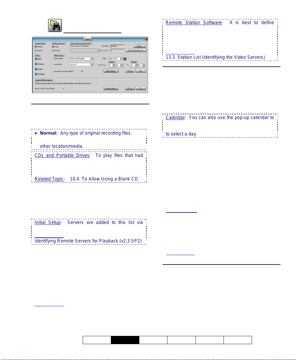
7.4.3
The Search Screen
Top of the Screen
- Playback File: Select the type of files to play
back (Normal or Backup files).
• Normal: Any type of original recording files.
• Backup: Files that had been backed up to some
other location/media.
CDs and Portable Drives: To play files that had
been backed up onto a CD or a portable drive,
ensure the CD or portable drive is accessible (and
formatted) before starting your search.
Related Topic: 10.4 To Allow Using a Blank CD
- Playback Server: Select whether you wish to
access local or remote files.
- Remote Server Information: For a remote
server, enter (or select) the server name or IP
address.
Initial Setup: Servers are added to this list via
[Server Management].
Related Topic: 7.10 Server Management-Identifying Remote Servers for Playback (v2.3 SP2)
- Username and Password: For a remote
server, enter a valid username and password as
needed to access the remote files.
- [Sign In]: Select this to connect with a remote
server to allow searching through its video files.
- Server Management: This allows setting up
remote servers to be selectable under "Remote
Server Information".
Related Topic: 7.10 Server Management-Identifying Remote Servers for Playback (v2.3 SP2)
Remote Station Software
remote servers through the [Station List] on the
desktop, since this information is automatically
shared with the [Server Management] screen (but
not the other way around).
Related Topic:
13.3 Station List (Identifying the Video Servers)
: It is best to define
Middle of the Screen
- Event: Select the types of recordings that you
wish to search for.
- Video Source: Select the desired server name
and camera (title).
- Date: Select the desired date for your search.
Calendar: You can also use the pop-up calendar to
select a date: 1) Click the calendar symbol; 2) Use
the arrows to browse to the desired month; 3) Click
to select a day.
- Time From and "To": Select the desired
starting time and end time for your search.
- [Start Search]: Select this to perform your
search. The number of 'found' video files will
appear onscreen (and be available to the [File
List] and [Play] functions).
- [File List]: This opens a list of files found by
your search, and allows: • Previewing files,
• Playing a file, and/or: • Selecting and marking
files for maintenance tasks.
Related Topics: 7.8 Working with the File List (v2.3
SP2)
10.5 Filekeeping (v2.3 SP2)
- [Play]: This opens the Playback screen with
your 'found' files loaded. If "Auto Play" is
selected there, the first file in the list will begin
playing automatically.
Related Topic:
7.6 Working with the Playback Screen (v2.3 SP2)
Bottom of the Screen
Optional Motion Search
This pertains to creating a new set of
temporary video files (after performing an initial
search) by 'looking' for motion within files.
- [Motion Search]: Select this to perform a
motion search. A small screen will appear to
allow setting up motion parameters. When you
21-0400E v2.3.3
Welcome
Common
Admin Config Install Tech-Ref
21
Page 30

click [OK], the search will execute. When it
finishes, you can go into its [File List], or [Play]
function as desired.
Attention: A motion search produces temporary
files that are intended to narrow down a search to
find a particular incident. When any new search is
performed, the last list of motion search files will be
lost. Be sure to take note of the camera/time
details, or immediately mark the desired motion
file(s) and copy them to another location.
Related Topics:
7.5 Searching for Motion (v2.3 SP2)
7.8 Working with the File List (v2.3 SP2)
10.5 Filekeeping (v2.3 SP2)
- [File List]: This opens a list of files found by
your motion-search, and allows: • Previewing
files, • Playing a file, and/or: • Selecting and
marking files for maintenance tasks.
Related Topics: 7.8 Working with the File List (v2.3
SP2)
10.5 Filekeeping (v2.3 SP2)
- [Play]: This opens the Playback screen with
your resulting motion files loaded. If "Auto Play"
is selected there, the first file in the list will begin
playing automatically.
Related Topic:
7.6 Working with the Playback Screen (v2.3 SP2)
7.5
7.5.1
Introducing "Motion Search"
Searching for Motion
After doing an initial Video Search, you can
further refine your search by searching for
motion within your file list. This creates a new
set of temporary video files for you to work
with.
7.5.2
Technical Information
Attention: A motion search produces temporary
files that are intended to narrow down a search to
find a particular incident. When any new search is
performed, the last list of motion search files will be
lost. Be sure to take note of the camera/time
details, or immediately mark the desired motion
file(s) and copy them to another location.
Related Topics:
7.8 Working with the File List (v2.3 SP2)
10.5 Filekeeping (v2.3 SP2)
Note: Because of their location, 'motion-found' files
cannot be backed up (only copied to another
location).
File Location: The motion search files are stored at
each specific server PC (even when searching
remotely) under: d:\Dsr-Postmotion\image\server
\camera\date\, where "d" is the drive letter specified
under "Recording Setup".
Related Topic: 17.2.1 Drive Usage
Remote Software: If doing a motion search through
the remote software for files on that same remote
PC, the drive containing the operating system is
used (typically "C:\...").
7.5.3
Using "Motion Search"
Prerequisite: Perform a search using
[Video Search] or [360 Playback].
360 Playback: This pertains to optional Panoramic
Video Surveillance (PVS).
Related Topic: 7.4 Video Search (v2.3 SP2)
7.6 Working with the Playback Screen (v2.3 SP2)
7.8 Working with the File List (v2.3 SP2)
31 Panoramic Video Surveillance (PVS)
Steps:
1) Go to: [Playback], Ö[Video Search] (or
360 Playback)
. The Search screen will
appear.
22 NetVision Plus/Elite and Micro DVR v2.3 SP2 User's Guide 21-0400E v2.3.3
Page 31
Remote Software: Click the coloured 'Play'
button, then select [Video Search] (or [360
Playback] ).
2) Select from ALL search parameters
shown, and click [Start Search]. When
it finishes, the number of found files will
be shown on-screen (and be available
to the [File List] and [Play] functions at
the bottom of the search screen).
If Searching for Remote Files: You must first
select a server, and enter a username &
password that is valid for that server. Then,
click [Sign In] to connect.
Remote Servers: These are initially set up
under [Server Management].
Related Topic:
7.10 Server Management--Identifying Remote
Servers for Playback (v2.3 SP2)
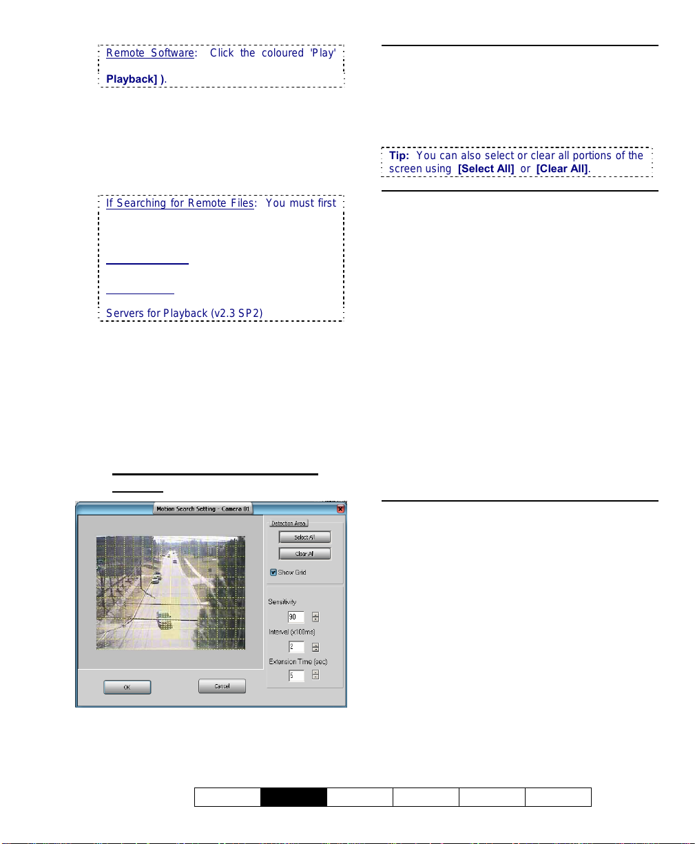
3) Click [Motion Search]. A small screen
will appear to allow setting up motion
parameters.
4) When you click [OK], the search will
execute. When it finishes, you can go
into the [File List], or click [Play] to start
playing the files.
7.5.4
The "Motion Search Setting"
Screen
Main Portion of the Screen
- With "Show Grid" selected, this area shows a
camera image with a grid of selectable squares
(motion-detection zones). Click the desired
areas of the frame that are to be checked for
motion.
Tip: You can also select or clear all portions of the
screen using [Select All] or [Clear All].
Right-Hand Side of the Screen
Detection Area
-
[Select All]: Selects all detection squares on the left;
- [Clear All]: Clears all detection squares on the left;
- Show Grid: This shows/hides a 'grid' to
indicate the selected 'motion-detection zones'.
- Sensitivity: This sets a relative threshold for
motion detection. Leave this as-is unless motion
is being detected falsely (or if it is not being
detected when it should).
- Interval (x100 ms): This sets how often the
camera-view will be checked for motion (i.e.,
every xx tenths of a second).
- Extension Time (sec): This sets how long the
resulting files will be—beyond the motiondetected portion (up to 30 seconds). With
intermittent motion, a smaller value can result in
a larger number of smaller files being produced.
21-0400E v2.3.3
Welcome
Common
Bottom of the Screen
- [OK]: Starts the motion search using your
selected parameters.
- [Cancel]: Cancels the motion search, and
ignores any changes you made in this screen.
Admin Config Install Tech-Ref
23
Page 32

7.6
Working with the
Playback Screen
7.6.1
Introduction
The Playback screen allows you to select and
view videos found through [Video Search], or
[360 Playback].
360 Playback: This pertains to optional Panoramic
Video Surveillance (PVS).
Related Topics:
7.4 Video Search (v2.3 SP2)
31 Panoramic Video Surveillance (PVS)
Also See:
7.3 Synchronized Playback (v2.3 SP2)
7.9 Quad Playback
28 Working with the Older Playback Engines
All files in the present File List will be available
to the Playback screen.
7.6.2
Technical Information
Play vs. Download: NetVision uses a 'streaming'
playback approach--allowing remote videos to start
playing right-away (without having to be
downloaded 1st).
Exception: Due to extremely limited bandwidth,
streaming playback is NOT recommended
through a dial-up connection. Download
instead.
TechTip: Remote (streaming) playback provides
much less 'loading' on the Video Server than
playing the videos on the Video Server itself.
However, it is best to 'download' remote files, and
then play them locally (esp. for pause/resume, etc.).
Remote Playback of ‘Super’ Recordings: When
recordings made at ‘Super’ resolution are played
back through a remote connection, they will never
appear at better than ‘High’ resolution. For viewing
at maximum resolution, download before viewing.
Related Topics:
7.8 Working with the File List (v2.3 SP2)
10.5 Filekeeping (v2.3 SP2)
7.6.3
Locator / What You can Do
Prerequisite: Perform a search using
[Video Search] or [360 Playback] (regular
search plus optional motion search, if desired).
Related Topics:
7.4 Video Search (v2.3 SP2)
7.5 Searching for Motion (v2.3 SP2)
31 Panoramic Video Surveillance (PVS)
Locator: After performing a search, click
[Play] OR go to the [File List], and double-
click a desired file.
Related Topic:
7.8 Working with the File List (v2.3 SP2)
You can:
• Configure the Display: Use the controls near
the top-right.
• Control Playback: Use the playback buttons
near the bottom-right, and/or the position slider
on the right side. A speed control is near the
top.
• Move around in the Timeline: Use the slider,
time-controls, and coloured bands near the
bottom of the screen.
• [▲] and [▼]: Use these buttons (middle, far
right) to jump forward or backward by one day
at a time (without having to perform another
search).
• Save or Print a Snapshot: Pause the desired
image on-screen. Then, use the buttons at the
bottom-left.
Related Topic:
7.7 Viewing and Printing 'Snapshots'
• : To perform another
search, work with the file list, or process
filekeeping tasks, use the coloured buttons
on the right.
24 NetVision Plus/Elite and Micro DVR v2.3 SP2 User's Guide 21-0400E v2.3.3
Page 33

7.6.4
The Playback Screen
Bottom of the Screen
Dates/Times, Magnifiers, and
Coloured Bands
- All recordings in the selected date/time-range
are indicated graphically as coloured bands at
the bottom of the screen.
The coloured bands indicate different types of
recordings in the selected time-range.
• Red: A motion / alarm-triggered recording;
• Light Blue: A pre-alarm recording (immediately
before motion was detected);
• Yellow: A manual / instant recording;
• Green: A scheduled recording.
You can change the dates/times as desired, or
use the 'magnifying glasses' to zoom into a
smaller date/time range (near the file being
viewed), or return to the full range.
- Frame (snapshot buttons): These allow
grabbing a video frame for viewing or printing.
Related Topic:
7.7 Viewing and Printing 'Snapshots'
Note
: These are visible only when Show/Hide is
selected on the right [9].
Play (standard playback control buttons)
- Play: Starts playing the video clip(s) for
the selected start time.
Auto Play: This occurs automatically if "Auto Play"
is selected (9) near the bottom-right corner of the
screen.
- Pause: Stops playing the video(s) and
stays at the present position in the file(s).
-
Stop: Stops playing the video(s) and
resets to the beginning of the present file.
- Previous/Next File: Jump to the
Previous or Next file (as per the starting time
from any camera). This changes the Start Time
to the beginning of that file.
- Backward/Forward: Rewinds or
advances the video one frame at a time.
Note: Some of the buttons above are visible only
when Show/Hide is selected on the right [9].
Right-Hand Side of the Screen
- Display Size: This provides selections for
setting the relative size of the video within the
playback area.
-
Speed: This sets the Playback Speed (relative
to the recorded speed of 1).
-
Auto Play: When selected (9) 'found' files
start playing automatically (after performing a
search). You do not have to click [Play].
-
Continuous: When selected [9] all newer
recordings in the folder will be played (in the
order they were recorded), starting with your
(oldest) selected file. If not selected, playback
will stop at the end of the present file.
-
Show/Hide: When selected [9] this displays
the 'Snapshot' and some additional playback
controls at the bottom of the screen.
Position (slider)
- This allows you to move around within the file
that is on-screen.
21-0400E v2.3.3
Welcome
Common
-
Set Start Time: This button brings up the
original Search screen where you can select the
Date and Events again.
Admin Config Install Tech-Ref
25
Page 34

Related Topic: 7.4 Video Search (v2.3 SP2)
- [▲] and [▼]: These allow jumping forward
or backward by one day at a time (without
having to perform another search).
7.7
Viewing and Printing 'Snapshots'
7.7.1
Introduction
-
File List: Shows a list of files found in
your last search (i.e., available for playback).
Files can be marked for various "FileKeeping"
aspects using the Right-Click menu.
Related Topic:
7.8 Working with the File List (v2.3 SP2)
- File Keeping: Performs tasks (backup,
delete, etc.) for files marked in the file list using
the right-click menu.
Related Topic: 10.5 Filekeeping (v2.3 SP2)
- Always on Top: When selected (pin
stuck in), this stops the Playback screen from
being hidden by any other programs.
You can take 'snap shots' of desired images
from a video file, and print or save them as
desired.
Tip: Printed snapshots include additional
information as defined under "Printer Setup"
(notepad or page symbol).
First, open/play the desired video, and use the
'position' slider, and/or the pause and play
buttons to locate the desired image.
Related Topics: 7.4 Video Search (v2.3 SP2)
7.6 Working with the Playback Screen (v2.3 SP2)
7.9 Quad Playback
28 Working with the Older Playback Engines
Then, use the 'snap shot' buttons as follows:
7.7.2
Snapshot Buttons
Video Search (or "360 Playback"): The snapshot
buttons appear horizontally on the left at the bottom of
the playback screen.
Quad Playback
vertical layout near the top-right, with similar icons.
Operation is as described below.
: The snapshot buttons appear in a
- (snapshot): This puts you into snapshot
mode, and activates the other snapshot buttons;
Tip: The on-screen image will appear with reduced
colour saturation to visually remind you that you are
in snapshot mode.
- (video): This returns you to normal
video playback mode.
Quad Playback: Click the camera button again.
- (+/zoom in): To enlarge (zoom into) a
portion of the video frame, click-and-drag a box
around the desired area, and then click this
button;
Tip: You can only zoom once. To reframe your
image, click 'Zoom Out', and then try again.
26 NetVision Plus/Elite and Micro DVR v2.3 SP2 User's Guide 21-0400E v2.3.3
Page 35

-
(zoom out): Select this to view the full
image after zooming in;
-
(save): This allows saving your snap
shot. (Browse for the desired folder, and click
[OK].)
File-Format (BMP vs. JPEG):
For Video Search (or "360 Playback"): You will be
prompted to set this when you click Save (diskette
symbol).
For Quad Playback: Before saving a snapshot,
click the Utility button (tools symbol) at the bottom
of the screen. Then, go to the "Select Save a
Frame Type" tab to make your selection. This sets
the file-format for ALL snapshots taken through
Quad Playback.
- (print): This allows printing your snap
shot.
(Click the 'printer' button, and then respond to the
print-details screen when it appears.);
- (Printer Setup): This allows setting up
header, disclaimer, and comment text to appear
on printed snapshot 'reports'. Enter your desired
text. Click
items. When finished, click
[Header/Disclaimer] to access those
[OK] to close each
screen as needed.
Quad Playback: The button looks like a printed page.
Managing Snap Shot Files: The filename will be
based on the camera number, video recording date,
and a 'counter' value. Tip: You can use the
Windows Explorer to locate the file (in your chosen
location) and make copies, or change the filenames
as desired.
------------------------
To close the playback window when finished,
click the [X] in the top right corner.
7.8
Working with the File
List
7.8.1
Introduction
This topic describes how to access and work
with the file list regardless of which type of
search/playback method you are using.
Quad Playback Exception: All aspects of using the
"Quad Playback" feature (older) are covered
separately.
Related Topic: 7.9 Quad Playback
The file list shows a list of files found during
your last "Search".
Prerequisite
using [Sync Playback]
[Video Search], or [360 Playback], followed
by an optional [Motion Search] if desired
(supported for [Video Search] and [360 Playback]).
Related Topics:
7.3 Synchronized Playback (v2.3 SP2)
7.4 Video Search (v2.3 SP2)
7.5 Searching for Motion (v2.3 SP2)
360 Playback
Video Surveillance (PVS).
Related Topic:
31 Panoramic Video Surveillance (PVS)
Locator: Click [File List] (from the search
screen), or the page/magnifier icon (from the
Playback screen).
: You must first perform a search
(server only),
: This pertains to optional Panoramic
21-0400E v2.3.3
Welcome
Common
Admin Config Install Tech-Ref
27
Page 36

7.8.2
Things You Can Do
You Can:
• Preview a Video File: Scroll to a desired file.
When you select the file, a small preview of the
first frame will appear. To see an enlarged
preview, right-click the file, and select
"Preview".
• Play a Video File: Double-click the desired file
to view it in the playback window.
Related Topic:
7.6 Working with the Playback Screen (v2.3 SP2)
• Add or View a Remark: Right-click the file
and select "Mark for Remark". A small screen
will open for you to view, edit, or add a remark.
• Select a block of Files for Maintenance
Functions: 1) Select the 1st file, 2) Scroll to
the last file desired file, 3) Hold down the shift
key, 4) Select the last file, 5) Let go of the
shift key, 6) Right-click any file in the selected
block, 7) Select your desired item from the
pop-up list.
Mark For: Copy, Backup, Delete, (Add/view
emark), Download (remote files).
R
Remote Files: After searching for 'Remote' files,
only "Preview" and "Download" functions will be
available in the file list (right-click menu). After
downloading, the other functions will be available.
• Select individual File(s) for Maintenance
Functions: 1) Select a file, 2) Hold down the
Ctrl key, 3) Select any additional file(s),
4) Right-click one of them, 5) Select your
desired item from the pop-up list.
Mark For: Copy, Backup, Delete, (Add/view
emark), Download (remote files).
R
• Process Marked Files via Filekeeping:
1) Mark files as desired, 2) Click the [X] to
close this screen, 4) In the Playback screen,
click Filekeeping (broom symbol).
Related Topic: 10.5 Filekeeping (v2.3 SP2)
Remove or Toggle Marks
file(s), select the same mark again. Note: If some
of the selected files do not already have the specific
'mark', this action will 'toggle' this 'mark' for all
selected files (unmarked ones will be marked, and
marked ones will be unmarked).
: To 'unmark' selected
• To perform another search, click the
folder/binoculars symbol in the playback
screen, OR start over from the playback
menu. Click the [X]
(top-right) to close any
screen that is in the way.
Related Topics:
7.3 Synchronized Playback (v2.3 SP2)
7.4 Video Search (v2.3 SP2)
7.6 Working with the Playback Screen (v2.3 SP2)
7.8.3
The File List Screen
Top of the Screen
- [X] (top-right corner): Closes this screen (if
finished, or to access the playback window
and/or the "FileKeeping" function (broom
icon).
- (camera number tabs): "Sync Playback" /
server PC only. Shows files per camera
number. Select your desired camera.
- Video Source: Shows the server and
camera name.
- File Type: Shows whether the files are
normal vs. backup, and local vs. remote.
- Date / Time: Shows the date and starting
time as selected for the search.
- Event: Shows the type of video recordings
as selected for the search.
28 NetVision Plus/Elite and Micro DVR v2.3 SP2 User's Guide 21-0400E v2.3.3
Page 37

- File Filter: Shows the type(s) of video
recordings as selected for the search. You
can select to either Show All Files, or
select Show Marked Files to show only
the files that have been selected (marked)
with a remark or for specific file
management tasks using the right-click
menu (and/or ones that are "Unmarked").
Marked For: Copy, Backup, Delete, (Remarked),
ownload (remote files), and/or Unmarked files.
D
Filtering Affects Playback
show only files that have been 'marked' for specific
'Filekeeping' tasks, only those files will be available
for playback.
: If the file list is set to
Middle of the Screen
- Playback File List: The main portion of
the screen shows a list of the video files
that were found when you did your search.
File-Type Reference: The first letter of the
filename, and the "Event" column show the type of
recording:
A / ALM: A motion / alarm-triggered recording;
P / PRE: A pre-alarm recording (immediately
before motion was detected);
R / REC: A manual / instant recording;
S / SCH: A scheduled recording.
Remote Files: After searching for 'Remote' files,
only "Preview" and "Download" functions will be
available in the file list. After downloading, the other
functions will be available.
Remove or Toggle Marks: To 'unmark' selected
file(s), select the same mark again. Note: If some
of the selected files do not already have the specific
'mark', this action will 'toggle' this 'mark' for all
selected files (unmarked ones will be marked, and
marked ones will be unmarked).
Note: Marked files are processed under
Filekeeping (broom symbol).
Related Topic: 10.5 Filekeeping (v2.3 SP2)
- Mark for Remark: Opens a small screen to
allow viewing, adding, or editing a remark.
(Text area): View, enter, or edit the remark here.
[Clear]: Clears the present remark text.
[Apply]: Saves (or resaves) the present remark text.
Bottom of the Screen
Note: This does NOT apply to [Sync Playback].
- [Search]: Select this to perform another
search.
- [Close]: Select this to close the file list
screen. (This is the same as clicking the
[X] in the top-right corner.)
Right-Click Menu
- Preview: Right-click a video file, and then
select this to show an enlarged image of the first
frame of the file.
- Mark for…: These allow assigning selected
file(s) for various file management tasks.
Mark For: Copy, Backup, Delete, (Add/view Remark),
ownload (remote files).
D
21-0400E v2.3.3
Welcome
Common
Admin Config Install Tech-Ref
29
Page 38

7.9
7.9.1
About Quad Playback
Quad Playback
Quad Playback allows:
• Search and playback files for any 1-4
cameras from any server you are allowed to
access.
Note: The videos will NOT be synchronized (since
they can pertain to completely different times).
• Provides views for 1 or 4 cameras.
• Supports previewing, downloading,
searching, and playback.
• Allows saving single-frame snapshots.
Related Topic:
7.7 Viewing and Printing 'Snapshots'
7.9.2
Using Quad Playback
Locator: [Playback], Ö[Quad Playback].
Remote Software: Click the coloured 'Play' button, then
select [Quad Playback].
The Quad Playback screen will appear
showing four empty playback 'quadrants'.
1) Select a 'quadrant' to use (if quad view),
and then click the 'search' button
(folder/binoculars) at the bottom of the
screen.
Instructions Bubble: If an instructions bubble is
present, you'll need to click once to close the
bubble, and then again to open the file-search
screen.
If Remote
Server") will appear automatically if your last
session was not local.
: A remote connection screen ("Select
2) Respond to the remote connection
screen (if applicable). When ready, click
[OK].
Tip: You can close the screen and select 'local'
for local files.
3) Select your desired criteria at the top of
the quad search screen.
Notice: For an IP Address, the camera list
may not be available until you open the
"server" drop-list, and select the (detected) PC
name in the list.
Tip: You can also select start and end date &
time at the bottom of the screen. (To use the
pop-up calendar, click the button next to the
Start or End date.)
4) Select (or 'uncheck') the coloured boxes
to set the type of recordings to search
for.
5) If desired, click any column heading to
re-sort the list on that column (quad file
list only). Clicking a second time
reverses the sort-order.
6) Select one of these tasks:
Preview or download a File: Right-click the
•
file, and select from the pop-up menu.
To Close a Preview
the list, or right-click to preview another file.
Select Multiple (Remote) Files to Download:
You can select multiple files using Shift+Click
(for a block of files), or Ctrl+Click (for random
files). Then, right-click one of them, and
select "Download" from the pop-up menu.
: Click any filename in
• Play a File: Double-click it to view it in the quad
playback screen (in the 'quadrant' selected
previously--if applicable).
• Search Again: To perform another search, just
change your selections at the top of the screen.
• Close this Screen: Press Esc, or click [X].
7.9.3
If Remote--The Select Server
Screen
With "Remote" selected in the (quad) search
screen, you will be prompted to enter
connection parameters for your desired server.
30 NetVision Plus/Elite and Micro DVR v2.3 SP2 User's Guide 21-0400E v2.3.3
Page 39

Server Name / IP Address: Enter (or select)
the IP address or PC name of the NetVision
server PC (computer that contains the video
files).
User Name: Enter your (valid) remote
username as set up at this specific NetVision
server PC.
Password: Enter your (valid) remote user
password as set up at this specific server PC.
Connection Bandwidth: Indicate your
connection speed (Low for dial-up; Medium for
cable/DSL; High for a network (LAN)
connection).
Tip: This sets the streaming playback image quality
and frame rate as suitable for your type of connection.
Notice
: Due to speed and reliability considerations,
dial-up connections are NOT recommended.
Use a faster connection if you have a choice.
------------------------------
When ready, click [OK].
7.9.4
The (Quad) Search Screen
Locator: [Playback], Ö[Quad Playback].
Remote Software: Click the coloured 'Play' button,
and then select [Quad Playback].
Then, click the 'search' button
(folder/binoculars) at the bottom of the quad
playback screen
Top of the Screen
- Local and Remote: Local pertains to files on
your PC (or mapped to as a drive letter).
Remote pertains to files on another PC, as
accessed through an IP connection (you will be
prompted to enter server / connection criteria).
- [Stop Search] and [Apply]: The search runs
automatically when you select a camera.
[Stop Search] stops the present search, and
[Apply] restarts it.
Note: Clicking [Apply] when a search is running
will return you to the (quad) playback screen.
- [X] and [Cancel] (top-right corner): Clicking
either of these buttons will close this
screen.
- Server: Select your desired server. (The
search will 'look' in the folder for files from that
server.) The screen will remain blank until you
select a camera.
21-0400E v2.3.3
Welcome
Common
Admin Config Install Tech-Ref
31
Page 40

Notice: For an IP Address, the camera list may not
be available until you open the "server" drop-list,
and select the (detected) PC name in the list.
- Camera: Select your desired camera. A list of
files will appear.
- Date: Select "All", or your desired date. The file
list will refresh.
Tip: You can also select start and end date/time at
the bottom of the screen. (To use the pop-up
calendar, click the button next to the Start or End
date.)
Middle of the Screen
- This area shows the files that have been found
based on your search criteria.
You can:
• Re-sort the List: Click any column heading
to re-sort the list on that column (quad file list
only). (Clicking a second time reverses the
sort-order.)
• Preview or download a File: Right-click the
file, and select from the pop-up menu
choices.
To Close a Preview: Click any filename in the list,
or right-click to preview another file.
• Select Multiple (Remote) Files to Download:
You can select multiple files using
Shift+Click (for a block of files), or Ctrl+Click
(for random files).
Block of Files: 1) Select the 1st file, 2) Hold down
the Shift key, 3) Select the last file, 4) Release the
Shift key.
Then, right-click one of them, and select
"Download" from the pop-up menu
.
• Play a File: Double-click it to view it in the
quad playback screen (in the 'quadrant'
selected previously).
File Reference
The first letter of the filename, and the "Event"
column (in the File List screen) indicate the
type of recording for each file:
A / ALM: A motion / alarm-triggered recording;
P / PRE: A pre-alarm recording (immediately before
motion was detected);
R / REC: A manual / instant recording;
S / SCH: A scheduled recording.
Right-Click Menu
- Preview: Shows a low resolution image of the
first frame of the selected video file.
- Download: Transfers the selected remote
file(s) onto your PC.
Location of Downloaded Files:
d:\dsr-video\Image\Server\Camera\Date (where "d"
is the drive that contains the operating system
(typically "C:").
Video Search: For searching and playback using
[Video Search], these files will appear as "normal"
files (i.e., not backup).
Bottom of the Screen
Date/Time, Coloured Bands, and
Magnifying Glasses
The bottom of the screen includes arrows for
changing the start and end date/times to
narrow the list to a smaller range.
All recordings in the selected date/time-range
are also indicated graphically as coloured
bands at the bottom of the screen. You can
use the 'magnify' and 'reset' buttons to zoom
into a smaller date/time range, or return to the
full range.
Coloured "Event" Buttons
Click these to show or hide different types of
recordings in the list.
• Red: A motion / alarm-triggered recording;
• Light Blue: A pre-alarm recording (immediately
before motion was detected);
• Yellow: A manual / instant recording;
• Green: A scheduled recording.
32 NetVision Plus/Elite and Micro DVR v2.3 SP2 User's Guide 21-0400E v2.3.3
Page 41

7.9.5
The (Quad) Playback Screen
Locator: [Playback], Ö[Quad Playback].
Remote Software: Click the coloured 'Play' button, then
select [Quad Playback].
Bottom of the Screen
- NTSC and PAL: Select the type of video you
are working with.
-
videos at a time--'quad' playback mode).
'Quad' playback mode: The video will appear in the
last-selected playback window, and playback
controls pertain to the selected playback window
only (click the title-bar for the desired one first).
Exception: See [Play All], [Pause All], and [Stop
All], to follow/below.
: This sets the screen format (1 or 4
- Utility: This opens the Utility screen
where you can set playback options, view
properties for a selected file (quadrant), and set
the file type for all snapshots saved using Quad
Playback.
Related Topic: "The Utility Screen (Quad Playback)",
to follow/below.
Upper-Right
- Speed 'slider': This allows setting the playback
speed (drag the slider and watch for your
desired speed--from 0.1x up to 10x).
- Top-Right Buttons: These allow grabbing a
video frame (snapshot).
Related Topic:
7.7 Viewing and Printing 'Snapshots'
- Always on Top: When selected (pin
stuck in), this stops the quad playback screen
from being hidden by any other programs.
--------------------------------------------------
- Position 'slider': This shows your relative
position within a video. You can drag the slider
to quickly skim through a video.
- Buttons Near the Bottom Right: These allow
replaying or resuming a video, plus pausing,
stopping, and jumping to the next or previous
file. These buttons appear yellow when
available.
- (Play, Pause, Stop): These
buttons allow you to start playing, pause, or stop
all videos that are on-screen.
Tip: To apply these functions to one video at a
time, use the playback controls on the right.
Note: Starting files at the same time should not be
confused with synchronous playback. The 4 videos
selected may be from completely different times.
- Search: This opens the (quad) Search
screen where you can search for video files.
Related Topic: "The (Quad) Search Screen",
previous/above.
21-0400E v2.3.3
Welcome
Common
Admin Config Install Tech-Ref
33
Page 42

Autostart: Sets whether or not selected
video(s) will start playing automatically (when
opened in the file list);
Play: Starts playing your selected video. (In
------
'quad' playback mode, select the desired
video window 1
Pause: Stops the video playback.
(Selecting "Play" will continue from the
present position.)
Stop: Stops the video playback. (Selecting
"Play" will restart from the beginning.)
Backward: Rewinds the video one frame at
a time;
Forward: Advances the video one frame at
a time
Previous File: Jumps to the beginning of the
previous video file (in the present folder/list);
Next File: Jumps to the beginning of the
next video file (in the present folder/list);
Open Multiple Files: Allows playing multiple
files that you selected in the file list. If
"Continuous Playback" is not selected, the
software will wait for you to click "Play" to
start subsequent files.
If "Continuous Playback" is also selected,
all newer recordings in the folder will be
played (in the order they were recorded),
starting with your (oldest) selected file.
st
.)
- [Play All], [Pause All], and [Stop All]: These
buttons (bottom-left) allow playing/resuming,
pausing, or stopping the videos in all four screen
areas at the same time.
Tip: Otherwise, you can select the title bar for one
video, and use the controls on the right (described
previously / above).
7.9.6
Playback)
The Utility Screen (Quad
Locator: [Playback], Ö[Quad Playback].
Remote Software: Click the coloured 'Play' button,
and then select [Quad Playback].
With a file (quadrant) selected in the quad
playback screen, click the Utility button (tools
symbol) at the bottom of the screen.
Options : This allows setting the items to
appear in the title bar of the presently-selected
playback 'quadrant', and setting the image size
(original size, or fit-to-window).
Properties : Click this to view detailed
information on the file that is presently in the
playback window (selected 'quadrant').
Select "Save a Frame" Type : This
allows selecting a file-type for ALL 'snapshots'
saved through the quad playback screen.
(BMP or JPEG.)
Related Topic:
7.7 Viewing and Printing 'Snapshots' (v2.3 SP2)
34 NetVision Plus/Elite and Micro DVR v2.3 SP2 User's Guide 21-0400E v2.3.3
Page 43

7.10
Server Management--
Identifying Remote Servers
for Playback
7.10.1
Introducing Server Management
When searching for video files through
[Video Search], or [360 Playback], you can
select to search for Local files, or for files on a
Remote server. The remote servers must
initially be identified.
Related Topic: 7.4 Video Search (v2.3 SP2)
Sync Playback
(Remote server management does not apply.
360 Playback: This pertains to optional Panoramic
Video Surveillance (PVS). Optional.
Related Topic:
31 Panoramic Video Surveillance (PVS)
Quad Playback: This playback engine does not use
the server management feature. Instead, it prompts
you to enter server info. each time you perform a
search on remote files.
7.10.2
Locator: [Playback], Ö[Video Search]
(or [360 Playback] ), Ö[Server Management].
Note: Selections pertaining to remote servers are
available only when "Remote" is selected onscreen.
- Identify a new server: Click [Add]. A small
screen will appear. Enter/select the desired
parameters, and click [OK].
Remote Station Software: It is best to define
remote servers through the [Station List] on the
desktop, since this information is automatically
shared with the [Server Management] screen (but
not the other way around).
Related Topic:
13.3 Station List (Identifying the Video Servers)
- View or Change settings for a server: Click
[Modify], change settings as desired, and click
[OK].
Read-Only: The Connection Name cannot be
changed. If you wish to change this, [Add] it as a
new server, and then delete the old one.
: Server only. Local files only.
Things You Can do
- Remove a server from the list: Select the
remote server in the list, and click [Remove].
Attention: Ensure you have the correct server
selected. You will NOT be prompted to confirm.
7.10.3
The "Server List" Screen
On this Screen
- (List of remote servers): This shows the
remote servers that have been identified
(added), along with the settings for each one.
- [Add]: Opens a small screen to enter settings
for a new remote server to be available for video
searching and playback.
- [Modify]: Opens a small screen to view or edit
settings for a remote server set up previously.
- [Remove]: Removes a selected remote server
from the list.
Attention: Ensure you have the correct server
selected. You will NOT be prompted to confirm.
- [Close]: Click this when you are finished (to
close this screen).
21-0400E v2.3.3
Welcome
Common
Admin Config Install Tech-Ref
35
Page 44
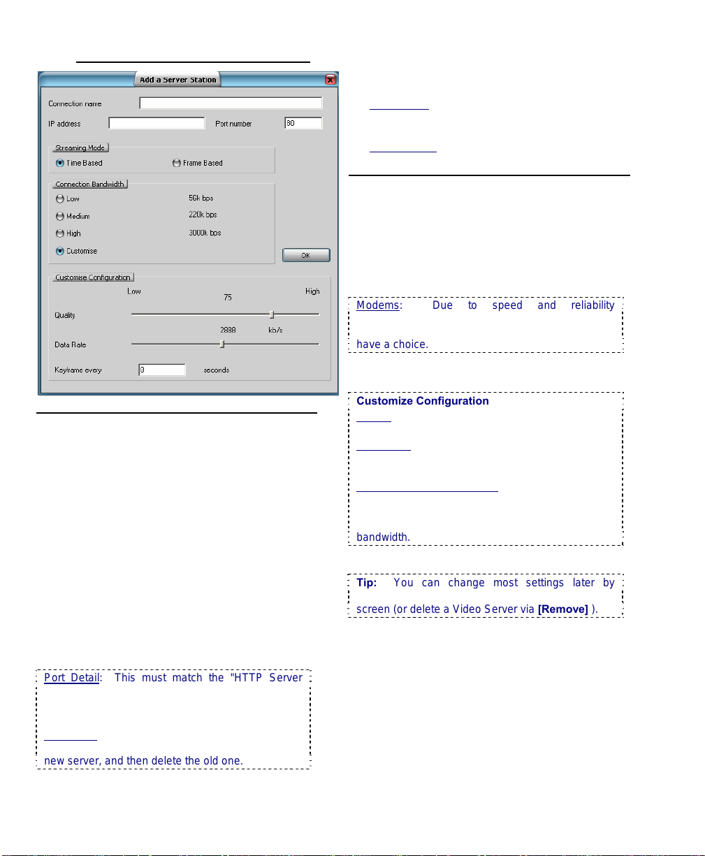
7.10.4
Add (or Modify) a Server Station
Top of the Screen
- [X] (top-right corner): Click this to cancel this
operation, and discard any changes.
- Connection Name: Enter a suitable
name/identifier for this site/server. (This is
'read-only' once set.)
- IP Address: Enter the actual IP address for this
remote server. Format: "###.###.###.###".
- Port Number: Enter the actual IP address for
this server.
- New IP Address: To change an existing IP
address, enter the new one here. Format:
###.###.###.###.
- New Port Number: To change an existing Port
Number, enter the new one here.
Port Detail: This must match the "HTTP Server
Port" for this remote server. Typically "80".
Locator: (At that PC), ÖWindows Control Panel,
ÖDSR Configuration, ÖRemote Service Manager.
Read-Only: The Connection Name cannot be
changed. If you wish to change this, [Add] it as a
new server, and then delete the old one.
- Streaming Mode: This determines how
streaming playback will operate when playing a
remote file.
• Time Based: File playback duration maintained
(regardless of your connection speed). Individual
frames may be dropped.
• Frame Based: Every frame will be shown no matter
how long it takes.
Middle of the Screen
- Connection Bandwidth: This sets the
streaming playback image quality and frame rate
as suitable for your type of connection. Indicate
your connection speed (Low for dial-up; Medium
for cable/DSL; High for a network (LAN)
connection).
Modems: Due to speed and reliability
considerations, dial-up connections are NOT
recommended. Use a faster connection if you
have a choice.
- (•) Customize: This expands the bottom of the
screen to access custom bandwidth parameters
Customize Configuration
Quality: Sets the relative amount of video detail to
be included in non-key frames;
Data Rate: This sets the maximum video data
transmission rate to be used by the connections
with this specific NetVision video server;
Keyframe every (x) seconds: This determines how
often a complete frame is sent compared to only
changes from the previous frame. Lower values
provide better image quality and require more
bandwidth.
- [OK]: Select this to save your settings.
Tip: You can change most settings later by
selecting [Modify] in the Server Management
screen (or delete a Video Server via [Remove] ).
36 NetVision Plus/Elite and Micro DVR v2.3 SP2 User's Guide 21-0400E v2.3.3
Page 45

8
Viewing Live Cameras
8.1
Viewing Cameras
from a Remote Station
From a remote surveillance station, you can
view up to 16 cameras at the same time.
These can be all from the same Video Server,
or in different locations.
Also See:
8.4 Monitoring Cameras via TV (Spot Monitor)
29 Viewing Cameras through a Web Browser
TechTip: For multiple Video Servers set for
specific users, the Video Servers must all be set up
with the same user name and password for you
(entered when you start the remote software).
Alternatively, you can exit and restart the remote
station software if you need to enter a different login
name and password.
Custom_Titles: Each camera-view can include up to
three custom titles (that are set up at the Video
Server.)
Audio: Audio: Some cameras at each Video
Server can have a microphone connected. This
sound can also be monitored at authorized remote
stations.
Related Topics: 16.7 Remote Audio Monitoring
Connection vs. Performance: Good performance
for remote viewing and playback greatly depends on
your connection to the internet and/or Video Server.
Dial-up connections provide poorer performance.
8.1.1
Connecting to a Video Server
Double-click a Video Server in the list
near the upper-right corner of your
display (or select a station and click
the 'Connect /
Refresh' button). Then, watch for a success
message in the 'Status List'.
small scroll bar at the bottom to view longer messages)
Tip: If your desired Video Server is not in the list,
refer to: Related Topics: 13.3 Station List
(Identifying the Video Servers)
TechTips: For a Video Server to be available, its
software must be running (although no one needs to
be logged in there).
If the connection fails due to an incorrect user name
or password, you can shut down and restart the
remote station software, and login as the correct
user. You may also need to contact the Video
Server to ensure your name and password are set
up.
(You can use the
Once a successful connection is made,
camera listings will show all cameras that you
have the permission to view.
.
21-0400E v2.3.3
Welcome
Common
Admin Config Install Tech-Ref
37
Page 46

8.1.2
Viewing Cameras
After connecting, you can:
• Select NTSC or PAL (top-right corner);
• Select the display mode for your desired
number of cameras (1, 4, 9, or 16);
SVGA: With 800x600 screen resolution (SVGA), you
can view 1, 4, or 9 cameras at a time. If you select
16 camera mode, you will be asked to switch to 1024
x 768 if needed.
(QuickRef
ÖProperties, ÖSettings, Ö1024x768, Ö[OK] ).
: Right-click Windows desktop,
• View a specific camera: Double-
click a desired camera in the Video
Server list
(or select a camera, and click
'OnLine View');
the camera list, click the [+] to view the list.
If the Camera-View Is Not Displayed: The
username and/or password that you entered during
login may not be registered at the Video Server.
(You can also try shutting the software down and
logging in again.)
Multi-Camera View: If all camera windows are
already being used, select the desired window
(small green button, top left) before double-clicking
the camera.
Blue: A blue camera icon indicates a camera that is
already selected in one of the four camera windows.
Buttons in Top Right Corner of Camera View:
These allow removing/stopping a camera-view [X],
starting or stopping recording, adjusting a PTZ
camera, or accessing additional PTZ controls. (see
"Related Topics").
8.1.3
Disconnecting
Tip: If a [+] appears instead of
To quit viewing a single camera, click the [X]
near the top right corner of the camera-view.
To quit viewing a Video Server,
select the Video Server, and then
click the "Disconnect" button near
the top-right corner of the main
screen.
Related Topics:
8.3 Changing a Camera's View (Pan/Tilt/Zoom);
9 Recording Camera-Views;
8.2
Viewing Cameras at a Video Server
At a Video Server, you can:
• Select a display mode (1-16 cameras) using
the buttons near the top right corner of the
screen.
Tip: Try the different display modes to see which
ones you like. For maximum frame-rate, be sure to
display no more than one camera from each
capture board at the same time.
• Select (and deselect) cameras to view (use
the buttons under "Display", top-right)
• Set the display to step through
cameras sequentially;
• Double-click a camera to view it full-screen
(and double-click the large image to return to
the previous view).
Note: If instant-recording is enabled, double-
clicking starts a recording as well. (To stop
recording, click the camera button in the "Recorder"
area on the right.)
Operator vs. Supervisor: Local users with
‘Operator’-level login may be limited to specific
cameras.
Details: 11.1 Video Server Users and Passwords
Tips: A green camera number (in the camera
display area) indicates a selected camera; To view
the camera number for a specific image, hover the
mouse over the camera-image and wait 1-2
seconds (do not click the image).
Custom_Titles: Each camera-view can include up to
three custom titles.
Related Topics: 16.1 Set up Cameras and Titles
Microphone: Some cameras at each Video Server
can have a microphone connected. Related Topics:
16.5 Enable Audio for Specific Cameras
Oval Panoramic Camera Images (v2.3 SP2): The
PVS option (panoramic video surveillance) allows
you to digitally manipulate panoramic camera
images. The PVS control is documented
separately.
Related Topic: 31 Panoramic Video Surveillance
(PVS)
Auto Alarm Display (v2.3 SP2): Cameras can be
set to display automatically when motion is
detected, or an external alarm occurs.
.
38 NetVision Plus/Elite and Micro DVR v2.3 SP2 User's Guide 21-0400E v2.3.3
Page 47

Related Topic: 15.3 Auto Alarm Display (v2.3
SP2)
Alarm Overlay (v2.3 SP2): Special camera subtitles
can be set up to appear for individual cameras
when motion is detected, or an external alarm
occurs.
Related Topic: 15.4 Set Up Alarm Overlays (v2.3
SP2)
Multi-Camera Views: In general, camera
numbers are associated with a specific screen
area. In view-modes that do not show all
cameras at once, only the cameras associated
with different
screen areas can be viewed at
the same time.
Screen Area Þ Camera #s by Screen Area
NetVision Model Ø 1 2 3 4
Plus/Elite: 16 cameras 1-4 5-8 9-12 13-16
Plus/Elite: 8 cameras 1-2 3-4 5-6 7-8
Plus: 4 cameras 1 2 3 4
The indicated cameras will be displayed in sequence in
their respective screen 'quadrant'. E.g., 1, 5, 9, & 13,
then 2, 6, 10, & 14, etc.
On-Screen 'Quadrants':
1 2
3 4
Related Topics
8.3 Changing a Camera's View (Pan/Tilt/Zoom);
9 Recording Camera-Views;
17.2.5 Misc. (see "Instant Recording")
Also See
8.4 Monitoring Cameras via TV (Spot Monitor)
29 Viewing Cameras through a Web Browser
:
:
Tip: When showing only 4
cameras, the 8 camera
desktop allows toggling
between odd and even
cameras.
21-0400E v2.3.3
Welcome
Common
Admin Config Install Tech-Ref
39
Page 48

8.3
Changing a Camera's View (Pan/Tilt/Zoom)
8.3.1
Introduction
For cameras that support PTZ control, you can
zoom in or out, and 'aim' the camera as
desired. This can be done at the Video
Server, or remotely.
PTZ Permissions: Only one person can control a
specific PTZ camera (port) at a time. Remote
access to PTZ cameras is based on remote user
permissions set up at the Video Server. Any
remote PTZ user can be bumped/blocked by an
operator at the Video Server, or another remote
user assigned a higher PTZ priority.
A maximum idle time can be set for Video Server
users to ensure this feature is not blocked
unnecessarily. Similarly, remote users may be set
with a time limit for PTZ sessions.
PTZ Control after Start-Up: The PTZ server has a
delayed start-up to allow Windows services to
stabilize. (The PTZ feature will not be available
until 1 minute (approx.) after the Video Server is restarted.)
8.3.2
PTZ Control from a
Remote Station
Connect to the Video Server and open/view
the desired camera.
Related Topics
a Remote Station
Then, click the PTZ icon in the top-right corner
of the camera image.
(Remote Module software): Click the PTZ icon.
Then, enter the Video Server IP address and a valid
remote user name, and click [OK]. Note: The
remote module uses the same PTZ control as a
Video Server (to follow/below).
PTZ Not Available: This may mean that someone
with higher PTZ priority is presently controlling the
camera.
Tip: The PTZ speed control and other
advanced PTZ features are available through
the "More PTZ Function" (folder) button (after
you click the PTZ button). Note: For cameras
connected through a switcher, you'll need to click the
folder icon, and set the [Monitor] value first (switcher
port associated with this camera).
: 8.1 Viewing Cameras from
To 'aim' the camera, 'hover' your mouse
around the camera-view, and watch for the
cursor to change to an arrow or magnifying
glass. Then, click-and-hold the image with the
cursor showing the desired action. To zoom
in, click the centre (magnifying glass). To
zoom out, right
glass).
To set the panning speed, see "Other PTZ Features",
to follow.
When finished, click the PTZ symbol again.
-click the centre (magnifying
Related Topics:
16.3 Pan/Tilt/Zoom Activation and Set Up
40 NetVision Plus/Elite and Micro DVR v2.3 SP2 User's Guide 21-0400E v2.3.3
Page 49
8.3.3
PTZ Control at a Video Server
After logging in, click the PTZ button
near the bottom-right corner of the
main desktop (a narrow form will
appear on the right). Then, select the camera
number (beneath "model"), and click
[Connect].
Exception: For cameras connected through a
switcher, you'll need to set the [Monitor] value first
(switcher port associated with this camera).
To 'aim' the camera, use the
arrow buttons (click-click-click,
or click-and-hold). To zoom in,
or out, use the arrows marked
"Zoom" (click-and-hold).
Tip: You can also zoom in using
the magnifying glass.
To set the panning speed, see
"Other PTZ Features", to follow.
To close the PTZ control screen when finished,
right-click the PTZ icon in the top-left corner
(or any blank area) of the form, and select
Exit.
8.3.4
Other PTZ Features
On a remote station, these selections are
provided through a separate 'folder' button
(available when already using the PTZ feature).
To close the screen, click the [X].
Pre-Set Positions: This feature alone may
make you a believer in the value of PTZ
cameras: You can store 20 pan/tilt/zoom
positions and quickly recall them later. This
allows one camera to 'pretend' it's 20 cameras.
To Save a PTZ 'Pre-Set': Set the camera
position as desired, select an available 'preposition' number, and click [Set].
Tip: Store the most common/useful ones in the first
4 positions (available through buttons 1-4
thereafter). To check if a pre-set is available, see
the next topic.
Remote Station ×
Video Server
Ö
To Show a Pre-Set PTZ Position: The first
four positions are available by clicking [1], [2],
[3], or [4]. For any pre-set position (1-20),
select (or enter) the position number, and click
[Show].
[Clear Preset]: (If present). Clears all defined
preset positions at once.
Iris
(Close/Open, or Arrows): Allows manually
brightening or darkening the camera image
(iris).
(Near/Far, or Arrows): Allows manually
Focus
adjusting the focus for objects that are closer
vs. farther away.
Tip: This is useful where the camera view is
partially blocked by a nearer object in the frame.
PTZ Speed (Slider Bar): This allows
increasing or reducing the panning speed.
21-0400E v2.3.3
Welcome
Common
Admin Config Install Tech-Ref
41
Page 50

Monitor: Pertains to cameras connected
through a switcher. This is the camera ID/port
on the switcher (receiver-driver ID).
AutoFunct: Allows selecting auxiliary
functions that were previously set up (if
available/supported).
AutoPan: Sets the camera for automatic
panning (if available/supported).
AutoFocus: This returns the focus control to
automatic (if available/supported).
Tip: Selecting a pre-set position will also put the
camera into auto-focus mode.
AutoIris: When pressed, the camera will
automatically adjust to changes in brightness
(if available/supported). When not pressed,
the manual brightness (iris) control is in effect.
Tip: Selecting a pre-set position will also put the
camera into auto-iris mode.
Menu: Activates the on-screen menu (for
cameras that support this).
Exception (Pelco-P): For a Pelco-P camera, select
preposition 95 to enable the on-screen menu. To
navigate the menus, use pan up/down and iris
open/close.
42 NetVision Plus/Elite and Micro DVR v2.3 SP2 User's Guide 21-0400E v2.3.3
Page 51

8.4
Monitoring Cameras via TV (Spot Monitor)
8.4.1
Introduction
Current video cards include a composite-video
output allowing individual cameras to be
displayed on television monitor(s) manually, in
sequence, or when an alarm occurs (external
input or video motion-detection).
8.4.2
Opening or Closing the TVMonitor Control
To open or close the TV-monitor control,
double-click the television/monitor icon on
your NetVision desktop.
If the TV Control is not Visible: This feature can be
turned on and off.
Related Topics: 14.2 Miscellaneous Settings
8.4.3
Things You Can Do
• Select a camera manually: Click its
associated button in the top portion of the
TV-monitor control;
• Loop through cameras in Sequence:
Click [>>>] to show additional controls,
ensure the cameras to appear in sequence
are selected (bottom portion of the monitor
control), and set the dwell time as desired
(display time for each camera). Then, click
[SEQ.] to start or stop sequential viewing.
• Set Alarms to Trigger Camera Monitoring:
To have camera(s) displayed whenever an
alarm occurs (external input or video motiondetection), click [>>>] to open the bottom of
the TV-monitor control, and ensure “Enable
Alarm Alert” is selected.
Note: Although not specifically related to the “Alarm
Alerts” feature, this feature does require external
inputs to be enabled and/or video motion-detection to
be set up (see “Related Topics”).
• Clear an Alarm: For alarm-triggered
cameras, the camera button will turn red, a
[Reset Alarm] button will appear at the top of
the TV-monitor control, and the camera will
display until acknowledged by an operator.
To clear/acknowledge an alarm-triggered
camera, simply click [Reset Alarm] (while
the specific camera image is being
displayed).
Note: After clearing an alarm, a camera cannot be
tripped again until any alarm-triggered recording is
completed.
Related (and similar) Topics:
18.3 External Sensors and Recording Duration
18.5 Setting up Video Motion-Detection
25.1 Capture Board Reference
6.2 Responding to Alarm Alerts
15.1 Enable/Disable Alarm Alerts or E-Mail
21-0400E v2.3.3
Welcome
Common
Admin Config Install Tech-Ref
43
Page 52

9
Recording Camera-Views
In addition to scheduled and alarm-triggered
recording at a Video Server, manual (instant)
recording can be done at a Video Server (up
to 16 cameras at a time--depending on your
Video Server model), and at remote stations
(up to 16 cameras from any desired Video
Servers at a time).
Instant Playback: If the "Instant Playback" feature is
enabled, videos that are presently being recorded
can be played back. Note: This closes the present
recording file (to allow it to be played-back), and
starts a new recording file.
TechNote: Multi-camera recording at a Video
Server may cause a reduced frame rate. For
maximum frame-rate, be sure to display no more
than one camera from each capture board at the
same time.
Filename / Location Reference:
Captured video files are stored under \dsr-video on
the specific PC, in folders for each 'server' (PC name
or IP address), camera name, and date.
Remote Station: d:\dsr-video\Image\ServerIP
\Camera\date
Video Server: d:\dsr-video\Image\Server
\Camera\date (on each applicable drive).
9.1
Recording at a
Remote Station
Connect to the Video Server and open/view
the desired camera.
Related Topics:
8.1 Viewing Cameras from a Remote Station
Then, use the red button near the top right
corner of the camera-image to start or stop the
recording. (The button will appear yellow
during the recording.)
Recording from a remote station is subject to your
connection speed. Dial-up is slowest.
Alarm Alert Recordings: At applicable remote
stations, the alarm alert feature can be set to
automatically record (and/or only display) the
associated camera/view each time an alarm alert is
received.
Related Topics
13.2 Setting up the Alarm Alert Receiver
:
Tip: You can set the drive(s) for recording.
Related Topics:
13.1 Remote Stations: Basic Set-up
17.2.1 Drive Usage
Audio: Some cameras at each Video Server can have
a microphone connected. This sound can also be
monitored at authorized remote stations.
Related Topics: 16.7 Remote Audio Monitoring
Audio Recording: Audio is not recorded as a separate
file. Instead, it is included in any local or remotely
recorded AVI (or MPEG) files for the specific camera.
Legal Notice: The recording of live audio is subject to
local bylaws. Be sure to find out if audio recording is
restricted in your area before proceeding.
44 NetVision Plus/Elite and Micro DVR v2.3 SP2 User's Guide 21-0400E v2.3.3
Page 53

9.2
Recording at a Video Server
At a Video Server, you can:
• Double-click a camera-image to zoom to full
screen, and start recording (if "Instant
Recording" is enabled);
• Start or stop recording by selecting camera
numbers(s) in the "Record" area of the main
screen (on the right);
• Click [ Record All ] to start or stop recording
all cameras at the same time.
Tip: The camera number appears in yellow for any
cameras that you select for manual/instant
recording.
Recording Priority: Manual (instant) recording will
override scheduled recording on the specific
camera. (Scheduled recording resumes when you
stop instant recording.) Conversely, instant
recording is not available while alarm recording or
pre-alarm recording is in effect for a specific camera
(and alarm recording will override all other types of
recording).
Exception: Beginning with v2.2, you can change
the recording priority if desired.
Related Topics: "Priority" tab under:
17.2 Recording Setup (in DSR Configuration).
Hard Drive Usage Bar: Check the bottom of the
Video Server screen for a hard drive usage
indication. If the coloured bar is 2/3 of the way
across or more, use the 'housekeeping' feature to
free up disk space by deleting or moving files.
Mapped Drives: Recording to a mapped drive is
subject to network speed/loading.
Related Topics
6.4 Alarm / Recording Status Indications at a Video
Server (Camera Number Colours)
10.3 Introduction to Video File Management
(Filekeeping and Housekeeping)
13 Remote Station Configuration
17.2.1 Drive Usage
18 Scheduled and/or Alarm-Triggered Recording
:
21-0400E v2.3.3
Welcome
Common
Admin Config Install Tech-Ref
45
Page 54

#
46 NetVision Plus/Elite and Micro DVR v2.3 SP2 User's Guide 21-0400E v2.3.3
Page 55

System Administration and Maintenance
21-0400E v2.3.3
Welcome Common
Admin
Config Install Tech-Ref
47
Page 56

10
Tasks Applicable to Remote Stations and the Video Server
10.1
PC Date and Time
Especially for the Video Server, it is important
to ensure that the date and time are always
correct--since this information is used to
manage video recordings. There is normally
no reason for this to vary, but it's still best to
check it on a regular basis.
Tips: The time is displayed on the right-hand end
of the Windows task bar. To view the date, 'hover'
the mouse pointer over the time. For details on
setting the date or time, open the Windows on-line
help (e.g., from the Windows Control Panel), and
search for "Date".
10.2
Checking your Software Version
10.2.1
Video Server Software
Locator: (Logged in at the Video Server as
a "Supervisor"). Select: [Utility], then
[System Information].
When finished, click [OK], and then
[Close] the utility menu.
10.2.2
Explore, browse, or search for
RemoteStation.exe. Then, right
and select Properties (look in Version
Tip: From a link (shortcut) to the Remote Station
software, you can right-click the shortcut, select
Properties, and then [Find Target]. Then, rightclick the file, and select Properties.
To quickly locate a program file from its
shortcut: Right-click the shortcut, select
Properties, and select [Find Target]. (Now you
can right-click the file itself and select Properties.)
Remote Station Software
-click the file,
).
10.3
Introduction to Video File
Management (Filekeeping
and Housekeeping)
10.3.1
Introduction
As video files can be ultimately consume a
large amount of hard-drive space, it is
important to work with your files on a regular
basis.
Why? To ensure:
• Space is always available for recording
• Files of specific interest are always retained
Attention: Deleted files cannot be recovered. It is
best to check your backups before deleting any
files.
You can:
• Manage files using the new Filekeeping
function.
• Local (and downloaded) Files: Copy, Backup,
Delete, (Add a Remark), or Download desired files.
• Remote Files: Download (and/or Preview) files.
Tip: Files can be also be previewed in the file list or
viewed in playback. (Filekeeping functions are
accessible through Playback and the file lists.)
• Manage files using the Housekeeping
function
• Remote Station: Backup and/or delete files that
were recorded or have been backup up onto that
remote PC.
• Video Server: Backup and/or delete local files, or
'remote' files -- for folders that have been 'mapped
to' as a drive letter.
Tip: Includes a small built-in playback window.
• Set the system to delete older files every day
at a certain time (Self-housekeeping).
Related Topic: 10.7 Automatic Video File
Management (Self Housekeeping)
• Manage files outside of the NetVision
software.
48 NetVision Plus/Elite and Micro DVR v2.3 SP2 User's Guide 21-0400E v2.3.3
Page 57

10.3.2
Filename / Location Reference:
Captured video files are stored under \dsrvideo on the specific PC, in folders for each
'server' (PC name or IP address), camera
name, and date.
Video Files: Remote Station: d:\dsr-video\Image\
ServerIP\Camera\date, where "d" is the drive
selected under: Utility (tools symbol), ÖRecording
Drive Setup.
Video Files: Video Server:
d:\dsr-video\Image\ Server\Camera\date.
(The drive(s) are selected under: Windows Control
Panel, ÖDSR Configuration, ÖRecording Setup).
Downloaded Files:
d:\Dsr-Video\Remote\server\Camera\Date, where
"d" is the drive that contains the operating system
(typically "C:").
Backup Files: d:\dsr-
Backup\Image\Server\Camera\date. (The drive is
selected during Filekeeping / Housekeeping.)
Tip: The first letter of the filename indicates the
type of recording: Alarm-triggered, Pre-alarm,
Scheduled, or Manual Recording.
File Type Tip: Videos are recorded as standard
"AVI" files that can be played back using NetVision,
or any typical Windows media player program.
10.3.3
Technical Details
Files: You can work with local files (recorded on that
PC, or downloaded), or via folders that have been
'mapped to' as a drive letter. After searching for
'Remote' files, only "Preview" and "Download" functions
will be available in the file list. After downloading, the
other functions will be available.
CDs and Portable Drives
CD/DVD burner, you can backup files onto CDs/DVDs
once they have been 'formatted' to be accessible
through a drive-letter (e.g., using DirectCD). Similarly,
portable drives can be used as long as they are
available to the PC before you select "Backup".
Backing up while Recording: If possible, it is best to do
your housekeeping when the system is idle, since
backing up files while recording is in progress (on the
same hard drive) can be very slow.
Hard Drive Usage Bar: Check the bottom of the Video
Server screen for a hard drive usage indication. If the
coloured bar is 2/3 of the way across or more, it's time
to do some file management.
: If your PC includes a
Especially for the Video Server, it is important
to ensure that the date and time are always
correct--since this information is used to
manage video recordings. There is normally
no reason for this to vary, but it's still best to
check it on a regular basis.
Tips: The time is displayed on the right-hand end
of the Windows task bar. To view the date, 'hover'
the mouse pointer over the time. For details on
setting the date or time, open the Windows on-line
help (e.g., from the Windows Control Panel), and
search for "Date".
10.4
To Allow Using a Blank CD
(Roxio - Easy CD Creator 5
basic
with DirectCD)
If your PC includes a CD burner (typically
included with Video Servers), you must 'format'
CDs to make them accessible to the
housekeeping feature.
:
Steps
1) Open the CD burner drive, and insert
a new/unformatted CD.
2) Close the drive tray, and wait a few
moments for the Easy CD 'project'
screen to appear.
For a CD that has Already been formatted: After a
few moments, you will see a "CD Ready"
message. (Skip the rest of these steps.)
Alternative
software manually (e.g., [Start], ÖPrograms,
ÖRoxio Easy CD Creator 5, ÖProject Selector.
Shortcut Tip
desktop or 'quick launch' bar, browse (or search)
for the following file, and "Ctrl
desired location: C:\Program Files\Common
Files\Adaptec Shared\CreateCD
\CreateCD50.exe.
: You can also launch the 'burner'
: To create a 'shortcut' on your
-Shift-Drag" it to the
3) ("Easy CD Creator 5basic - Select a Project"):
'Hover' your mouse cursor over "Make
a Data CD", and then click [DirectCD]
in the choices that appear.
("DirectCD format utility"): Select the CD
4)
drive if needed, and click [format CD].
If this Button is not Available: This means you
forgot to insert a CD, the CD is already formatted,
or the CD cannot be formatted by this software.
21-0400E v2.3.3
Welcome Common
Admin
Config Install Tech-Ref
49
Page 58

5) ("DirectCD"): Enter a disk label if
desired, and click [Start Format].
Tip: Disk labels identify the CD when browsing for
drives in Windows Explorer.
6) Wait for a "CD Ready" screen to
appear. (Your CD will now be
available to the housekeeping
feature.)
--------------------------------------------------
7) After copying files / When you try to
eject the CD: For a newly formatted
CD (or after copying files), you will be
prompted with some choices when
you try to eject the CD. If you want
the disk to be readable by other PCs,
be sure to select "Close to Read on
Any PC...".
Tip: DirectCD will typically re-enable the CD the
next time you insert it into the CD 'burner' drive (if
not, you will need to repeat steps 1-6 if you need
to place more files on the CD).
Warning
: Choosing to protect the CD so it cannot
be written to again is a permanent operation that
will turn the CD into a 'read-only' CD-ROM.
10.5
10.5.1
Introduction to Filekeeping
Filekeeping (v2.3 SP2)
Filekeeping provides a convenient way to
manage video files. Filekeeping provides new
functionality including:
• Copying files to any desired location
• Adding and viewing remarks
• Accessibility directly from the file list (after
searching for video files).
Note: Filekeeping applies to the current/last
search-results file-list. Marks applied within
previous search results can be processed by
performing a new search that covers the
collective/overall time frame. Marks will be
removed from files once they have been processed
through Filekeeping.
10.5.2
Filekeeping Steps
1) Perform a search for videos from a
desired server, camera, and date/time
range.
Sync Playback (server/local files only):
•
• Select: [Playback], Ö[Sync Playback].
The SyncSearch screen will open.
• Select a date, and the desired type of
recordings, and click [Search / Play]. The
SyncPlayback screen will open.
• If a video starts playing automatically, click
"Stop" (black square), and then go into the
File List (page/magnifier).
Related Topics
7.3 Synchronized Playback (v2.3 SP2)
7.8 Working with the File List (v2.3 SP2)
:
• Video Search (or optional 360 Playback):
• Select: [Playback], Ö[Video Search]
(or [360 Playback] ). The Search screen will
open.
Remote Software
button, then select [Video Search] (or [360
Playback] ).
• Select all criteria, and click [Start Search].
The number of 'found' files will appear.
• If desired, perform a Motion Search:
Click [Motion Search], select 'detection
zones' and other criteria, and click [OK].
50 NetVision Plus/Elite and Micro DVR v2.3 SP2 User's Guide 21-0400E v2.3.3
: Click the coloured 'Play'
Page 59

When it finishes, the number of 'motion-found'
files will appear.
• Select [File List] beside "Search" or "Motion
Search" as applicable/desired.
Related Topics
7.6 Working with the Playback Screen (v2.3
SP2); 7.8 Working with the File List (v2.3 SP2)
: 7.4 Video Search (v2.3 SP2);
2) In the file list, use the right-click menu to
preview files, and 'mark' them for each
desired Filekeeping action.
Mark For: Copy, Backup, Delete, (Add/view
emark), Download (remote files).
R
Tip: You can select multiple files using Shift+Click
(block of files), or Ctrl+Click (random files).
Block of Files
the 'Shift' key, 3) Select last file, 4) Release the
'Shift' key.
Remote Files: After searching for 'Remote' files,
only "Preview" and "Download" functions will be
available in the file list. After downloading, the
other functions will be available.
: 1) Select 1st file, 2) Press & hold
3) Click [X] (top-right) to close this screen
and access the playback screen.
4) Go into the Filekeeping function (broom
icon), to process your 'marked' files.
When you click [Start FileKeeping],
your marked files will be processed.
10.5.3
Note: Wait briefly while this screen initializes. This
screen will remain 'greyed out' if no files have been
'marked' for FileKeeping functions.
Note: Filekeeping applies to the current/last
search-results file-list. Marks applied within
previous search results can be processed by
performing a new search that covers the
collective/overall time frame. Marks will be
removed from files once they have been processed
here.
The Filekeeping Screen
21-0400E v2.3.3
Welcome Common
Admin
Top of the Screen
- [View/Edit Current File List]: This opens the
current file list and allows applying (or removing)
'marks' for the various Filekeeping tasks.
Right-click Menu: Preview, (Mark For): Copy,
ackup, Delete, (Add/view Remark), Download
B
(remote files).
Related Topic
7.8 Working with the File List (v2.3 SP2)
- [X]: Select this to close this screen (same as
clicking [Close] at the bottom).
Config Install Tech-Ref
:
51
Page 60

Copy
- This shows the number of files marked to be
copied, and the amount of space they will take
up.
- Path: Enter (or '[Browse] to') where you wish
the file copies to be placed.
Note: This uses NetVision's standard folder
structure
under the selected location. (Creates the structure:
"dsr-video\image\Server\Camera\Date").
d:\ (root): Selecting the root of a drive is a good
idea for removable media. Files will be available to
search and playback. Note: Will cause duplicates
when searching if used with another permanent (or
available) local drive. To avoid this, use 'backup'
instead, other media, or a subfolder.
Any subfolder: Will only be accessible outside of
NetVision (Windows explorer, media players, etc.).
Middle of the Screen
Backup
Note: Because of their location, 'motion-found' files
cannot be backed up (only copied).
Related Topics:
7.5 Searching for Motion (v2.3 SP2)
- This shows the number of files marked to be
backed up, and the amount of space they are
taking up.
- Path: Select the desired backup folder.
Note: This will show all local drives. The following
folder structure will be created: d:\dsrbackup\image\Server \Camera\Date" (where "d" is
the selected drive letter). These files will be
available for searching and playback when you
select "Backup" (Local) type of files.
- Delete after Backup: Selecting this will cause
all files "marked to be backup up" to be deleted
after the backup is completed.
Delete
- This shows the number of files marked to be
deleted, and the amount of space this will free
up.
Download
- This shows the number of remote files marked
to be downloaded, and the amount of space
they will take up.
Note: Files are downloaded to d:\Dsr-
Video\Remote \server\camera\Date, where "d" is the
drive that contains the operating system (typically
"C:"). Thereafter, these files will be available for
searching and playback when you select "Normal"
(Local) type of files.
Bottom of the Screen
- [Start FileKeeping]: Select this to process all
marked files using the shown file locations.
- [Stop FileKeeping]: Select this if you want to
stop a FileKeeping process that is already
underway.
- [Close]: Select this to close this screen (same
as clicking the [X] in the top-right corner).
52 NetVision Plus/Elite and Micro DVR v2.3 SP2 User's Guide 21-0400E v2.3.3
Page 61

10.6
Housekeeping
10.6.1
Access the
housekeeping feature:
At a Remote Station: Click the
Housekeeping symbol (broom)
near the bottom right corner.
At a Video Server: (Logged in at
the Video Server), Select: [Utility],
then [Housekeeping].
--------------------------------------------------
Then, select Backup or Delete
depending on what you wish to do.
Refer to the descriptions that follow
while working in the housekeeping
screen.
To Exit from this Screen: Click [Cancel] near the
bottom-right.
10.6.2
View a List of Video/Alarm Files
(select server, camera, date)
Select the following items to view a list of
associated alarm/video files:
Server
Select the 'server' (PC name or IP) that has the
video files.
To include files on other PCs ('mapped' drives),
ensure "mapped" is selected (under "From").
Camera
Select a desired camera, or [All].
Date
Select a specific date, or [All].
[Refresh]: Click this (bottom of the screen) to
update the list for new recordings (per selected
parameters).
10.6.3
Working with Video Files
The main part of the screen shows a list of
video files. You can sort by clicking any
column heading, and move around using your
mouse wheel, or the scroll bars.
Select the types of recordings to be included in
the list (alarm, instant, 'pre-alarm', and/or
schedule):
File-Type Reference: The first letter of the
filename, and the "Event" column show the
type of recording:
A / ALM: A motion / alarm-triggered
recording;
P / PRE: A pre-alarm recording
(immediately before motion was detected);
R / REC: A manual / instant recording;
S / SCH: A scheduled recording.
To select (or deselect) a file, click the
associated camera name in the 1
Tip: Select the camera name, not the check-box.
st
column.
21-0400E v2.3.3
Welcome Common
Admin
Config Install Tech-Ref
53
Page 62

Select All / Delete Original...
(Bottom-Left Corner)
• Select All Files
: Selects (or deselects) all
files in the list;
• Delete original file(s) after backup
: If
selected (9), the files are effectively moved
to the new location. If not selected, the files
are copied to the new location.
To view a file first (i.e., before backup or
deletion), select the file (click the camera
name), and click [PlayBack] (in the row of
buttons at the bottom).
Before backing up file(s), select the desired
target drive letter near the top-right corner of
the screen.
Mapped (Video Server PC Only): This includes
'mapped' drives from other PCs in the list.
Note: Moved files will be placed under d:\dsrvideo\Image\Server(orIP)\Camera\Date
To backup or delete your selected file(s), click
[Start] at the bottom of the screen. When
prompted to confirm, respond as desired (OK
or Cancel).
Minimize: You can use the [Minimize] button to
hide the housekeeping window for lengthy file
management operations (such as when moving a
large number of files through a slow network
connection). To restore the housekeeping screen,
click [House keeping] on the windows taskbar, and
then click the yellow broom symbol in the top-left
corner of the screen.
--------------------------------------------------
When finished, click [Cancel] to close the
'housekeeping' screen.
10.7
Automatic Video File Management (Self Housekeeping)
You can set the NetVision Video Server and
remote stations to perform file management
tasks automatically on a recurring schedule.
Each scheduled task is saved as a ‘Plan’,
allowing different file management tasks to be
performed for different servers on different
days or times, etc.
Also See: 10.3 Introduction to Video File
Management (Filekeeping and Housekeeping)
10.5 Filekeeping (v2.3 SP2); 10.6 Housekeeping
Locator: At the Video Server PC (will
prompt for "Supervisor" login),
Select: (Windows task bar) Start, Settings,
Control Panel, DSR Configuration.
Desktop Link: There should also be a link to this on
your desktop called "NetVision Configuration".
Tips: If you cannot access the Windows task bar,
press Ctrl-Esc (or your 'Windows' key). To view the
names for items on the task bar, click a blank area on
the bar, and then 'hover' your mouse pointer over each
item.
Logon as a "Supervisor" when prompted.
Then, double-click Self-Housekeeping Setup
in the list. When the screen appears, make
your desired selection(s).
Remote Station: (Logged in at a remote
station), Select: The "Utility" button
(tools symbol), Ö Self-Housekeeping
Setup, Ö[Start Setup].
54 NetVision Plus/Elite and Micro DVR v2.3 SP2 User's Guide 21-0400E v2.3.3
Page 63

Top of the Screen
This area shows a list of defined ‘plans’
(scheduled housekeeping tasks), and allows
you to [Add] new ones, [Remove] existing
ones, [Save] your changes, etc.
[Buttons] on the right: To set up a new
‘plan’, click [Add], type a suitable name, and
click [OK]. To view settings for an existing
one, select the ‘plan’ name in the list, and then
observe setting on the rest of the screen.
[Edit] allows changing settings for a selected
‘plan’, while [Remove] will delete a selected
one from the list.
Attention: Always use the [Save] button to retain your
added ‘plans’ and related settings, since clicking [OK]
only closes the screen without saving anything.
Details
Action: The file management task to occur on
the scheduled days/times.
Suspend: This blocks this ‘plan’ from executing
without having to delete it. For temporary use.
Retain: Retains only the specified number of days of
files in the "DSR-video" folder, and deletes all older
files.
Attention
conjunction with manual file-management (NOT
Self-Housekeeping). You must be sure to copy or
move any alarm/video files that you wish to keep.
Details: 10.3 Introduction to Video File
Management (Filekeeping and Housekeeping)
10.5 Filekeeping (v2.3 SP2); 10.6 Housekeeping
Backup: Copies older video files to the specified target
location, while leaving them in the original "DSR-video"
folder.
Move: Moves older video files to the specified target
location, while deleting them from the original "DSRvideo" folder.
Synchronize Backup: Copies older video files that do
not already exist in the specified target location
(compared by date), while leaving them in the original
"DSR-video" folder.
: This selection should be used only in
Synchronize Move: Moves older video files that do
not already exist in the specified target location
(compared by date), while deleting them from the
original "DSR-video" folder.
( ) days of files: This determines the 'age' of
files that will not be affected by the scheduled
housekeeping task/plan. (All older files in the
..\dsr-video\image folder will be copied
and/or deleted at the scheduled time.)
Action Start: Use the up/down arrows to
select how often the scheduled task is to occur
(every day, once per week on a specific
weekday, or once per month). Then, click
within the minutes, hours, or seconds, and use
the up/down arrows to set the time of day for
the process to start.
Note: Plans with the same start time will be executed in
alphabetical order.
Tip
: For dedicated access to the hard drive, select a
time of day when recordings are unlikely to occur.
Files From
Application: Use the up/down arrows to
select a source application here. (“DSR” for
files on your local NetVision video server PC,
“Remote” for files obtained from a remote
server, or “ATM” for files associated with the
optional ATM interface.)
Server Name: Use the up/down arrows to
select the originating server associated with
the files to be deleted or moved, etc.
21-0400E v2.3.3
Welcome Common
Admin
Config Install Tech-Ref
55
Page 64

Drive
(List of drive letters): Select all drives to be
affected by the specific housekeeping
task/plan.
File Type
(List of types of recording files): Select all
types of recording files to be affected by the
specific housekeeping task/plan.
(Bottom of the screen)
Files To: Enter a target backup folder here, or
click […] to browse to (and select) a desired
folder.
Generate Log Files: This causes the selfhousekeeping feature to record the scheduled
file management ‘plans’ that were executed on
each specific day.
Location and Filename: Self-Housekeeping logs can
be found under: d:\dsr-video\Log\HK\yyyymmdd.txt
--------------------------------------------------
When finished, click [OK], and then click
[X] to close the list (upper-right corner).
Attention: All new or changed self-housekeeping tasks
(plans) take effect beginning the next day after
housekeeping settings are saved and the NetVision
software is re-started.
the self-
10.7.1
Viewing the Self-Housekeeping
Logs
The execution of self-housekeeping tasks
(plans) can be set to be recorded in a log file.
This record is stored in a text file (one file per
day).
To view these files in your default text editor
(e.g., notepad), locate and open (double-click)
the indicated file.
File Locator:
d:\DSR-Video\Log\HK\yyyymmdd.txt
("d" represents the drive letter of the recording hard
drive.)
56 NetVision Plus/Elite and Micro DVR v2.3 SP2 User's Guide 21-0400E v2.3.3
Page 65

11
Tasks Performed at the Video Server Only
11.1
Video Server Users and Passwords
Related Topics: 11.2 Remote Users and Permissions
(+ HTTP server port)
11.1.1
Video Server Passwords
Two login names and passwords are initially
provided for logging into the Video Server:
Default Video Server User
Names and Passwords
User name Password (Permissions)
Super -- Access to everything;
Operator -- Everything except
Notes: Supervisors can also shut down the NetVision
software. For operators, this is configurable. These
passwords do NOT pertain to remote stations.
PTZ priority 0
configuration tasks
( [Utility] menu, and
Control Panel ÖDSR
Config.); Can be
limited to specific
cameras (see next
heading); PTZ priority
1
(2nd highest)
Locator: (Logged in at the Video Server as
a "Supervisor"),
Select: [Utility], then [Option Setting].
(highest).
11.1.2
Additional Local Users (Local
User Manager)
You can set up additional local users with their
own password if desired. You can also set
whether each new user will be logging in at the
"Super" level, or as an "Operator" (see the
preceding table for permissions).
To set up local users and passwords, open the
Local User Manager, and then refer to the
descriptions that follow while making your
selections.
Locator: At the Video Server PC (will
prompt for "Supervisor" login),
Select: (Windows task bar) Start, Settings,
Control Panel, DSR Configuration.
Desktop Link: There should also be a link to this on
your desktop called "NetVision Configuration".
Tips: If you cannot access the Windows task bar,
press Ctrl-Esc (or your 'Windows' key). To view the
names for items on the task bar, click a blank area on
the bar, and then 'hover' your mouse pointer over each
item.
Logon as a "Supervisor" when prompted.
Then, double-click Local User Manager in the
list. When the screen appears, make your
desired selection(s).
Select Password , and then enter your
desired password (once under "Password",
and again under "Confirm"). Tip: This helps
to protect against saving an incorrectly typed
password.
When finished, click [OK], and then
[Close] the utility menu.
21-0400E v2.3.3
Welcome Common
Admin
Config Install Tech-Ref
57
Page 66

List of Users (Registered User Name)
This shows a list of the users that can log in
locally, along with the login authority for each
one (Supervisor vs. Operator).
[User Group]
on the right
This helps to maintain PTZ access for remote
users.
Group Name: Select "Supervisor" or
"Operator";
PTZ Server / Idle Time Limit (min.): This
causes any user of the selected type to be
logged out of the PTZ feature if they stop
actively using PTZ control for the duration
entered here (1-9999 minutes, or 0 for "No
Timeout").
Tip: This helps to ensure PTZ control will be available
for remote users. If using this feature, be sure to set
this for both "Supervisor" and "Operator" (click [Apply]
after the first one, and [OK] when finished).
Four Buttons near the Bottom
Except for "Add", these buttons pertain to the
user you have selected in the list.
[Add]: Select this to create a new local user.
Enter the name and password (twice) when
prompted, and click [Next]. You will be
advanced to [Properties] automatically to set
the login level as "Supervisor" or "Operator".
[Remove]: Allows deleting a previously-added
local user. (Select the user, and click here.
When asked to confirm, click [OK].
[Set Password]: This allows changing the
password for a local user. (Select the user,
and click here. Then, enter the new password
(twice) when prompted, and click [OK].
[Properties]: This allows setting permissions
for a previously-added local user (i.e., not the
default users). (Select the user in the list, click
here, and then make your selections.)
Logon As: Allows setting the local user as an
‘Operator’ or ‘Supervisor’ (details previous/above).
Camera Mask
allows limiting the cameras that an ‘Operator’ will be
able to view/control. Select “Camera Mask” (9), and
then select the desired cameras.
--------------------------------------------------
and Grid with Camera Numbers: This
When finished, click [OK], and then click
[X] to close the list (upper-right corner).
Attention: To recognize any DSR Configuration
changes made while the Video Server software is
running, you may need to restart the software.
11.2
Remote Users and Permissions (+ HTTP server port)
Remote access to Video Server services are
password-protected. Each server module can
be set to allow access to:
• A person logged in at a remote station using
any name and password (but they cannot be
left blank), or;
• Specific users/passwords and permissions
as defined through the Remote Services
Manager.
Exception: Accessing video files through a shared
folder on a network is restricted only by network
access rights, and permissions set up when sharing
the folder.
To set up remote users and permissions, open
the Remote Service Manager, and then refer
to the descriptions that follow while making
your selections.
Locator: At the Video Server PC (will
prompt for "Supervisor" login),
Select: (Windows task bar) Start, Settings,
Control Panel, DSR Configuration.
Desktop Link: There should also be a link to this on
your desktop called "NetVision Configuration".
Tips: If you cannot access the Windows task bar,
press Ctrl-Esc (or your 'Windows' key). To view the
names for items on the task bar, click a blank area on
the bar, and then 'hover' your mouse pointer over each
item.
Logon as a "Supervisor" when prompted.
Then, double-click Remote Service Manager
in the list. When the screen appears, make
your desired selection(s).
58 NetVision Plus/Elite and Micro DVR v2.3 SP2 User's Guide 21-0400E v2.3.3
Page 67

Top of the Screen
This window shows a list of remote users that
have been set up.
Buttons in the Middle of the
Screen
[Add]: Select this to create a new remote
user. Enter the name and password (twice)
when prompted, and click [Next]. You will be
advanced to [Properties] automatically (to
follow / below).
[Remove]: To delete a remote user, select the
user in the list, and click [Remove]. When
asked to confirm, click [OK].
[Set Password]: Select this to change the
password for a remote user. (Enter the new
password (twice) when prompted, and click
[OK].
--------------------------------------------------
[Properties]: Select this to set up permissions
for a remote user. (Select the user in the list,
click here, and then make your selections).
Video Server (+ playback)
This allows setting the selected user's ability to
view cameras and play any associated videos
remotely. You can also limit the maximum
duration for viewing sessions, and limit them to
specific cameras if desired.
Related Topics:
7 Playing or Downloading Video Recordings
8 Viewing Live Cameras
28.1 The Video Playback Feature (Micro DVR)
WebView
to the video server. Related
through a Web Browser
: The ‘WebView’ feature also requires access
: 29 Viewing Cameras
Audio Server
This allows setting the selected user's ability to
remotely monitor audio, and set an optional
time-limit for sessions.
Related Topics: 16.7 Remote Audio Monitoring
21-0400E v2.3.3
Welcome Common
Admin
Config Install Tech-Ref
59
Page 68

Chat Server
This allows setting the selected user's ability to
use the 'chat' feature to communicate with an
operator at this Video Server.
Related Topic:
6.5 Chatting On-line with a Video Server
PTZ Control Server
This allows setting the selected user's ability to
remotely control a PTZ camera (pan
/ tilt /
zoom). You can also limit the maximum
duration for viewing sessions, and limit them to
specific cameras if desired. The priority-level
setting (required) determines who 'wins' if
multiple remote users try to control the same
PTZ camera at the same time.
Note: The assigned PTZ priority must be different
for each remote user (priority 0 is highest; remote
users can be 2 - 99). Note: An operator at the
Video Server has the highest PTZ priority of all.
Related Topics:
8.3 Changing a Camera's View (Pan/Tilt/Zoom);
16.3 Pan/Tilt/Zoom Activation and Set Up
Remote Configuration Server
(DSR_Relay)
This allows setting the selected user's ability to
configure various items remotely (using a web
browser). Note: Under "Login As", be sure to
select "Super".
Related Topics: 23 Remote Configuration
Webcam Server
This allows using the WebCam feature to view
camera images through a web browser.
Related: 29 Viewing Cameras through a Web Browser
Remote Service Permission (Lower-
middle portion of the Screen )
Allow everyone...: Select the features (server
modules) that are not
specific remote users.
to be restricted to
HTTP Server Port
Input DSR HTTP Server Port: This sets the
port to be used by NetVision's built-in HTTP
server. Ensure this is set as 80
Exception: If you need to continue running another
HTTP service (such as Microsoft IIS) for some other
purpose on this Video Server, ensure the two services
are not using the same port).
Notice
: If this is NOT set to 80, everywhere someone
needs to enter an IP address to access this unit, they
will need to append the IP address with a colon and this
port number (e.g., xxx.xxx.xxx.xxx:8080). If this
applies to you, ensure your remote users are aware
of this!
--------------------------------------------------
(not 8080).
When finished, click [OK], and then click
[X] to close the list (upper-right corner).
Attention: To recognize any DSR Configuration
changes made while the Video Server software is
running, you may need to restart the software.
11.3
Viewing a List of MotionDetection Alarms
A Video Server can be set to record
automatically when motion is detected during
scheduled times for each camera. A log of all
such alarm-triggered recordings is stored in a
text file (one file per day).
Tip: Video / signal lost conditions are recorded
here as well.
To view the file in your default text editor (e.g.,
notepad), locate and open (double-click) the
indicated file.
File Locator:
d:\DSR-Video\Log\Alarm\yyyymmdd.txt
("d" represents the drive letter of the recording hard
drive.)
60 NetVision Plus/Elite and Micro DVR v2.3 SP2 User's Guide 21-0400E v2.3.3
Page 69

11.4
Backing Up or Restoring Configuration Settings
You can backup your Video Server settings to
protect against data loss (or operator error).
Diskette Needed: This requires a 3.5" diskette (to
be placed in the "A:\" drive of the Video Server).
Attention: This should be done on a regular basis
to help protect against loss of data. This should
also be done before re-installing the NetVision
software.
The settings that will be saved include:
• Camera titles, and which cameras are enabled;
• Recording selections, plus alarm/motion triggered
recordings;
• The present/active alarm-recording schedule.
Locator: At the Video Server PC (will
prompt for "Supervisor" login),
Select: (Windows task bar) Start, Settings,
Control Panel, DSR Configuration.
Desktop Link: There should also be a link to this on
your desktop called "NetVision Configuration".
Tips: If you cannot access the Windows task bar,
press Ctrl-Esc (or your 'Windows' key). To view the
names for items on the task bar, click a blank area on
the bar, and then 'hover' your mouse pointer over each
item.
Logon as a "Supervisor" when prompted.
Then, double-click Utility in the list. When the
screen appears, make your desired
selection(s).
--------------------------------------------------
[Backup]: Select this to copy your
configuration settings to a floppy diskette.
Steps: Place a blank 3.5" diskette in the A:\ drive
first, then click [Backup].
When finished, place the diskette(s) in a safe,
dry location.
Attention: Due to the imperfect nature of magnetic
media, it is a good idea to make copy(ies) of the
diskette, to protect against one diskette failing.
[Restore]: Select this to copy configuration
settings from a previous backup-diskette.
Steps: Place the backup diskette in the A:\ drive
first, then click [Restore].
--------------------------------------------------
When finished, click [Cancel] to close the
backup/restore menu, and then click [X] to
close the list (upper-right corner).
Attention: To recognize any DSR Configuration
changes made while the Video Server software is
running, you may need to restart the software.
11.5
Viewing Changes Made through the "Utility" Menu
All changes made through the "Utility" button
on the Video Server desktop can be logged in
a text file.
Note: This feature can be turned on and off.
Related Topics
To view the file in your default text editor (e.g.,
notepad), locate and open (double-click) the
indicated file.
Location and Filename:
d:\DSR-Video\Log\Trail\Trail.txt
("d" represents the drive letter of the recording hard
drive.)
Format and Example:
Date Time User Menu / Item
yyyymmdd hhmmss xxxxx xxxx: xxxxxxx
20010930 235959 Super Option: Password
: 14.2 Miscellaneous Settings
21-0400E v2.3.3
Welcome Common
Admin
Config Install Tech-Ref
61
Page 70

11.6
Viewing Remote User Sessions
Remote connections to a number of the
server modules can be viewed at the Video
Server.
In some cases, you can terminate a
remote user's connection if necessary.
Locator: NetVision running on the Video
Server (logged in to NetVision or not),
Windows task bar in view.
Tips: If you cannot access the Windows task bar,
press Ctrl-Esc (or your 'Windows' key). To view the
names for items on the task bar, click a blank area on
the bar, and then 'hover' your mouse pointer over each
item.
--------------------------------------------------
Playback Sessions: To view remote users
(by IP address) who are presently playing
videos through the playback server, doubleclick the playback-server icon on the task-bar .
When finished, click [Close].
If "Record to Log File" is selected, you can use a text
editor to view (or print) a list of previous playback
sessions.
Filename and Location:
d:\dsr-video\Log\PlaybackServer\yyyymmdd.txt
PTZ Sessions: To view remote users who are
presently controlling PTZ cameras, right-click
the PTZ-server icon on the task-bar, and select
Restore.
to disconnect a remote user, select the user,
and click [Disconnect].
When finished, click [Close]. If you need
Remote Viewing Sessions: To view remote
users that are presently viewing live cameras,
double-click the video-server icon on the taskbar.
Tip: The top half of the screen shows active
connections, and the bottom half shows a list of
previous connections. When finished, click the [X]
in the top-right corner.
If you need to disconnect a remote user, select the
user, and click [Terminate].
Remote Audio Monitoring Sessions: To
view remote users that are presently
monitoring audio from the Video Server, rightclick the Audio Server icon on the task-bar,
and select Restore.
Tip: Audio monitoring sessions will be listed in the
window. When finished, click the [X] in the top-right
corner.
If you need to disconnect a remote user, select the
user, and click [Terminate].
Remote Configuration (DSR_Relay Server):
To view remote configuration activity, doubleclick the video-server icon on the task-bar.
Tip: Remote Configuration actions will be listed in
the window. When finished, click [Close].
Related Topics
4.3 Communications / Server Modules
6.5 Chatting On-line with a Video Server
11.2 Remote Users and Permissions
(includes PTZ priority +HTTP Server Port)
:
Chat Sessions: To view remote users that
are presently connected to the chat server,
right-click the chat-server icon on the task-bar,
and select Restore. When finished, click the
[X] in the top-right corner. If you need to
disconnect a remote user, select the user, and
click [Terminate].
To Use the Chat Feature: (see "Related Topics").
62 NetVision Plus/Elite and Micro DVR v2.3 SP2 User's Guide 21-0400E v2.3.3
Page 71

System Configuration
21-0400E v2.3.3
Welcome Common Admin
Config
Install Tech-Ref
63
Page 72

12
Configuration Introduction
Video Server: Most system configuration is
done at the specific Video Server. All desired
features must be enabled and set up. (Browse
forward through the topics that follow, or look
for "Configuration" in the "Contents" to see
which topics are of interest.) Also, be sure to
disable any camera numbers that are not
being used.
and Titles
Remote stations: A few items are
configurable at a remote station, including:
• Basic Set-up (reconnect options, and video
compression/file type);
• Alarm Alert Receiver Setup;
• Station List (Identifying the Video Servers)
Related Topics: See the topics that follow.
For any Windows and network set-up
requirements, refer to:
21 Network and Connectivity Issues.
Remote Configuration: Many configuration
tasks can be done by an authorized remote
user with only web-browser software (must
have access to the internet, or to the Video
Server through a network--via IP).
Related Topics: 23 Remote Configuration
--------------------------------------------------
Related Topics: 16.1 Set up Cameras
Related Topics:
Tip: If you prefer to look up Video Server
configuration topics by screen/location
instead of by feature:
• On-Line Help: Look for "Screen
Reference (Video Server)" under
"Reference Topics" in the topic outline;
• User's Guide: Look for "Utility", and
"DSR Configuration" in the Index.
64 NetVision Plus/Elite and Micro DVR v2.3 SP2 User's Guide 21-0400E v2.3.3
Page 73

13
13.1
Remote Station Configuration
Remote Stations:
Basic Set-up
A few items can be configured for
remote stations.
Locator: (Logged in at a remote station),
Select: The "Utility" button at the bottom of
the screen (tools symbol).
Auto Reconnect
These settings pertain to the remote station's
behaviour when it is unable to connect (or
loses its connection) with a Video Server.
• Reconnect Attempts: This is the number
of times that the remote station will try to
reconnect with Video Servers.
• Time Between Attempts: This determines
how long the remote station will wait
between connection attempts.
Video Loss Interrupt Property
• Time Between Attempts (seconds): If the
remote station loses its connection/image
from a specific camera, it will continue to try
to refresh the connection for as long as it is
connected with the specific Video Server.
This setting determines how long the remote
station will wait between camera-refresh
attempts.
Select Codec
This selection determines the type of
compression and file format for remote video
recordings.
Mpeg4: Produces MPEG video recordings
•
(smaller file size, lower quality).
Indeo5: Produces AVI video recordings (better
•
quality, larger file size);
•
Jpeg: Frame by frame compression (Mjpeg);
DivX 3.11: Produces smaller, high quality AVI
•
recordings.
Note: Mpeg4 and Indeo5 are supported directly.
For other file types, the applicable CODEC must
have been installed separately.
Status Display
• Status Display on Online View Window:
This allows setting whether or not
connection status information will appear in
camera windows (e.g., during connection
delays or problems).
Tip: Connection status details also appear in a
list near the bottom-right corner of the remote
station desktop.
Select Drive for Recording (V2.3 SP2)
Select the drive that you want to use for
recording.
Note: Recordings done at a Remote Station are
stored under: "d:\dsr-video\Image\
Server\Camera\date\". where "d" is the drive letter
that you select here.
Self-Housekeeping Setup (V2.3 SP2)
• [Start Setup]: This opens a screen to set
up Self-Housekeeping parameters.
Tip: This feature is covered in the maintenance
section.
Related Topic: 10.7 Automatic Video File
Management (Self Housekeeping)
--------------------------------------------------
When finished, click the [X] in the upper-right
corner to close the form.
Related Topics:
12 Configuration Introduction
17.2 Recording Setup (in DSR Configuration)
21-0400E v2.3.3
Welcome Common Admin
Config
Install Tech-Ref
65
Page 74
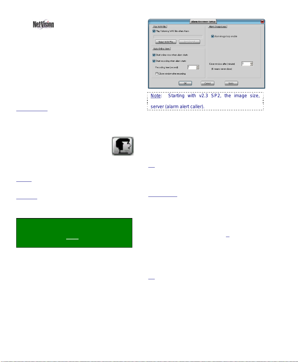
13.2
Setting Up the Alarm
Alert Receiver
Notice: This task pertains only to a remote station that
is identified through the alarm alert sender at a Video
Server.
The alarm alert feature includes a number of
configurable options--including having the
camera auto-display, and/or having recording
start automatically when an alarm alert is
received.
Notice: The Alarm Alert feature must also be enabled
and set up at the specific Video Server(s).
Related Topics
E-Mail; 15.2 Set Up the Alarm Alert Caller
To set up the alarm alert receiver, you must
first activate this software module:
Start your remote software, and log
in as usual. Then, click the Alarm
Alert icon (head/portrait) at the
bottom of the screen once.
TechTip: The Alarm Alert Receiver can also be run on
its own:
Startup
Netvision software (under C:\Program Files\Digital
Surveillance Recorder\...).
Shutdown
(head/portrait) on the right-hand side of the Windows
task bar, and select Exit.
--------------------------------------------------
Locator: Look for the face symbol (alarm
alert) near the right-hand end of the
Windows task bar, right-click it, and select
Setup.
Refer to the descriptions that follow while
working in this screen.
To Exit from this Screen: Click [Cancel] at the
bottom, or [X] in the upper-right corner.
: 15.1 Enable/Disable Alarm Alerts or
: Run Alarm Receiver.exe in the folder for your
: Right-click the Alarm Alert Receiver symbol
Note: Starting with v2.3 SP2, the image size,
number of frames, and frame interval are set at the
server (alarm alert caller).
Play WAV file
Play following WAV file when alarm: Select
this if you wish to have a sound played each
time an alarm alert is received from a Video
Server;
[Select WAV File]: Click this to allow
selecting a sound file (.WAV);
Tip: Sounds can typically be found under
"C:\Windows\Media".
[Test Sound]: Click this to hear your selected
sound file;
Audio Monitor: If you are also using the audio monitor
feature at the same time, the sound selected at the
Video Server will played at the remote station as well.
Recording Custom Sounds: On a PC equipped with
a microphone and sound card (or equivalent), open the
Windows [Start] menu, select [Run], type "sndrec32",
and click [OK]. Then, refer to the on-line help for the
sound recorder (press F1, or use the H
elp menu).
Auto Online View
Start online view when alarm starts: This
has the associated camera displayed in a
separate window automatically whenever an
alarm alert is received;
Tip: This uses the small remote module's camera
viewer. You will be asked to log in the first time this
feature is triggered. Note: When this viewer is closed,
you'll be asked if you want to "Clean up all Passwords".
Be sure to select "No" if you don't want to have to log in
the next time.
Start recording when alarm starts: This has
the displayed camera-view recorded
66 NetVision Plus/Elite and Micro DVR v2.3 SP2 User's Guide 21-0400E v2.3.3
Page 75
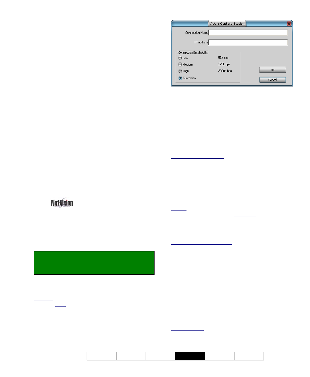
automatically whenever an alarm alert is
received;
Recording time (seconds): This sets the
duration for automatic alarm-alert recordings;
Close window after recording: Select this if
you want the camera window to close
automatically at the end of the recording time.
--------------------------------------------------
Alarm Image Loop
This causes the first 5-10 frames from the
associated camera to be included in a separate
window whenever an alarm alert is received.
Three image sizes are provided for each camera
type.
Alarm image loop enable: This enables the
"image loop" feature;
Close window after: This allows having the
window close automatically after 1 - 9999
minutes (0 = never). The window can also be
closed manually before this time expires.
Related Topics:
12 Configuration Introduction
13 Remote Station Configuration
15.1 Enable/Disable Alarm Alerts or E-Mail
15.2 Set Up the Alarm Alert Caller
13.3
Station List (Identifying the Video Servers)
Before you can view cameras remotely, you
must identify the associated Video Servers to
the remote station software.
Locator: (Logged in at a remote station),
Select: [Station List] near the top-right
corner of your screen.
Then, click [Add], and make your selections in
the next screen:
Attention: When finished entering information, click
[OK] (do NOT
press Enter).
Connection Name: Enter a suitable name for
the Video Server.
IP Address: Obtain this from someone at the
specific Video Server (xxx.xxx.xxx.xxx).
Connection Bandwidth: This sets the video
quality and frame rate as suitable for your
connection speed
modem, cable/DSL link, or a network connection)
Maximum Image Quality: Camera images are
transmitted based on the recording mode at the
NetVision™ Video Server (if presently being recorded
there), or per the present/last displayed image size for
any camera on the same capture board displayed at the
Video Server.
(i.e., associated with a dial up
.
(•) Customize: This opens another screen for
manually setting bandwidth parameters:
Quality: Sets the relative amount of video detail to be
included in non-key frames; Data Rate
maximum video data transmission rate to be used by
the connections with this specific NetVision video
server; Frame Rate
frames per second for the transmitted video images;
Keyframe every (x) seconds
often a complete frame is sent compared to only
changes from the previous frame. Lower values
provide better image quality and require more
bandwidth
: This sets the maximum number of
: This determines how
: This sets the
[OK]: Select this to complete the operation.
[Cancel]: Click this to abort.
Tip: You can change settings later by selecting
[Modify] in the station-list screen (or delete a Video
Server via [Remove] ).
------------------------------
When finished, click [Exit] to close the Video
Server screen.
Related Topics:
12 Configuration Introduction
13 Remote Station Configuration
21-0400E v2.3.3
Welcome Common Admin
Config
Install Tech-Ref
67
Page 76

14
General Video Server Settings
14.1
Startup / Logoff Options
A number of start-up/logoff options are
available at Video Server PCs.
TechTip: These settings do not affect features to
be available at remote surveillance stations.
Locator: (Logged in at the Video Server as
a "Supervisor"),
Select: [Utility], then [Option Setting].
Select Operation Setting , and then make
your desired selections:
--------------------------------------------------
On Next Startup:
• Status Restore
viewing / recording mode selections to be
retained for use during the next login.
(This also applies to the “At Logoff”
selections, to follow/below).
• Auto Login
having to logon when the Video Server
software is started (and select to be logged
in as "Operator" or "Super").
Caution: This bypasses password protection for
the Video Server software. Auto-logon as "Super"
gives full access for anyone with authority to use the
PC (as per Windows 2000/XP permissions).
BIOS and Windows Setup: Video Servers are
typically pre-set at the factory to automatically
restart after a power failure.
At Logoff: Select the items that you wish to
remain in effect at the Video Server when the
operator logs off (video display, manual
recording, PTZ control).
TechTip: If you need to disable remote viewing
through a dial-up connection, disconnect or disable
the modem.
Allow Operator to Exit: Select this to allow
persons logged in as "Operator" to be able to
shut down the software. (Otherwise, the [Exit]
button is available only when logged on as a
"Supervisor".)
: Select this if you want
: Select this if you want to skip
Date/Time Display: 12-hour (with AM/PM)
versus 24-hour time display.
--------------------------------------------------
When finished, click [OK], and then
[Close] the utility menu.
14.2
Miscellaneous Settings
A number of miscellaneous settings are
provided.
Locator: At the Video Server PC (will
prompt for "Supervisor" login),
Select: (Windows task bar) Start, Settings,
Control Panel, DSR Configuration.
Desktop Link: There should also be a link to this on
your desktop called "NetVision Configuration".
Tips: If you cannot access the Windows task bar,
press Ctrl-Esc (or your 'Windows' key). To view the
names for items on the task bar, click a blank area on
the bar, and then 'hover' your mouse pointer over each
item.
Logon as a "Supervisor" when prompted.
Then, double-click Optional Features Setup
in the list. When the screen appears, select
Misc. , and then make your desired
selection(s).
--------------------------------------------------
Allow minimization of the main window:
This enables (or disables) the right-click menu
for the NetVision desktop.
When enabled, you will be able to right-click a blank
portion of the NetVision desktop to Minimize the
NetVision program, or view the Help.
Enable Audit Trail Log: This enables (or
disables) the logging of changes made through
the [Utility] button.
Related Topic: 11.5 Viewing Changes Made through
the "Utility" Menu
Enable DSR Http Server Log: This enables
(or disables) the HTTP server log.
Tip: This is typically used internally for diagnostic
purposes only.
Enable TV Mux: This enables (or disables)
the TV-out feature (Spot Monitor).
Related Topics:
8.4 Monitoring Cameras via TV (Spot Monitor)
68 NetVision Plus/Elite and Micro DVR v2.3 SP2 User's Guide 21-0400E v2.3.3
Page 77
--------------------------------------------------
When finished, click [OK], and then click
[X] to close the list (upper-right corner).
Attention: To recognize any DSR Configuration
changes made while the Video Server software is
running, you may need to restart the software.
14.3
Setting Video Playback Sessions to be Logged
You can optionally have remote playback
sessions logged at each Video Server.
Locator: (Video Server running, Windows
'Task Bar' in view).
Double-click DSR Playback Server on the
Video Server task bar.
Tips: If you cannot access the Windows task bar,
press Ctrl-Esc (or your 'Windows' key). To view the
names for items on the task bar, click a blank area on
the bar, and then 'hover' your mouse pointer over each
item.
When the screen appears, make your desired
selection(s).
--------------------------------------------------
Record to Log File: Select this to have user
video playback sessions recorded in a log file.
Filename and Location:
d:\dsr-video\Log\PlaybackServer\yyyymmdd.txt
-------------------------------------------------When finished, click [Close]
.
Related Topics: 11.6 Viewing Remote User Sessions
21-0400E v2.3.3
Welcome Common Admin
Config
Install Tech-Ref
69
Page 78

15
Alarm / Reporting Settings
External Inputs/Sensors: For details on setting up
external sensors, refer to:
18.3 External Sensors and Recording Duration.
15.1
Enable/Disable
Alarm Alerts or E-Mail
The alarm alert feature lets a remote
surveillance station know any time an alarm
occurs (external sensor tripped, video motion
sense, and/or video signal lost).
A recording of the scene will also be available
at the Video Server PC.
This feature operates through an IP
connection, and can also alert persons via
email (with or without a 'snapshot' of the first
frame of the alarm-triggered recording).
TechTip: This feature must also be set up through
the Alarm Alert Caller module on the taskbar, and
the Video Server must be able to communicate with
the remote station (via IP). As well, the Alarm Alert
feature can be customized as desired at the remote
stations (see "Related Topics").
Note: This feature works only in conjunction with
alarm-based recording (motion-detection and/or via
an external input for each camera).
Related Topic:
18 Scheduled and/or Alarm-Triggered Recording
Locator: At the Video Server PC (will
prompt for "Supervisor" login),
Select: (Windows task bar) Start, Settings,
Control Panel, DSR Configuration.
Desktop Link: There should also be a link to this on
your desktop called "NetVision Configuration".
Tips: If you cannot access the Windows task bar,
press Ctrl-Esc (or your 'Windows' key). To view the
names for items on the task bar, click a blank area on
the bar, and then 'hover' your mouse pointer over each
item.
Logon as a "Supervisor" when prompted.
Then, double-click Optional Features Setup
in the list. When the screen appears, select
Alarm Alert , and then make your desired
selection(s).
Alarm Alert
Enable Alarm Alert: Select this to activate
the alarm alert (and/or Alarm Email) feature.
Enable Alarm Email: This turns the alarm-
email feature on (or off).
Sender Information
Name: This shows the name (or IP address)
of the Netvision Video Server PC;
From: This is the outgoing email address;
Server Information
SMTP Server: This is the name of your
outgoing SMTP email server. (Get this from
your network administrator or email service
provider.)
My server requires authentication: Select
this, and enter an account name (outgoing
email address) and password if required for
your outgoing email;
70 NetVision Plus/Elite and Micro DVR v2.3 SP2 User's Guide 21-0400E v2.3.3
Page 79

Dial-up E-Mail Connection: This is handled through
your e-mail settings (nothing else needs to be set in
Netvision).
Note: Web-page-based e-mail services are NOT
supported at the Video Server.
Alarm Message
To and Cc: These are the email addresses of
the person(s) who are to receive the email
alerts from this Video Server (e.g.,
jmartin@mailco.com).
For Multiple "To" or "Cc" Recipients: Use a
semicolon (;) or comma (,) between the addresses (with
NO spaces).
Enable snapshot attachment: Select this to
have a 'snapshot' of the first frame of the
alarm-triggered recording included in the email. To set the size of the snapshot, click the
[T].
--------------------------------------------------
When finished, click [OK], and then click
[X] to close the list (upper-right corner).
Attention: To recognize any DSR Configuration
changes made while the Video Server software is
running, you may need to restart the software.
Testing Your Settings: To send a sample
email, right-click the Alarm Email Sender on
the Windows Taskbar, and select Test.
Related Topics:
6.2 Responding to Alarm Alerts (Remote Station)
11.2 Remote Users and Permissions
(+ HTTP Server Port);
13.2 Setting up the Alarm Alert Receiver
(Remote Station)
15.2 Set Up the Alarm Alert Caller
18 Scheduled and/or Alarm-Triggered Recording
21 Network and Connectivity Issues
21-0400E v2.3.3
Welcome Common Admin
Config
Install Tech-Ref
71
Page 80

15.2
Set Up the
Alarm Alert Caller
The alarm alert feature lets a remote
surveillance station know any time an alarm
occurs (external sensor tripped, video motion
sense, and/or video signal lost).
A recording of the scene will also be available
at the Video Server PC.
This feature can be set regarding:
• The cameras to be monitored for this
(v2.3 SP2);
• The number of 'pre-alarm' frames to
keep/show
• The type of connection;
• The type of events to trigger alarm alerts;
• An optional sound (WAV file) to include.
• Image size and other video parameters
(v2.3 SP2).
TechTip: The "Alarm Alert" feature must also be
enabled, and the Video Server must be able to
communicate with the remote station (via IP). (see
"Related Topics").
Locator: (Video Server running, Windows
'Task Bar' in view).
Right-click Alarm Alert Caller on the
taskbar, and select Setup.
Tips: If you cannot access the Windows task bar,
press Ctrl-Esc (or your 'Windows' key). To view the
names for items on the task bar, click a blank area on
the bar, and then 'hover' your mouse pointer over each
item.
When the screen appears, make your desired
selection(s).
(v2.3 SP2);
15.2.1
Left Side of the Screen
Alarm Alert Receiver Name / IP: This is the
name or IP address of the remote station PC
which is to receive the alarm alerts.
To obtain the Remote station's IP address: Have
someone go to THAT computer, open a DOS /
Command window, type ipconfig, and press
Enter. (To close the window, type exit, and press
Enter). Note: For this feature, the remote station
must have a fixed/static IP address.
Connection Mode: Select LAN if the Video
Server and remote station are on the same
network (LAN/WAN), or to have "alarm alerts"
sent through a permanent internet connection.
Select Dial-up if the Video Server will have to
initiate a dial-up networking connection.
Primary Connection: For a dial-up
connection. Type the exact name of the MS
Windows ‘dial-up connection’ to be used by the
Alarm Alert Caller. This must either be set up
previously, or type the name here, and then
ensure an MS Windows dial-up connection is
set up using the same name.
Tip: To check the spelling for existing dial-up
connections, click [Dial-up Connections Setting] (to
follow / below).
Backup Connection: (Optional). For a dialup connection. Type the exact name of a
second dial-up connection to be used if a
72 NetVision Plus/Elite and Micro DVR v2.3 SP2 User's Guide 21-0400E v2.3.3
Page 81
connection cannot be made via the “Primary
Connection”.
Note: If the “Primary Connection” is misspelled, and
the “Backup Connection” is either blank or misspelled,
the Alarm Alert Caller will try to use the first connection
it finds under “Control Panel, ÖNetwork Connections”
using an alphabetical sort.
[Dial-up Connections Setting]: Opens an
MS Windows screen that allows you to test or
check the name/spelling of dial-up networking
connection(s) that were set up previously, or
set up a new one (via [Settings], Ö[Add] ).
(See "Related Topics", to follow / below).
--------------------------
Notification on Event: Select the type of
alarm-alerts to be sent to the remote station
(external alarm / sensor, video motion
detection, and/or video lost/recovery).
Play Following WAV File when Alarm: This
sets a custom sound to play at the Video
Server each time an alarm-alert is sent. Click
[Select WAV File], locate and select the file
(typically under C:\Windows\Media), and click
[OK]. To listen to your selection, click [Test
Sound].
Remote Audio: If the remote station is also
monitoring audio from this Video Server, the sound
(WAV file) selected above will play at the remote
station as well.
Related Topics: 16.7 Remote Audio Monitoring
Recording Custom Sounds: On a PC equipped
with a microphone and sound card (or equivalent),
open the Windows [Start] menu, select [Run], type
"sndrec32", and click [OK]. Then, refer to the online help for the sound recorder (press F1, or use
the Help menu).
15.2.2
Right Side of the Screen
Notification on Camera
- The cameras selected here ( 9) will be
monitored for the Alarm Alert feature. De
-select
any that you do NOT want to be monitored for
alarm alerts.
Alarm Image Loop Setup (for PAL vs. NTSC)
- This sets the size for Alarm Alert video clips.
-----------
- Number of Frames: This is the number of
frames to be displayed (2 - 10) starting when the
alarm occurred;
- Number of Pre-Alarm Frames: This is the
number of frames to be displayed (1 - 5) from
just before
Note: This requires "pre-alarm recording" to be
enabled (since the 'pre-alarm' frames are taken
from those files).
File Location: When an alarm-alert occurs, the
images are stored under: "d:\Dsr-Video\Dsr-
Webroot\ CameraJpegImage\Camera", where "d" is
the drive that contains the operating system
(typically "C:").
Attention: Do NOT set this to 0 (zero). To disable
this feature, ensure "pre-alarm recording" is NOT
enabled.
Related Topic:
18.4 Setting up Pre-Alarm Recording
the alarm occurred;
- Frame interval: This sets the duration
between frames when captured (500 - 5000
ms; i.e., ½ to 5 seconds).
Tip: The frames are also displayed at a similar speed.
15.2.3
Bottom of this Screen
- [OK]: This saves your settings and closes this
screen.
- [Cancel]: Click this to abort your entries,
leaving this screen in its previous state.
- [Apply]: This applies and saves your settings
without closing this screen.
Attention: To recognize any changes made in DSR
Configuration while the NetVision Video Server
software is running, you may need to restart the
software.
--------------------------------------------------
When finished, click [OK].
Related Topics:
6.2 Responding to Alarm Alerts (Remote Station)
13.2 Setting up the Alarm Alert Receiver
15.1 Enable/Disable Alarm Alerts or E-Mail;
(Remote Station);
18 Scheduled and/or Alarm-Triggered Recording
21 Network and Connectivity Issues (includes Dial-Up)
21-0400E v2.3.3
Welcome Common Admin
Config
Install Tech-Ref
73
Page 82

15.3
(v2.3 SP2)
This feature causes cameras to be displayed
automatically on the Video Server desktop
whenever an external alarm is triggered, or
motion is detected at selected cameras.
Note: This feature works only in conjunction with
alarm-based recording (motion-detection and/or via
an external input for each camera).
Related Topic:
18 Scheduled and/or Alarm-Triggered Recording
Locator: At the Video Server PC (will
prompt for "Supervisor" login),
Select: Windows Control Panel,
ÖDSR Configuration, ÖAuto Alarm
Display.
Auto Alarm Display
- Enable Auto Alarm Display: This turns this
feature on [9] and off [ ].
Display for Alarm Type
- External Alarm: Select this if you want an
external alarm at the selected cameras to trigger
this feature.
Also See: 25.3 Wiring Reference
- Motion: Select this if you want motion-detection
at the selected cameras to trigger this feature.
Also See:
11.3 Viewing a List of Motion-Detection Alarms
18.5 Setting up Video Motion-Detection
Display for Camera
- (check-box for each camera): Select each of
the cameras that you want to be monitored for
this feature.
- Suspend Sequencing When Alarm: This
stops on-screen sequencing while alarmtriggered cameras are being displayed to ensure
they remain on-screen until the alarm recording
ends.
Tip: If multiple cameras are triggered, they will
appear on-screen in the order they were triggered.
------------------------
- [OK]: Click this to save your settings.
- [Cancel]: Click this to abort your entries,
leaving this screen in its previous state.
Attention: To recognize any changes made in DSR
Configuration while the NetVision Video Server
software is running, you may need to restart the
software.
74 NetVision Plus/Elite and Micro DVR v2.3 SP2 User's Guide 21-0400E v2.3.3
Page 83
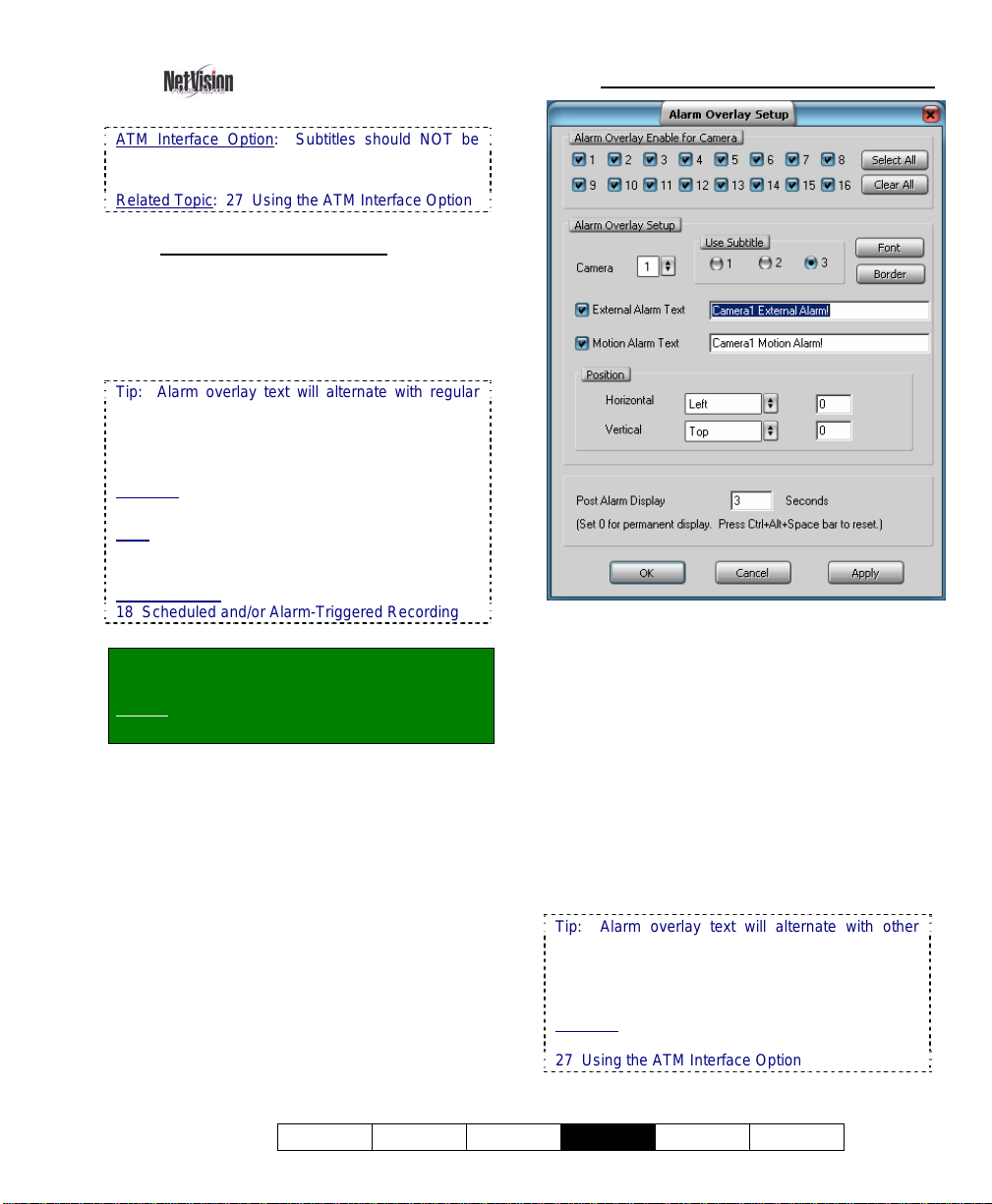
15.4
(v2.3 SP2)
ATM Interface Option: Subtitles should NOT be
used with the ATM Interface option as they may
interfere with ATM overlays.
Related Topic: 27 Using the ATM Interface Option
15.4.1
About Alarm Overlays
Set Up Alarm Overlays
You can define special alarm-overlay subtitles
to appear on camera images whenever an
alarm is triggered externally (hardwired inputs),
or when motion is detected at each selected
camera.
Tip: Alarm overlay text will alternate with regular
subtitles (of the same subtitle number) until the
overlay expires. These can also be cleared by
pressing Ctrl-Alt-Spacebar to return to the regular
subtitles.
Also See: 16.1.3 [Subtitle Setter] (Custom Titles
for Cameras)
Note: This feature works only in conjunction with
alarm-based recording (motion-detection and/or via
an external input for each camera).
Related Topics:
18 Scheduled and/or Alarm-Triggered Recording
Locator: At the Video Server PC (will
prompt for "Supervisor" login),
Select: Windows Control Panel,
ÖDSR Configuration, ÖAlarm Overlay.
15.4.2
The Alarm Overlay Setup Screen
Alarm Overlay Enable for Camera
- (check-box for each camera): Select each of
the cameras that you want to be monitored for
this feature.
- [Select All]: Click this to select all cameras [9].
- [Clear All]: Click this to deselect all cameras
[ ].
Alarm Overlay Setup
- Camera, and "Use Subtitle": This determines
which camera and subtitle number that the rest
of the settings on this screen will affect. (Select
each camera in turn, and then set (or view) the
various parameters for each one.)
Tip: Alarm overlay text will alternate with other
subtitles (of the same subtitle number) until the
overlay expires (as per "Post Alarm Display" setting,
to follow). These can also be cleared by pressing
Ctrl-Alt-Spacebar to return to the regular subtitles.
Also See: 16.1.3 [Subtitle Setter] (Custom Titles
for Cameras)
27 Using the ATM Interface Option
21-0400E v2.3.3
Welcome Common Admin
Config
Install Tech-Ref
75
Page 84

- [Font]: Allows selecting a specific font
(typeface) plus size, colour, etc. for the present
alarm overlay (per the selected camera and
subtitle number).
- [Border]: This allows adding a border to the
present alarm overlay (per the selected camera
and subtitle number).
- External Alarm Text: The checkbox on the left
enables an alarm overlay for this camera when
triggered by its external alarm input. Enter your
desired overlay text on the right.
Also See: 25.3 Wiring Reference
- Motion Alarm Text: The checkbox on the left
enables an alarm overlay when motion is
detected at this camera. Enter your desired
overlay text on the right.
Also See:
11.3 Viewing a List of Motion-Detection Alarms
18.5 Setting up Video Motion-Detection
- Position: This allows setting where the title will
appear on the camera-image:
Horizontal: This allows setting the left-to-right starting
position for the title.
Vertical: This allows setting the top-to-bottom
position for the title.
Tip
: For an absolute position, select Custom for
the vertical and/or horizontal, and then enter a
specific value in the area(s) provided (in pixels,
relative to your screen resolution). These numeric
fields are ignored otherwise.
- Post Alarm Display: This sets how long the
alarm overlay subtitle will remain on-screen after
the alarm condition stops (motion detection or
external alarm).
Range: 1 - 999,999,999 seconds. 0 = Remains in
effect until cleared via Ctrl-Alt-Spacebar. You will
be 'returned' to the regular subtitles.
------------------------
- [OK]: This saves your settings and closes this
screen.
- [Cancel]: Click this to abort your entries,
leaving this screen in its previous state.
- [Apply]: This applies and saves your settings
without closing this screen.
Attention: To recognize any changes made in DSR
Configuration while the NetVision Video Server
software is running, you may need to restart the
software.
76 NetVision Plus/Elite and Micro DVR v2.3 SP2 User's Guide 21-0400E v2.3.3
Page 85
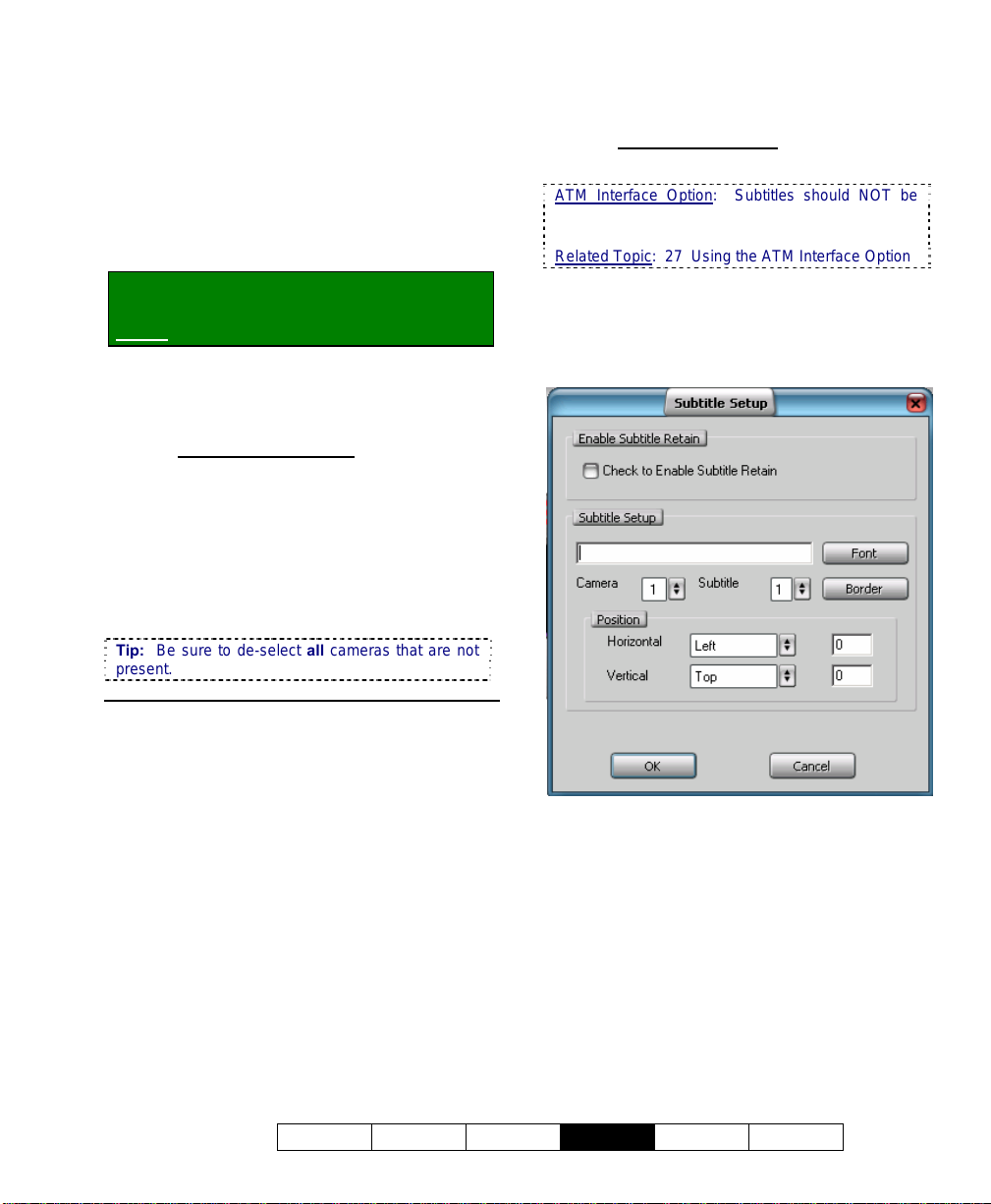
16
Camera, Audio, and PTZ Settings
16.1
Set up Cameras and Titles
You can set the name to be associated with
each camera. Cameras that are physically
connected to a Video Server also need to be
activated, and all other camera numbers
MUST be de-activated.
Locator: (Logged in at the Video Server as
a "Supervisor"),
Select: [Utility], then [Camera Setting].
When the screen appears, make your desired
selection(s).
--------------------------------------------------
16.1.1
(List of Cameras)
Cam ID: This is each camera number/ID
pertaining to the physical connections to the
Video Server
(see "Related Topics").
Camera Title: Enter a suitable description for
the camera location/view.
Active: Select this (only) for each camera
that is connected to your Video Server.
Tip: Be sure to de-select all cameras that are not
present.
16.1.3
[Subtitle Setter]
(Custom Titles for Cameras)
ATM Interface Option: Subtitles should NOT be
used with the ATM Interface option as they may
interfere with ATM overlays.
Related Topic: 27 Using the ATM Interface Option
Each camera can have up to 3 custom titles
associated with it. These titles can be
positioned anywhere in the camera-view, and
are visible at the Video Server and remote
stations.
16.1.2
[Video Control]
This allows controlling the brightness, and
colour balance for each camera to adjust for
different lighting conditions, etc. The
selections include Camera, Brightness,
Contrast, Saturation U, Saturation V, and
Hue.
[Default]: This returns to the default colour parameters
for the selected camera.
21-0400E v2.3.3
Welcome Common Admin
Enable Subtitle Retain
Check to Enable Subtitle Retain: Select this
to have the titles retained whenever the
NetVision software (and/or Video Server) is
restarted.
Subtitle Setup
st
1
Field (Title Text): Select a camera and
subtitle number, and then enter the text for
your camera title here;
[Font]: This allows selecting different styles of
letters;
Config
Install Tech-Ref
77
Page 86

[Border]: This allows selecting a border for
the title if desired;
Camera: Select the camera number here
(1 - 16).
Subtitle: Select the subtitle number for the
selected camera (1 - 3):
Position: This allows setting where the title
will appear on the camera-image:
Horizontal: This allows setting the left-to-right starting
position for the title.
Vertical: This allows setting the top-to-bottom position
for the title.
Tip
: For an absolute position, select Custom for the
vertical and/or horizontal, and then enter a specific
value in the area(s) provided (in pixels, relative to your
screen resolution).
Alarm Overlay
can be set up to appear for individual cameras
when motion is detected, or an external alarm
occurs.
Related Topic:
15.4 Set Up Alarm Overlays (v2.3 SP2)
--------------------------------------------------
(v2.3 SP2): Special camera subtitles
When finished, click [OK] as needed, and
then [Close] the utility menu.
PTZ Cameras: These must also be set up through
"DSR Configuration" (in the Windows Control
Panel). (see "Related Topics").
IP Cameras and Network Video Servers (NVS):
This support and related set up is covered
separately. (see "Related Topics").
Related Topics:
16.3 Pan/Tilt/Zoom Activation and Set Up
16.4 Show Date and Time in Video Image
(Time Stamp)
25.2 Camera and PTZ Reference
30 Setting up an IP Camera (or Video Server
module)
16.2
Cameras to Appear in Sequential Viewing
You can select the cameras for sequential
viewing, and set the duration that cameras will
be displayed.
Locator: (Logged in at the Video Server as
a "Supervisor"),
Select: [Utility], then [Option Setting].
Select Sequence Setting , and then make
your desired selections:
--------------------------------------------------
Dwell Time: The duration that each camera
will be displayed during sequential viewing.
Sequencing (Cam ID): Select the cameras to
be included for sequential viewing.
--------------------------------------------------
When finished, click [OK], and then
[Close] the utility menu.
Related Topics:
25.2 Camera and PTZ Reference
16.1 Set up Cameras and Titles
78 NetVision Plus/Elite and Micro DVR v2.3 SP2 User's Guide 21-0400E v2.3.3
Page 87

16.3
Pan/Tilt/Zoom Activation and
Set Up
Cameras with pan/tilt/zoom (PTZ) control are
fully supported. This feature must be enabled
and properly set up.
TechTips: Beginning with V2.2, eight different PTZ
protocols are supported through COM ports 1 - 8
(different protocol for each port).
V2.3 remote stations can control PTZ cameras from
V2.1, V2.2, and V2.3 NetVision Video Servers.
Locator: At the Video Server PC (will
prompt for "Supervisor" login),
Select: (Windows task bar) Start, Settings,
Control Panel, DSR Configuration.
Desktop Link: There should also be a link to this on
your desktop called "NetVision Configuration".
Tips: If you cannot access the Windows task bar,
press Ctrl-Esc (or your 'Windows' key). To view the
names for items on the task bar, click a blank area on
the bar, and then 'hover' your mouse pointer over each
item.
Logon as a "Supervisor" when prompted.
Then, double-click PTZ Configuration. When
the screen appears, make your desired
selection(s):
Tip: After [Apply]-ing settings for all needed ports,
click [Camera Table] to set the camera/port
assignments.
--------------------------------------------------
Enable PTZ: Select this ( 9 ) to allow
pan/tilt/zoom control for cameras that support
this feature.
Com Port: Select the serial (COM) port on the
Video Server being used for PTZ camera
control.
Model: Select your desired PTZ protocol here
(must be different protocol for each port used).
Baud Rate, Data, Parity, Stop, and Flow
Control: These are serial communications
parameters that MUST be set to match the
requirements of the PTZ camera (refer to the
camera documentation, and/or:
Look Here: 25.2.4 PTZ Model Reference).
[Show / Hide Details]: Opens the bottom
portion of the screen showing the settings that
have been applied for each port.
[Camera Table]: This opens a screen that
allows setting the COM port associated with
each PTZ camera, and identifying cameras
within the PTZ sequence. (When finished,
click [OK].)
Steps
: • Click [Show Details]; • Select a
port; • Set the model and communications
parameters; • Click [Apply].
21-0400E v2.3.3
Welcome Common Admin
Camera ID: This pertains to the camera's OSRD /
receiver-driver ID setting in the hardware (where
applicable), or it's PTZ sequence number for the
specific port (xth camera).
Config
Install Tech-Ref
79
Page 88

Com Port: For each PTZ camera, select the
associated COM port here; PTZ Cameras Connected
in parallel
Individual camera control is provided through an OSRD
/ receiver-driver ID setting for each camera, or through
a supported 'cascade' protocol (such as Canon VC-C4).
IP Cameras / NVS (v2.3 SP2)
connected via IP must use the same PTZ
protocol. Select COM6 for these cameras, and
ensure COM7 is left free (for internal
communications). Daisy-chain PTZ wiring.
Individual cameras are identified for PTZ control by
the camera ID in the Camera Table.
Related Topics: 30 Setting up an IP Camera (or
Video Server module)
Alarm (9), and PTZ Preset (#): This allows setting a
camera to jump to a specific PTZ preset position (if
defined) whenever its associated external input is
tripped. In the ‘row’ for each specific camera, click the
“Alarm” indicator (9) to enable this feature, and then
enter the number of the desired PTZ preset.
Related Topics
18.3 External Sensors and Recording Duration
25.3 Wiring Reference
--------------------------------------------------
: In this case, the COM port will be the same.
: ALL PTZ cameras
: 8.3.4 Other PTZ Features
When finished, click [OK], and then click
[X] to close the list (upper-right corner).
Attention: To recognize any DSR Configuration
changes made while the Video Server software is
running, you may need to restart the software.
Note: Also ensure all cameras that are present (only)
are enabled under [Utility] Ö [Camera Setting].
(Requires "Supervisor" login.)
Also See
8.3 Changing a Camera's View (Pan/Tilt/Zoom)
16.1 Set up Cameras and Titles
25.2 Camera and PTZ Reference
26.4 Testing PTZ Cameras at a Video Server
:
16.4
Show Date and Time in Video Image (Time Stamp)
You can select whether or not individual
camera images will include a date and time
display.
Locator: At the Video Server PC (will
prompt for "Supervisor" login),
Select: (Windows task bar) Start, Settings,
Control Panel, DSR Configuration.
Desktop Link: There should also be a link to this on
your desktop called "NetVision Configuration".
Tips: If you cannot access the Windows task bar,
press Ctrl-Esc (or your 'Windows' key). To view the
names for items on the task bar, click a blank area on
the bar, and then 'hover' your mouse pointer over each
item.
Logon as a "Supervisor" when prompted.
Then, double-click Optional Features Setup
in the list. When the screen appears, click
Time Stamp Setup , and then make your
desired selection(s).
--------------------------------------------------
Time Stamp for Camera
9 ) For each camera image to include the
(
date and time.
--------------------------------------------------
When finished, click [OK], and then click [X] to
close the list (upper-right corner).
Especially for the Video Server, it is important
to ensure that the date and time are always
correct--since this information is used to
manage video recordings. There is normally
no reason for this to vary, but it's still best to
check it on a regular basis.
Tips: The time is displayed on the right-hand end
of the Windows task bar. To view the date, 'hover'
the mouse pointer over the time. For details on
setting the date or time, open the Windows on-line
help (e.g., from the Windows Control Panel), and
search for "Date".
Attention: To recognize any DSR Configuration
changes made while the Video Server software is
running, you may need to restart the software.
Also See: 7.9.6 Utility Button (Quad Playback)
16.1 Set up Cameras and Titles
28.7 Window Options and File Properties
(Quad Playback--Micro DVR)
80 NetVision Plus/Elite and Micro DVR v2.3 SP2 User's Guide 21-0400E v2.3.3
Page 89

16.5
Enable Audio for Specific
Cameras
Audio recording and playback is supported
through up to 5 audio inputs included on the
Video Server PC. This requires
microphone(s), plus PC speakers plugged into
the green audio output on the back of the
Video Server PC. Bare microphones
connected to line-level audio inputs will each
require a suitable microphone ‘pre-amp’.
Related: 25.1 Capture Board Reference
Camera(s) to be associated with audio must be
identified as such (to follow).
Audio Recording: Audio is not recorded as a
separate file. Instead, it is included in any local or
remotely recorded AVI (or MPEG) files for the
specific camera.
Legal Notice: The recording of live audio is subject
to local bylaws. Be sure to find out if audio
recording is restricted in your area before
proceeding.
Locator: (Logged in at the Video Server as
a "Supervisor"),
Select: [Utility], then [Option Setting].
Select Audio Setting , and then make your
desired selections:
--------------------------------------------------
Camera 1-16: Select the audio source for
each specific camera. This will be "None",
"Sound Card", or #1, 2, 3, or 4 for a capture
board that includes an audio input (or for
inputs on the optional 4-input audio card).
--------------------------------------------------
When finished, click [OK], and then
[Close] the utility menu.
Tip: For good audio recording and playback, you
may need to adjust the audio levels.
Related Topics:
16.6 Setting the Sound Level
16.7 Remote Audio Monitoring
25.1 Capture Board Reference
16.6
Setting the Sound Level
For good quality audio recording and playback,
you may need to adjust the audio levels. This
is done using the Windows recording volume
control.
Locator: To access the Windows recording
and playback volume controls, select:
Windows [Start] menu, Settings, Control
Panel, Multimedia (or [Start], Run,
"sndvol32", [OK] ).
Note: If you cannot access the Windows "Start" menu,
press "Ctrl-Esc" (or your "Windows" key).
Use the Windows recording volume control to
adjust the audio levels as desired.
This should be done with a range of loud and soft
sounds in the area (to ensure soft sounds are being
heard, and loud sounds are not distorting).
--------------------------------------------------
When finished, close the recorder/multimedia
screens as necessary.
Tip: You must also indicate which camera(s) are
associated with audio (see "Related Topics").
Related Topics:
16.5 Enable Audio for Specific Cameras
16.7 Remote Audio Monitoring
25.1 Capture Board Reference
21-0400E v2.3.3
Welcome Common Admin
Config
Install Tech-Ref
81
Page 90

16.7
Remote
Audio Monitoring
Current Video Server PCs include up to 5
audio inputs, allowing some camera(s) to have
sound included with the camera image (and in
associated video recordings). These sounds
can also be monitored at the Video Server PC
and at any authorized remote stations.
Multimedia Settings: Listening to audio through a
microphone is subject to Windows multimedia
settings for recording and playback (mute, volume,
etc.). Remote Stations must be equipped with a
sound card (or equivalent) and speakers. (A sound
card is already built into Video Servers.)
Audio Recording: Audio is not recorded as a
separate file. Instead, it is included in any local or
remotely recorded AVI (or MPEG) files for the
specific camera.
Legal Notice: The recording of live audio is subject
to local bylaws. Be sure to find out if audio
recording is restricted in your area before
proceeding.
16.7.1
Network / Connection Set Up
The remote station must be able to
communicate with the Video Server (via its IP
address).
Related Topics: 21 Network and Connectivity Issues
16.7.2
Microphone and Speakers
Connect the microphone and speakers to the
appropriate/correct jacks on the back of the
Video Server. Bare microphones to connect to
through a line-level audio input (video capture
board or audio input board) will each require a
suitable pre-amp.
Related: 25.1 Capture Board Reference
Push Button: The microphone can have a
direct/permanent connection, or it can be controlled
through a push-button or switch (e.g., for a one-way
A/V intercom application).
16.7.3
Video Server Set Up
1) Enable audio for the specific camera(s).
Related Topics:
16.5 Enable Audio for Specific Cameras
2) Adjust the sound level at the Video
Server if required.
Related Topics: 16.6 Setting the Sound Level
3) Set up permissions to determine who
can access the audio server.
Related Topics:
11.2 Remote Users and Permissions
(includes PTZ priority +HTTP Server Port)
4) Since all sounds handled by the Video
Server's sound card will be heard at
the remote stations, it is best to turn
off the sounds associated with MS
Windows (at the Video Server).
Details: Go to the Windows Control Panel, and run
"Sounds and Multimedia". Then, click the [T]
next to "Schemes", select "No Sounds", and click
[OK].
( Ö )
82 NetVision Plus/Elite and Micro DVR v2.3 SP2 User's Guide 21-0400E v2.3.3
Page 91

16.7.4
Remote Station: Initiate an
Audio Monitoring Session
To begin monitoring audio from a Video
Server, you need to activate the 'Audio Client',
and log-on to the desired Video Server.
Tip: Multiple audio sessions can be set up if you
will be monitoring more than one Video Server.
Note: This feature is NOT supported through the
small remote module software.
Alarm_Alerts: If using the alarm-alert feature at the
same time, a WAV file selected at the Video Server will
play at the remote station when the alarm-alert is
received (in addition to a WAV file selected at the
remote station (if applicable). Related Topics
15.1 Enable/Disable Alarm Alerts or E-Mail
--------------------------------------------------
A) Start the NetVision Remote
Station software, and log in
(with a username and
password that is registered at
the server). Then, click the 'Audio
Client' symbol (near the bottom-right).
If nothing seems to happen: Minimize the remote
station desktop to ensure the audio monitor is not
'behind' it.
B) When the screen appears, enter (or
select) the IP address of the desired
Video Server, and click [Logon].
Tip: Watch for the "Audio Source" box to change
to white, and [Logon] to change to [Logoff].
:
C) Under Audio Source, select Sound
Card (or other audio source such as
#1,2,3,4 for a capture board with an
audio input or inputs on an optional 4input audio card), and click [Start].
Tip: Watch for a short green bar to appear at
the bottom.
Related: 25.1 Capture Board Reference
D) Adjust the sound level on your PC if
required.
Related Topics: 16.6 Setting the Sound Level
: If you are unable to detect any sounds:
Note
• Ensure there is sound in the area of the
microphone;
• Check to ensure the sounds can be heard at the
Video Server (microphone and speakers must be
plugged in);
• Re-check the set-up details throughout this topic.
E) Use the [Stop] button if you wish to
stop monitoring the sound briefly.
When you're ready to end the
monitoring session, click [Logoff],
and/or click the [X] (top right) to close
the screen.
Note: If nothing seems to happen (or you get an
error), ensure the Video Server is on-line, re-check
your network/connection, and then try again.
Related Topics:
21 Network and Connectivity Issues
21-0400E v2.3.3
Welcome Common Admin
Config
Install Tech-Ref
83
Page 92

17
Recording and Playback Settings
17.1
Video Setup (in DSR Configuration)
Some settings are provided to improve video
quality in certain situations (jumpy camera
images, or fast motion all full resolution).
Locator: At the Video Server PC (will
prompt for "Supervisor" login),
Select: (Windows task bar) Start, Settings,
Control Panel, DSR Configuration.
Desktop Link: There should also be a link to this on
your desktop called "NetVision Configuration".
Tips: If you cannot access the Windows task bar,
press Ctrl-Esc (or your 'Windows' key). To view the
names for items on the task bar, click a blank area
on the bar, and then 'hover' your mouse pointer
over each item.
Logon as a "Supervisor" when prompted.
Then, double-click Video Setup in the list.
When the screen appears, make your desired
selection(s).
--------------------------------------------------
Single Field
Single Field Full Resolution: Select this to
prevent distortion of fast moving objects in
"Super Resolution" recordings.
Note: This will produce clearer images of fast
moving objects, while also reducing the resolution
from 640 x 480 to 640 x 240.
Video Sync Adjust
Number of Frames to Wait for
Synchronization: This is the number of
frames to be used for video synchronization (115 frames; Default: 2). This setting can help
to correct 'jumpy' camera images.
Note: Since increasing this value will reduce the
maximum possible frame rate in recordings, it is
best to try to find the smallest increase that provides
the desired image quality.
Video Quality - PCI Traffic Control
32-bit PCI Slot: Ensure this is selected.
64-bit PCI Slot: Future use.
--------------------------------------------------
When finished, click [OK], and then click [X] to
close the list (upper-right corner).
Attention: To recognize any DSR Configuration
changes made while the Video Server software is
running, you may need to restart the software.
Related Topics
9 Recording Camera-Views
17.2 Recording Setup (in DSR Configuration
17.3 Resolution and Recording Mode
18 Scheduled and/or Alarm-Triggered Recording
25.2 Camera and PTZ Reference
17.2
:
Recording Setup
(in DSR Configuration)
A number of settings pertaining to video
recording are provided under "Recording
Setup".
Locator: At the Video Server PC (will
prompt for "Supervisor" login),
Select: (Windows task bar) Start, Settings,
Control Panel, DSR Configuration.
Desktop Link: There should also be a link to this on
your desktop called "NetVision Configuration".
Tips: If you cannot access the Windows task bar,
press Ctrl-Esc (or your 'Windows' key). To view the
names for items on the task bar, click a blank area
on the bar, and then 'hover' your mouse pointer
over each item.
Logon as a "Supervisor" when prompted.
Then, double-click Recording Setup in the
list. When the screen appears, make your
desired selection(s).
17.2.1
Drive Usage
You can select the hard drive(s) to be used for
recording, allowing the system to use a
different drive if one becomes full. Local drives
and 'mapped' network drives are both
supported.
84 NetVision Plus/Elite and Micro DVR v2.3 SP2 User's Guide 21-0400E v2.3.3
Page 93
Tip: Since MS Windows uses the C:/ drive for
virtual memory, it is best to NOT use this drive. As
well, larger drives are better (at least 40 GB is
recommended).
To 'Map' a Network Drive to be Available at a Video
Server: For details on this, open the Windows online help (e.g., from Windows Explorer), search for
"Map Network Drive", and look for a suitable topic in
the list. Note: Recording to a mapped network
drive is subject to network speed and loading.
--------------------------------------------------
Drive Type: Select if you will be using "Local"
drives (i.e., in the Video Server PC), and/or
"Remote" drives (mapped network drives).
Select Drive to Record: Select the drive(s) to
use for storing recorded videos.
Playback Motion Search Temporary File
Location
(v2.3 SP2): Select the drive(s) to use
for storing temporary motion-search videos.
Space Utilization Control: The values shown
here determine when a hard-drive is
considered too full to continue recording (these
are set automatically)
17.3 Resolution and Recording Mode
. Related Topic:
17.2.3
Codec
This selection determines the type of
compression and file format for video
recordings.
Notice: Leave this at the default value unless you are
sure you require a different type of recording files.
Select Codec
Indeo5.1 (IV50): Produces AVI video
•
recordings (high quality, larger file size);
Mpeg4.2 (MP42): Produces MPEG video
•
recordings (smaller file size, lower quality).
peg3 (MJPG): Frame by frame
• Mj
compression;
DivX 3.1 (DIV3): Produces smaller, high quality
•
AVI recordings.
Notes: Mpeg4.2 and Indeo5.1 are supported directly.
For other file types, the applicable CODEC must have
been obtained and installed separately.
Indeo5.1 is generally recommended for surveillance
video. For proper operation, MPEG4 and DivX codecs
require a bandwidth/connection supporting a data
transfer rate of at least 30Kb/sec. (preferably higher).
17.2.2
File
This provides selections pertaining to video
files.
Set Recording File Length
Max Length for each Recording File (min.):
This sets the maximum recording duration
(3 - 15 minutes).
Tip: Smaller files are easier to play and download
through a slower connection.
Allow Alarm Files Overwrite
Allow Alarm Files Overwrite in Circular
Mode: This sets whether or not alarm-
triggered recordings will be overwritten by
"circular" recording mode if the hard drive for
recording is nearly full.
Tip: Additional local and network drives can be
selected. (see the 'Drive Usage' tab, previous).
21-0400E v2.3.3
Welcome Common Admin
• [Default]: Reverts to the default settings for
Indeo 5.1
(IV50).
[Codec Configuration]
• This screen provides selections pertaining to
codec configuration—as supported by your
selected Codec.
17.2.4
Priority
This allows setting the priority for different
types of recordings (to determine whether
another type of recording will be available for a
camera that presently has one type of
recording already started). In general,
recording-types that are higher in the list will
override all types of recordings below them in
the list.
Notes: The default settings are generally
recommended. Moving "Instant Recording" above
"Pre-Alarm Recording" will allow manual recording on
cameras that are set for pre-alarm recording (although
pre-alarm recording will be interrupted until you stop the
manual/instant recording).
Config
Install Tech-Ref
85
Page 94

Select a desired type of recording, and then
use the [Up] or [Down] button to change its
position. Select [Default] to return to the
factory settings (the order as shown here):
Alarm Recording: A recording triggered by:
• Motion being detected in a camera-view;
• The external sensor associated with a
camera being 'tripped'; • Video signal being
lost;
Pre-Alarm Recording: An on-going short
recording that allows a recording of the scene
to be available just before an alarm-triggered
recording occurred;
Instant Recording: This is a recording
started manually by someone who is logged in
at a Video Server or remote station;
Scheduled Recording: This is a recording
started automatically based on a schedule.
Related Topics: To follow/below.
17.2.5
Misc.
You allows setting some miscellaneous
features.
Enable Instant Recording Hot-Key: This
determines whether or not recording can be
started by double-clicking a camera/view
during sequential viewing.
Alternative: You can also start a manual/instant
recording by selecting the camera "ID" number under
"Recording" (on the right-hand side of the Video Server
desktop).
Enable Instant Playback: This determines
whether or not a manual/instant or scheduled
recording can be interrupted for immediate
playback.
Note: Playing a file while it is being recorded closes
the present file (to allow it to be played-back), and starts
a new recording file. Alarm recordings cannot be
interrupted in this way.
Related Topics:
7 Playing or Downloading Video Recordings
9 Recording Camera-Views
17.1 Video Setup (in DSR Configuration)
17.3 Resolution and Recording Mode
25.2 Camera and PTZ Reference
28.1 The Video Playback Feature (Micro DVR)
86 NetVision Plus/Elite and Micro DVR v2.3 SP2 User's Guide 21-0400E v2.3.3
Page 95
17.3
Resolution and Recording
Mode
You can select the quality for recordings, and
decide what the system will do when the hard
drive starts to get full.
Locator: (Logged in at the Video Server as
a "Supervisor"),
Select: [Utility], then [Option Setting].
Select Recording , and then make your
desired selections:
--------------------------------------------------
Resolution: Super, High, or Low
Format Super High Low
NTSC 640x480 320x240 160x120
PAL 640x480 384x288 192x144
Tip: "High" is the recommended setting, since it
provides good system performance and hard drive
usage, with reasonable image quality. "Super" can be
reduced to 640x240 to better handle especially fast
moving objects (see "Related Topics").
Recording Mode: This determines what the
system will do when the hard drive is getting
full--if no other drives have been selected
Drive(s) for Recording
13.1 Remote Stations: Basic Set-up
17.2.1 Drive Usage
:
With Linear recording mode, recording will be
disabled when the free space equals the
"Reserved Space" value (if no other drives
have been selected for recording). With
Circular recording, all files in the oldest date
folder(s) will be deleted for all cameras until the
free space equals the "File Retention Limit",
thus allowing recording to continue.
TechTip: To block alarm-triggered recordings from
being deleted, go to "DSR Configuration
ÖRecording Setup ÖFile", and ensure Allow
Alarm Files Overwrite is NOT enabled.
--------------------------------------------------
When finished, click [OK], and then
[Close] the utility menu.
Related Topics:
17.1 Video Setup (for fast motion and 'sync adjust')
17.2 Recording Setup (in DSR Configuration)
.
17.4
Frame Rate for Recording
You can set the recording "frame rate" for the
various types of recordings for each individual
camera. Slower frame rates provide smaller
recording files, and much-improved viewing
and downloading through a dial-up connection,
but provide fewer 'snapshots' per second.
TechTip: Eight frames/sec. or higher is
recommended for instant/manual recording and
alarm (sensor/motion) triggered recording. To save
drive space with scheduled recording, select four
frames/sec. or lower. The effective/actual framerate may be reduced during multi-camera recording.
Locator: (Logged in at the Video Server as
a "Supervisor"),
Select: [Utility], then [Recorder Setting].
Select Frame Rate , and then make your
desired selections:
--------------------------------------------------
Instant: This is the frame rate for
instant/manual recording for each specific
camera.
Alarm: This is the frame rate for
motion/sensor triggered recording for each
specific camera.
Schedule: This is the frame rate for
scheduled recording for each specific camera.
--------------------------------------------------
When finished, click [OK], and then
[Close] the utility menu.
21-0400E v2.3.3
Welcome Common Admin
Config
Install Tech-Ref
87
Page 96

18
Scheduled and/or Alarm-Triggered Recording
18.2.2
18.1
Introduction to Automated Recording
In addition to starting recordings manually,
you can set the system to record during a
recurring schedule, and/or record only
when motion is detected during desired
times (such as after hours). Motion/alarm
detection can be via external sensors,
and/or via video motion-sensing
(configurable including trigger zones).
TechTip: If scheduled and monitoring times
overlap, the system will switch to 'alarm' recording
when motion is detected. Exceptions: Scheduled
(and manual / instant) recording are not available
while pre-alarm recording is in effect on a specific
camera (i.e., during the scheduled alarm/monitoring
times). Beginning with v2.2, you can change the
recording priority if desired. Related Topics:
"Priority" tab under: 17.2 Recording Setup (in DSR
Configuration)
18.2
Schedules for Recording and/or Motion Detection
18.2.1
Introduction to Schedules
Schedules determine when camera recording
will occur automatically, and/or when motion
detection can trigger automatic recording.
Different schedules can be set up for holidays,
and different days of the week as desired.
Tip: Your present schedule is identified in the title-
bar at the top. (This is set during a [Save As]
operation.)
Schedule Priorities: Only one schedule can be in
effect at a given time. With more than one
schedule, the one to take precedence is selected in
this order: 1) For a specific date; 2) For a specific
Weekday; 3) Every weekday / weekend; 4) Every
day. This allows setting schedules for everyday or
every weekday, with higher priority schedules acting
as 'exceptions' (such as for holidays).
Colour Scheme
The middle of the screen shows recording and
alarm monitoring times for each camera using
the following colour scheme:
• Green: Times for continuous recording
during the schedule;
• Red: Times to record only if an external
sensor is tripped, or if motion is detected in a
camera's view;
• Brown: Times not selected in the schedule.
18.2.3
Working with Schedules
You can create new schedules from scratch, or
use an existing schedule as a starting point for
a new one.
There are two methods for setting up
schedules for each camera:
• Visually (using your mouse), and/or;
• By typing desired time-ranges, and
assigning (Adding) them as recording and/or
alarm monitoring periods for the desired
cameras.
Locator: (Logged in at the Video Server as
a "Supervisor"),
Select: [Utility], then [Recorder Setting].
88 NetVision Plus/Elite and Micro DVR v2.3 SP2 User's Guide 21-0400E v2.3.3
Page 97

Select Schedule Planner . Then, use one
of the following approaches:
--------------------------------------------------
Getting Started: Start by using the buttons
across the top to select your desired action.
"Open/Delete" allows you to select a desired
schedule (by its assigned date or weekdays),
and provides [Open] and [Delete] buttons at
the bottom.
Attention: Before creating a New schedule (plan),
be sure to Save your present schedule if you have
made any changes you wish to keep.
Default Values: The default for a new schedule is
24-hr alarm monitoring, and no scheduled
recording. If a schedule is presently in effect, this
one will appear on-screen as a starting point.
Setting Recording/Monitoring Times
Visually: To select a desired time-range for
recording and/or alarm monitoring, select
[Recording] and/or [Alarm] near the upper-
right corner of the screen. Then, carefully
click-and-drag within the row for a specific
camera. (
detected).
Rem: Green = Record; Red = If motion
Then, repeat for additional timeblocks as desired. Tip: You can use [Erase]
in the same way to clear specific time-ranges.
When finished: Save / Save As (see details to follow).
Setting Times using the Keyboard: Select a
camera near the top of the screen, and enter
start and end times for an individual block of
time. Then, use the [Add] button(s) to assign
the time-block for recording (on the left), and/or
alarm monitoring (on the right). Repeat for
additional time-blocks as desired.
Tip: Enter times in 24-hr format (enter 2 digits for
the hours, and the colon will appear automatically).
When finished: Save / Save As (see details to follow).
Copying Times from one Camera to
Another: Select the camera with the desired
times (near the top of the screen, or by clicking
within its row), and click [Copy]. Then, select
the 'target' camera, and click [Paste].
Saving your Schedule and Setting the
Applicable Date or Weekdays: Select [Save
As] near the top-right corner of the screen. In
the next screen, select your desired date or
weekdays, and click [OK].
Tips: For a holiday schedule (special date),
you can click the down-arrow to access a popup calendar.
To save the present (last opened) schedule
without changing the effective day(s), select
ave (instead of Save As).
S
Schedules do not include a name (they are saved
and retrieved based only on the date/weekday
selection).
--------------------------------------------------
When finished, click the [x] to close the
Schedule-Planner (upper-right corner), and
then [Close] the utility menu.
21-0400E v2.3.3
Welcome Common Admin
Config
Install Tech-Ref
89
Page 98

18.3
External Sensors and
Recording Duration
Each camera can have an external sensor
associated with it, allowing recording to occur
whenever the sensor is tripped (24/7, or only
during specific times).
External inputs must also be enabled for ‘prealarm recording (>>), and can trigger:
• An email or alarm-alert;
• A camera to display automatically (and
optionally point to a specific 'preset'
location);
• Special (alarm overlay) subtitles to display;
• The ‘TV-Out’ feature (Spot Monitoring).
(See "Related Topics"--to follow/below.)
Locator: (Logged in at the Video Server as
a "Supervisor"),
Select: [Utility], then [Recorder Setting].
Select Alarm , and then make your desired
selections for each camera:
--------------------------------------------------
(External Alarm Input)
Enable: Select this to enable recording when
the camera's associated sensor/input is
triggered.
TechTip: This must also be selected if you are setting
up 'pre-alarm recording' associated with video motion
detection.
(in sec): How long each camera will record
when its external sensor is tripped.
NOpen: Select this if the sensor is normally
open, and closed when tripped (vs. the other
way around).
(Pre-Alarm Recording)
This feature is covered separately, since it affects
external sensor-activated recording, as well as videomotion triggered recording (browse / next topic).
--------------------------------------------------
When finished, click [OK], and then
[Close] the utility menu.
Related Topics:
6.2 Responding to Alarm Alerts
8.4 Monitoring Cameras via TV (Spot Monitor)
15.1 Enable/Disable Alarm Alerts or E-Mail
15.3 Auto Alarm Display (v2.3 SP2)
15.4 Set Up Alarm Overlays (v2.3 SP2)
16.3 Pan/Tilt/Zoom Activation and Set Up
(see [Camera Table].
25.3 Wiring Reference
18.3.1
Recording Mode for External
Alarms
You can configure the relative duration for
externally-triggered alarm recordings (i.e.,
whether the duration set previous/above is
used as-is, or is taken as a minimum or
maximum recording time versus the triggering
event itself).
Locator: At the Video Server PC (will
prompt for "Supervisor" login),
Select: (Windows task bar) Start, Settings,
Control Panel, DSR Configuration.
Desktop Link: There should also be a link to this on
your desktop called "NetVision Configuration".
Tips: If you cannot access the Windows task bar,
press Ctrl-Esc (or your 'Windows' key). To view the
names for items on the task bar, click a blank area on
the bar, and then 'hover' your mouse pointer over each
item.
Logon as a "Supervisor" when prompted.
Then, double-click Set Alarm Mode in the list.
When the screen appears, make your desired
selection(s).
--------------------------------------------------
Pulse Mode: The recording duration will
match that as set under “(in sec.)”,
previous/above.
Level Mode with Minimum Recording Time:
The recording duration will be as set under “(in
sec.)” or for as long as the triggering event
remains in effect—whichever is longest (i.e.,
the set value is taken as a minimum).
Level Mode with Maximum Recording Time:
The recording duration will be as set under “(in
sec.)” or for as long as the triggering event
remains in effect—whichever is shortest (i.e.,
the set value is taken as a maximum).
90 NetVision Plus/Elite and Micro DVR v2.3 SP2 User's Guide 21-0400E v2.3.3
Page 99

--------------------------------------------------
When finished, click [OK], and then click [X] to
close the list (upper-right corner).
Attention: To recognize any DSR Configuration
changes made while the Video Server software is
running, you may need to restart the software.
18.4
Setting up Pre-Alarm Recording
The NetVision system can make continuous
short recordings (1 - 300 sec.) during
scheduled alarm-monitoring times, with only
the two most recent being retained at any time
(for each camera). When an alarm is
triggered, this provides a recording of the
scene just before the alarm occurred without
using up a lot of hard drive space. This
pertains to recording that is triggered by
external sensors/inputs, or video motion
detection.
TechTip: Scheduled (and manual /
instant) recording are not available while
pre-alarm recording is in effect on a
specific camera (i.e., during the scheduled
alarm/monitoring times).
(External Alarm Input)
To support pre-alarm recording, the external
input must be enabled for the specific camera
(even if you're using this only with video motion
detection).
External Sensor Triggered Recording: This
feature is covered separately.
.
topic)
(browse / previous
(Pre-Alarm Recording)
Enable: Select this if pre-alarm recording is to
apply to this camera.
(in sec): The duration for pre-alarm
recordings (1 - 300 sec.).
--------------------------------------------------
When finished, click [OK], and then
[Close] the utility menu.
Locator: (Logged in at the Video Server as
a "Supervisor"),
Select: [Utility], then [Recorder Setting].
Select Alarm , and then make your desired
selections for each camera:
--------------------------------------------------
21-0400E v2.3.3
Welcome Common Admin
Config
Install Tech-Ref
91
Page 100

18.5
Setting up Video MotionDetection
The NetVision system can detect motion within
video frames, and record automatically when
motion is detected during scheduled times
(default: 'always'). Video motion detection is
fully customizable for each camera including
the detection zone(s) within the camera view,
sensitivity, and recording duration.
Video motion-detection can also trigger:
• An email or alarm-alert;
• A camera to display automatically (and
optionally point to a specific 'preset'
location);
• Special (alarm overlay) subtitles to display;
• The ‘TV-Out’ feature (Spot Monitoring).
Related Topics: 6.2 Responding to Alarm Alerts
8.4 Monitoring Cameras via TV (Spot Monitor)
15.1 Enable/Disable Alarm Alerts or E-Mail
15.3 Auto Alarm Display (v2.3 SP2)
15.4 Set Up Alarm Overlays (v2.3 SP2)
16.3 Pan/Tilt/Zoom Activation and Set Up
(see [Camera Table].
The Pre-Recording Feature: This provides an
additional recording of just before the motion was
detected.
Related Topics
Locator: (Logged in as a "Supervisor" at
the Video Server PC), and right-click the
specific camera/view.
Be sure to set the display mode (e.g., 1-camera), select
the specific camera, and adjust its view if applicable
(pan/tilt/zoom).
Related Topics
8.3 Changing a Camera's View (Pan/Tilt/Zoom);
16.3 Pan/Tilt/Zoom Activation and Set Up
Now, right-click the camera/view, and make
your desired selections:
Tip: A 'grid' will appear over the camera view, and
a panel of selections will appear on the right.
PVS Option: Select "Motion Detection Setup" from
the pop-up menu. (The camera image must be oval
/ "original".) Related Topic: 31 Panoramic Video
Surveillance--PVS (v2.3 SP2).
(In the Camera Window)
Setting Detection Zones: Click the desired
: 18.4 Setting up Pre-Alarm Recording
:
areas of the frame that are to be monitored for
motion;
Note: "Detection Area Setup" must be selected on
the right. This comes up by default, although you'll
have to reselect it if you've been using the
'sensitivity' selections (to follow).
Tip: You can also select or clear all portions of the
screen via selections in the form on the right.
(Motion Detection Settings form)
Camera: This reminds you which camera you
are working with (shows the name and ID
number);
Enable or Disable Motion Detection: Select
"Motion Detection Enable" to enable video
motion-triggered recording for this camera.
Tip: You can temporarily disable motion detection
for a camera by deselecting this value. (All other
selections will be retained.)
Detection Area: These selections allow you
to start selecting detection areas, select or
clear all detection areas in the camera view,
and select whether or not the outline of
detection areas will be shown on-screen when
this camera is viewed.
Sensitivity Setup: To set the detection
sensitivity, arrange for some suitable
movement to appear in the detection area,
select "Sensitivity Setup", and watch the
screen for motion-indications (shown
throughout the camera view unless you select
"Show within det. area"). Adjust the sensitivity
value up or down to obtain your desired
detection threshold.
Tip: To reduce false alarms, try reducing the
sensitivity (and retest for motion detection).
Detection Interval (x100 ms): This sets how
often the camera-view will be checked for
motion (i.e., every xx tenths of a second).
Post Motion Rec (sec): This sets the
duration for each motion-triggered recording
(1 - 30 sec.), starting from the initial
detection
of motion.
--------------------------------------------------
When finished, [Close] the detectionsettings form.
92 NetVision Plus/Elite and Micro DVR v2.3 SP2 User's Guide 21-0400E v2.3.3
 Loading...