

CSF Inox AS Series, AS 42, AS 50, AS 52, AS 60 Instructions For Installation, Operation And Maintenance
...Page 1
TECHNICAL SERVICE
01903 730900
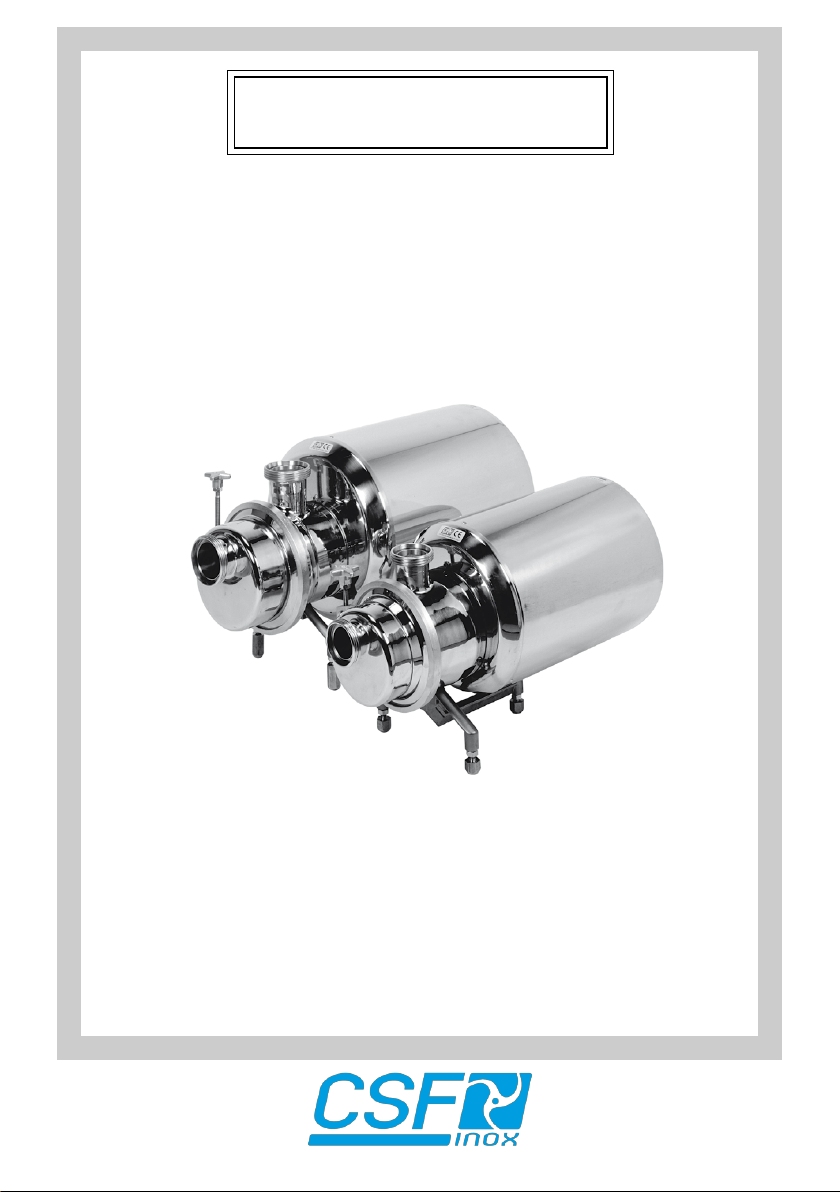
SELF-PRIMING PUMPS
AS Series
INSTRUCTIONS FOR INSTALLATION,
OPERATION AND MAINTENANCE
Page 2

pag. 2
Page 3
pag. 3
"Translation of the original instructions"
INDEX
FOREWORD
1 SYMBOLS
2 SAFETY WARNINGS
3 GUARANTEE
4 GOODS TRANSPORTATION, RECEIVING AND TRANSFERRING
4.1 Transportation
4.2 Receiving
4.3 Transferring
5 DESCRIPTION
5.1 Setups
6 SOUND PRESSURE LEVEL
7 INSTALLATION
7.1 Suction and inow conditions
7.2 Piping
7.3 Electrical connection
8 NON-PERMITTED USES
9 OPERATION
9.1 Preliminary operations and starting
9.2 Operating checks
9.3 Working irregularities
10 EXTENDED STOP
10.1 Cleaning the pump
10.2 Disposal of the pump
11 SPARE PARTS
12 SEALS
13 MAINTENANCE
13.1 Disassembly of AS pump ''T'' exec.
13.2 Disassembly of AS pump ''Q'' exec.
14 BEARING MAINTENANCE
14.1 Bearings maintenance for AS series pumps
14.2 Bearings maintenance for AS series pumps with housing size 160 - 180
15 CLEANING PROCEDURE
Version: 08 Date: 10/03/16
Page 4

pag. 4
Page 5
pag. 5
FOREWORD
- Read the instructions carefully and keep them for future consultation.
- C.S.F. Inox S.p.A. reserves the right to make any changes to the documentation it deems necessary without being obliged to update publications that have already been issued.
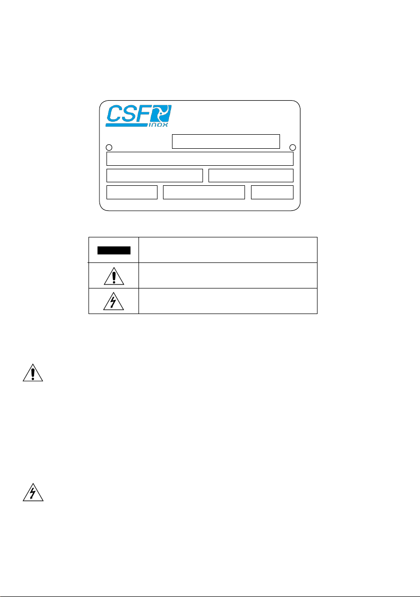
- When requesting information, spare parts or assistance, always specify the pump type (*) and
serial number (**) in order to ensure fast and efcient service: the complete code is given on the
plate and in the purchase documents.
1 SYMBOLS
Item.
Mod. AS 65-4-7,5/B.PT31 (*)
N° 12345 (**)
kW 5,5
Volt 380-660 Hz 50
Giri 1400
Plate example
2 SAFETY WARNINGS
WARNING
Pay great attention to the text parts indicated by this
symbol.
Danger: the non-observance of instructions can cause
serious damages to persons and/or objects.
Danger: only skilled personnel is allowed to carry out
operations concerning the electric parts.
When the pump is working the following occurs:
- Electric parts are in tension.
- Mechanical parts are moving.
- Pump body, pipelines and articulations are under internal pressure. Therefore do not remove any
protection or locking, do not loosen screws or clampings, as this can cause serious damages to
persons or objects. The clamp joining the pump casing and the cover must be well tightened and it
should not be easily unscrewed by hand. The tightening of the clamp must be carried out by means
of a key and NOT by hand.
- Non-observance of inspection and maintenance can cause damages to persons and objects,
especially when dangerous or toxic liquids are pumped.
- When pumping liquids at a temperature over 60° C, adequate protection and warning signals are
required.
- When you buy a pump with bare shaft, motor coupling operations have to be carried out according
to technical directions and law, providing adequate protections for joints, gear belts, etc.
- Operations on the electric parts have to be carried out by skilled personnel, according to technical
directions and law, on authorisation of the responsible installer.
- Installation must ensure an adequate ventilation, in order to cool the engine, as well as enough
space for maintenance operations.
Before carrying out any operation which requires to disassemble the pump (inspection, cleaning,
seal replacement, etc.), the following preliminary operations have to be carried out:
- switch off engine tension and disinsert electric connection;
- close valves on suction and outlet pipelines, in order to avoid the risk of inundation;
- use adequate protections for hands and face, if the pump contains liquids which are injurious to
health (for example acids, solvents, etc.);
- consider if the liquid which ows out of the pump when disassembling is dangerous and arrange
for adequate safety measures.
Page 6
pag. 6
3 GUARANTEE
All products manufactured by C.S.F. Inox are guaranteed to the purchaser, for one year from the
date of purchase, against hidden defects in materials or manufacture, providing that they are installed
and used according to instructions and recommendations of the manufacturer. Excluded from the
guarantee other than distinctive wear and tear are repaires to damage caused by improper use,
abrasion, corrosion, negligence, defect of installation, non-observance of inspection and maintenance,
use of non-genuine spare parts, cause of accident or fortuity and from any action carried out by the
purchaser not according to the normal instructions of the manufacturer.
WARNING Before returning to C.S.F. Inox S.p.A. any item to be substituted or repaired under
guarantee, inform about the problem the Customer Assistance Ofce and follow instructions of the
manufacturer.
Any item must be properly packed in order to avoid damages during the transfering and a technical
report explaining the fault occured, must accompany the returned item/s.
Any item with a presumed fault should be returned to C.S.F. Inox S.p.A. with shipment costs at
purchaser's charge, unless different agreements are given.
C.S.F. Inox S.p.A. will examine, repair and/or replace the returned piece and then send it back to
the purchaser on ex-works basis. Should the piece be found under warranty, no further costs will be
debit the purchaser. If, on the contrary, the fault is not found under warranty, all necessary reparations
and replacements will be charged at normal cost to the purchaser. Commercial parts incorporated
in C.S.F. products are guaranteed by their corresponding manufacturers.
4 GOODS TRANSPORTATION, RECEIVING AND TRANSFERRING
4.1 TRANSPORTATION
The packings of all pumps manufactured by C.S.F. Inox - S.p.A. are dened when making the order.
Unless prior arrangements are given, goods will be packed only for transit conditions and not for
long-term storage; in case it should be necessary to store the pumps outside, you are requested
to cover the pumps appropriately in order to protect the electrical parts (motor) from rain, dust,
humidity etc.
4.2 RECEIVING
WARNING By goods receiving, the wholeness of packing must be veried, in order to identify possible
damages to the content occured during transfering and to claim them immediately to the carrier.
Should any damage be ascertained, the following procedure must be observed:
- collect the goods with reservation;
- take the necessary pictures showing the damages;
- notify the suffered damages, by registered airmail, to the carrier by sending at the same time the
pictures taken to show the damaged pieces.
4.3 TRANSFERRING
Carry the packed pumps as close as possible to the place of installation by means of appropriate lifting
devices and unpack them. During this operation take care, as unsteady parts could fall down.
The material used for packing (wood, paper, cellophane, etc.) should be properly got rid,
according to the corresponding rules in force in receiver’ s country.
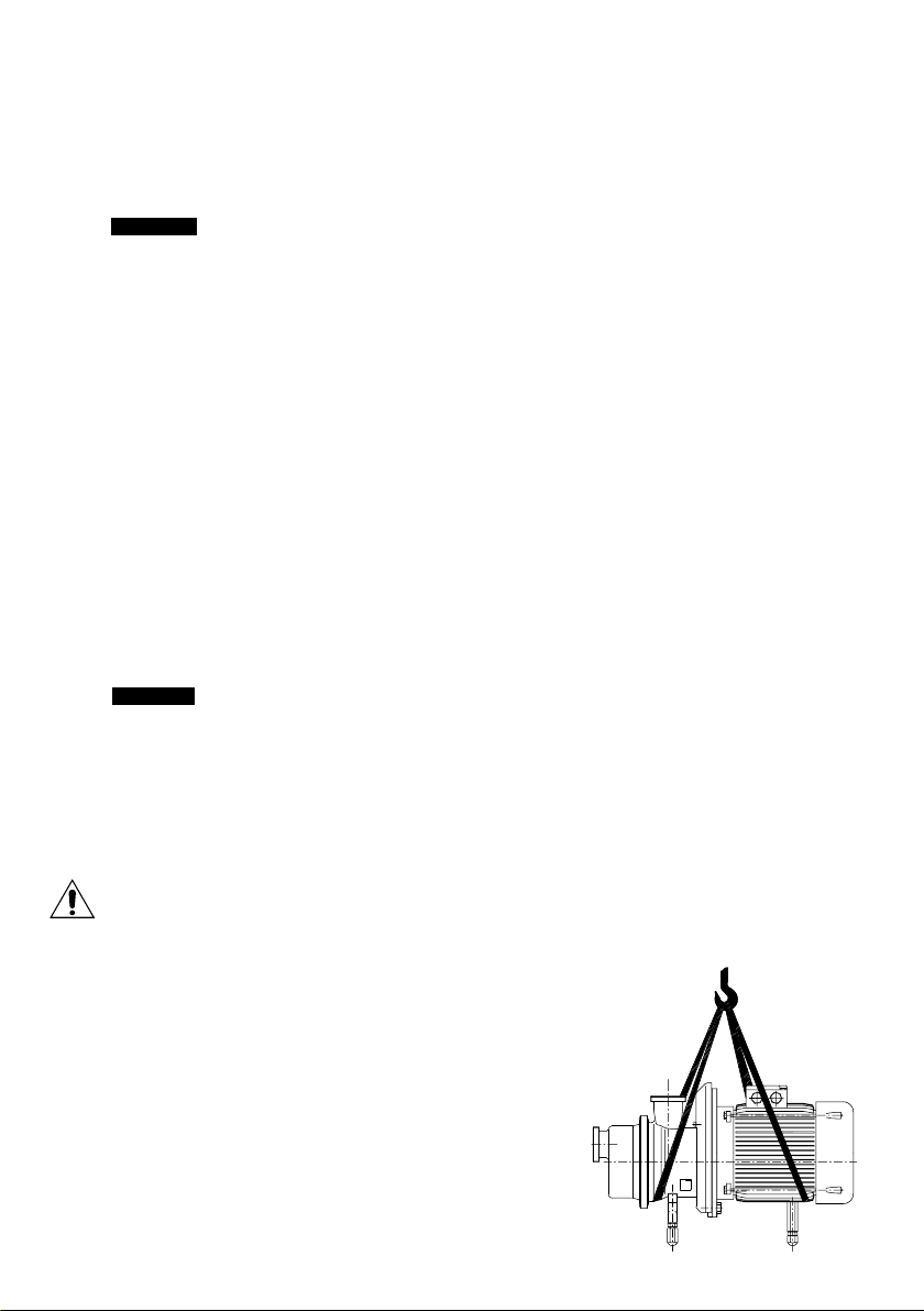
After unpacking the pump, use special lifting belts and
move the pump-motor-set to the place of installation;
never use the eyebolts on the motor to move the pump,
as the eyebolts are for moving the motor only.
In versions complete with shroud, take the shroud
off before moving the pump-motor-set, in order to
avoid damages.
Page 7
pag. 7
5 DESCRIPTION
The pumps of serie AS are centrifugal side channel self-priming with star-shaped impeller; the
ports are located on the longitudinal axe with the suction located on the front of the pump cover. All
models have threaded connections for ttings according to DIN 11851 standard (unless otherwise
requested). The pump front cover is easy to open to improve cleaning and inspection operations; all
models are tted with mechanical seals and the materials used for the components of mechanical
seal are chosen according to the liquid to be pumped.
Designed in close-coupled version, tted with indipendent standard electric motors B5 shape, IP 55
protection (unless otherwise requested).
These pumps are designed for applications where the liquid to be pumped :
- is not subject to pollution of any kind,
- is at a temperature between -20°C and +100°C,
- must under no circumstances come into contact with the outside environment,
- is chemically aggressive.
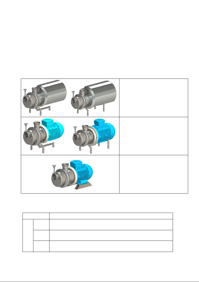
5.1 SETUPS
(1) AS - exec. with shroud with
adjustable feet kW 1,1 to kW 4
(2) AS - exec. with shroud with
(1)
adjustable feet kW 5,5 to kW 22
(2)
(1) AS - exec. without shroud with
adjustable feet kW 1,1 to kW 4
(2) AS - exec. without shroud with
adjustable feet kW 5,5 to kW 22
(1)
(2)
AS - exec. without shroud with
xed feet
kW 1,1 ÷ 22
6 SOUND PRESSURE LEVEL
The sound pressure level of self-priming pumps is the following (see table):
Pump type
< 80
81÷85
level dB(A)
86÷90
Sound pressure
AS 40
AS 42 AS 50
AS 52 AS 60 AS 65 AS 80
The measurement has been made by means of a phon-meter placed at 1 m distance from the pump
and at a height of 1.6 m from the ground.
Preliminary condition is that the pump is xed correctly; the above mentioned values do not take
into account external noise sources (e.g. valves, abrupt hydraulic deections).
Page 8
pag. 8
7 INSTALLATION
7.1 SUCTION AND INFLOW CONDITIONS
(NPSH = Net Positive Suction Head)
NPSH of system (available NPSH)
In order to ensure that pump operation is free from cavitation, it is essential to observe the maximum
permitted suction lift ha geo max or the minimum allowable head hc geo min.
NPSH of pump (required NPSH)
The centrifugal pumps can operate correctly only if vapour has not formed inside. For this reason
the static head at the reference point for the NPSH is the centre of the impeller, that is the point of
intersection of the pump shaft axis with the vertical plane that passes through the external points
of the blade inlet corners.
NPSHnec. is the value required by the pump, expressed in metres, obtained from the performance
curve. In practice 0.5 m should be added to this value as a safety margin.
7.2 PIPING
In order to prevent the creation of harmful stresses, the suction and discharge pipes must be connected to the pump ports without the use of force. These pipes must also be supported independently
avoiding causing stresses on the pump. The internal diameter must be the same size as the pump
connections. It must in any case not be smaller to avoid head loss and/or poor performances. Always
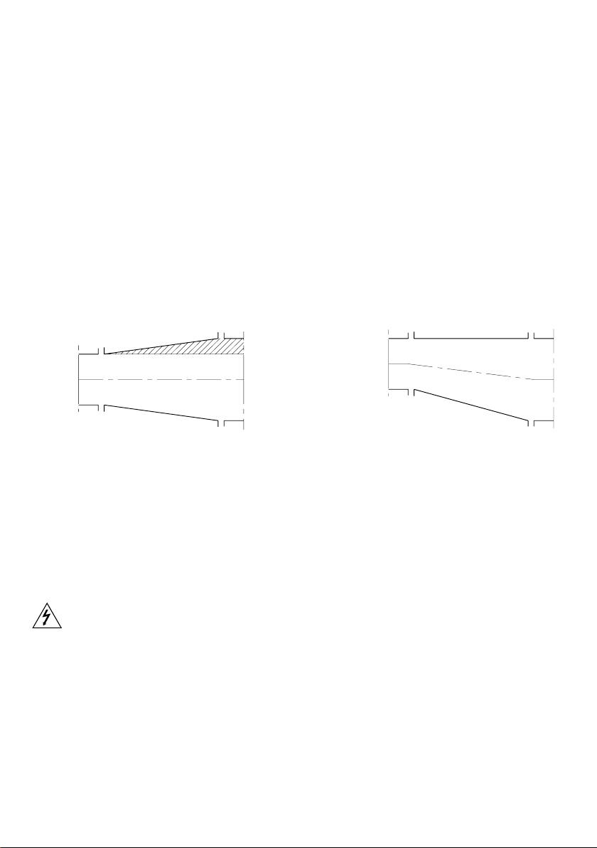
use elbows with large radius. If the pipe diameter changes along the line, use reduction cones,
choosing the ones that are most suitable for avoiding the formation of air pockets (Pict. 1).
NO
YES
Pict. 1
The suction pipe must be as short as possible and rise as it moves towards the pump if it is sucking
from a tank, if on the other hand the pump is below the level of the liquid, the pipe should descend
slightly. If the pump is used for transporting hot liquids, t expansion joints to compensate any
expansion of the piping. The maximum velocity of the liquid in the suction pipe must not be greater
than 3 m/s. Velocities between 1 and 2 m/s are recommended.
The suction pipe must be designed in such a way as to prevent air from entering the pump. For
this reason, when sucking from a tank located at a lower level, the pipe must reach below the free
surface of the liquid. Avoid creating obstacles which could increase suction losses disrupting smooth
uid ow. Make sure that there are no restrictions, sharp turns or tight elbows on the discharge line,
since these increase disturbance near the pump.
7.3 ELECTRICAL CONNECTION
Make the electrical connection only after the hydraulic connection has been completed; set up the
motor control system in conformity with the technical standards and regulations in force (EN 60204-
1): in particular a manual electric power switch must be installed with adequate current switching
capacity; devices for overcurrent and overload protection (e.g. fuses, automatic switches, etc.) must
also be tted, plus, if necessary, a device to prevent accidental restarting.
Check that the main frequency and voltage and the available power are suitable for the motor
installed. All the material used for the electrical connection (cables, cable clamps, switches and
shielding) must have a suitable level of protection for the environment in which it is installed. Be sure
to use cables of sufcient cross-section for the current shown on the motor plate so as to prevent
them from overheating. Before doing anything else, make the motor's earth connection, using the
terminal on the motor and a cable of sufcient cross-section. The cables may be connected to the
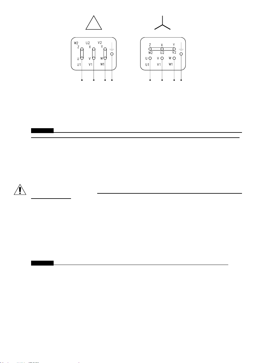
terminal board using either a delta or star arrangement. Follow the data given on the motor plate
for the main voltage, as shown in the diagram in pict.2; ensure that the terminals are clean and tight
and not under stress.
When starting, the motor's current absorption increases briey to 5-6 times the nominal value. If the
mains supply is unable to sustain this increase in absorption, use a star-delta starter or other kind
of device (e.g. an autotransformer).
Page 9
pag. 9
Lower
voltage
Higher
voltage
Pict.2
C.S.F. Inox S.p.A. will accept no responsibility for damage to property and/or injury to persons caused
by failure to comply with technical standards and regulations in force.
8 NON-PERMITTED USES
Do not use the pump with a suction pressure greater than the specied value (0.5 times the discharge
head generated by the pump).
The pump must always be used in an environment appropriate to the level of protection of the motor.
Always check this on the motor plate before installation.
WARNING THE PUMP MAY NOT BE USED IN ENVIRONMENTS WHICH REQUIRE A HIGHER
LEVEL OF PROTECTION OR A HIGHER SPECIFICATION MOTOR OR ELECTRICAL PARTS.
Components complying with the safety standards for the environment in question must be used.
9 OPERATION
9.1 PRELIMINARY OPERATIONS AND STARTING
When rst starting, ll the pump with liquid so as to create the pressure drop required for suction.
When starting subsequently the quantity of liquid that remains in the pump will be sufcient to ensure
self-priming even if the pipe is empty. Make sure that the pump does not become completely empty
in the event of installation under a vacuum or to a siphon. If necessary, t a check valve.
- Check that the pump turns freely under hand pressure.
- Check that the clamp joining the pump casing and the cover is well tightened and that it cannot
be easily unscrewed by hand. The tightening of the clamp must be carried out by means of a key
and NOT by hand.
- Check that the pump turns in the market direction.
- Check that any gate valves installed on the suction and discharge pipelines are open.
- Start the pump and check the turns direction; before restarting it is extremely important to wait until
the pump has stopped moving completely.
9.2 OPERATING CHECKS
- If the pump does not generate the required discharge head rapidly, facilitate priming by stopping
the pump and adding liquid.
- Check that the absorption of the motor does not exceed the value specied on the plate.
- The pump must always work smoothly and without vibrations.
- Do not operate without liquid and in any case avoid prolonged operation with the discarge gate valve
closed.
WARNING WITH SERIES AS PUMPS NEVER CLOSE DISCHARGE SIDE COMPLETELY.
- Mechanical seal: check that there is no leakage along the shaft.
9.3 WORKING IRREGULARITIES
The pump does not prime
- Air has entered the suction piping; check the seals on the ttings and tighten them sufciently.
- Suction pipe not submerged in liquid.
- Clearances between impeller/cover and impeller/body have increased. Check and correct.
- No liquid in the pump. Introduce liquid.
- Reduce loss of suction head; reduce the suction height.
- Formation of air pockets; eliminate and if necessary t an air unloader on discharge.
No ow
- Pump not primed; (see point 8 and previous point).
- Pump turning in wrong direction.
- Suction port obstructed.
- On-off valves closed.
Page 10
pag. 10
Insufcient ow
- Increased system back pressure on discharge side; increase piping diameter.
- Air entering mechanical seal; check its condition.
- Viscosity of uid greater than that specied in the order. Contact manufacturer.
- Clearances between impeller/cover and impeller/body have increased. Check and correct.
Loss of head
- Back pressure on discharge side has fallen; throttle the suction pipe.
- Clearances between impeller/cover and impeller/body have increased. Check and correct.
Increase in absorbed power
- Flow rate is lower than required.
- Pump is turning at higher speed.
- The impeller does not turn freely. Check it.
- Viscosity and/or specic weight are higher than stated.
- Bearings are not in good condition.
Increase in absorbed current
- The power required has increased (see previous point).
- Main voltage value has fallen.
- There is a fault in the electrical system.
10 EXTENDED STOP
When stopping the pump for a longer time, empty the pump completely and wash it accurately in
order to avoid the formation of scales and/or encrustations. When starting the pump again, please
follow the above mentioned instructions.
10.1 CLEANING THE PUMP
The pump does not require any special washing procedures. The washing cycles normally used for
the plant in which it is installed are quite satisfactory. When using the pump for liquids that tend to
harden or crystallize, always make sure it is washed before periods when the machine is to be taken
out of operation. This will ensure durability of the seal and of the pump itself.
It is the user's responsibility to ensure that the washing liquids are compatible with the process
liquid and the pump.
10.2 DISPOSAL OF THE PUMP
For disposing the pump please observe the following instructions:
- disconnect electrical and hydraulic connections according to technical rules and laws in force.
- Disassemble all components of the pump for separate dismantling; wash the components and
clean the structure accurately.
The main components of the pump are made from the following materials:
- Pump casing, cover, impeller, S.S. Aisi 316L
shaft, impeller nut
- Elastomeres NBR - EPDM - FLUOROCARBON (FPM) - TEFLON
- Motor Aluminium - Cast iron - Copper
Components made from amianthus or lead are not used in our production.
WARNING The components of the pump should be properly got rid, according to the corre-
sponding rules in force in receiver’s country.
11 SPARE PARTS
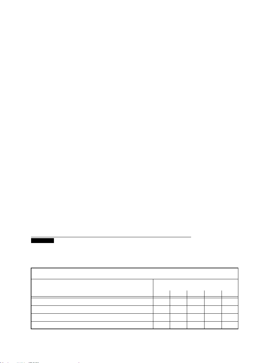
RECOMMENDED SPARE PART FOR TWO YEARS OF OPERATION
ACCORDING TO THE NUMBER OF PUMPS INSTALLED - VDMA STANDARD
Denomination
Number of pumps
(including reserve)
1 2 3 4 5
MECHANICAL SEAL
PUMP BEARING
O-RING SEAL
O-RING SEAL NUT
C.S.F. Inox declines all responsibility for damage or injury resulting from the use of non-original spare
parts
2
1
1
2
2
3
1
1
3
5
3
5
4
4
2
2
6
7
6
7
Page 11
pag. 11
12 SEALS
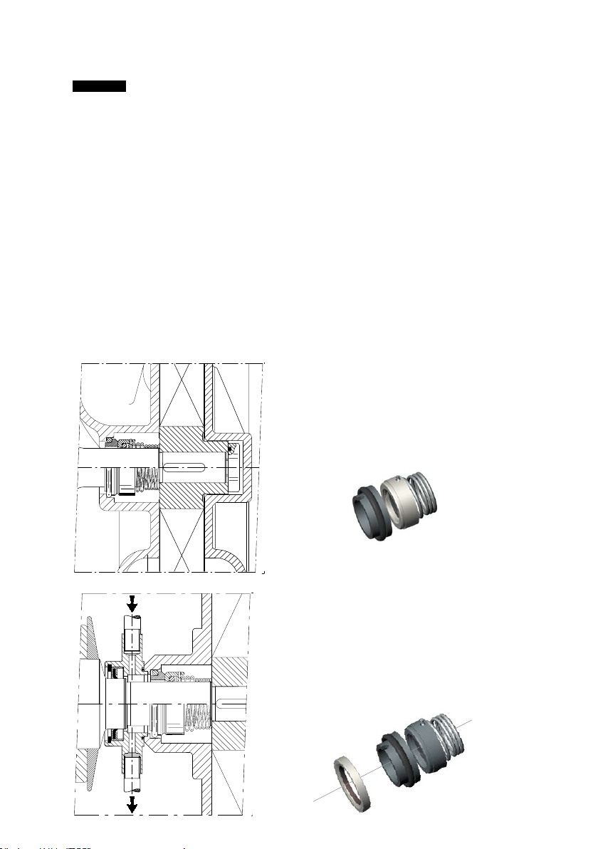
All C.S.F. centrifugal pumps of the AS series are tted with unied mechanical seals according to EN
12756 - ISO 3069 standards, in order to grant the interchangeability (subject to verication of axial space).
The type of mechanical seal and material are chosen according to the liquid to be pumped.
WARNING Before using the pump for any liquids other than those specied when selecting and
ordering, ensure that mechanical seals and gaskets are suitable for the new product.
MATERIAL CODES
METALS
X - Stainless steel AISI 316L
L - Hastelloy (Ni alloy)
METAL OXIDES
2 - Alumina ceramic
ELASTOMERS
6 - Nitrile (NBR)
7 - Ethylene propylene (EPDM)
W - FPM for high T
Y - Fluorocarbon (FPM)
B - Silicone
Q - Chemraz
U - Kalrez
CARBONS
V - Normal carbon
Z - Special carbon
RESINS
5 - Normal PTFE
4 - Loaded PTFE
F - O-RING FEP
METAL CARBONS
3 - Hard metal welded on
stainless steel (TUC)
R - Integral anti-corrosion
hard metal (TUC)
K - Integral silicate carbon (SIC)
EXECUTION T
STANDARD MECHANICAL SEAL ASSEMBLY “T”
Internal assembly seal, running into the handled
product and placed immediately behind the impeller
in a special seal chamber to ensure the correct
re-circulation around the seal faces.
EXECUTION V
INTERNAL MECHANICAL SEAL ASSEMBLY “V”
The external liquid circulation chamber prevents any
damages to the electric motor and contamination of
the environment, due to the possible leakage of the
internal mechanical seal.
Page 12
pag. 12
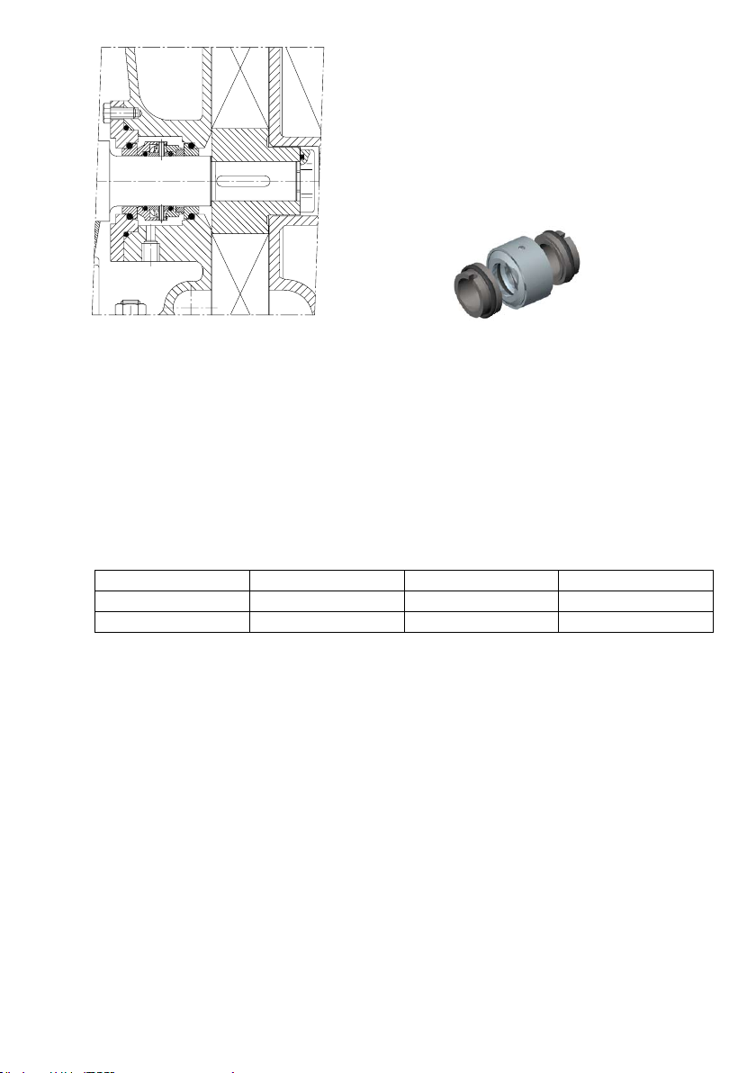
EXECUTION Q
COMPACT DOUBLE MECHANICAL SEAL ASSEMBLY
“Q”
Double back-to-back assembly seal, suitable for abrasive,
dirty, crystallizing or high-temperature liquids.
The seal assembly is completely housed and the
latter is provided with inlet/outlet ushing media that
lubricates and cools the seal faces preventing also
crystal formation. In case of product-side seal leakage,
traces of the handled product can be noted into the
ushing media.
"Q" and "V" Exec. mechanical seal auxiliary ushing
Upon the rst start up, the lling of the pump, must be guaranteed. Furthermore, you must guarantee
the full lling of the auxiliary systems, if present, such as the lubrication circuit of the external dualseal (seal execution “Q”) or the external ushing circuit (seal execution “V”).
Lack of compliance with the present requirements causes the dry operation of the pump and of the
mechanical seal; consequently the mechanical seal can be overheated and damaged.
The auxiliary services (optional) are the following:
- ushing for the double external mechanical seal (seal execution “Q”)
- external ushing for the internal seal (execution “V”).
The following conditions are recommended:
Execution Speed Capacity l/min Pressure bar
"Q" 1450-1750 0,5-1,0 See seal instructions
"V" 1450-1750 0,2-0,5 0,5
Exec."Q": in case of leaks from the process seal (pump side) the ushing liquid comes into contact
with the pump uid; always use a ushing liquid that is compatible with the process liquid.
The mixing of incompatible liquids can cause strong exothermic reactions with the development
of heat.
In the presence of dangerous liquids and /or use of ushed seals (execution “Q”-“V”) the presence
of the ushing liquid must be monitored by means of a system that can intervene to stop the pump
in case of ushing liquid absence.
In the presence of liquids dangerous to health and/or the environment, it is advisable to insert a
monitoring device of the seal ushing liquid that can intervene to stop the pump or as an alarm sign,
in case of contamination of the ushing liquid.
Operation checks
Verify the presence of ushing of the mechanical seal (execution “Q”-“V”).
Verify the absence of leaks from the auxiliary service connections of the seal (if present).
Page 13
pag. 13
13 MAINTENANCE
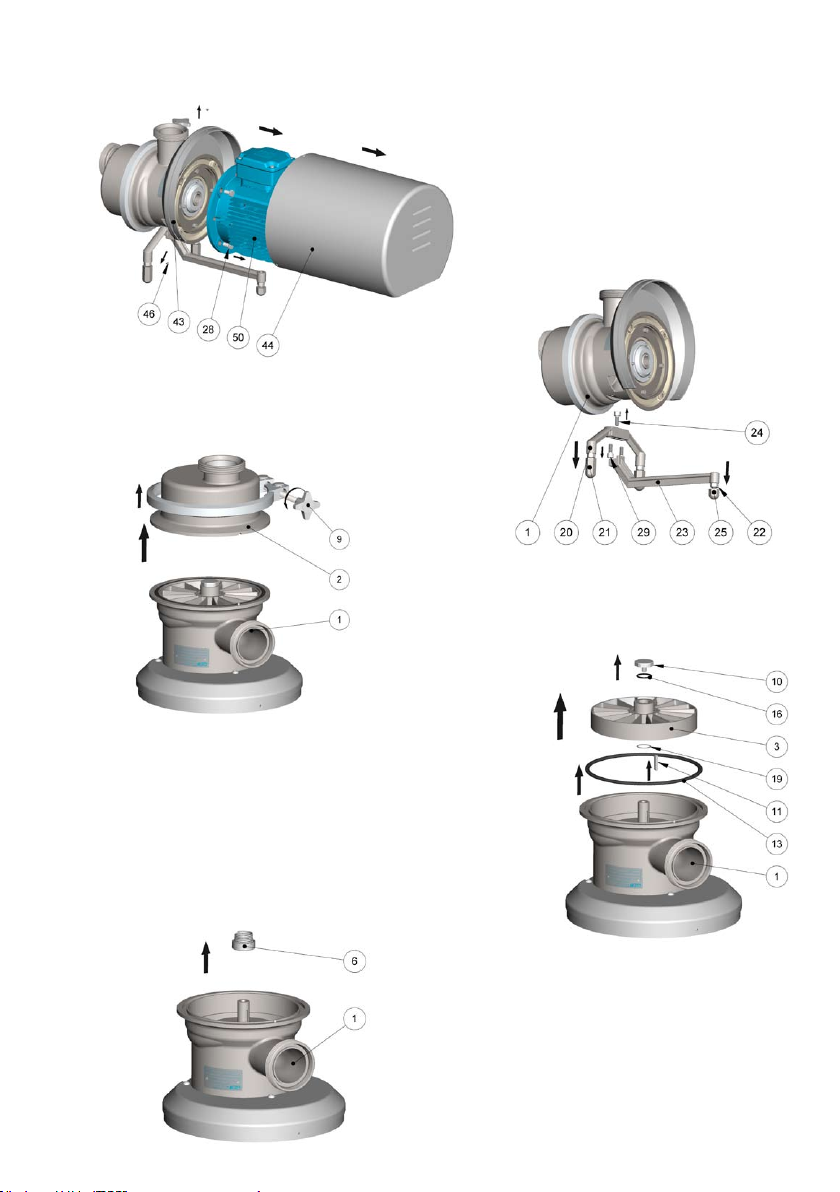
13.1 DISASSEMBLY OF AS PUMP ''T'' EXEC.
B= Disassemble the supporting
feet (20-23) with the screws
(24-29).
C= Loosen and remove the
clamp (9) to separate the cover
(2) from the pump casing (1).
A= Remove screws (46) to disassem-
ble the shroud.
Take off the screws (28) from the mo-
tor and remove it from the pump.
D= Unscrew the nut (10) with the O-ring (16) anti-clockwise;
this can be done:
1) using a pneumatic screwdriver
2) using a xed wrench blocking the shaft on the motor end.
NB:(Part. 10) hexagonal nut CH=34 mm (AS 40-50-60-65)
CH=50 mm (AS 80)
Remove the impeller (3), the key (11) from the shaft, the
shims (19) which produce the mounting clearance and the
O-ring (13) from the pump casing (1).
E= Extract the rotary part of the mechanical seal (6) turning the spring
anti-clockwise.
Page 14
pag. 14
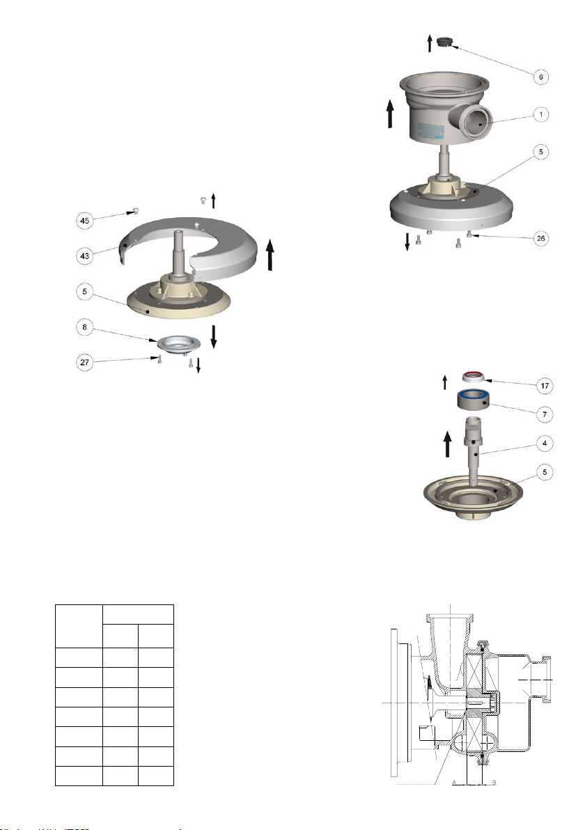
F= Turn it over to access the screws
(26) which allow you to separate the
pump casing (1) from the support (5).
Extract the xed part (6) of the seal
from the pump casing.
G= Unscrew the screws (45-27) to
remove the shroud eccentric (43)
and the bearing cover (8) from the
support (5).
H= Extract the shaft (4) - bearing (7) ring nut (17) unit from the support (5).
Unscrew the ring nut (17) and extract the
bearing (7) from the shaft (4).
RE-ASSEMBLY
The pump is assembled by proceeding with the steps in the opposite direction.
REFERENCE TABLE FOR ASSEMBLY ALLOWANCE
Pump
AS 40 0,15 0,15
AS 50 0,15 0,15
Dimensions
A B
A = Impeller/pump casing
assembly allowance
(implemented with shims
pos. 19
)
B = Impeller/cover assembly allowance
AS 60 0,2 0,2
AS 65 0,2 0,2
AS 80 0,3 0,3
AS 42 0,15 0,15
AS 52 0,15 0,15
Shims
Page 15
pag. 15
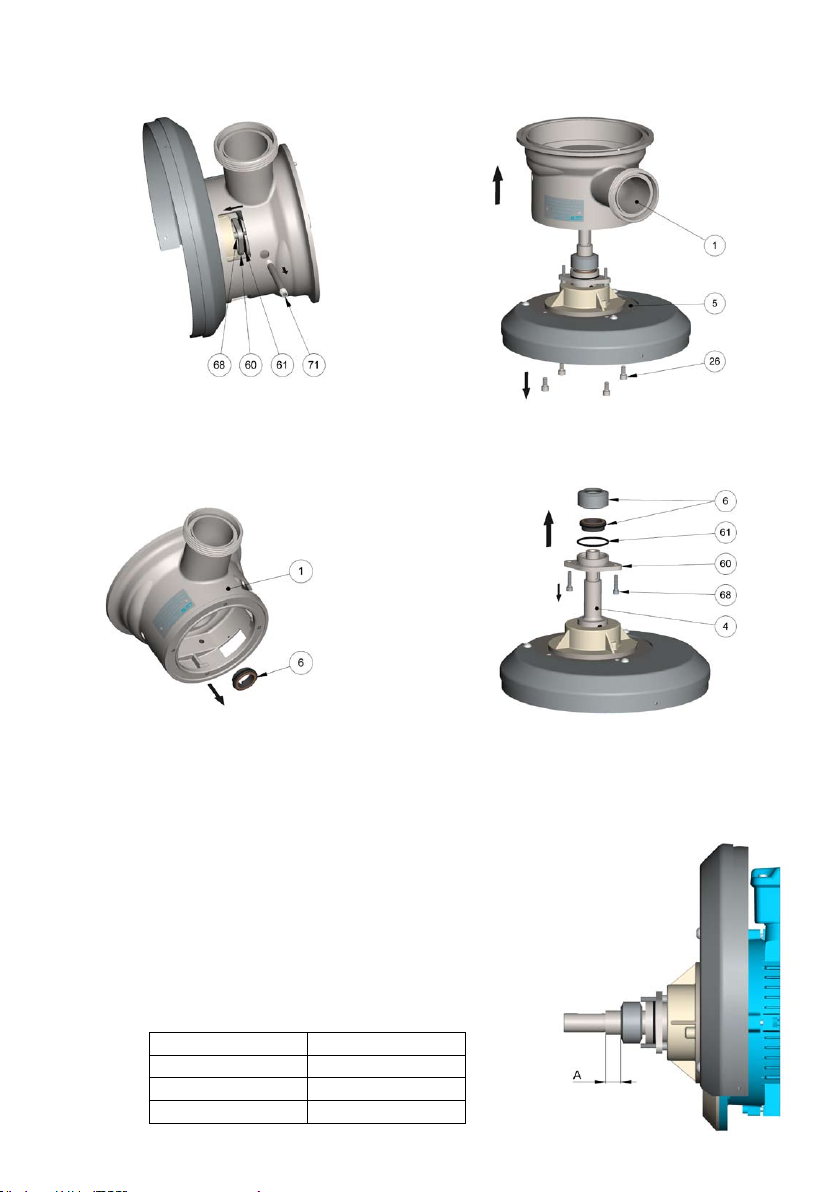
13.2 DISASSEMBLY OF AS PUMP ''Q'' EXEC.
Refer to the "T" exec. (paragraph 13.1) for the A-B-C-D phases
E= Pump casing disassembly (1).
Unscrew the flushin g pipes (71), remove the screws (68) and pull back the mecha nical
seal cover (60). Extract the support/ pump casing (26) fixi ng screws and separate them
(1-5).
F= Mechanical seal disassembly (6).
Remove the internal fixed part of the seal (6) from the pump casing and the rotating
part (6) from the shaft (4), after having loosened the fixing dowels.
By removing the cover (60) with the O-ring (61) from the shaft, it is possible to remove
the external fixed part (6) of the seal (6) from the same.
"Q" Exec. ASSEMBLY
The pu mp is as sembled by proceedi ng wi th the steps
in opposite direction.
IMPORTANT: the positioning of the seal's (6) rotating
part must respect the "A" dimension.
Dimension "A"
AS 40-42 16
AS 50-52 17,5
AS 60-65 15,5
AS 80 19,5
Page 16
pag. 16
14 BEARINGS MAINTENANCE
14.1 BEARINGS MAINTENANCE FOR AS SERIES PUMPS
In AS series pumps up to motor size 132 (5.5 ÷ 9.2 kW) the bearings installed are shielded and
consequently do not need to be lubricated.
14.2 BEARINGS MAINTENANCE FOR AS SERIES PUMPS WITH HOUSING SIZE 160 - 180
The bearings of AS pumps are sized for an operational life of 20,000 hours or more.
The life of the bearing and feasible re-lubrication interval may be reduced in the following cases:
harsh working conditions (high ambient temperature and humidity, dust, aggressive atmosphere),
use with frequent starting and stopping cycles and/or at variable loads and extended periods of
inactivity.
Maintenance intervals are therefore to be established according to the conditions of use and based on acquired experience.
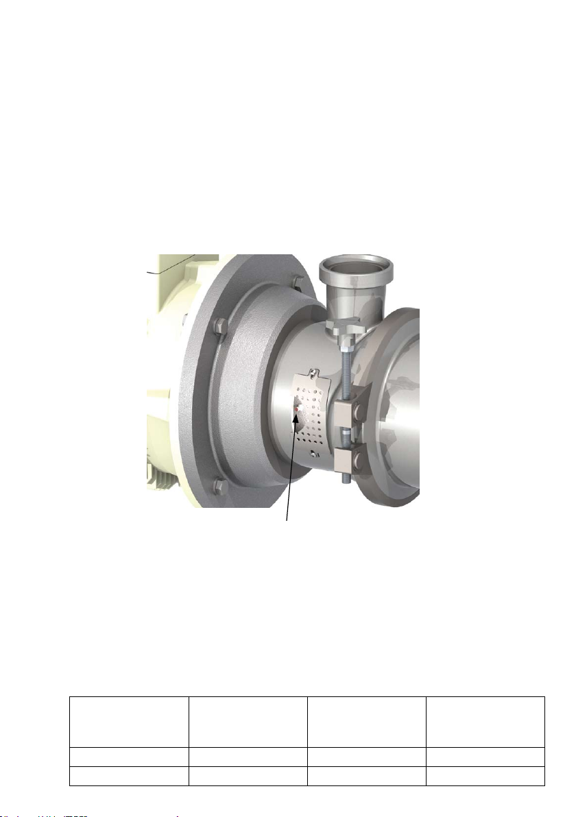
“AS” series pumps
(Pict. 1)
Grease nipple
In AS series pumps with housing size 160 - 180, the bearings must be lubricated periodically; to
ensure correct lubrication, the bearing must be disassembled, cleaned thoroughly and lubricated
with fresh grease, making sure only to ll the crowns to half their volume. They can be topped-up
with grease periodically via the grease nipple on the bearing housing (see pict. 1).
Each time the bearing is disassembled, replace the grease lip sealing gasket (pos. 33), making
sure the ring sealing seat is not worn.
To lubricate the bearings correctly, you are recommended to use high performance grease
of SKF LGHP2 with temperature range -30°C/150°C.
The following table provides indications on the re-lubrication interval on the amount of grease
recommended and the type of bearing on the pump.
Lubrication
Pump AS Bearings
interval
(hours of operation)
of grease
(grams)
Motor IEC 160 3212 A C3 5000 20
Motor IEC 180 3214 A C3 5000 20
Q.ty
Page 17
pag. 17
15 CLEANING PROCEDURE
The cleaning of stainless steel pumps depends on the process liquid.
Typically the cleaning process should be developed by a plant responsible of sanitization.
C.S.F. Inox recommends a uid velocity between 1,5-3 m/s, with rinsing water and chemical agent
like alkaline detergent and acid.
Chemicals like hypochlorite and chlorine must be avoided because stainless steel could be damaged
by corrosion.
Alkaline detergent:
A sodium hydroxide/water solution may be used at concentration 1-3% at a temperature of 70-90°C;
a surfactant could be added to increase the rinse cleaning.
Acid solution:
It is used to neutralize alkaline residual and for the passivation of the stainless steel surface; a
solution of nitric acid at 1-2,5% could be used at ambient temperature up to 45°C.
Other acid solution could be: citric acid and water (0,5-3% at 70°C) and phosphoric acid at 0,5%
with a temperature up to 45°C (with inhibitor of corrosion).
Suggested cleaning process:
1) Prerinse with cold water (15-25°C) for 10-15 minutes to remove any residue.
2) Warm prerinse with water at 45-60°C for 10 minutes.
3) Rinse with alkaline solution at 70-95°C for 20-30 minutes.
4) Intermediate rinse with water (warm or cold) up to 60°C for 5-10 minutes.
5) Rinse with acid solution like nitric acid for 10 – 15 minutes at ambient temperature.
6) Final rinse with cold water for 10-15 minutes or until any traces of cleaning agent have been
removed.
Caution:
1) During the CIP process there are thermal expansion: take care that there are not rapid tempe-
rature variation.
2) Chemical agents at high temperature can cause potential health risk: respect the safety regulation
and use protection devices
3) Control the concentrations and temperature of chemical agents during the CIP.
4) Store the cleaning agents in compliance with the safety regulations
Sterilization:
If requested, a sterilization can be carried out by means of hot water or steam; the pump must be
stopped during the sterilization process with steam. See the admissible temperature for sterilization
depending on gasket compound.
Temperature limits for rubber gasket Steam/hot water Chemical bactericidal
EPDM 121°C 82°C
FPM/FKM 149°C 82°C
Impeller nut cleaning and sterilization:
1) The dismantled nut should be cleaned before assembling (internal threads).
2) Clean the nut with Ultrasound washing system or detergent and rinsing with clean water.
3) Sterilize the nut with steam at 143°C for 30 mintes in autoclave or using chemicals solution (i.e.
glutaraldheyde solution). Do not use chlorine solutions because satainles steel could be damaged
by corrosion.
Page 18

Page 19

Page 20
Distributed in the UK by.....
Pump Engineering Limited. Unit B1, Riverside Industrial Estate,
Littlehampton, West Sussex, BN17 5DF, United Kingdom
Tel: 01903 730900 - Fax 01903 730234
email: [email protected] Web: www.pumpeng.co.uk
All the instructions, data and representations (in whatever way executed) listed in this publication are indicative and do not binding. C.S.F. does not stand surety or undertake any obligation for the utilisation of this document and for the information contained. In particular, it does not guarantee against omissions or errors of the data and drawings here indicated.
Notice that the technical specications, information and representations in this document are merely indicative and approximate.C.S.F. INOX reserves the right at any moment and
without notice to modify the data, drawings and information indicated in this document.. C.S.F. INOX guarantees its own products according to the general guarantee conditions in
compliance with the required modes of utilisations as per separate documents, regardless of what is indicated in this document, if the assembly and operating methods of the products
are observed. Only the instructions indicated in the contract documents, if duly undersigned by authorised C.S.F. INOX personnel, are binding for C.S.F. INOX.
cod. DOCIAS lingua inglese
 Loading...