

Installation and Operating Instructions
1. Identification of company and product
Company : CSB Battery Europe B.V.
Keurmeesterstraat 28-30
2984 BA Ridderkerk
Phone : Europ : +31 180 418 140
Asia : +886 2 8751 5000
Américas : +1 817 244 7777
2. Safety Issues
Read carefully this document.
Fire hazard.
Use safety goggles.
Explosion hazard.
Corrosive hazard.
Electrical hazard.
Dispose spent batteries properly.
3. Transporting.
When transporting the battery, avoid excessive vibration and impacts.
We recommend transporting the battery in an upright position.
When transporting a battery connected to equipment, secure it firmly
and keep the circuit open.
4. Battery Receiving.
Previously the installation of the battery, check for correct shipment
quantities and transport damage.
5. Storage.
Store battery indoors in a cool (25ºC (77°F) or less), clean and dry
location.
During storage, the capacity of the battery decreases due to selfdischarging.
Supplementary charging has to be carried out according to Table 1.
Table 1 : Storage temperature and recommended supplementary
charge interval.
When using a stored battery, always carry out supplementary charge
before use according to Table 2.
Storage
temperature
in °C (°F)
Lower than
25°C (77°F)
25 - 30°C
(77 - 86°F)
Recommended
supplementary
charge interval
Each 6 months
Each 3 months
Supplementary
charging methods
16 to 24 hours with
a constant voltage of
2.275 V/cell
5 to 8 hours with a
constant voltage of
2.45 V/cell
Product : AGM VRLA Battery
Absorbant Glass Ma terial
Valve Regulated Lead-Acid
Ranges : GP, GPL, HC, HR, HRL and XHRL.
Table 2 : Supplementary charge characteristics.
Charge Method
Constant Voltage
Charging at
2.45V/Cell
Constant Current
Charging at
0.05CA
Charge time
in h
6-12 5-35
6-12 5-35
Ambient
temperature
in °C (°F)
6. Installation and connection.
• Secure the battery firmly to protect it from excessive vibration or
impact.
• When placing the battery in equipment, keep it away from a heat
generating source (e.g., a transformer) and install it in an upright
position with proper ventilation. The weight will be concentrated as
much as possible in the low part of the equipment.
• The battery may produce a combustible gas. Avoid installation in
closed compartment or near sparks (i.e., near a switch or fuse).
• Using vinyl chloride sheathed wire or a vinyl chloride sheet may
crack the battery container and cover. Either keep it away from the
battery or use a non-plasticizing vinyl chloride material.
• Never bend the terminal nor solder directly to it.
• Avoid using the battery in the following places:
o Areas exposed to direct sunlight
o Areas where there is excessive radioactivity, infrared radiation,
or ultraviolet radiation
o Areas filled with organic solvent, vapor, dust, or corrosive gases
o Areas of abnormal vibration
• When connecting the battery to a charger or a load, keep the
circuit switch OFF and connect the battery's positive (+) terminal to
the positive (+) pole of the charger or the load and the battery's
negative (-) terminal to the negative (-) pole of the charger or the
load.
• Never use the batteries of different capacities, batteries of different
performances, or new and old batteries together.
• Do not series connect more than 32 pieces of battery in a single
string or parallel connect more than 4 strings. If more batteries are
needed for series/parallel application as stated above, please
contact CSB Technical Support.
Table 3 : Torque specifications.
Screw/Bolt
diameter
M5 6.4 63.4 5.73 56.7 4.14 41.0
M6 11.5 113.9 10.32 102.2 7.45 73.8
M8 28.0 272.2 25.23 249.8 18.22 180.4
Battery must be installed in accordance with EN-50272-2 standard.
Peak Min Max
N.m kg.m N.m kg.m N.m kg.m
Torque value
7. Charging.
Constant voltage charging method is recommended to charge our
battery. This method consists of applying constant voltage to the
battery with a constant voltage unit. This charging method utilizes a
Monday, August 10 200 9 1/2 TD20090810 – V03
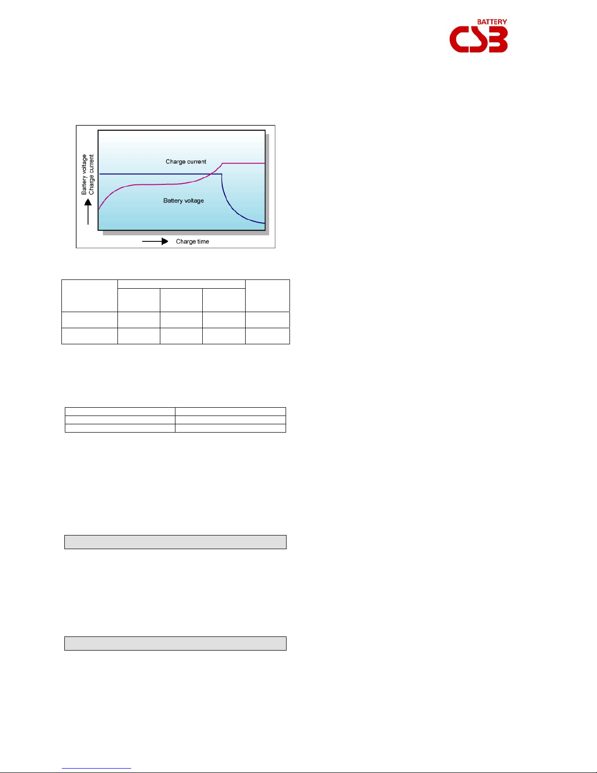
different voltage between its voltage and battery voltage. The
charging current is initially large and decreases towards the end of
charging. It is necessary to set the charging voltage according to
battery charging and temperature characteristics. Inaccurate voltage
causes an overcharge or an undercharge.
Graph 1 : Constant Voltage Characteristics.
Initial charging current should be 0.3CA or less, min 0.1CA.
Table 4 : Charge voltage and maximum charge current.
Applications
Cycle service
Standby
Temperature compensation is not necessary when the battery is
charged at an ambient temperature between 5°C (41°F) to 35°C
(95°F), with average temperature below 25°C (77°F). At temperatures
below 5°C (41°F) or above 35°C (95°F), temperature compensation
for charging voltage is necessary.
Table 5 : Temperature coefficient.
Applications Temperature coefficient
Cycle service -5mV/ºC/cell
Standby -3.3mV/ºC/cell
When batteries are used in serial, a single current is imposed on all
the cells. However, if the voltages begin to differ, the result is a
charge imbalance. To restore balance or at least prevent it from
growing, equalization charging is required. Equalization charging
characteristics are a constant voltage of 2.45 V/cell for 5 to 8 hours.
More sophisticated charging methods are available : constantcurrent, constant-voltage charging method, semi-constant current
charging method, constant current charging method, multi-steps
charging method, high frequency pulse charging method. Please
contact CSB Technical Support for more details.
Charging voltage in V/Cell
Temp.
in °C (°F)
25ºC
(77ºF)
25ºC
(77ºF)
Set point
2.45
2.275
Allowable
range
2.40 ~ 2.50
2.25 ~ 2.30
Max
charging
current
in A
0.3CA
0.3CA
8. Discharging.
• The continuous discharge and maximum discharge current (for 5
Seconds) should never exceed the values shown in Product
Specifications.
• Never discharge the battery until the voltage and current are less
than the values shown in Product Specifications. Repeated over
discharge will shorten the battery's life.
• After discharging, immediately recharge the battery. Never leave it
discharged. The capacity to hold a charge may not be recovered if
the battery is left discharged for a long period.
9. Periodic Inspections & Maintenance.
For optimum reliability, it is recommended that the battery system be
monitored quarterly. If the battery system incorporates an automatic
monitoring system to gather the electrical and environmental data,
the quarterly checks are limited to the evaluation of the recorded data
and a visual inspection of the battery.
In general the types of inspections to be made during periodic
maintenance include :
• Visual battery inspection,
• Battery system capacity test,
• Battery system voltage inspection,
• Ambient temperature,
• Individual battery float voltage inspection,
• High rate load test,
• Electrical resistance and tightness of inter-unit connections.
A test of the individual unit resistance, impedance or
while optional, is also recommended on a periodic basis. This data
and its trends can be a valuable aid in troubleshooting the system
and predicting the need for a system capacity test.
Prior to starting the periodic maintenance activity assure that all the
required maintenance tools and equipment is available and
functional. Notify anyone who will be affected by the intended
maintenance or troubleshooting activity.
All units in the battery should be numbered so as to facilitate the
recording and analysis of data unique to each unit.
conductance,
9.1 Quarterly VRLA Battery Inspection
• Assure the battery room is clean, free of debris and with proper
lighting.
• Assure that all facility safety equipment is available and functional.
• Measure and record the air temperature within the battery room.
• Visually inspect the battery for :
o Cleanliness,
o Terminal damage or evidence of heating,
o Container or cover damage.
• Measure the DC voltage from each polarity of the battery to
ground and detect any ground faults.
• Measure and record the individual unit DC float charging voltage,
and current.
• Measure and record the system equalization voltage, and current.
• Measure and record the temperature of the battery cabinet
inspections.
9.1 Semiannual VRLA Battery Inspection
• Repeat the quarterly inspection.
• Randomly measure and record the resistance/conductance of the
individual units to trend the condition of the individual units over
time and to detect dramatic differences between individual units
and the average.
9.3 Annual VRLA Battery Inspection
• Repeat the semiannual inspection
• Re-torque all of the inter-unit connecting hardware. This can be
omitted if the connection resistance is measured and found to
have not increased more than 20% from the value recorded at
installation
Monday, August 10 200 9 2/2 TD20090810 – V03
 Loading...