

CS TrackSystems, WallMountTrack, FH-CeilingMountTrack, PartionTopMountTrack Installation Instructions Manual
Page 1
WHAT YOU NEED TO KNOW FIRST.
Contamination of the top track.
It is essential when installing CS TrackSystems
that all dust, swar f or contamination is removed
from the inside of the track before fitting your
door.
Ensure tracks are securely and adequately fixed
to the framing/lintel on site and are running level
to guarantee a smooth running door.
Follow the preparation instructions below, then
turn to page 3 and follow the relevant track
installation instructions.
PREPARATION.
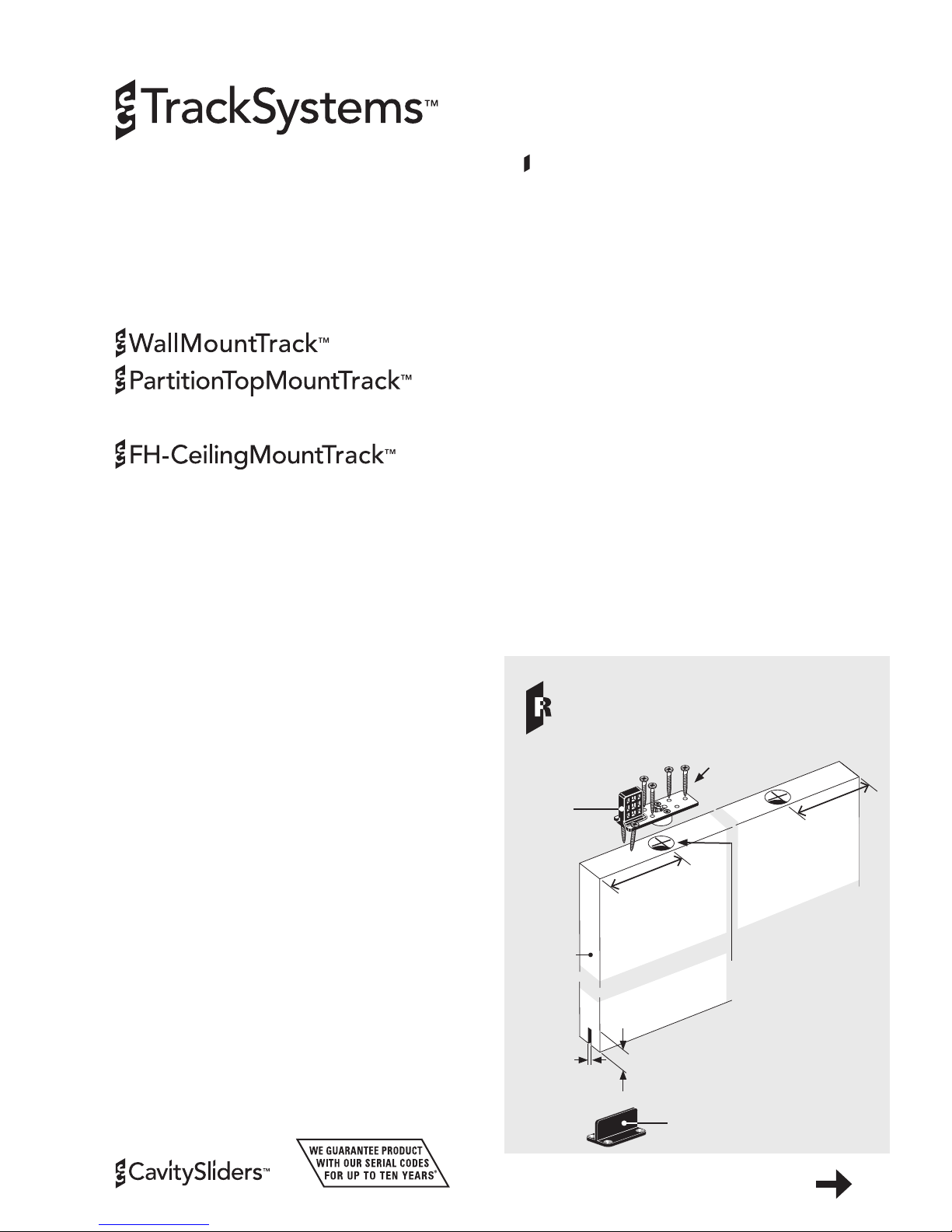
1 Fit the mounting plates (drawing R).
Drill front and rear holes 125mm in from the
edge of the top of your door leaf as shown
(drawing R).
Note: these mounting plates must be placed
exactly in the centre of the door thickness.
At the bottom of each door leaf, cut a groove to
the dimension and tolerance shown.
Make it central to the door thickness and
absolutely straight.
Screw the mounting plates to the doors, making
sure the black plastic stop is facing the edge of
the door.
sliding door track.
or
1
2
PAGE
PAGE
Before you start:
Edge of
door leaf
© CS Cavity Sliders Pty Ltd.
125mm to
centre of the
boss hole
Fit the 6
screws as
shown
125mm
Black
plastic
stop
Drill ø25mm (1”)
x 13mm deep.
Face of
door leaf
T-Guide
PREPARING THE DOORS
See point 1.
20-21mm
5-5.5mm
Go to page 3 (overleaf)
© CS Cavity Sliders Pty. Ltd. CS TRACKSYSTEMS™ (O.D. 2008). 60396/AU / ZNI070 - 02.2018
Check out the full range of products and use
our on-line calculator at: www.cavitysliders.com.au
Installation
Instructions
READ these
CAREFULLY !
Installation
Instructions
Another quality product from:
Page 2
4
PAGE
NOW FOR THE INSTALLATION ITSELF.
2 Fix the track:
Go to instruction 3, page 4
Go to instruction
3, page 4
Go to instruction
3, page 4
Go to page
5 (overleaf)
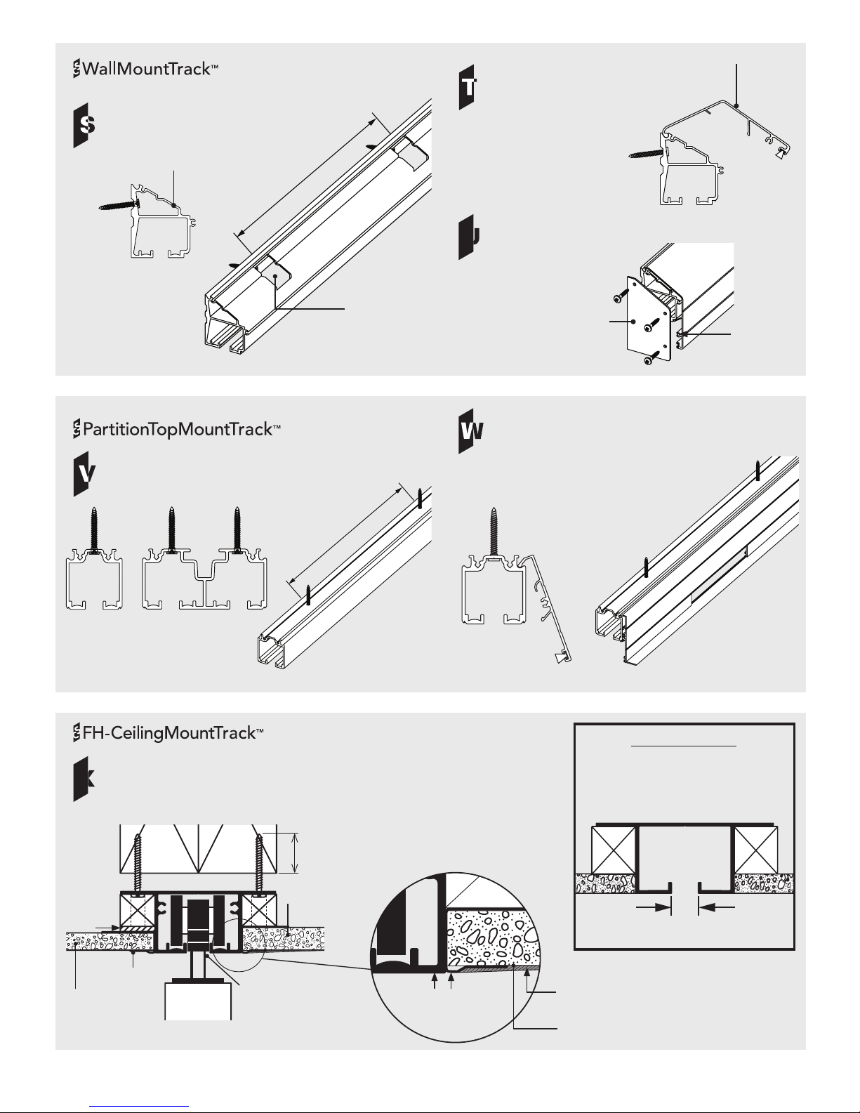
CS WallMountTrack is screw fixed from the side
through the pre-machined slots in the extrusion
(drawing S). Hole centres are pre-set at 300mm
apart.
Screw fix the track to the stud wall using 8 gauge
screws, ensuring it is level and solid enough to
suppor t the door weight.
For fixing to concrete walls, the use of masonry
anchors is recommended. You may need to open
the existing holes to suit the type of masonr y
anchor you have selected.
Clean out all swarf and debris from the track
before hanging the door.
CS PartitionTopMountTrack is screw fixed
through the recessed section in the top of the
track. Hole centres are pre-set at 300mm apart.
Single Track
Screw fix the track to the ceiling/framework
through the recessed section in the top of the
track using 8 gauge screws (drawing V).
Ensure the track is level and solid enough to
suppor t the door weight.
Clean out all swarf and debris from the track
before hanging the door.
Double Track
Follow the same procedure as above, however
two screws are required side by side (one in each
track section).
CS FH-CeilingMountTrack comes with 3mm
packers attached to the bottom of the pelmet
blocks (drawing X). These packers should be lef t
in place if 10mm plaster board is used.
For 13mm plaster board, remove the packers to
allow the bottom of the plaster board to sit flush
with track.
Tracks are supplied with pre-drilled fixing holes.
Fit J-mould (not supplied) along opening of
doorway. Cut lining in and fix. Ensure underside
of track is level with the underside of the
J-Mould. This may require the underside of the
track to finish 1-2mm below the underside of the
ceiling before stopping.
Plaster and finish, taking care to keep the inside
of the track free of dust and paint splatter by
opening the door(s) fully and masking the track
slot(s).
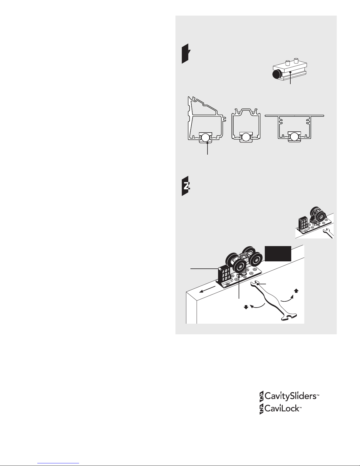
3 Fit the door(s) (drawing Y and Z, overleaf).
Remove the track stops from the track (if already
fitted) (drawing Y) by loosening the two stainless
steel cap screws with an Allen key and sliding the
stops until they drop out of the notched /open end
of the track.
Load the carriages into the track from the
notched end. Position the door underneath the
carriages and of fer the mounting plate onto the
wheel hanger shaft.
Depress the plunger using the bolt head and
slide across until the bolt snaps into locked
position.
Screw the black plastic floor guide in the correct
location. The T-Guide should be concealed
directly below the front edge of the door.
Note: a 50mm high T-Guide is available if
required.
Once doors are installed and running smoothly,
insert the track stops into the track and tighten
in the correct location (drawing Y).
4 Adjust the door height (drawing Z, page 6).
Use the small end of the spanner supplied to
rotate the hexagonal nut at the bottom of the
carriage hanger.
To raise door: Rotate spanner from lef t to right.
To lower door: Rotate spanner from right to left.
Note: The hanger shaft fits into a self-locking nut.
If you turn the hexagonal nut too far downwards,
the shaf t will become loose from the self-locking
nut. If the turning resistance suddenly feels much
easier, you have gone too far.
Longer hanger pins are available if more height
adjustment is required.
Note (FH-CeilingMountTrack): When winding
up the door you may find that the hanger bolt
rubs on the track. If this occurs it is okay to
remove the wheel from the track and cut down
the bolt to create the extra clearance required.
Take care not to damage the start of the hanger
thread when shortening the bolt.
5 Attach the pelmet & end caps (if required)
CS WallMountTrack (drawing T & U)
Remove protective tape from pelmet if applied.
Insert top leg of pelmet (A) into the recessed
groove at the top of the track extrusion
(drawing T).
Push down firmly until middle leg (B) clips
into groove (C) along the bottom of the track
extrusion.
Screw end caps into screw tubes inside track
and pelmet extrusions as shown (drawing U)
using screws provided.
CS PartitionTopMountTrack (drawing W).
Remove protective tape from pelmet if applied.
Insert top leg of pelmet (A) into the recessed
groove at the top of the track extrusion
(drawing W).
Push down firmly until middle leg (B) clips
into groove (C) along the bottom of the track
extrusion.
Adjustment of door can be made through the
access slot (D).
(drawing S)
A
B
C
(drawing V)
(drawing X)
Page 3
300
© CS Cavity Sliders Pty Ltd.. Drawings are not to scale. A ll dime nsion s in mm.
300
A
B
C
FIXING THE TRACK
See point 2A.
FIXING THE TRACK
See point 2C.
FIXING END CAPS
See point 5.
AT TACHING PELMET
See point 5.
Pelmet
End cap
Screw tube
Tra c k
extrusion
Pre-machined
slots
300
300
100
A
B
D
C
Legged Pelmet
FIXING THE TRACK
See point 2B.
AT TACHING PELMET See point 5.
Single
Tra c k
Double
Tra c k
Flush Pelmet
U
300
Plaster as required
Underside of track
and J-Mould should
finish at same level
Door
J-Mould
Hanger bolt
3mm
MDF
packer
13mm lining
10mm lining
25mm
IMPORTANT
Original track slot width must be
maintained when lining ceiling.
Smooth running may otherwise
be affected.
DO NOT PINCH!
!
Underside of
ceiling
X
Page 4
5
PAGE
© CS Cavity Sliders Pty Ltd.
ADJUSTING & REMOVING
CARRIAGES
See points 3, 4 & 6.
M6
Carriage
M8
Carriage
6 Removing the door(s) (drawing Z).
Using the spanner supplied, slide the extended
end down the threaded part of the hanger shaf t
of the carriage.
Fit it over the hexagonal nut at the bottom.
Use the extended part of the spanner to press
down the curved release pin that points up from
the mounting plate.
Once this pin is fully depressed, you can slide
the spanner sideways in the direction of that pin.
The whole carriage including the shaf t will come
loose from the mounting plate.
It is not always easy to slide the spanner
sideways. You could relieve the weight of the
door by put ting a thin wedge between door and
floor.
Do the same with the second carriage.
Remove the black plastic stop that is tightly
fitted into the mounting plate by tapping it out in
the direction shown using a hammer and drift.
(drawing Z).
You can remove the doors now (for painting,
repairs etc).
If you want to take the carriages out: Remove the
track stops from the track (if fitted) (drawing Y) by
loosening the two stainless steel cap screws with
an Allen key and sliding the stops until they drop
out of the notched /open end of the track.
6
PAGE
Y
TRACK STOPS
See point 3 & 6.
PartitionTopMountTrack
FH-CeilingMo u n tTrack
WallMountTrack
Tra c k s top
Tra c k s top
CS Cavity Sliders Pty Ltd
PO Box 158
Freshwater, NSW 2096
T 02 9905 0588
F 02 9905 7088
[email protected]
www.cavitysliders.com.au
All copyright and other property in this document is reserved by CS Cavity
Sliders Pty. Ltd. Details and specifications are subject to change without
notice. Whilst all care is taken to ensure the accuracy of all information, no
responsibility will be accepted for any errors or omissions.
*Guarantee conditions apply. Contact CS Cavity Sliders Pty. Ltd. for details.
Australian Patent: 2005 202818.
To lower
door
To raise
door
Adjusting
spanner
Plunger
pin
Club end
of spanner
Black plastic
stop
Tap this way to
remove
WARNING
See po int 15
 Loading...