

Page 1
INSTRUCTION MANUAL
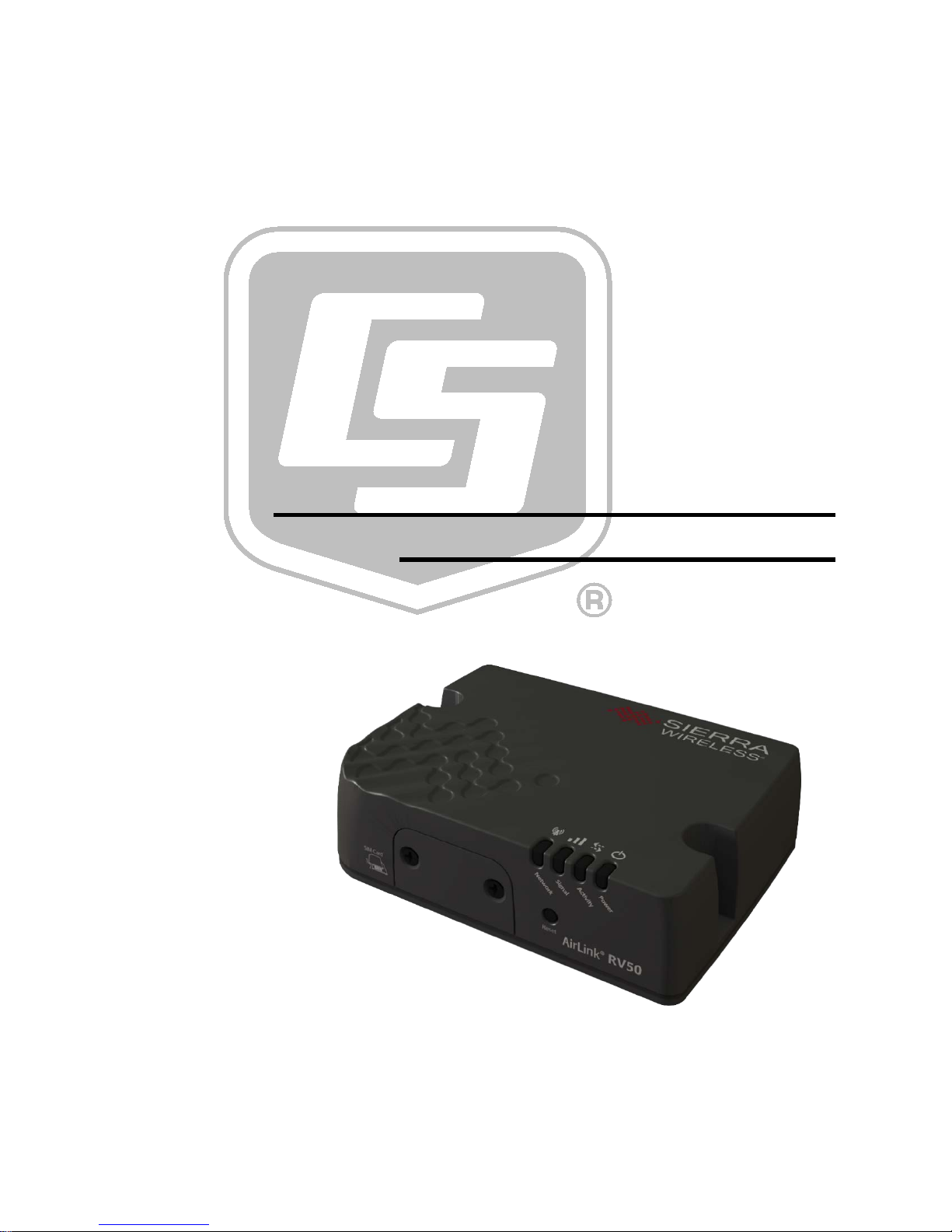
RV50 Sierra Wireless AirLink®
Copyright © 2016
Campbell Scientific, Inc.
4G LTE Cellular Modem
Revision: 6/16
Page 2

Page 3

Limited Warranty
“Products manufactured by CSI are warranted by CSI to be free from defects in
materials and workmanship under normal use and service for twelve months
from the date of shipment unless otherwise specified in the corresponding
product manual. (Product manuals are available for review online at
www.campbellsci.com.) Products not manufactured by CSI, but that are resold
by CSI, are warranted only to the limits extended by the original manufacturer.
Batteries, fine-wire thermocou p les, desiccant, and other consumables have no
warranty. CSI’s obligation un der this warranty is limited to rep a iring or
replacing (at CSI’s option) defective Products, which shall be the sole and
exclusive remedy under this warranty. The Customer assumes all costs of
removing, reinstalling, and shipping defective Products to CSI. CSI will retur n
such Products by surface carrier prepaid within the continental United States of
America. To all other locatio ns, CSI will return such Products be st wa y CIP
(port of entry) per Incoterms ® 2010. This warranty shall not apply to any
Products which have been subjected to modification, misuse, neglect, improper
service, accidents of nature, or shipping damage. This warranty is in lieu of all
other warranties, expressed or implied. The warranty for installation services
performed by CSI such as programming to customer specifications, electrical
connections to Products manufactured by CSI, and Product specific training, is
part of CSI's product warranty. CSI EXPRESSLY DISCLAIMS AND
EXCLUDES ANY IMPLIED WARRANTIES OF MERCHANTABI LI TY
OR FITNESS FOR A PARTICULAR PURPOSE. CSI here by disclaims,
to the fullest extent al lowed by applicable law, any and all warranti e s and
conditions with respect to the Products, whether express, implied or
statutory, other than those expressly provided here in.”
Page 4

Assistance
Products may not be re t urned without prior authorization. The followi ng
contact information is for US and international customers residing in countries
served by Campbell Scientific , Inc. directly. Affiliate companies handle repairs
for customers within their territories. Please visit www.campbellsci.com to
determine which Campbell Scie ntific company serves your countr y.
To obtain a Returned Materials Authorization (RMA), contact CAMPB ELL
SCIENTIFIC, INC., phone (435) 227-9000. After an application engineer
determines the nature of the problem, an RMA number will be issued. Please
write this number clearly on the outside of the shipping container. Campbell
Scientific’s shipping address is:
CAMPBELL SCIENTIFIC, INC.
RMA#_____
815 West 1800 North
Logan, Utah 84321-1784
For all returns, the customer must fill out a “Statement of Product Cleanliness
and Decontamination” form and comply with the requirements s pecified in it.
The form is available from our website at www.campbellsci.com/repair. A
completed form must be either emailed to [email protected] or faxed to
(435) 227-9106. Campbell Scientific is unable to process any returns until we
receive this form. If the form is not received within three days of product
receipt or is incomplete, the product will be returned to the customer at the
customer’s expense. Campbell Scientific reserves the right to refuse service on
products that were exposed to contaminants that may cause health or safety
concerns for our employees.
Page 5

Safety
DANGER — MANY HAZARD S ARE ASSOCIATED WITH INSTALLING, USING, MAI N T AINING, AN D W ORKING ON OR AROUND
TRIPODS, TOWERS, AND ANY ATTACHMENTS TO TRIPODS AND TOWERS SUCH AS SENSORS, CROSSARMS, ENCLOSURES,
ANTENNAS, ETC. FAILURE TO PROPERLY AND COMPLETELY ASSEMBLE, INSTALL, OPERATE, USE, AND MAINTAIN TRIPODS,
TOWERS, AND ATTACHMENTS, AND FAILUR E TO HEED WARNINGS, INCREASES THE RISK OF DEATH, ACCIDENT, SERIOUS
INJURY, PROPERTY DAMAGE, AND PRODUCT FAILURE. TAKE ALL REASONABLE PRECAUTIONS TO AVOID THESE HAZARDS.
CHECK WITH YOUR ORGANIZATION'S SAFETY COORDINATOR (OR POLICY) FOR PROCEDURES AND REQUIRED PROTECTIVE
EQUIPMENT PRIOR TO PERFORMING ANY WORK.
Use tripods, towers, and attachments to tripods and towers only for purposes for which they are designed. Do not exceed design limits.
Be familiar and comply with all instructions provided in product manua ls. M an uals are av ailable at www.campbellsci.com or by
telephoning (435) 227-9000 (USA). You are responsible for conformance with governing codes and regulations, including s afety
regulations, and the integrity and location of structures or land to which towers, tripods, and any attachments are attached. Installation
sites should be evaluated and approved by a qualified engineer. If questions or concerns a rise regarding installation, use, or
maintenance of tripods, towers, attachments, or electrical connections, consult with a licensed and qualified engineer or electrician.
General
• Prior to performing site or installation work, obtain required approvals and permits. Comply
with all governing structure-height regulations, such as those of the FAA in the US A.
• Use only qualified personnel for installation, use, and maintenance of tripods and towers, and
any attachments to tripods and towers. The use of licensed and qualified contractors is highly
recommended.
• Read all applicable instructions carefully and understand procedures thoroughly before
beginning wor k.
• Wear a hardhat and eye protection, and take other appropriate safety precautions while
working on or around tripods and towers.
• Do not climb tripods or towers at any time, and prohibit climbing by other persons. Take
reasonable precautions to secure tripod and tower sites from trespassers.
• Use only manufacturer recommended parts, materials, and tools.
Utility and Electrical
• You can be killed or sustain serious bodily injury if the tripod, tower, or attachments you are
installing, construct ing, using, or maintaining, or a tool, stake, or anchor, come in contact with
overhead or underground utility lines.
• Maintain a distance of at least one-and-one-half times structure height, 20 feet, or the distance
required by applicable law, whichever is greater, between over head utilit y lines and the
structure (tripod, tower, attachmen ts, or tools).
• Prior to performing site or installation work, inform all utility companie s and have all
underground utilities marked.
• Comply with all electrical codes. Electrical equipment and related grounding devices should be
installed by a licensed and qualified e le c trician.
Elevated Work and Weather
• Exercise extreme caution when performing elevate d work.
• Use appropriate equipment and safety practices.
• During installation and maintenance, keep tower and tripod sites clear of un-trained or non-
essential personnel. Take precautions to prevent elevated tools and objects from dropping.
• Do not perform any work i n inclement weather, including wind, rain, snow, lightning, etc.
Maintenance
• Periodically (at least yearly) check for wear and damage, including corrosion, stress cracks,
frayed cables, loose cable clamps, cable tightness, etc. and take necessary corrective actions.
• Periodically (at least yearly) check electrical ground connections.
WHILE EVERY ATTEMPT IS MADE TO EMBODY THE HIGHEST DEGREE OF SAFETY IN ALL CAMPBELL SCIENTIFIC PRODUCTS,
THE CUSTOMER ASSUMES ALL RISK FROM ANY INJURY RESULTING FROM IMPROPER INSTALLATION, USE, OR
MAINTENANCE OF TRIPODS, TOWERS, OR ATTACHMENTS TO TRIPODS AND TOWERS SUCH AS SENSORS, CROSSARMS,
ENCLOSURES, ANTENNAS, ETC.
Page 6

Page 7

Table of Contents
PDF viewers: These page numbers refer to the printed version of this document. Use the
PDF reader bookmarks tab for links to specific sections.
1. Introduction ................................................................ 1
2. Precautions ................................................................ 1
3. Initial Inspection ......................................................... 1
4. QuickStart ................................................................... 2
4.1 Establish Cellular Service .................................................................... 2
4.1.1 Verizon Wireless ........................................................................... 2
4.1.2 AT&T ........................................................................................... 3
4.2 Install the SIM Card ............................................................................. 3
4.3 Configure RV50 ................................................................................... 4
4.4 Set up LoggerNet ................................................................................. 6
4.5 Set Up Hardware .................................................................................. 8
4.6 Test the Connection ............................................................................. 8
5. Overview ..................................................................... 9
6. Specifications ............................................................. 9
6.1 RV50 Specifications ............................................................................ 9
7. Installation ................................................................ 10
7.1 Base Station Requirements for RV50 ................................................ 10
7.2 Datalogger Site Equipment ................................................................ 11
7.3 RV50 Mounting Kit (pn 32252) ......................................................... 14
7.3.1 Mounting the RV50 Flat on the Backplate ................................. 14
7.3.2 Mounting the RV50 on Edge to t he Backplate ........................... 15
7.4 Wiring and Connections ..................................................................... 15
7.4.1 Modem Communication Connections ........................................ 16
7.4.2 Modem Power Connections ........................................................ 17
7.4.3 Antenna Connection .................................................................... 17
7.5 ACEmanager and Template Files ...................................................... 18
7.6 Enabling PPP Mode ........................................................................... 20
8. Operation .................................................................. 22
8.1 Ports ................................................................................................... 22
8.2 LED Indicator Lights ......................................................................... 22
8.3 Rebooting the RV50........................................................................... 23
8.4 Reset the RV50 to Factory Default Se ttings ...................................... 23
9. Attributions ............................................................... 24
i
Page 8

Table of Contents
Appendices
A. Controlling Power to t he RV50 .............................. A-1
B. EmailSend Using the Gmail™ Outgoing SMTP
Server.................................................................... B-1
B.1 Setting up a Gmail Account ............................................................ B-1
B.2 Sending to Multiple Addresses ........................................................ B-2
B.3 Sending a Text Message to a Phone ................................................ B-2
B.4 EmailSe nd Program Ex ample ......................................................... B-2
C. Configuring the RV50 for Dynamic IP ................... C-1
D. Using the RV50 Ethernet Port ............................... D-1
E. Regulator y Inform a t ion .......................................... E-1
E.1 Important Information for North American Users............................ E-1
E.2 RF Exposure ..................................................................................... E-1
E.3 EU .................................................................................................... E-2
E.4 Declaration of Conformity ................................................................ E-2
E.5 RoHS Compliance ............................................................................ E-3
Figures
4-1. SIM Card Installation .......................................................................... 4
7-1. Antennas for Use with the RV 50 Modem ......................................... 13
7-2. RV50 Mounting Options ................................................................... 14
7-3. Flat Mou nt ......................................................................................... 15
7-4. Edge Mount ....................................................................................... 15
7-5. RS-232 Connection ........................................................................... 16
7-6. CR6 RS-232 Connection ................................................................... 16
7-7. Ethernet Connectio n .......................................................................... 16
7-8. CS I/O Connecti on ............................................................................ 16
7-9. Ante nna Co n nec tio n .......................................................................... 17
C-1. Serial Server Mode with Dynamic IP .............................................. C-3
Tables
4-1. Te mplate Files ..................................................................................... 6
7-1. Power Connecti ons ............................................................................ 17
7-2. AceManager Template Files ............................................................. 19
8-1. LED Indicato r Lights......................................................................... 22
CRBasic Examples
A-1. Using TimeIsBetwee n to Turn On and Off SW12 .......................... A-1
A-2. Using If Statements to Turn On and Off SW12 .............................. A-2
B-1. Using EmailSend to Send a Text Message ...................................... B-2
ii
Page 9

RV50 Sierra Wireless AirLink® 4G LTE
Cellular Modem
1. Introduction
This manual provides information for interfacing the RV50 Sierra Wireless
AirLink® 4G LTE Cellular Mod e m to Ca mp bell Scientific dataloggers.
The RV50 d igital ce llular modem is manufactured by Sierra Wireless® and
supports network operator switching based on the SIM for use on GSM (Global
System for Mobile Communicatio ns) a nd CDMA (Code Division Multiple
Access) networks. The modem is accessed through the Internet using TCP/IP
communications protocol.
Use of the RV50 requires a Verizon® CDMA/1xRTT/EVDO/LTE or AT&T®
GSM/GPRS/EDGE/HSPA+/LTE busines s account or an equivalent account
from another service provider. See Section 4.1, Establish Cellular Service
for more information.
For additional information on the RV50 modem, see the Support section of the
Sierra Wireless website.
Before usi ng the RV50, pl ease study:
• Section 2, Precautions
• Section 3, Initial Inspection
• Section 4, QuickStart
(p. 2),
(p. 2)
(p. 1)
(p. 2)
2. Precautions
• READ AND UNDERSTAND the Safety section at t he fro nt of this
manual.
• CAUTION: This device uses considerably more power than the datalogger
(see Section 6, Specifications
switching power with the datalogger, or a combination of these to ensure
the battery is not drained. See Appendix A, Controlling Power to the RV50
(p. A-1), for program examples of using switched 12V to control power to
the RV50.
3. Initial Inspection
• The RV50 ships with the following items:
o (1) grey power cable (from original manufacturer)
o (4) screws and washers (from or igi nal manufacture r )
o (1) 2 ft Ethernet ca ble
o (1) Quick Deploy Guide
o (1) ResourceDVD
(p. 9)) and may require a larger power supply,
1
Page 10

RV50 Sierra Wireless AirLink® 4G LTE Cellular Modem
NOTE
• Upon receipt of the RV50, inspect the package and contents for damage.
File any damage claims with the shipping company.
• Immediately check package contents against the shipping documentation.
Contact Campbell Scientific ab out any discrepancies.
4. QuickStart
4.1 Establish Cellular Service
The RV50 supports network operator switching based on the inserted SIM
(subscriber identity module). This means that the same modem can be
configured for either Verizon Wireless® (CDMA), AT & T® (GSM) or other
supported CDMA and GSM networks.
4.1.1 Verizon Wireless
What you need:
• Verizon Wireless CDMA/1xRTT/EVDO/LTE coverage at the
datalogger site. For a coverage map, refer to:
www.verizonwireless.com/landingpages/better-matters/#maps
• CDMA/1xRTT/EVDO/LTE static unrestricted IP account established
with Verizon Wireless.
Generally, there is a $500 one-time-per-customer charge to
activate static IP on the account. Additional static IP lines of
service may be added at no additional charge from that time on.
To set up an account, you will need the IMEI number of the modem. The IMEI
number is listed on a label on the modem and also on the box. To set up an
account with Verizon Wireless, call:
888-384-1775 for Business Sales
800-256-4646 for Personal Sales
Verizon Wireless will provide a SIM card for each modem. The mini-SIM
(2FF) card must be installed inside of the modem as described in Section 4.2,
Install the SIM Card
• 10-digit MSISDN number (telephone number associated with the
SIM, used for billing)
• IP Address for a static IP account and an APN (Access Point Name) for
CDMA/1xRTT/EVDO/LTE service. A com mon APN used for this
application is: we01.VZWSTATIC. The user must program the APN
name into the modem as described in Section 4.3, Configure RV50
(p. 3). In addition to the SIM card, you should receive:
(p. 4).
2
Page 11

4.1.2 AT&T
RV50 Sierra Wireless AirLink® 4G LTE Cellular Modem
What you need:
• AT&T GSM/GPRS/EDGE/HSPA+/LTE coverage at the datalogger site.
For a coverage map ref er to: www.att.com/maps/wireless-coverage.html.
• GSM/GPRS/EDGE/HSPA+/LTE business account established with
AT&T
To set up a GSM/GPRS/EDGE/HSPA+/LTE business account, contact your
AT&T Business Account Representative or Blu-Telecommunications.
Blu-Telecommunications is part of the Alli a nce Cha nnel with AT&T and can
assist any customer nationwide. Blu-Telecommunications will contact AT&T
and work with an AT&T account manager to set up an account.
Contact information for Blu-Telecommunication:
Website: www.blu-tel.com
Phone number: (877) 422-2616, or Email box: [email protected]
What to ask for: M2M Setup
Who to ask for: Carlos Morales or Andy Tran
An APN must be added onto the account to make the modem accessible
through the Internet. Fo r networks with fewer than 30 modems, the standard
‘I2Gold APN’ can be used; networks with more than 30 modems will require a
‘Custom APN’. A Custom APN has a setup fee starting at $500 and takes a
minimum of 7 to 14 business days to complete. The user must program the
APN name into the modem as described in Section 4.3, Configure RV50
AT&T will provide a Subscriber Identity Module (SIM) card for each modem.
The mini-SIM (2FF) card must be installed inside of the modem as described
in Section 4.2, Install the SIM Card
should receive:
• 10-digit MSISDN number (telephone number associated with the
SIM, used for billing)
• IP Address and APN for GSM/GPRS/EDGE/HSPA+/LTE service
4.2 Install the SIM Car d
The SIM in the RV50 is a smartcard that securely stores the key identifying a
mobile subscriber. You will only need to ins ta ll the SIM once in the life of the
modem.
To install the mini-SIM (2FF) card:
(p. 4).
(p. 3). In addition to the SIM card, you
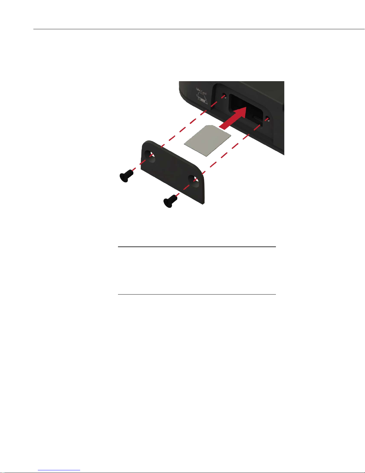
1. Remove the SIM card cover.
2. B y default, the upper slot is the primary SIM. Note the location of the
notched corner for correct alignment. The gold contact points of the SIM
face down when inserting into the upper slot as shown in FIGURE 4-1.
(They face up when inserting into the lower slot .) Gently slid e the card
3
Page 12
RV50 Sierra Wireless AirLink® 4G LTE Cellular Modem
NOTE
into the upper slot until it stops and locks into place. To eject the SIM
card, press it in slightly and release.
3. Replace the SIM card cover.
FIGURE 4-1. SIM Card Installation
4.3 Configure RV50
QuickStart describes configuring the RV50 in serial server mode.
It may also be configured in Point-to-Point Protocol (PPP) mode.
For a description of the modes, see Section
instructions on setting up the RV50 in PPP mode, see Section 7.5,
ACEmanager and Te mplate File s
PPP Mode
The RV50 is configured using ACEmanager, a web based configuration tool
hosted by the RV50. ACEmanager can be accessed using Internet Explorer® or
Firefox® remotely over the cellular WAN or locally over Ethernet. A number
of templates will be provided for download to make most configurations very
simple once connected to ACEmanager.
1. Download Campbell Scientific’s collection of RV50 configuration
templates from www.campbellsci.com/downloads and run the executable
downloaded. The templates can also be found on the Campbell Scientific
ResourceDVD.
5, Overview (p. 9). For
(p. 18), and Section 7.6, Enabling
(p. 20).
2. Connect the Cellular antenna.
3. Connect the Diversity antenna, if used. Recommended but not required.
4
Note: If a Diversity antenna is not used, use ACEmanager to disable
WAN/Celluar | Network Credentials | RX Diversity.
Page 13
RV50 Sierra Wireless AirLink® 4G LTE Cellular Modem
4. Connect the power cable leads to a power supply.
Lead Color Function Connect To
Black Ground
G
White Enable (On/Off) 12V or SW12V or control port
Red Powe r (7 to 36 V)
12V
5. Connect the power cable to the RV50 DC Power input. When the RV50 is
properly set up and powered, the status LEDs will turn on. The RV50 will
begin the activation/provisioning pr ocess and attempt to connect to the
mobile network. This process typically takes 5 to 10 minutes. A successful
connection is indicated by a solid green or solid amber Network LED. I f
the RV50 does not automatically connect to the network, you may need to
proceed to Step 6 to confirm or enter your WAN/Cellular | SIM Slot 1
Configuration | Network Credentials | User Entered APN information.
6. Co nnect your Windows® computer to the RV50 using the supplied
Ethernet cable.
7. Launch an Internet Explorer or Firefox web browser, and enter
http://192.168.13.31:9191 into the address bar. The ACEmanager login
screen should appear in your browser.
8. Log in using User Name = user and Password = 12345.
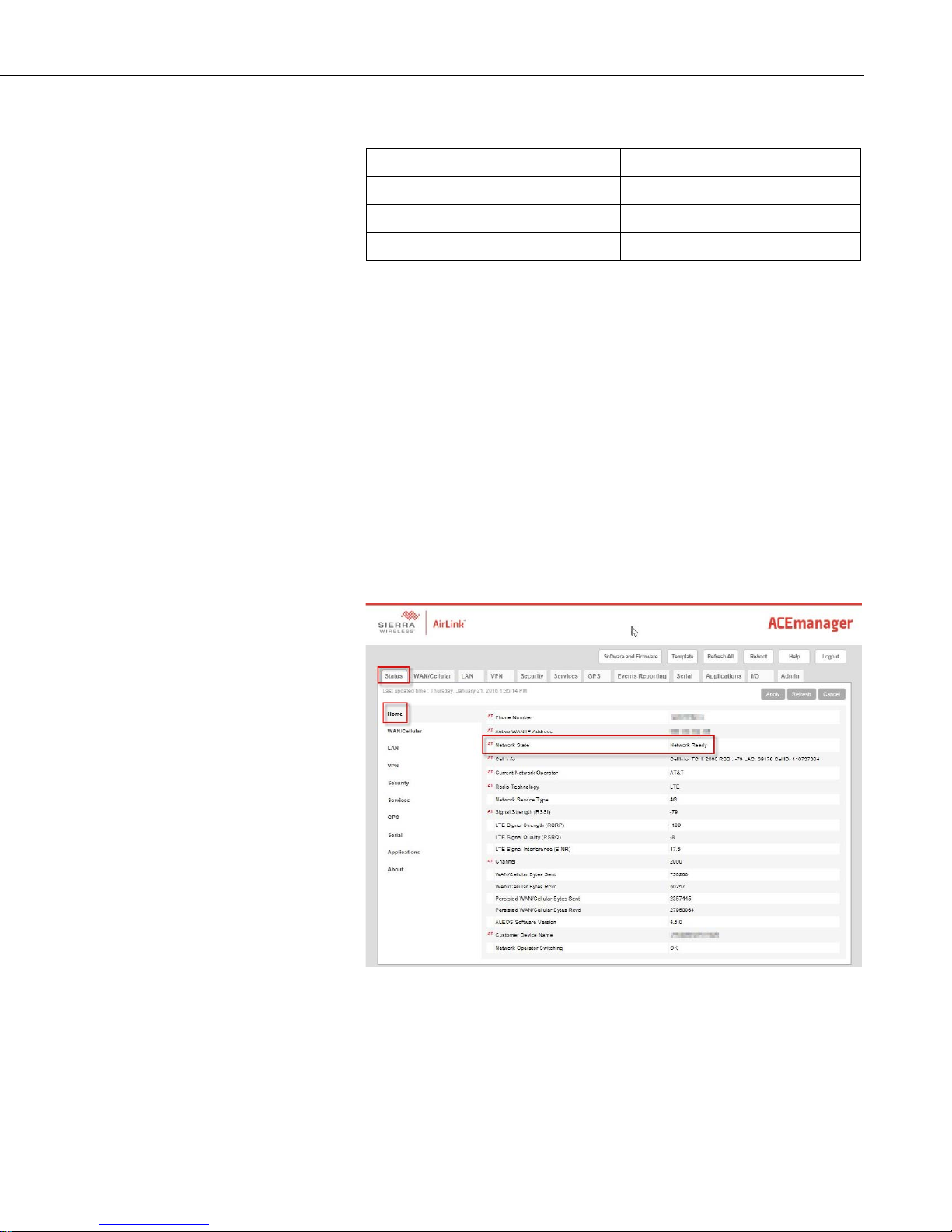
8. Once logged in, check the Status | Home | Network State field. It should
read Network Ready, indicating the RV50 is connected to the cellular
network. You can easily test the RV50 connection to the Internet by
selecting the Admin | Advanced tab and using the PING tool to ping an
Internet server, such as www.campbellsci.com.
5
Page 14
RV50 Sierra Wireless AirLink® 4G LTE Cellular Modem
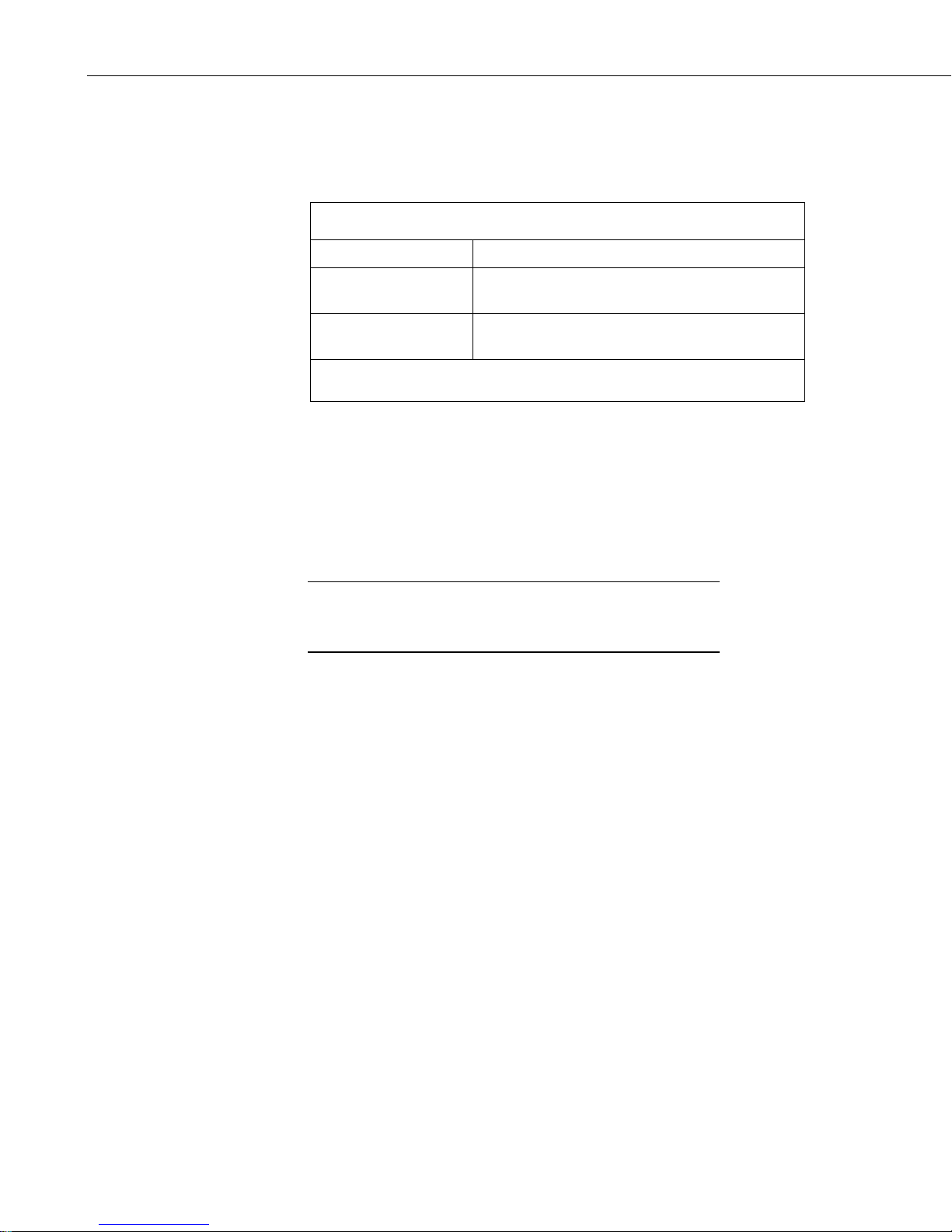
TABLE 4-1. Template Files
NOTE
9. Clic k the Template button in the ACEmanager toolbar. A template
application window will appear. Browse to and upload one of the
configuration templates downloaded from Campbell Scientific. See
TABLE 4-1.
Template File Name Description
RV50_115200.xml
RV50_9600.xml
1
CR1000, CR800 series, CR3000, CR6 series, CR300 series, CR5000
2
CR200(X)
10. Reboot the RV50 after successfully applying the configuration template.
You can do this by clicking the Reboot button on the ACEmanager
toolbar, by momentarily pressing the Reset button (2 sec), or by
temporarily removing power from the RV50.
4.4 Set up LoggerNet
The LoggerNet Network Map is configured from the LoggerNet Setup screen.
Setup has tw o opt ions , EZ (simplified) and Stan dard. Click on the
View menu at the top of the Setup screen, and select Standard
view.
From the LoggerNet toolbar, click Ma i n | Setup and configure the Network
Map as described below.
Default configuration with RS-232 at 115200
1
baud and Ethernet communication enabled.
Default configuration with RS-232 at 9600 baud
2
and Ethernet communication enabled.
1. Select Add Root | IPPort.
2. Add a datalogger to the IPPort (PakBus® dataloggers, for example the
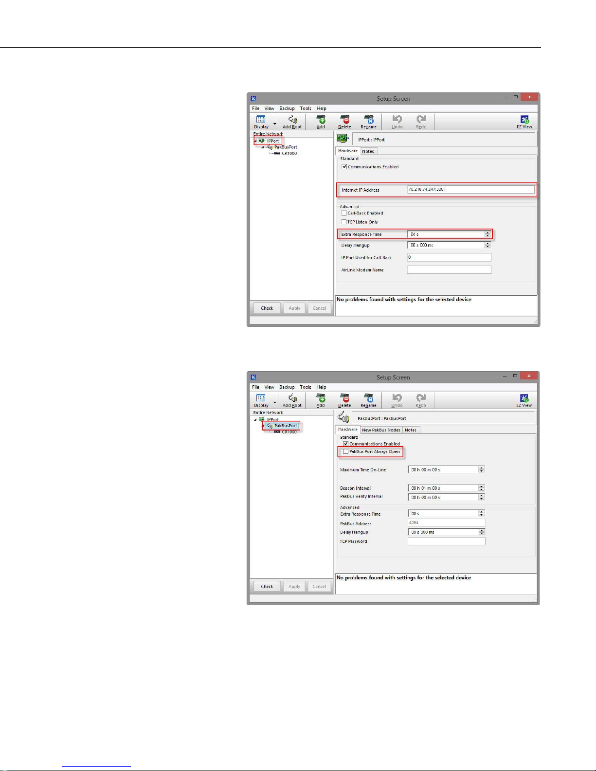
3. Select the IPPort in the Network Map. Enter the RV50 IP address (or
6
CR1000, require a PakBusPort).
domain name) and port number. The IP address and port number are input
in the Internet IP Address field separated by a colon. Preceding zeros are
not entered in the Internet IP Addr e ss (for example, 070.218.074.247 is
entered as 70.218.74.247). Device Configuration Utility (DevConfig) and
the RV50 template file configure the port number to 3001 for serial server
mode. Set the Extra Response Time to 4 seconds.
Page 15
RV50 Sierra Wireless AirLink® 4G LTE Cellular Modem
Example settings for a static IP address:
4. For PakBus dataloggers, leave the default settings for the PakBusPort.
PakBus Port Always Open should not be checked.
7
Page 16
RV50 Sierra Wireless AirLink® 4G LTE Cellular Modem
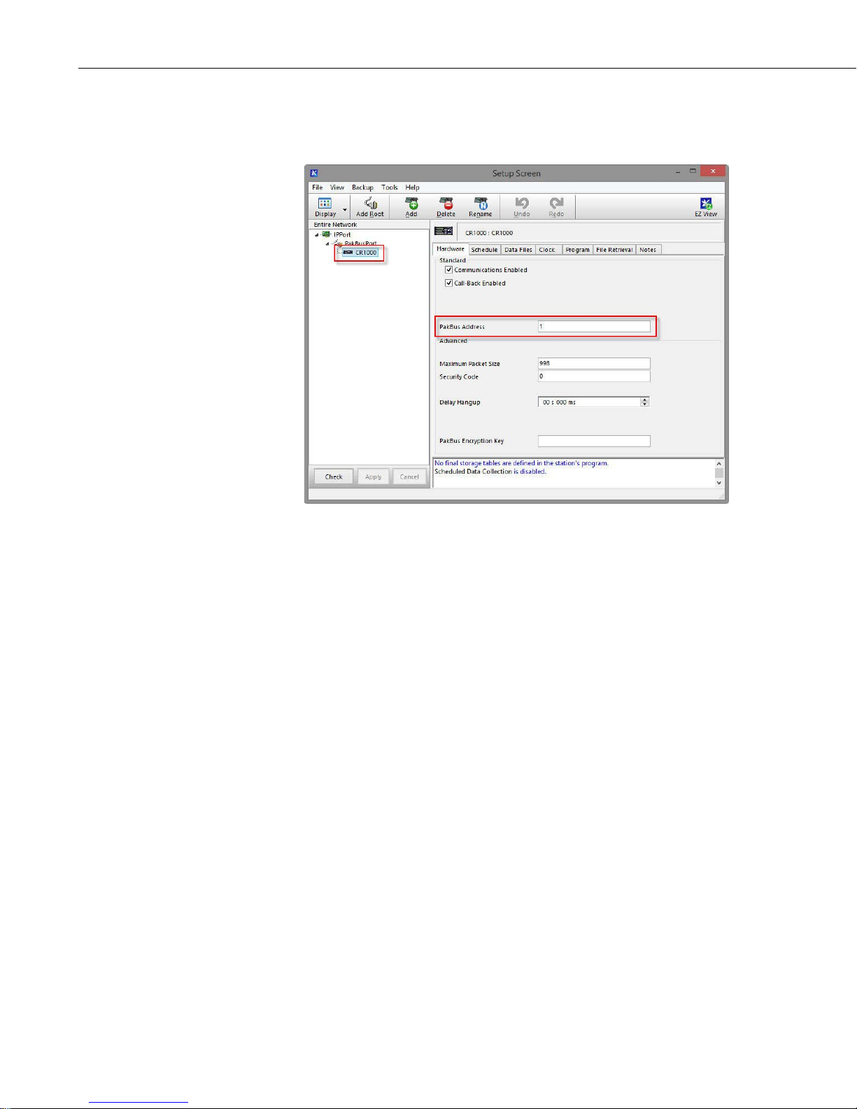
5. For PakBus dataloggers, select the datalogger in the Network Map and set
the PakBus Address to match that of the datalogger (default address in
the datalogger is 1). Click Apply to save the changes.
4.5 Set Up Hardware
The simplest hardware setup for modern dataloggers is to connect a null
modem cable (pn 18663) between the RS-232 ports of the datalogger and the
RV50. See Section 7.4, Wiring and Connections
4.6 Test the Connection
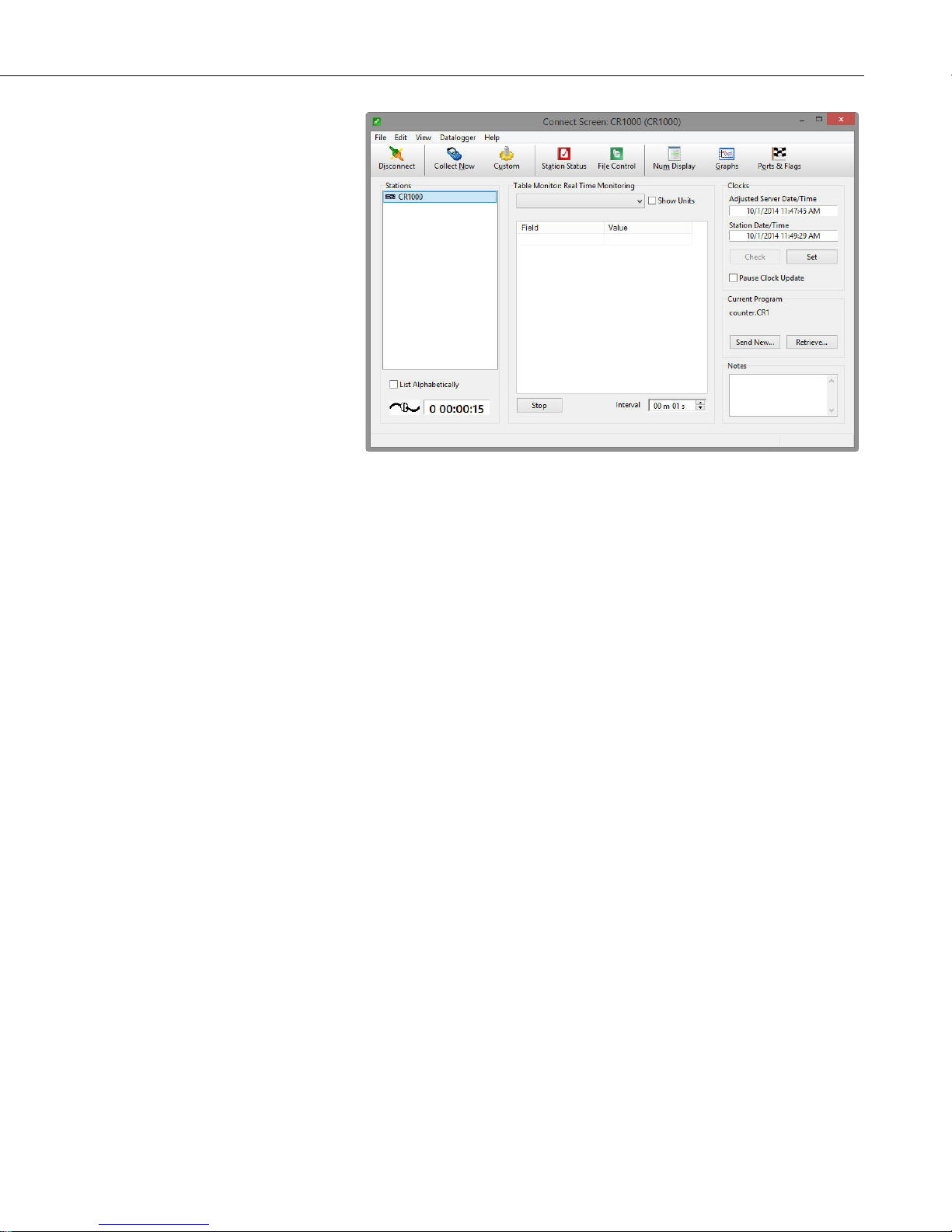
After the Network Map has been configured, test the cellular connection using
the Connect screen as shown below. Click on the ap propriate station and click
Connect to initiate a call to the d a ta logger. If the call is successful, the
connectors at the bottom of the screen will come together and clock
information from the datalogger will be displayed in the Station Date/Time
field. If the conne ction fails, a Communicatio ns F ailure message will be
displayed.
(p. 15).
8
Page 17
5. Overview
RV50 Sierra Wireless AirLink® 4G LTE Cellular Modem
The RV50 mode m m ay be config ured in one of two ways, depending o n t he
communications type and needs of the user. For many applications that just
need a connection for data collection and datalogger maintenance or
monitoring, setup as a serial server is sufficient. In this mode, the modem
receives IP communications over the cellular network and converts those to
serial (RS-232) communications to pass on to the datalogger. From the
datalogger’s perspective, this is no different than a serial cable connecting it to
a PC. Section 4, QuickStart
mode.
Alternatively, if IP communica tions are needed on the datalogger, the modem
may be set up in Point-to-Point Protocol (PPP) mode. In this mode, the modem
simply passes IP communicati ons directly to the datalogger. This enables
features such as FTP, HTTP, and emailing. For information on configuring the
RV50 in PPP mode, see Section 7.5, ACEmanager and Template Files
and Section 7.6, Enabling PPP Mode
the Gmail™ Outgoing SMTP Server
6. Specifications
6.1 RV50 Specifications
Sierra Wireless® AirLink® RV50 cellular modem (MC7354 radio module)
Cellular WAN
(p. 2), describes setting up the RV50 in serial server
(p. 18),
(p. 20). See Appendix B, EmailSend Using
(p. B-1), for more informa t ion on emailing.
• Network Technology: 4G with automatic fallback to 3G and 2G
• Cellular WAN: North American Model
o Carrier Approvals: Verizon®, AT& T®, Sprint®, T-Mobile®
USA, Rogers™, Bell®, Telus®
o LTE: 1900(B2), AWS(B4), 850(B5), 700(B13), 700(B17),
1900(B25)
o WCDMA: 2100(B1), 1900(B2), AWS(B4), 850(B5), 900(B8)
9
Page 18

RV50 Sierra Wireless AirLink® 4G LTE Cellular Modem
o EV-DO/CDMA: 800(BC0), 1900(BC1), 1700(BC10)
o GSM/GPRS/EDGE: Quad-band
o Industry Approvals: FCC, IC, PTCRB
o Software defined radio with automatic network operator
switching
o Dual SIM Interfaces
Host Interfaces
• 10/100/1000 Ethernet RJ45
• RS-232 serial port, DB9 female
• USB version 2.0 with micro-B connector
RF Connectors
• 3 SMA antenna connectors (primary, diversity & GPS)
• Active antenna support
Power
• Operating Voltage: 7 to 36 Vdc
• Typical Enable/Ignition Sense Line Low: 1 mA @ 12V
• Typical Idle: 65 to 95 mA @ 12V, depending on configuration
• Typical Active: 250 to 300 mA @ 12V, depending on configuration
7. Installation
Size
• Dimensions: 119 x 34 x 94 mm (4.69 x 1.34 x 3.7 in)
• Weight: 320 g (11.3 oz)
Environmental
• Operating Temperature Range: –30 to 70 °C (–22 to 158 °F)
• Storage Temperature: –40 to 85 °C (–40 to 185 °F)
• Humidity: 90% @ 60 °C
• Military Specification: MIL-STD-810G conformance to shock,
vibration, thermal sho ck, and humid ity
• IP64 rated ingress protection
Industry Certifications
• Safety: IECEE Certification Bodies Scheme (CB Scheme), UL60950
• Vehicle Usage: E-Mark (UN ECE Regulation 10.04), ISO7637-2,
SAE J1455 (Shock & Vibration)
• Hazardous Environments: Class 1 Div 2
• Environmental: RoHS, REACH, W E EE
7.1 Base Station Requirements for RV50
PC running Campbell Scientific’s LoggerNet or PC400 software with access to
the Internet.
10
Page 19

RV50 Sierra Wireless AirLink® 4G LTE Cellular Modem
7.2 Datalogger Site Equipment
• RV50 modem with power cable (included with modem)
• Datalogger — CR2XX, CR300 series, CR1000, CR5000, CR3000, CR800
series, CR6 series
• Modem Interface
If connecting to RS-232 port:
Null Modem Cable (pn 18663) — connects the modem to the
CR3000, CR800 series, CR2XX, CR300 series, CR1000, or
CR5000 RS-232 port.
CPI/RS-232 RJ45 to DB9 Cable (pn 31055) — connects the
modem to the CR6 CPI/RS-232 port.
If connecting to CS I/O port:
SC105 Interface — any current datalogger with a CS I/O port
The SC105 must be configured for use with the modem usi n g
DevConfig. Settings should be:
CS I/O Mode: SDC Address 7, 8, 10, or 11
RS-232 Mode: Modem
Baud Rate: 115.2K or 9600 baud depending on datalogger model
8 data bits, 1 stop bit, no parity
If connecting to Ethernet port:
Ethernet Cable (pn 28899) — connects the modem to the CR6 or
NLxxx.
• RV50 Mounting Kit (pn 32252) — inc lud es mo u nting hardware for
securing the modem to b elow-referenced environmental enclosure.
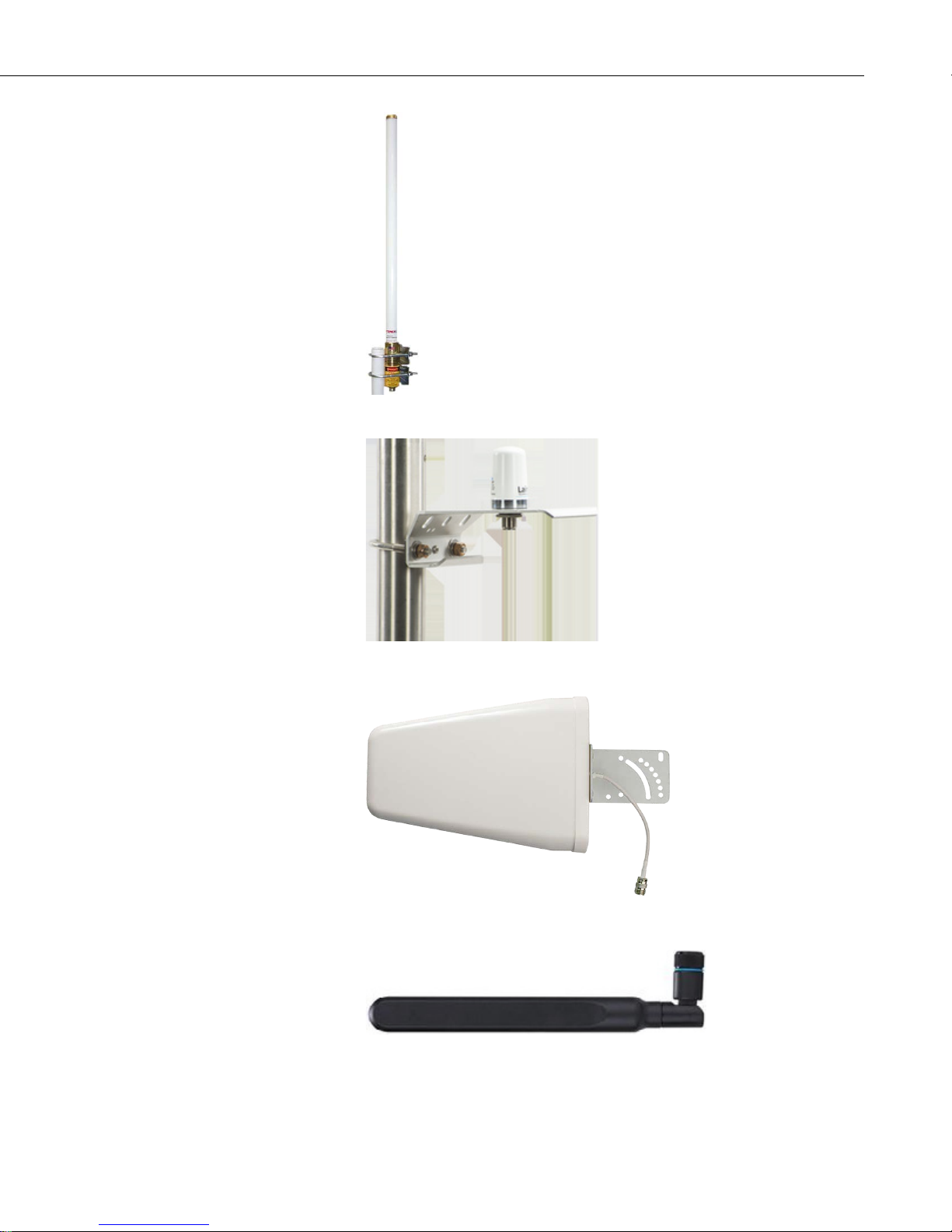
• Antenna — the following antennas are available from Campbell Scientific
(see FIGURE 7-1). Contact a Campbell Scientific application engineer for
help in determining the best antenna for your application.
o The 20679 is a dual-band, omnidirectional antenna for our CDMA
and GPRS/EDGE digital-cellular modems. It covers both the 800MHz band and the 1.9-GHz band. For the 800-MHz band, the 20679
provides a 0-dBd gain. For the 1.9-GHz band, the 20679 provides a 3dBd gain. This antenna is recommended for locations where cellular
coverage is strong.
The 20679 includes a mount/U-bolt assembly that allows the antenna
to be mounted to a mast, crossarm, or user-supplied pole (outer
diameter of up to 3.8 cm (1.5 in)).
o The 32262 is an omnidirectional antenna with mounting bracket that
is ideally suited for use with 4G and 3G cellular gateways. The
11
Page 20

RV50 Sierra Wireless AirLink® 4G LTE Cellular Modem
mounting bracket attaches to a mast or crossarm, and it serves as the
antenna ground plane. The antenna has an N type (female) threaded
permanent stud for easy mounting to the included bracket or through
an enclosure wall. A coaxial cable, sold separately, is required to
connect this antenna to the inline surge suppression or ra dio antenna
jack. The 32262 includes a mount/U-bolt assembly for attaching the
antenna to a mast, post, or crossarm up to 3.8 cm (1.5 in) in diameter.
o The 31128 8 dBd Yagi Antenna is a higher ga in antenna that should
be “aimed” at the service provider’s antenna. It covers both the 800MHz band and the 1.9-GHz band. The 31128 comes with bracket/
U-bolt assembly for attaching the antenna to a mast or post. This
antenna is recommended for fringe areas that require a higher gain
antenna.
o The 32256 is a wideband termination antenna with SMA co nnector
and articulating base. It has a high-efficiency response on nearly all
4G, 3G, and 2G frequency bands and is, therefore, primarily used with
cellular ga teways and routers. This antenna is intended for use inside
the enclosure. Please note that the backplate of the enclosure is a
grounded plane. If it is interposed b e tween the antenna and the cell
tower, it may attenuate the strength of the tra nsmission signal. Simply
turning the enclosure 90 to 180 degrees on its moun ting mast may
solve weak t ransmission issues.
12
Page 21
RV50 Sierra Wireless AirLink® 4G LTE Cellular Modem
Part number 20679 Omnidirectional Antenna
Part number 32262 2 dBd Omnidirectional Antenna
Part number 31128 8dBd Wideband Yagi Antenna
Part number 32256 4G/3G Cellular Whip Antenna
FIGURE 7-1. Antennas for Use with the RV50 Modem
13
Page 22
RV50 Sierra Wireless AirLink® 4G LTE Cellular Modem
• Power Supply — see Section 7.4.2, Modem Power Connections
• Environme ntal Enclosure — ENC10/12, ENC12/14, or ENC16/18
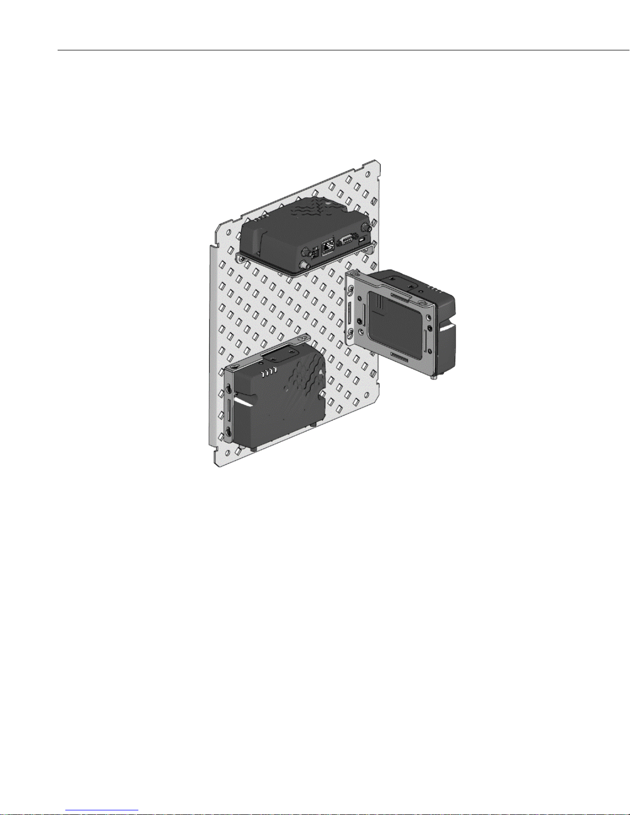
7.3 RV50 Mounting Kit (pn 32252)
(p. 17).
FIGURE 7-2. RV50 Mounting Options
7.3.1 Mounting the RV50 Flat on the Backplate
Use the two included flat-head Phillips scre ws to mount the bracket to the
backplate first. Then use two of the include d pan-head Phillips screws to
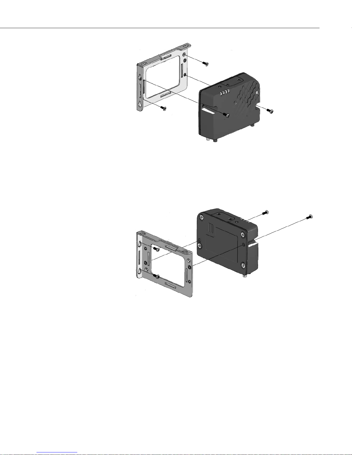
mount the RV50 to the bracket. See FIGURE 7-3.
14
Page 23
RV50 Sierra Wireless AirLink® 4G LTE Cellular Modem
FIGURE 7-3. Flat Mount
7.3.2 Mounting the RV50 on Edge to the Backplate
Use two of the included pan-head Phillips screws to mount the RV50 to the
bracket. Then use two of the included pan-head Phillips screws to mount the
bracket to the backplate. See FIGURE 7-4.
7.4 Wiring and Connections
FIGURE 7-4. Edge Mount
This section explains how to connect the modem for different communication
methods. It also describes how to power the modem and connect an antenna.
15
Page 24
RV50 Sierra Wireless AirLink® 4G LTE Cellular Modem
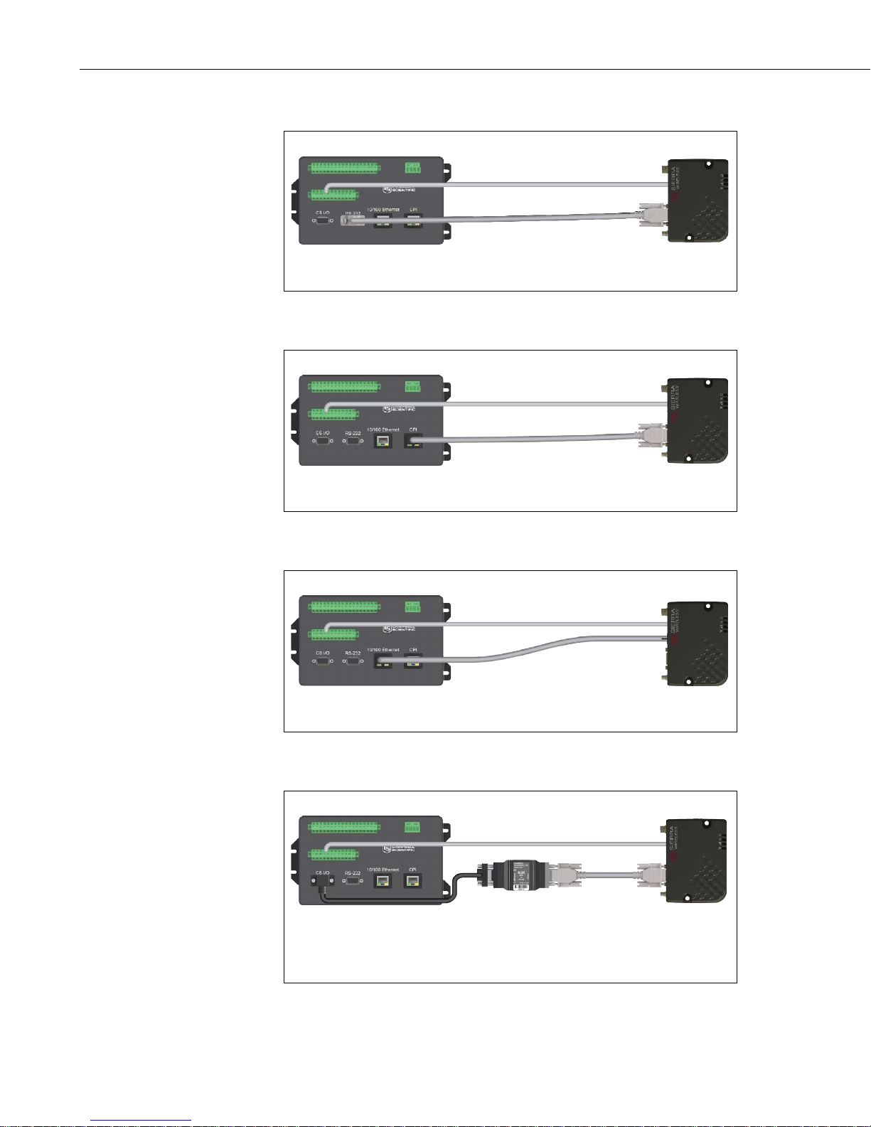
7.4.1 Modem Communication Connections
RS-232 connection using a null modem cable (pn 18663)
Part number 18663, Null Modem Cable, is used to connect the modem to the
CR3000, CR800, CR2XX, CR300 series, CR1000 or CR5000 RS-232 port.
FIGURE 7-5. RS-232 Connection
CR6 RS-232 connection using a CPI/RS-232 cable (pn 31055)
Part number 31055, RS-232/CPI RJ45 to DB9 Male DTE, is used to connect
the modem to the CR6.
FIGURE 7-6. CR6 RS-232 Connection
Ethernet connection
An Ethernet cable (pn 28899) is used to connect the modem to the Ethernet
port of the datalogger, NL1XX, or NL2XX.
FIGURE 7-7. Ethernet Connection
CS I/O connection using an SC105 (pn 16686)
The SC105 interface is used to connect the modem to a datalogger CS I/O
port. The SC105 can be connected directly to the modem RS-232 port.
Alternatively, it can be connected to the modem using the serial cable
supplied with the SC105 (pn 10873).
FIGURE 7-8. CS I/O Connection
16
Page 25
RV50 Sierra Wireless AirLink® 4G LTE Cellular Modem
TABLE 7-1. Power Connections
7.4.2 Modem Power Connections
A power cable is included wit h the mod em and is used to connect the RV50 to
the datalogger 12V terminal. Connection to the switched 12V (SW12V)
terminal or a control port terminal allows the datalogger to switch power to the
modem duri ng scheduled transmission intervals. See Appendix A, Controlling
Power to the RV50
white lead wires to 12V for constant power, t he red to 12V and white to
SW12V or a control port for program-controlled power, and the black lead to
G (ground). The green wire lead is not necessary and can be removed or
insulated. See TABLE 7-1.
When using the SW12V terminal, the modem can typically be powered with a
BP12 battery, a CH150 charger/regulator, and a SP10 solar panel.
RV50 Wiring Lead Color Function Connect To
(p. A-1), for SW12V program examples. Connect the red and
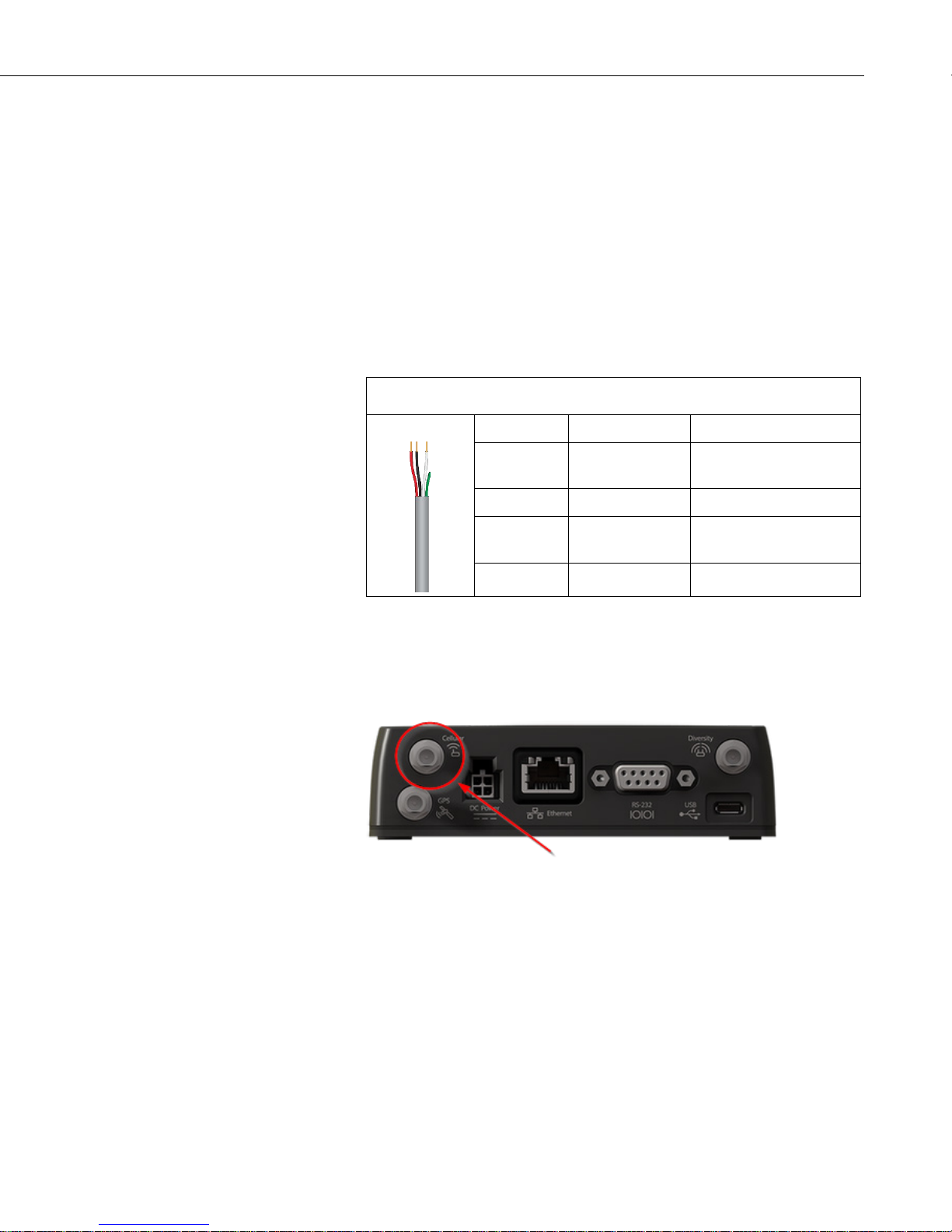
7.4.3 Antenna Connection
Connect the antenna to the Cellular SMA antenna connector as indicated in
FIGURE 7-9.
FIGURE 7-9. Antenna Connection
Red
Power
(10 to 36V)
12V
Black Ground G
White Enable (On/Off)
12V, SW12V, or
Control Port for Control
Green None No Connection
Use of the Diversity antenna can improve performance but is not required. If a
Diversity antenna is not used, use ACEmanager to disable WAN/Celluar |
Network Credentials | RX Diversity.
Antenna diversity, also called space diversity, is a scheme that uses two or
more antennas to improve the qualit y and reliability of a wireless link. Often,
especially in urban and i ndoor enviro n me nts, there is no clear line of sight
between transmitter and receiver. Instead the signal is reflected along multiple
paths before finally being received. Each bounce can introduce phase shifts,
time delays, attenuations, and d isto rtions that can destructively interfere with
one another at the aperture of the receiving antenna.
17
Page 26
RV50 Sierra Wireless AirLink® 4G LTE Cellular Modem
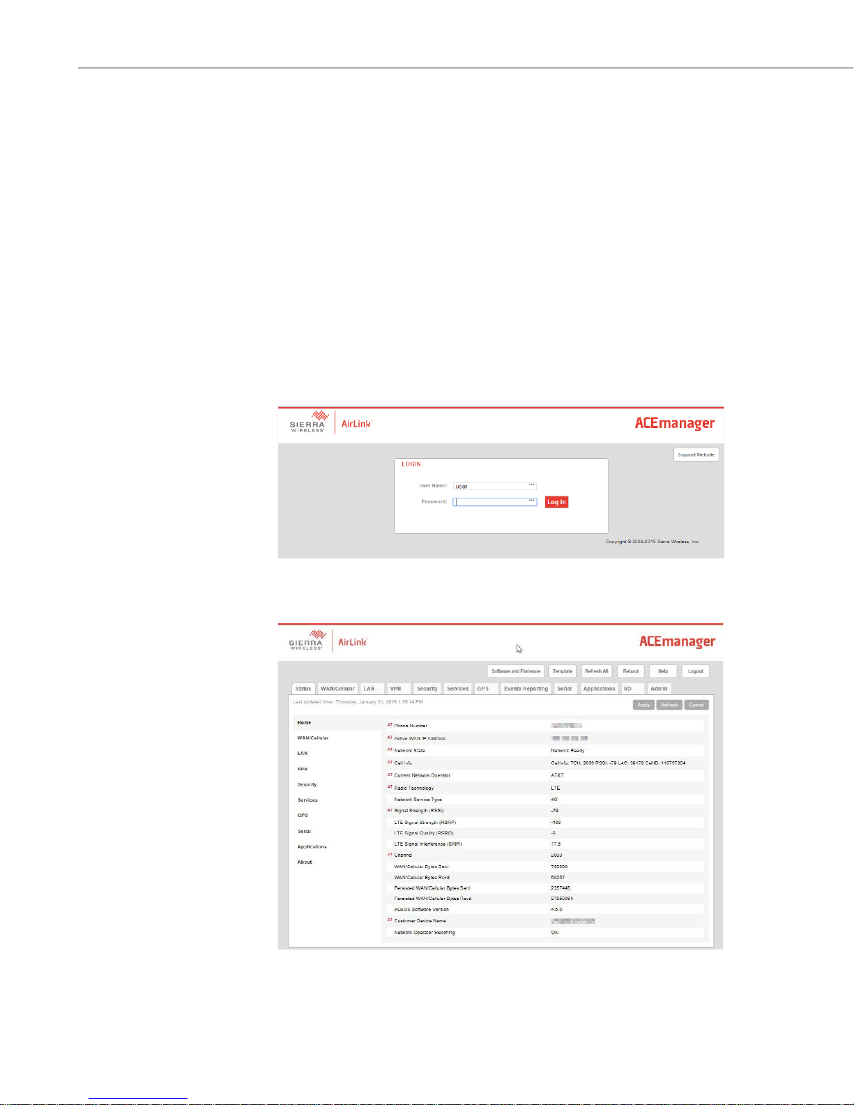
7.5 ACEmanager and Template Files
Section 4, QuickStart (p. 2), d escribes how to set up the RV50 in serial server
mode using ACEmanager. ACEmanager along with template files can be used
to set up the RV50 in serial server mode or PPP.
ACEmanager is accessed via a web browser. For initial setup or
troubleshooting with a direct (cabled) connection, connect a standard Ethernet
(RJ45) cable between the Ethernet port on the PC and that on the modem. Type
http://192.168.13.31:9191 into a web browser.
Once the modem is provisioned on the network, it may be accessed over the air
by typing http:// followed by the IP address (dynamic or static) of the modem,
followed by the port :9191.
The first screen is a login (shown below). The default password is 12345 and it
is strongly recommended to leave it as the default. If security is of concern,
contact a Campbell Scientific applicatio n engineer to discuss options.
After entering the password and pressing enter (or clicking Log In), the
following status screen is disp layed:
18
Page 27
RV50 Sierra Wireless AirLink® 4G LTE Cellular Modem
TABLE 7-2. AceManager Template File s
RV50 template files from Campbell Scientific’s website
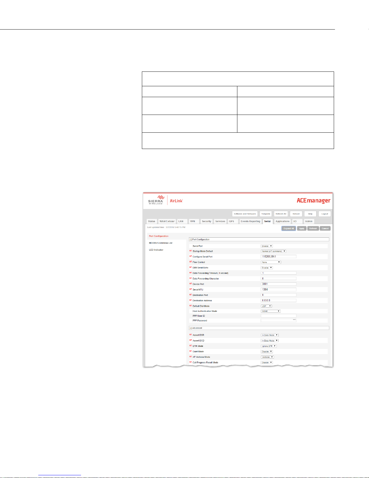
(www.campbellsci.com/downloads) are used to configure the RV50 modem
using ACEmanager. See TABLE 7-2.
Template Files for the RV50 Description
RV50_115200.xml
RV50_9600.xml
1
CR1000, CR800 series, CR3000, CR6 series, CR300 series, CR5000
2
CR200(X)
Serial server mode or PPP mode, for
newer dataloggers
1
Serial server mode, for older
2
dataloggers
that support 9600 baud
Click the Template menu in the top right of the screen. When prompted for a
template file name, select RV50_115200.xml or RV50_9600.xml. The
following screen shows t he settings under the Serial tab after the 115200 baud
template file has been loaded.
19
Page 28
RV50 Sierra Wireless AirLink® 4G LTE Cellular Modem
WARNING
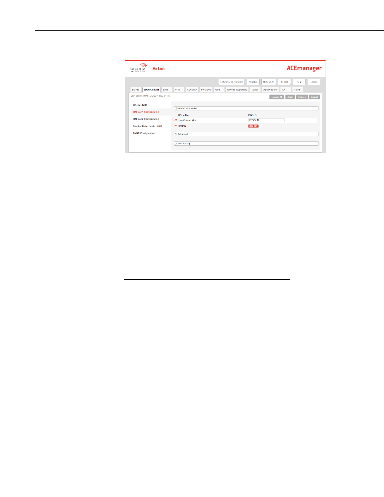
Click on WAN/Cellular for the following screen:
Enter the APN as shown in the screen above. The example is for an APN =
I2GOLD.
After the template file has been loaded, and the APN entered, click Apply to
save the changes in the modem
.
Click Reboot to restart the modem. Alternately, reset the modem by pressing
Reset on the front of the modem or by removing power fro m the modem.
Click Logout to terminate communications with the modem.
Unless you Apply the commands, the changes made
will not be saved in the modem. For most commands,
you must reboot the modem for the newly written values
to take effect.
The modem is now set up in serial ser ver mode. To enable PPP mode, see
Section 7.6, Enabling PPP Mode
7.6 Enabling PPP Mode
The first step in enabling PPP mode is u sing the template file to configure the
RV50 as described in Section 7.5, ACEmanager and Template Files
After configuring the modem, you must use DevConfig to configure the
datalogger for PPP mode.
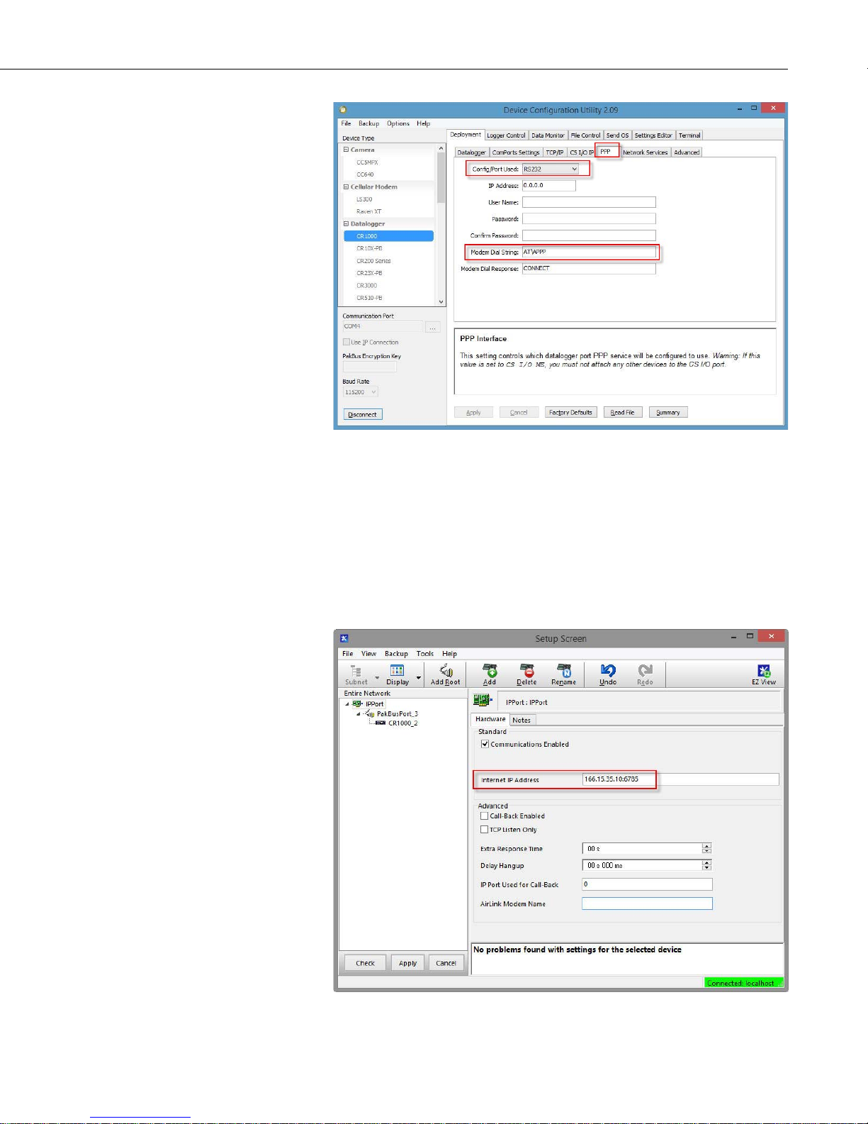
Connect to your datalogger in DevConfig and select Deployment | PPP.
(p. 20).
(p. 18).
20
Page 29
RV50 Sierra Wireless AirLink® 4G LTE Cellular Modem
For the Config/Port Used, use the drop-down list to select the datalo gger p ort
you wish to use for PPP. RS-232 is the standard choice, but any port in the
drop-down list can be used.
Set the Modem Dial String to AT\APPP.
Press Apply to apply the changes.
With PPP e nabled, PakBus®/TCP communications use port 6785. Therefore,
in LoggerNet use :6785 after the IP address or domain name as shown below.
21
Page 30
RV50 Sierra Wireless AirLink® 4G LTE Cellular Modem
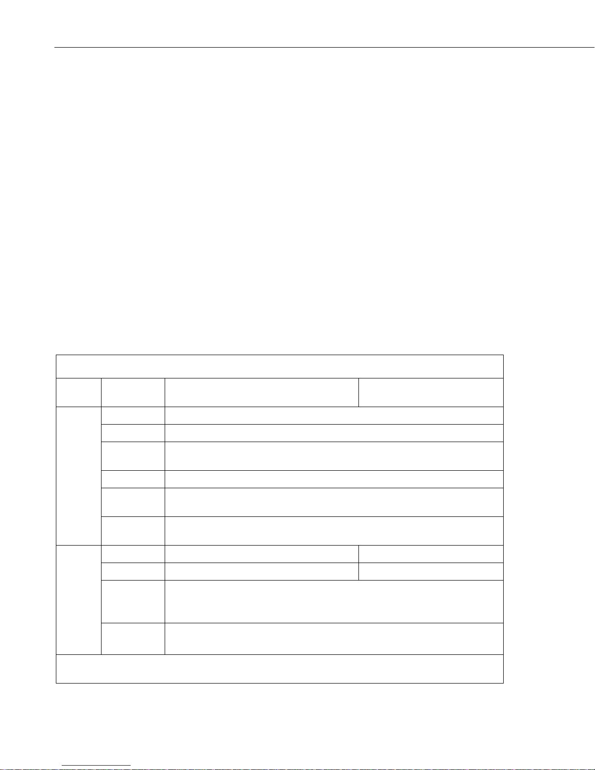
TABLE 8-1. LED Indicator Lights
8. Operation
8.1 Ports
RS-232
The RS-232 port is the main port used with Campbell Scientific dataloggers.
Its function is described throughout this manual.
USB
The USB port is not used i n C ampbell Scientific applications.
Ethernet
The Ethernet port may be used in place of PPP Mode to get to the IP stack of
the datalogger. However, this method comes with hig her current drain for both
the modem and the datalogger. See Appendix D, Using the RV50 Ethernet Port
(p. D-1), for more information.
8.2 LED Indicator Lights
LED
Power
Signal
When your RV50 is connected to p ower and an antenna, there is a specific
pattern to the lights to indicate its operation mode as described in TABLE 8-1.
Color /
Pattern Description LED Power Saving Mode
Off No power or input voltage ≥ 36 Vdc or ≤ 7 Vdc
Solid Green Power is present.
Green with
Amber Flash
Solid Red Standby mode
Flashing
Green
Flashing Red
Solid Green Good signal (equivalent to 4–5 bars) Off
Solid Amber Fair signal (equivalent to 2–3 bars) Off
Flashing
Amber
Power is pre sent and the gateway has a GPS fix.
When you pr ess the reset button, flashing green indicates when to release the reset
button to reboot the gateway.
When you press the reset button, flashing red indicates when to release the reset
button to reset the gateway to the factory default settings.
Poor signal ( equivalent to 1 bar)
If possible, Sierra Wireless® recommends moving the gateway to a loca tion with a
better signal.
Flashing Red
NOTE The quality of the signal strength is measured using the appropriate parameters for the radio
technology in use.
22
Inadequate (equivalent to 0 bars)
Sierra Wireless recommends moving the gateway to a location with a better signal.
Page 31
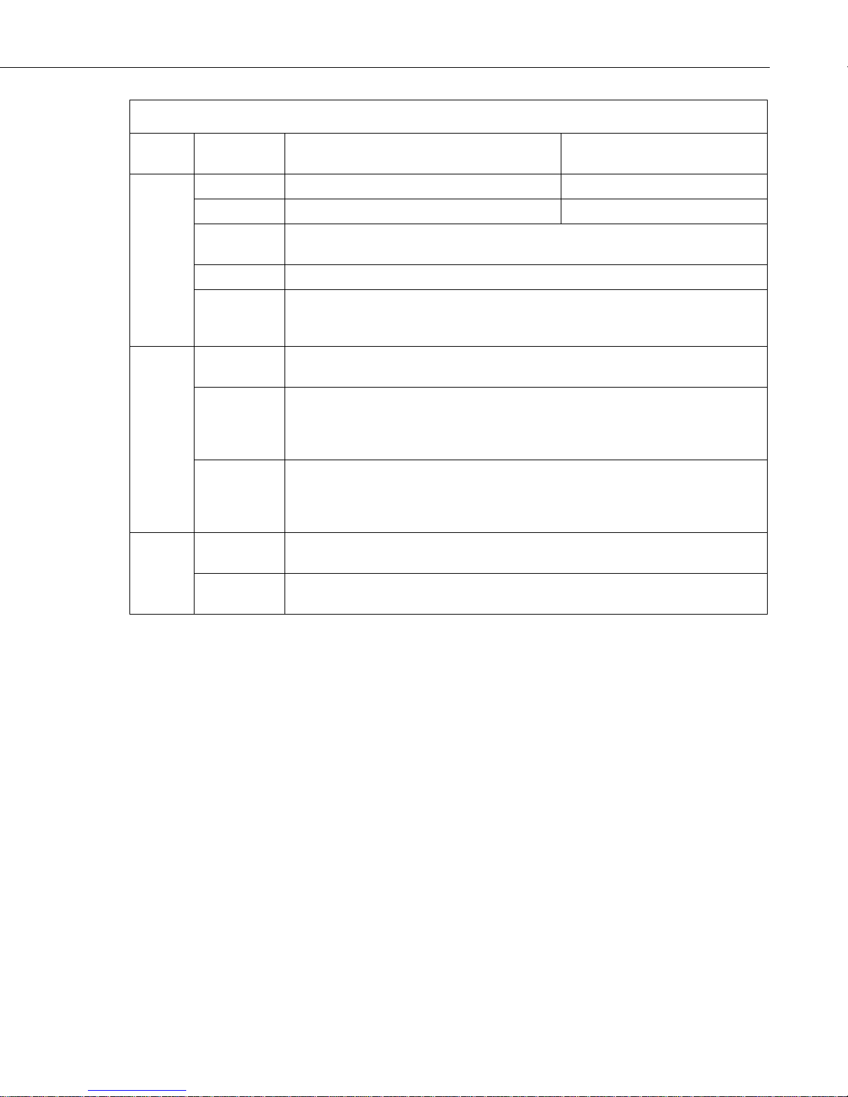
TABLE 8-1. LED Indicator Lights
LED
RV50 Sierra Wireless AirLink® 4G LTE Cellular Modem
Color /
Pattern Description LED Power Saving Mode
Solid Green Connected to an LTE network Off
Solid Amber Connected to a 3G or 2G network Off
Network
Activity
ALL
Flashing
Green
Flashing Red No network available
Flashing Red
/ Amber
Flashing
Green
Flashing Red
Flashing
Amber
Green LED
chase
Amber LED
chase
Connecting t o the network
Network Operator Switching is enabled, but the gateway is unable to locate the
required firmware. For more information, refer to the ALEOS Software
Configuration User Guide (Admin chapter) from the Sierra Wireless website.
Traffic is being transmitted or received over the WAN interface.
Traffic is being transmitted or received o ver the serial port. This behavior only
appears if the RV50 is configured to display it. For more information, refer to the
ALEOS Software Configuration Guide (Serial chapter) from the Sierra Wireless
website.
Traffic is being transmitted or received over both the WAN interface and the serial
port. This behavior only appears if the RV50 is configured to display it. Refer to the
ALEOS Software Configuration Guide (Serial chapter) from the Sierra Wireless
website.
Radio module reconfiguration/firmware update or Network Operator Switching is
in progress.
ALEOS software update is in progress.
8.3 Rebooting the RV50
To reboot the RV50:
• On the RV50, pr ess the Reset button for 1–5 seconds. (Release the
button when the Power LED fla s hes green.)
• In ACEmanager, click the Reboot button on the toolbar.
8.4 Reset the RV50 to Factory Default Settings
To reset the RV50 to the factory default settings:
• On the RV50, pr ess the Reset button for more than 5 seconds.
(Release the button when the Power LED flashes red.) Once the
LEDs resume their normal operating behavior, the reset is complete.
• In ACEmanager, go to Admin | Advanced and click the Reset to
Factory Default button.
23
Page 32

RV50 Sierra Wireless AirLink® 4G LTE Cellular Modem
9. Attributions
AirLink and Sierra Wireless are registered trademarks of Sierra Wireless.
AT&T is a trademark of AT&T Intellectual Property.
Bell is a registered trademark of Bell Canada.
Firefox is a registered trademark of Mozilla Foundation.
Gmail is a trademark of Google Inc.
Internet Explorer and Windows are registered trademarks of Microsoft
Corporation.
PakBus is a registered trademark of Campbell Scientific, Inc.
Rogers is a trademark of Rogers Communications.
Sprint is a registered trade mark of Sprin t.
T-Mobile is a registered trademark of Deutsche Telekom AG.
Telus is a registered trademark of Telus Corporation.
Verizon is a registered trademark of Verizon.
Yahoo is a registered trademark of Yahoo Inc.
All other trademarks or registered trademarks are the property of their
respective owners.
24
Page 33

CRBasic Exampl e A-1. Using TimeIsBetween to Turn On and Off SW12
'CR6 Series
NextScan
Appendix A. Controlling Power to the
RV50
The RV50 uses considerably more power than the datalogger. Therefore, it
may be necessary to use the datalogger to control power to the RV50. The
following program examples show how to control power to the RV50 using the
switched 12V (SW12V) terminal on the datalogger.
CRBasic Example A-1, created by Short Cut, uses the TimeIsBetween
instruction to turn on SW12 for 15 minutes every 60 minutes between 9:00
a.m. and 5:00 p.m. (Note that the TimeIsBetween instruction requires
operating system version 28 or later in the CR1000, CR3000, or CR800. It is
supported in all CR6 and CR300 operating systems.)
'Created by Short Cut (3.1)
'Declare Variables and Units
Public BattV
Public PTemp_C
Public SW12State As Boolean
Units BattV=Volts
Units PTemp_C=Deg C
'Define Data Tables
DataTable(Table2,True,-1)
DataInterval(0,1440,Min,10)
Minimum(1,BattV,FP2,False,False)
EndTable
'Main Program
BeginProg
'Main Scan
Scan(5,Sec,1,0)
'Default Datalogger Battery Voltage measurement 'BattV'
Battery(BattV)
'Default Wiring Panel Temperature measurement 'PTemp_C'
PanelTemp(PTemp_C,60)
'SW12 Timed Control
'Turn ON SW12 between 0900 hours and 1700 hours
'for 15 minutes every 60 minutes
If TimeIsBetween(540,1020,1440,Min) And TimeIsBetween(0,15,60,Min) Then
SW12State=True
Else
SW12State=False
EndIf
'Always turn OFF SW12 if battery drops below 11.5 volts
If BattV<11.5 Then SW12State=False
'Set SW12-1 to the state of 'SW12State' variable
SW12(1,SW12State,0)
'Call Data Tables and Store Data
CallTable Table2
A-1
Page 34

Appendix A. Controlling Power to the RV50
CRBasic Exampl e A-2. Using If Statements to Turn On and Off SW12
NextScan
CRBasic Example A-2, also created by Short Cut, performs the same function
as the first program (turn on SW12 for 15 minutes every 60 minutes between
9:00 a.m. and 5:00 p.m.) without using the TimeIsBetween instruction. This
method should be used for CR1000, CR300 and CR800 operating systems
prior to version 28.
'CR1000
'Created by Short Cut (3.1)
'Declare Variables and Units
Dim MinIntoDay
Public BattV
Public PTemp_C
Public SW12State As Boolean
Units BattV=Volts
Units PTemp_C=Deg C
'Define Data Tables
DataTable(Table2,True,-1)
DataInterval(0,1440,Min,10)
Minimum(1,BattV,FP2,False,False)
EndTable
'Main Program
BeginProg
'Main Scan
Scan(5,Sec,1,0)
'Default Datalogger Battery Voltage measurement 'BattV'
Battery(BattV)
'Default Wiring Panel Temperature measurement 'PTemp_C'
PanelTemp(PTemp_C,_60Hz)
'SW12 Timed Control
'Get minutes into current day
MinIntoDay=Public.TimeStamp(4,1)/60
'Turn ON SW12 between 0900 hours and 1700 hours
'for 15 minutes every 60 minutes
If (MinIntoDay>=540 And MinIntoDay<1020) And ((MinIntoDay-540) Mod 60 < 15) Then
SW12State=True
Else
SW12State=False
EndIf
'Always turn OFF SW12 if battery drops below 11.5 volts
If BattV<11.5 Then SW12State=False
'Set SW12 to the state of 'SW12State' variable
SW12(SW12State)
'Call Data Tables and Store Data
CallTable Table2
A-2
Page 35

NOTE
NOTE
NOTE
Appendix B. EmailSend Using the
Gmail™ Outgoing SMTP Server
The functionality described in this Appendix is not available for
CR5000 or CR200-series dataloggers.
Due to changes by Gmail, the EmailSend program in th is appendix
will only work with our faster dataloggers, the CR6 and the
CR300. For other dataloggers, we suggest another compatible
mail service such as Yahoo®.
The datalogger has a mail client in it si milar to a mail client on a computer. For
the datalogger to send an email, it needs a Simple Mail Transfer Protocol
(SMTP) server to send through like any other mail client. The Gmail SMTP
server can be used for sending outgoing email from the datalogger. Both the
modem and the datalogger must be configured for PPP as described in Section
7.5, ACEmanager and Template Files
(p. 20).
Mode
(p. 18), and Section 7.6, Enabling PPP
B.1 Setting up a Gmail Account
First you need to create a Gmail account, if you do not already have o ne. To
create a Gmail account, go to www.gmail.com from your PC. Gmail accounts
are free of charge.
The credentials to access the mail server will be the username and the password
used when creating the Gmail account.
In the following example progr am you will see:
• ServerAddr set to smtp.gmail.com:587
• UserName set to (the Gmail account user name).
• Password (the one you established at Gmail)
Gmail requires Transport L ayer Security (TLS) to connect to their
mail server. You must go into the Settings Editor in DevConfig to
enable TLS in the datalogger.
In 2013, Gmail changed the way they receive email. The changes require a port
number of 587 to be added to the IP address or server name you are sendin g to
(for example, 174.194.68.108:587, smtp.gmail.com:587). This will allow for
the datalogger to establish a TLS connection with the correct SMTP port on
Gmail’s SMTP servers.
Also, a new security feature has been added to Gmail that will prompt if the
device/PC sending the email is authorized to do so. You will see a message in
the Result variable (of the EmailSend instruction) that refers to op ening yo ur
email account in your web browser. If you see this message, open your web
B-1
Page 36

Appendix B. EmailSend Using the Gmail™ Outgoing SMTP Server
CRBasic Exampl e B-1. Using EmailSend to Se nd a Text Message
'Main program variables
Public EmailServerResp As String * 50
browser and point it to http://email.google.com. Enter the username and
password that your datalogger is using to s end email. You should then see a red
bar at the top of the browser screen. Follow the listed instructions to allow the
datalogger to send email.
B.2 Sending to Multiple Addresses
Sending to multiple email address can be done by using a comma to separate
the email addresses ([email protected], [email protected]).
B.3 Sending a Text Message to a Phone
To send a text message to a phone, the email needs to be converted to a text
message via an email-to-text message gateway. Most cellular providers have an
email-to-text message service for their phone subscribers. To send a text
message to AT&T® Wireless phone subscribers, send a n email to the (10 digit
phone number of the person’s phone)@vtext.com ([email protected]).
Most text messages are limited to 160 characters, so any email messages
greater than 160 characters will be truncated.
Email-to-Text Message Gateways
B.4 EmailSend Program Example
Public Batt, RefTemp, Temp
'declare Email parameter strings (as constants), Message String & Result Variable
Const ServerAddr="smtp.gmail.com:587"
Const UserName="[email protected]"
Const Password="password"
Const ToAddr="[email protected], [email protected]"
Const FromAddr=UserName
Const Subject="Email Message Test"
Const Attach=""
Const CRLF = CHR(13) & CHR(10)
Public AlarmTrigger As Boolean
Dim Message As String * 250
T-Mobile: [email protected]
Virgin Mobile: [email protected]
AT&T: [email protected]
Sprint: [email protected]
Verizon: [email protected]
CRBasic Example B-1 sends an email message when an ala rm condition is
True. Both the CR6 and the RV50 modem must be configured as PPP as
described in Section 7.5, ACEmanager and Template Files
7.6, Enabling PPP Mode
(p. 20). Transport Layer Security (TLS) must be
(p. 18), and Section
enabled in the datalogger to use the Gmail mail server. (TLS is automatically
enabled in the CR6 and CR300 and in the CR1000/CR3000/CR800 with OS
revision 24 or later.)
B-2
Page 37

Public EmailResult
EndProg
Appendix B. EmailSend Using the Gmail™ Outgoing SMTP Server
DataTable (TenSecData,True,-1)
DataInterval (0,10,Sec,10)
Sample (1,Batt,FP2)
Sample (1,Temp,FP2)
EndTable
DataTable(EmailLog,True,10)
Sample (1,EmailResult,FP2)
Sample (1,EmailServerResp,String)
Sample (1,Message,String)
EndTable
BeginProg
Scan (1,Sec,3,0)
Battery (Batt)
PanelTemp (RefTemp,250)
TCDiff (Temp,1,mV200C,U1,TypeT,RefTemp,True ,0,250,1.0,0)
CallTable TenSecData
NextScan
SlowSequence
Do
Delay (1,1,Sec)
'Approximately every 1 second, check for an email alarm condition
'If the temperature has transitioned from below 27 degC to
'to above 28 degC, send an email alarm message
If AlarmTrigger = False Then
If Temp > 28 Then AlarmTrigger = True
If AlarmTrigger Then
'Create email message body
Message = "Warning!" & CRLF & CRLF
Message = Message & "An alarm condition has been identified. "
Message = Message & "The temperature is " & Temp & " degrees C." & CRLF & CRLF
Message = Message & "Datalogger time is " & Status.Timestamp
'Attempt to send the email message
EmailResult=EmailSend
(ServerAddr,ToAddr,FromAddr,Subject,Message,Attach,UserName,Password,EmailServerResp)
CallTable EmailLog
EndIf
EndIf
If Temp < 27 Then AlarmTrigger=False
Loop
B-3
Page 38

Appendix B. EmailSend Using the Gmail™ Outgoing SMTP Server
B-4
Page 39

Appendix C. Configuring the RV50 for
Dynamic IP
Verizon® and AT&T® accounts are provided w ith a static IP address and
do not require the settings described in this section. Accounts with a
dynamic IP address, will require the IP Manager settings described below.
• A static IP address is permanently assigned to a particular account and
will always be used whenever the RV50 connects to the Internet.
• A dynamic IP address is assigned on a “need to have” basis. The
address can change each time the modem or device reconnects to the
network. A dynamic IP address is used with a service such as IP
Manager (described below) to translate a domain name to a dynamic
IP address, so that the RV50 can be contacted by name as if it had a
static IP.
IP Manager is a free service provided by Sierra Wireless® for the RV50 to
translate a dynamic IP address into a fully-qualified domain name, so it can be
contacted directly on the Internet. IP Manager translates a dynamic IP address
to a fully qualified-domain name so yo u can contact your RV50 by name as if
it had a static IP address.
If the RV50 is configured for dynamic IP, when the RV50 fir st connects to the
Internet, it s ends an IP change notific ation to IP Manager. IP Manager will
acknowledge the change and update the dynamic DNS record. The changed IP
address will then be the address for the RV50 configured name. Once the
RV50 IP has been updated in IP Manager, it can be contacted via name.
ACEmanager is used to configure the dynami c IP settings in your RV50 so that
it will use IP Manager as described below.
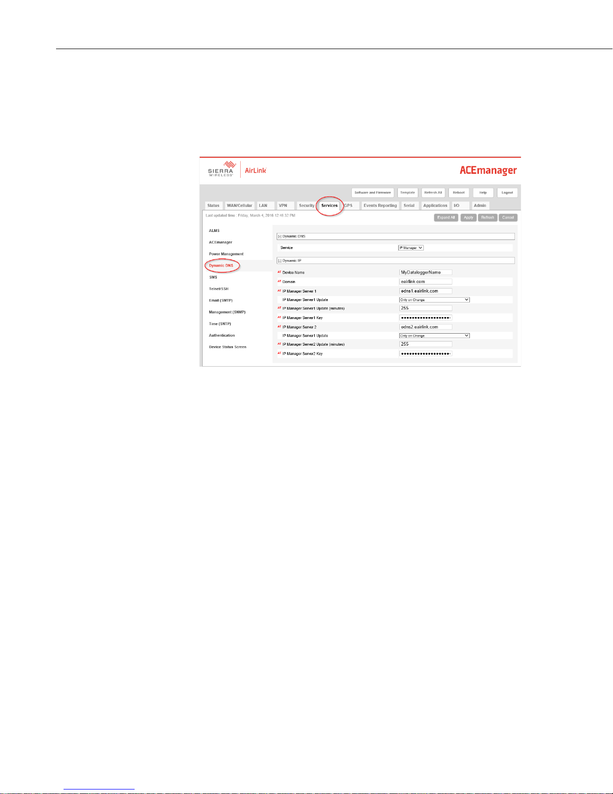
Connect with modem using ACEmanager. Select the dynamic IP group to
configure your modem to use IP Manager.
To configure your Sierra Wireless modem to be addressed by name, the
modem simply needs to ha ve two elements configured: Enable Dynamic DNS
and enter a meaningful name for the Dev ice Name.
• Under the Services tab, select the Dynamic DNS group and use the
drop-down list to select IP Manager. This will reveal the settings
specific to this DNS service.
• Enter a Device Name; this is a unique name for the modem (the 10-
digit MDN number is recommended).
C-1
Page 40
Appendix C. Configuring the RV50 for Dynamic IP
Restrictions for Device Name:
• Must begin with a letter or number
• Can include a hyphen (-)
• Cannot contain spaces
• Must be no longer than 20 characters total
Verify that the Domain, IP Manager Server 1, and IP Manager Server 2 are
the same as above.
Click Apply to save the changes
Click Reboot to restart the modem.
Click Logout to terminate communications with the modem.
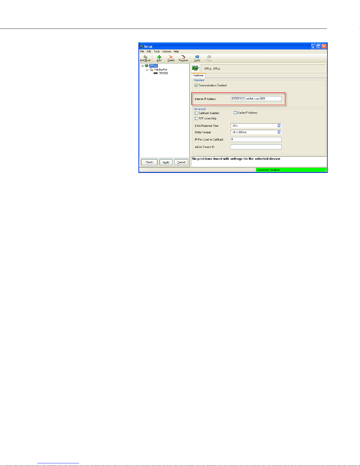
In LoggerNet/PC400, the IP address for PPP is:
modemname.eairlink.com:6785
The IP address for serial server is:
modemname.eairlink.com:3001
.
C-2
Page 41
Appendix C. Configuring the RV50 for Dynamic IP
FIGURE C-1. Serial Server Mode with Dynamic IP
C-3
Page 42

Appendix C. Configuring the RV50 for Dynamic IP
C-4
Page 43
Appendix D. Using the RV50 Ethernet
Port
The RV50 Ethernet port can be used to communicate with IP-enabled devices
such as dataloggers and IP cameras. However, the use of Ethernet
communication increases the total system current demand (the modem and the
device you are connecting to) by several milliamps as compa red to the use of
serial communication.
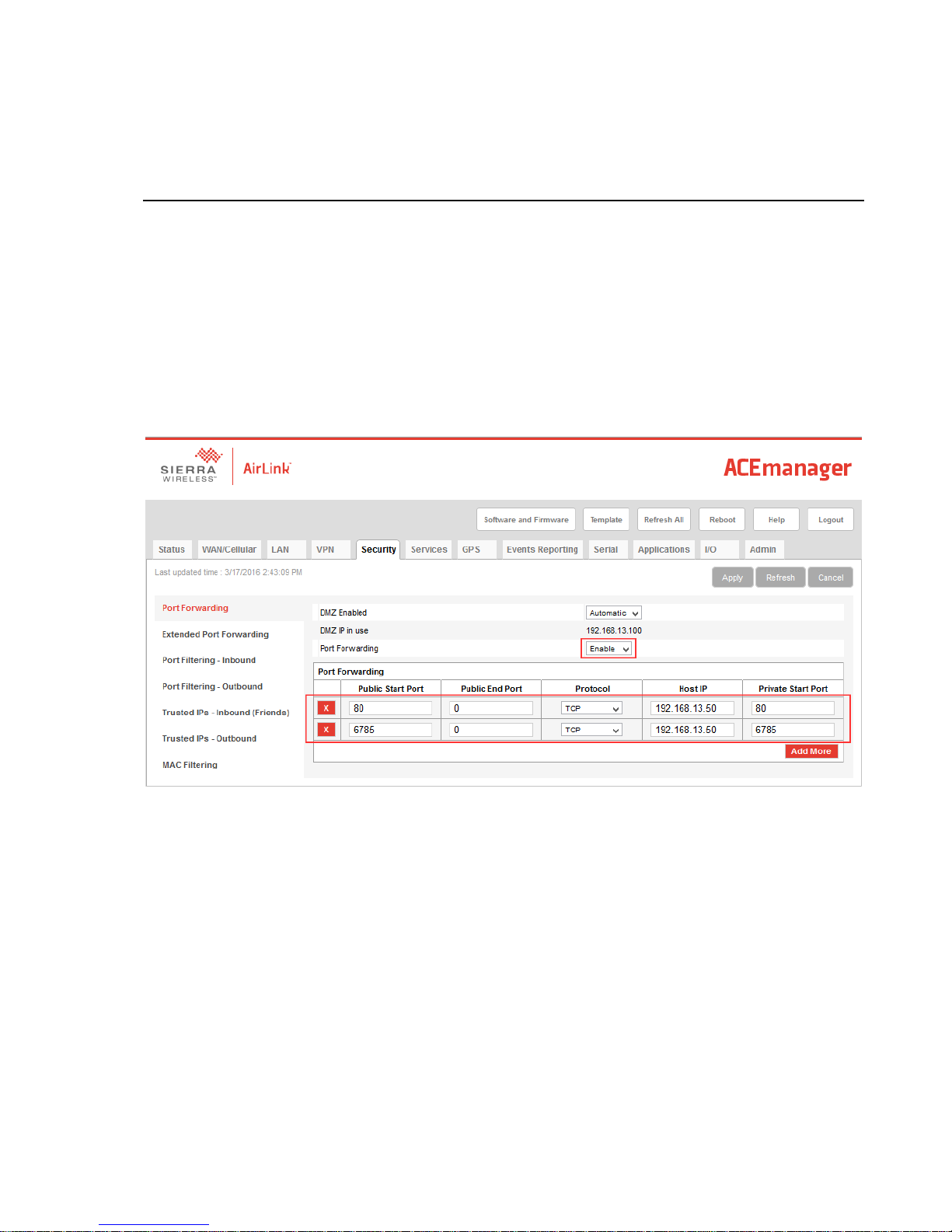
The following example can be used to communicate with a CR1000 / NL121
via the RV50 Ethernet port. Port forwarding in the RV50 must be enabled and
specific ports need to be forwarded to the CR1000 (in this case ports 80 and
6785). Additional ports can be configured as needed. The host IP address
192.168.13.50 specified in the figure below is the IP address of the CR1000.
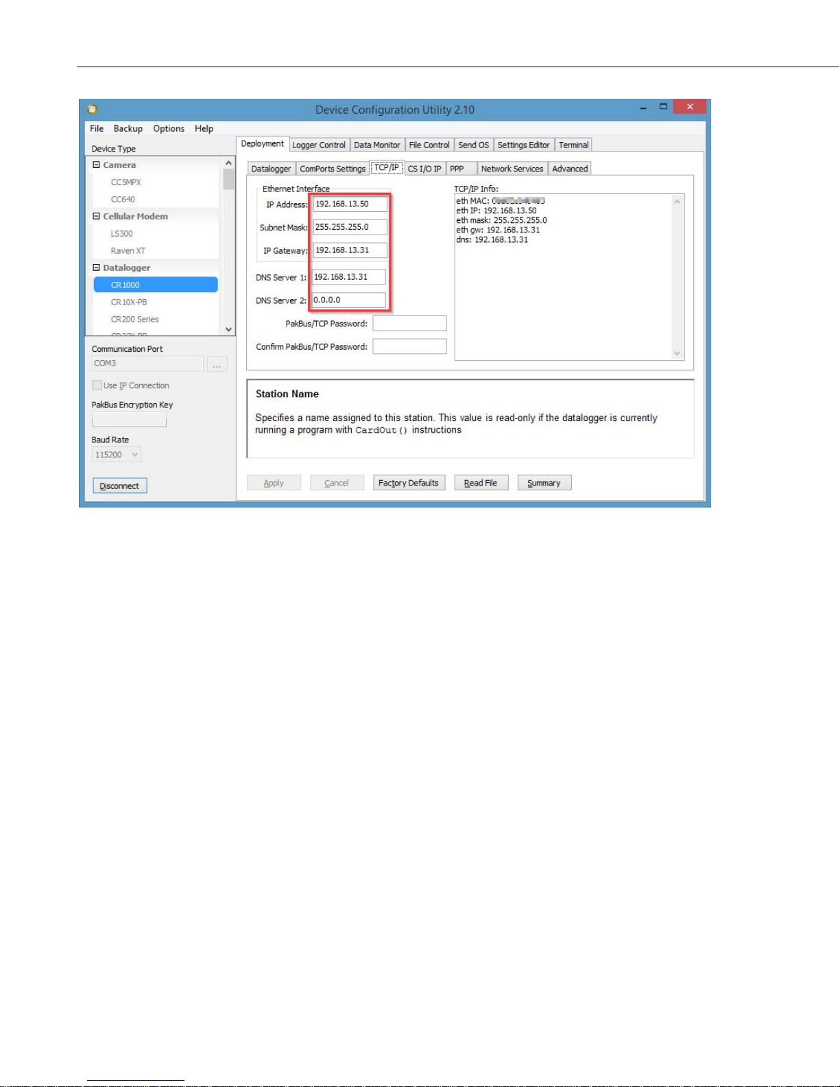
For this example, a static IP A ddress, Subnet Mask, IP Gateway, and DNS
Server is configur ed in the CR1 000 as shown in the figure below. The example
CR1000 IP address of 192.168.13.50 is the same address used in the RV50 port
forwarding configured previously.
D-1
Page 44
Appendix D. Using the RV50 Ethernet Port
Once the RV50 and the CR1000 have been configured and the RV50 has been
rebooted, you can communicate with the CR1000 via LoggerNet using the
public IP address of the RV50 and port 6785. You can also open a web browser
and enter the public IP address of the RV50 to see the default web page of the
CR1000.
D-2
Page 45
NOTE
WARNNG
WARNING
Appendix E. Regulatory Information
This information provided by Sierra Wireless®.
E.1 Important Information for North American Users
This equipment has been tested and found to comply with the
limits for a Class A digital d evice, pursuant to part 15 of the FCC
Rules. These limits are designed to provide reasonable protection
against har mful inte r ferenc e whe n t he eq uip ment is op erated in a
commercial environment. This equipment generates, uses, and can
radiate radio frequency energy and, if not installed and used in
accordance with the instruction manual, may cause harmful
interference to radio communications. Operation of this
equipment in a residential area is likely to cause harmful
interference, in which case the user will be required to correct the
interference at his own expense.
Changes or modifications to this device not expressly
approved by Sierra Wireless could void the user’s
authority to operate this equipment.
E.2 RF Exposure
In accordance with FCC/IC requirements of human exposure to radio
frequency fields, the radiating e lement shall be installed such that a minimum
separation distance of 20 cm should be maintained from
user’s body.
This product is only to be installed by qualified
personnel.
To comply with FCC/IC regulations limiting both maximum RF output power
and human exposure to RF radiation, the maximum antenna gain must not
exceed the specifications listed below for the device used.
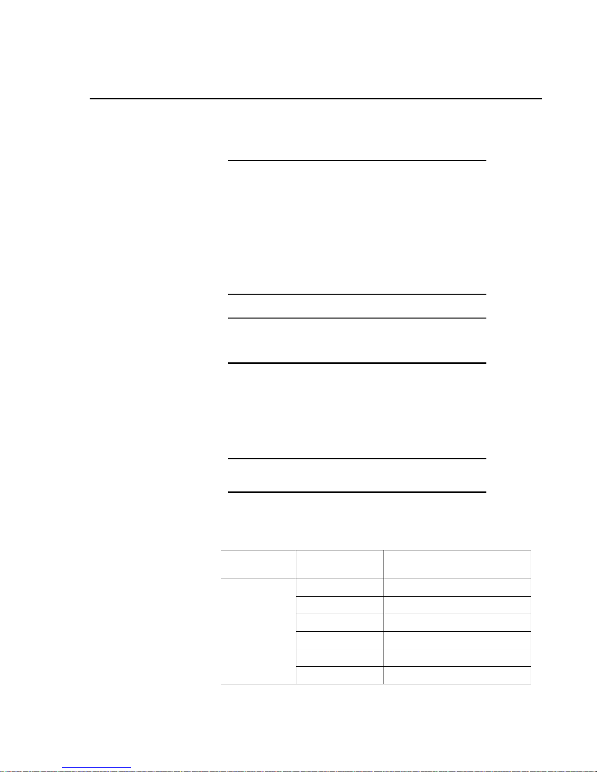
Device Frequency Band
Cellular Band 6.5 dBi
PCS Band 3.0 dBi
the anten na and the
FCC ID/IC Number
N7NMC7355 2417C-MC7355
AirLink RV50
Band 4 6.0 dBi
Band 13 9.0 dBi
Band 17 9.0 dBi
Band 25 3.0 dBi
E-1
Page 46
Appendix E. Regulatory Information
WARNING
WARNING
E.3 EU
Sierra Wireless hereby declares the AirLink RV50 devices is in compliance
with
1999/5/EC.
The RV50 d isp la ys the CE mar k.
Changes or modifications to this device not expressly
approved by Sierra Wireless could void the user’s
authority to operate this equipment.
This product is only to be installed by qualified
personnel.
the essenti al requirements and other relevant provisions of Directive
E.4 Declaration of Conformity
The Declaration of Conformity made under Directive 1999/5/EC is available
for viewing at: http://source.sierrawireless.com/resources/airlink/-
certification_and_type_approval/rv50_ce_declaration_of_conformity/.
E-2
Page 47
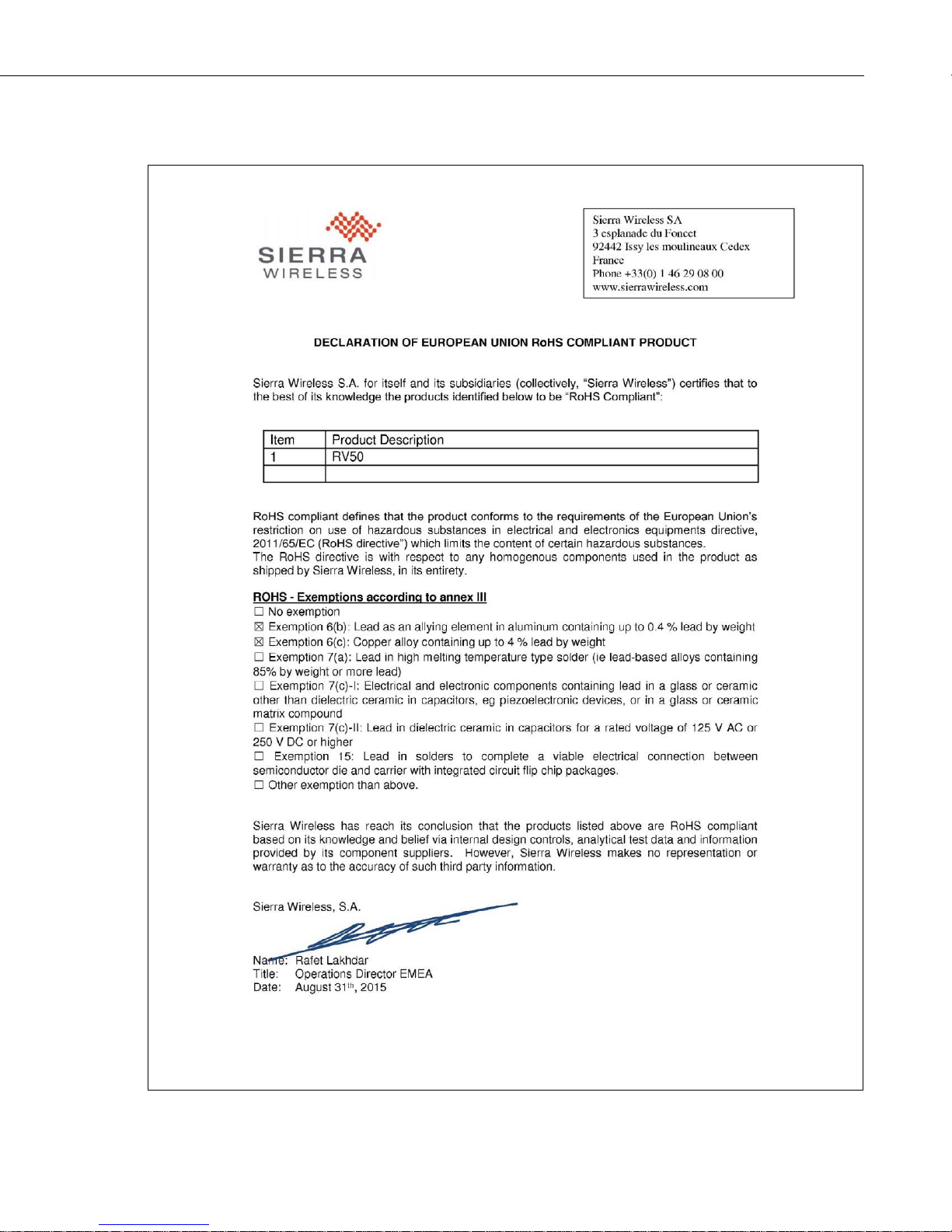
E.5 RoHS Compliance
Appendix E. Regulatory Information
E-3
Page 48

Appendix E. Regulatory Information
E-4
Page 49

Page 50

Campbell Scientific Companies
Campbell Scientific, Inc.
815 West 1800 North
Logan, Utah 84321
UNITED STATES
www.campbellsci.com • [email protected]
Campbell Scientific Africa Pty. Ltd.
PO Box 2450
Somerset West 7129
SOUTH AFRICA
www.campbellsci.co.za • [email protected]
Campbell Scientific Southeast Asia Co., Ltd.
877/22 Nirvana@Work, Rama 9 Road
Suan Luang Subdistrict, Suan Luang District
Bangkok 10250
THAILAND
www.campbellsci.asia • [email protected]
Campbell Scientific Australia Pty. Ltd.
PO Box 8108
Garbutt Post Shop QLD 4814
AUSTRALIA
www.campbellsci.com.au • [email protected]
Campbell Scientific (Beijing) Co., Ltd.
8B16, Floor 8 Tower B, Hanwei Plaza
7 Guanghua Road
Chaoyang, Beijing 100004
P.R. CHINA
www.campbellsci.com • [email protected]
Campbell Scientific do Brasil Ltda.
Rua Apinagés, nbr. 2018 ─ Perdizes
CEP: 01258-00 ─ São Paulo ─ SP
BRASIL
www.campbellsci.com.br • [email protected]
Please visit www.campbellsci.com to obtain contact information for your local US or international representative.
Campbell Scientific Canada Corp.
14532 – 131 Avenue NW
Edmonton AB T5L 4X4
CANADA
www.campbellsci.ca • [email protected]
Campbell Scientific Centro Caribe S.A.
300 N Cementerio, Edificio Breller
Santo Domingo, Heredia 40305
COSTA RICA
www.campbellsci.cc • [email protected]
Campbell Scientific Ltd.
Campbell Park
80 Hathern Road
Shepshed, Loughborough LE12 9GX
UNITED KINGDOM
www.campbellsci.co.uk • [email protected]
Campbell Scientific Ltd.
3 Avenue de la Division Leclerc
92160 ANTONY
FRANCE
www.campbellsci.fr • [email protected]
Campbell Scientific Ltd.
Fahrenheitstraße 13
28359 Bremen
GERMANY
www.campbellsci.de • [email protected]
Campbell Scientific Spain, S. L.
Avda. Pompeu Fabra 7-9, local 1
08024 Barcelona
SPAIN
www.campbellsci.es • in
 Loading...