


Safire 3
3G/HD/SD real-time chroma keyer
Crystal Vision Ltd., Lion Technology Park, Station Road East, Whittlesford, Cambridge, CB22 4WL, England.
Tel: +44(0) 1223 497049 Fax: +44(0) 1223 497059 sales@crystalvision.tv www.crystalvision.tv

Crystal Vision Safire 3 User Manual
Contents
1 Introduction 5
Block Diagram 6
2 Hardware installation 8
Board configuration 8
Link Configuration 8
3 Rear modules 9
Rear module connections with RM50 9
Rear module connections with RM73 10
4 General Purpose Interface 11
Introduction 11
Indigo DT desk top box GPI connections 13
1U frame GPI connections 14
2U frame GPI connections 14
5 VisionPanel 15
Introduction 15
Panel Overview 16
Mounting 16
Connecting 17
Setting Up 18
Operation 21
6 VisionWeb Control 23
Introduction 23
Connecting 24
Menu Tree 24
7 Control Descriptions 29
Auto Setup 29
Gain & Spill 31
Edges and Key Remove 33
Hue and Balance 34
Lighting Compensation 35
Safire 3 User Manual R1.3 1 24 March 2017

Crystal Vision Safire 3 User Manual
Brightness & Contrast 36
FG Colour Correct 37
Filters & Re-Spill 37
Output Signal 39
Keys & Masks 39
Internal FG Mask 41
Internal BG Mask 41
FG/BG Source & Matte 42
FG Mask Softness 42
BG Mask Softness 43
Signal Status 43
Key Status 44
Key Fade 45
Presets 46
Delay & Timing 46
Engineering 47
8 Using Safire 3 50
Auto Setup 52
Foreground Suppression 53
Background Key 56
Additional Controls 57
Re-Spill 60
Foreground Tints 61
Lighting Compensation 61
Colour Adjust 61
Keys and Masks 61
External Key 62
External Mask 64
Internal Masks 65
9 Key Signals 68
Chroma key 68
Self Key 68
External Key 69
External Mask 70
10 Chroma Key Tips 71
Lighting 71
Safire 3 User Manual R1.3 2 24 March 2017

Crystal Vision Safire 3 User Manual
Subject Placement 71
Background 71
Clothing 71
Reflective Foreground Objects 71
11 Troubleshooting 72
Card edge monitoring 72
Basic fault finding guide 72
12 Specification 73
13 Appendix 1 75
Statesman Control 75
Statesman operation 75
Status & Presets 76
Signal Status 76
Key Status 77
Presets 77
Chroma Key 78
Auto Setup 78
Manual Setup 80
Fine Tune 83
Chroma Key Adjust 83
Chroma Key Refine 84
Colour Adjust 85
FG & BG Colour Match 85
FG Colour Correct 86
Keyers & Effects 87
Keyers 87
Effects 89
Masks 90
FG Mask 90
BG Mask 91
Engineering 91
Signals 91
Timing 92
Safire 3 User Manual R1.3 3 24 March 2017

Crystal Vision Safire 3 User Manual
R1.1 Major revision to whole manual, including addition of Safire 3
Controller and VisionWeb Control and removal of front panel and board
edge control. Statesman control moved to appendix.
R1.2 Safire 3 Controller renamed as VisionPanel. Updated panel operation
and GUIs.
R1.3 Clarified GPI section. 29/07/16
02/04/14
23/10/15
Safire 3 User Manual R1.3 4 24 March 2017

Crystal Vision Introduction
1 Introduction
Safire 3 is a modular real-time chroma keyer for 3Gb/s, HD and SD sources. Ideal for
live virtual productions from studio to sport. It includes enhanced key processing
features to create a realistic key as well as video delay and foreground colour
correction. The main features are as follows:
• Use with any source – works with 3Gb/s, HD and SD.
• Supports the following video standards: 625i, 525i, 720p50, 720p59.94,
720p60, 1080i50, 1080i59.94, 1080i60, 1080p23.98, 1080p24, 1080p25,
1080p29.97, 1080p30, 1080p50, 1080p59.94, 1080p60, 1080PsF23.98,
1080PsF24, 1080PsF25, 1080PsF29.97, 1080PsF30, 2048x1080p23.98*,
2048x1080p24*, 2048x1080p25*, 2048x1080p29.97*, 2048x1080p30*,
2048x1080PsF23.98*, 2048x1080PsF24*, 2048x1080PsF25*,
2048x1080PsF29.97*, 2048x1080PsF30* (*= YUV 4:2:2 10 bit).
• Key on any colour – select any key colour including grass.
• Auto setup – cursor based auto setup produces optimal chroma key result.
• Optimise the video – video proc-amps allows adjustment of foreground and
background video gains and black levels to provide the most realistic composite
image after chroma keying. RGB gain and lift of the Foreground video signal.
• Offset the graphic generator’s delay – up to ten frames of video delay for each
input.
• Correct timing errors automatically – each input has a frame synchroniser
timed to an external reference or selected input.
• Internal mask generator – to overrule the chroma keyer to force areas to be
foreground or background. Use to prevent unwanted keying from reflective
objects or to force keying if the backdrop is too small or damaged.
• External key input – use Safire 3 as a linear keyer to key graphics into a video
source, or use as a chroma key mask.
• Internal matte generator – use as a fill for Foreground and Background keys.
• Fade keys – fade keys up and down with an auto-transition or manually.
• Fade to Black – fade main output to black with an auto-transition or manually.
• Two video outputs – independent Main and Aux outputs feature routable
sources to display all inputs and outputs.
• Control of Safire 3 is most easily achieved by VisionPanel or VisionWeb Control
web browser software. Control can additionally be from SNMP.
• GPI control of configuration set-ups and key fade.
• Supports the following rear module connectors: RM50, RM73.
Safire 3 User Manual R1.3 5 24 March 2017

Crystal Vision Introduction
• Compatible with Crystal Vision standard frames available in 2U, 1U and desk
top box.
• Passes all ancillary data.
Block Diagram
Safire 3 simplified block diagram
Block Diagram Description
The Foreground (FG), Background (BG) and External Key video inputs are firstly
frame synchronised, delayed and timed to an external analogue Black and Burst or
tri-level syncs reference, or to one of the other inputs.
The FG signal is then passed to the FG suppression block where, in Suppress
Foreground mode, all colours in the FG acceptance window are de-saturated to
shades of grey and any colour exactly the same as the FG hue colour will be
suppressed to black. Luminance is subtracted from the suppressed signal to ensure
that all the coloured backdrop area is black. In Multiply Foreground mode the
suppression block is bypassed.
A key is derived from the chroma key processing block which is maximum for FG
colours exactly the same as the Chroma Key Colour hue. All other colours within the
Chroma Key Colour acceptance window will produce varying amounts of key from
maximum in the centre to zero at the edges. The clipped chroma key is combined
with other keys and masks to produce a single key which is used to cut a hole in the
Background video – and in Multiply Foreground mode only, the inverse key cuts a
hole in the FG signal as well.
Safire 3 User Manual R1.3 6 24 March 2017

Crystal Vision Introduction
The FG and BG signal are mixed with their selected video, matte or black fills before
being added together to make the final composite output.
Safire 3 User Manual R1.3 7 24 March 2017

Crystal Vision Hardware installation
to be 10.0.0.201
PL2
GPI 1 Input = RS422 Rx+
GPI 1 Input = GPI 1
PL3
GPI 2 Input = RS422 Rx-
GPI 2 Input = GPI 2
PL4
GPI 3 Input = RS422 Tx+
GPI 3 Input = GPI 3
PL5
GPI 4 Input = RS422 Tx-
GPI 4 Input = GPI 4
2 Hardware installation
Board configuration
Safire 3 main board top-side
Link Configuration
There are four user-settable links on the Safire 3. These are PL2-5, all other links should be left in the position shown in the above picture. PL2-5 set whether the board’s GPI inputs are used as GPIs or as an extra serial I/O port.
Link Towards front of board or Up Towards the rear of board or Down
J1 Sync input unterminated. Sync input terminated by 75 ohms
J9 Debug mode – forces board’s IP address
Normal mode (factory set, do not alter)
Safire 3 User Manual R1.3 8 24 March 2017
Front Edge LEDs
PSU HD SD
On if power
supply OK
On if reference signal is
HD format
On if reference signal is
SD form at
Crystal Vision Rear modules
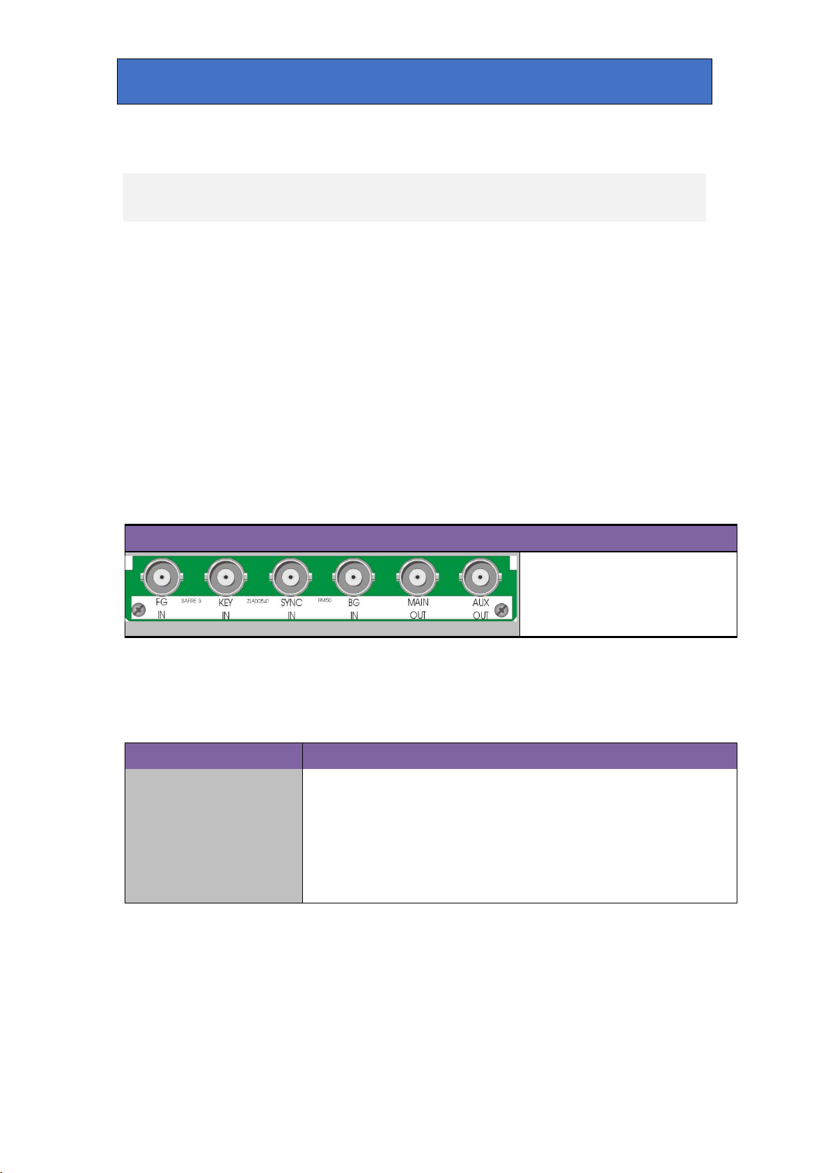
RM50 rear module connector
Description
RM50
• All frame slots can be used
3 Rear modules
The 2U Indigo 2 frame will house up to 12 single height modules and dual power
supplies. The 1U Indigo 1 frame will house six single height modules and a single or
dual power supply. The Indigo DT desk top boxes have a built-in power supply and
will house up to two single height modules. All modules can be plugged in and
removed while the frame is powered without damage.
Note: For details of fitting rear connectors please refer to the appropriate frame manual.
Safire 3 can support the following rear modules: RM50, RM73.
Rear module connections with RM50
The RM50 being a single height module will allow maximum packing density with the
maximum number of inputs and outputs available.
BNC connections
BNC
FG IN
KEY IN
SYNC IN
BG IN
MAIN OUT
AUX OUT
• 12 per Indigo 2 frame
• Six per Indigo 1 frame
• Two per Indigo DT
I/O assignment
3G/High Definition/Standard Definition serial digital input
3G/High Definition/Standard Definition serial digital input
Analogue Black & Burst or tri-level syncs reference for video synchroniser
3G/High Definition/Standard Definition serial digital input
3G/High Definition/Standard Definition serial digital output
3G/High Definition/Standard Definition serial digital output
Safire 3 User Manual R1.3 9 24 March 2017
Crystal Vision Rear modules
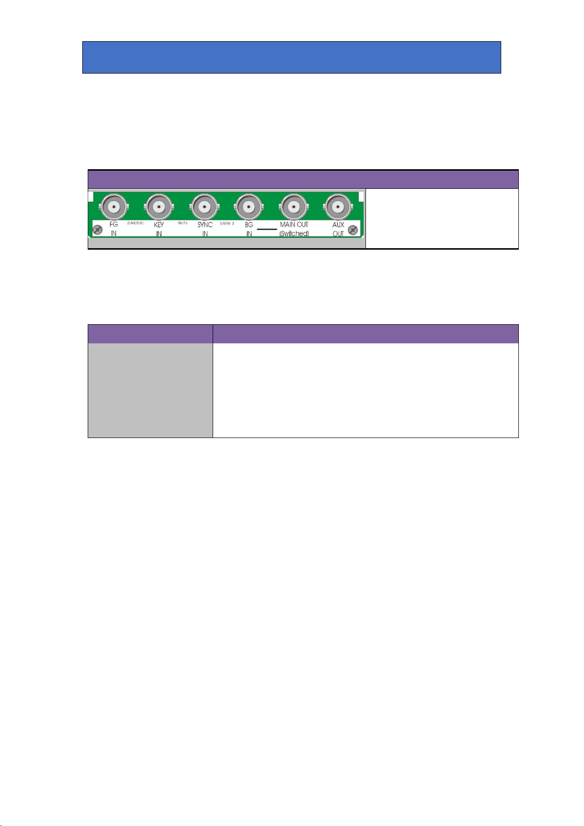
RM73 rear module connector
Description
RM73
All frame slots can be used
Rear module connections with RM73
The RM73 being a single height module will allow maximum packing density with the
maximum number of outputs available. This module features relay bypass protection,
automatically switching the main output to BG IN in the event of power failure.
• 12 per Indigo 2 frame
• Six per Indigo 1 frame
• Two per Indigo DT
•
BNC connections
BNC
FG IN
KEY IN
SYNC IN
BG IN
MAIN OUT (SWITCHED)
AUX OUT
I/O assignment
3G/High Definition/Standard Definition serial digital input
3G/High Definition/Standard Definition serial digital input
Analogue Black & Burst or tri-level syncs reference for video synchroniser
3G/High Definition/Standard Definition serial digital input
3G/High Definition/Standard Definition serial digital output
3G/High Definition/Standard Definition serial digital output
Safire 3 User Manual R1.3 10 24 March 2017
Crystal Vision General Purpose Interface
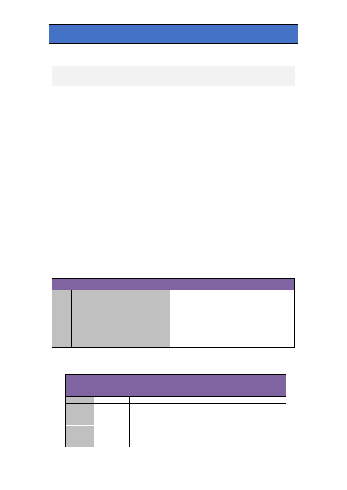
2
‘b’
Recall preset bit 2
GPI
Bit 16
Bit 8
Bit 4
Bit 2
Bit 1
Preset
1
H
H
H
H
H 2 H
H
H
H
L 3 H
H
H
L
H 4 H
H
H
L
L 5 H
H
L
H
H 6 H
H
L
H
L 7 H
H
L
L
H
4 General Purpose Interface
Introduction
Each frame slot has up to six connections ‘a-f’ for GPI control and monitoring. These
connections are available at the rear of the frame on the 26-way D-Type remote connectors.
Safire 3 has six GPI inputs. Five recall one of 32 presets and the sixth is used to trigger an
auto transition of the Key Fade (see GPI Fade Keys control description).
Each General Purpose Interface (GPI) input is fitted with a 10kΩ resistor connected to the
internal +5V and in the following table, this equates to logic ‘H’. With the GPI preset recall
lines set to ‘level’ mode and no connections (logic ‘HHHHH’), preset 1 will be selected. With
the GPI preset recall lines set to ‘pulse’ mode, the GPI will be activated whenever a bit is
pulled low but no change to the preset selection will occur when all bits return to logic
‘HHHHH’. Note that preset 32 is not accessible in pulse mode.
Note: Because the GPI inputs are sampled in the vertical interval it is recommended that in
‘pulse’ mode, the GPI should be asserted at least 2mS before the start of vertical sync to
ensure stability and held active for at least 40mS.
See Presets, Resets & GPI/Os in this manual for details of inverting the GPI preset logic.
Each General Purpose Interface output has a 270Ω resistor in series with its output. This
allows for an external LED to be driven, connected to a DC voltage of +5V.
The GPI inputs can be programmed to automatically recall a previously saved preset
configuration. The 32 user preset configurations are selected using binary notation. Presets
33-40 are only accessible via VisionWeb or VisionPanel.
GPI Low (<1V) High (+5V)
1 ‘a’ Recall preset bit 1
3 ‘c’ Recall preset bit 4
4 ‘d’ Recall preset bit 8
5 ‘e’ Recall preset bit 16
6 ‘f’ Fade Key Autotrans
Table showing the six GPI functions
See following table for user preset control
Trigger Autotrans (see GPI Fade Keys Setup)
Safire 3 User Manual R1.3 11 24 March 2017
Crystal Vision General Purpose Interface
8
H
H
L
L
L 9 H
L
H
H
H
10
H
L
H
H
L
11
H
L
H
L
H
12
H
L
H
L
L
13
H
L
L
H
H
14
H
L
L
H
L
15
H
L
L
L
H
16
H
L
L
L
L
17
L
H
H H H
18
L
H
H
H
L
19
L
H
H
L
H
20
L
H
H
L
L
21
L
H
L H H
22
L
H
L H L
23
L
H
L
L
H
24
L
H
L
L
L
25
L
L
H
H
H
26
L
L
H
H
L
27
L
L
H
L
H
28
L
L
H
L
L
29
L
L
L
H
H
30
L
L
L
H
L
31
L
L
L
L
H
32
L
L
L
L
L
GPI
Bit 16
Bit 8
Bit 4
Bit 2
Bit 1
No change
1
2
3
4
5
6
7
8
9
10
11
12
13
14
15
16
17
18
19
20
21
Binary coding of GPI inputs to recall preset configurations in level mode.
Preset
Safire 3 User Manual R1.3 12 24 March 2017

Crystal Vision General Purpose Interface
22
23
24
25
26
27
28
29
30
31
32
Not accessible in pulse mode
1
8 (1)
9 (1)
18 (1)
26 (1)
19 (2)
20 (2)
2
7 (1)
16 (1)
17 (1)
25 (1)
10 (2)
11 (2)
Note:
Remote 1: 26-way high-density D-Type female socket. Frame ground is pin
1A.
Binary coding of GPI inputs to recall preset configurations in pulse mode.
Indigo DT desk top box GPI connections
GPI lines ‘a’ to ‘f’ of each card connect to two rear remote connectors as follows:
Slot no. ‘a’ pin ‘b’ pin ‘c’ pin ‘d’ pin ‘e’ pin ‘f’ pin
Table shows pin number (remote number)
2 and +5V @500mA is pin 1.
Remote 2: 26-way high-density D-Type male plugs and frame ground is pin
6 and +5V @500mA is pin 15.
Note: The +5V output is protected by self-resetting thermal fuses, which
limit the total output current available from Remotes 1-2 to approximately
Safire 3 User Manual R1.3 13 24 March 2017

Crystal Vision General Purpose Interface
Slot no.
‘a’ pin
‘b’ pin
‘c’ pin
‘d’ pin
‘e’ pin
‘f’ pin
1
8 (1)
9 (1)
18 (1)
26 (1)
19 (2)
20 (2)
2
7 (1)
16 (1)
17 (1)
25 (1)
10 (2)
11 (2)
3
5 (1)
6 (1)
15 (1)
24 (1)
1 (2)
2 (2)
4
4 (1)
14 (1)
13 (1)
23 (1)
3 (2)
4 (2)
5
3 (1)
12 (1)
22 (1)
21 (1)
12 (2)
13 (2)
6
10 (1)
11 (1)
19 (1)
20 (1)
21 (2)
22 (2)
Note:
Remote 1: 26-way high-density D-Type female socket. Frame ground is
1A.
Slot no.
‘a’ pin
‘b’ pin
‘c’ pin
‘d’ pin
‘e’ pin
‘f’ pin
1
8 (1)
9 (1)
18 (1)
26 (1)
19 (2)
20 (2)
2
7 (1)
16 (1)
17 (1)
25 (1)
10 (2)
11 (2)
3
8 (3)
9 (3)
18 (3)
26 (3)
19 (4)
20 (4)
4
7 (3)
16 (3)
17 (3)
25 (3)
10 (4)
11 (4)
5
5 (1)
6 (1)
15 (1)
24 (1)
1 (2)
2 (2)
6
4 (1)
14 (1)
13 (1)
23 (1)
3 (2)
4 (2)
7
5 (3)
6 (3)
15 (3)
24 (3)
1 (4)
2 (4)
8
4 (3)
14 (3)
13 (3)
23 (3)
3 (4)
4 (4)
9
3 (1)
12 (1)
22 (1)
21 (1)
12 (2)
13 (2)
10
10 (1)
11 (1)
19 (1)
20 (1)
21 (2)
22 (2)
11
3 (3)
12 (3)
22 (3)
21 (3)
12 (4)
13 (4)
12
10 (3)
11 (3)
19 (3)
20 (3)
21 (4)
22 (4)
Remote 1 and Remote 3 are 26-way high-density D-Type female
approximately 1A.
1U frame GPI connections
GPI lines ‘a’ to ‘f’ of each card connect to two rear remote connectors as follows:
Table shows pin number (remote number)
pin 2 and +5V @500mA is pin 1.
Remote 2: 26-way high-density D-Type male plugs and frame ground is
pin 6 and +5V @500mA is pin 15.
Note: The +5V output is protected by self-resetting thermal fuses, which
limit the total output current available from Remotes 1-2 to approximately
2U frame GPI connections
GPI lines ‘a’ to ‘f’ of each card connect to two of four rear remote connectors as
follows:
Table shows pin number (remote number)
Note:
sockets. Frame ground is pin 2 and +5V @500mA is pin 1 in each case.
Remote 2 and Remote 4 are 26-way high-density D-Type male plugs
and frame ground is pin 6 in each case and +5V @500mA is pin 15 on
Remote 2.
Note: The +5V output is protected by self-resetting thermal fuses, which
limit the total output current available from Remotes 1-4 to
Safire 3 User Manual R1.3 14 24 March 2017

Crystal Vision VisionPanel
Button
Function
Select Channel 1 as the device to control or Channel 5 if the
‘Shift’ button is held down.
Select Channel 2 as the device to control or Channel 6 if the
‘Shift’ button is held down.
Select Channel 3 as the device to control or Channel 7 if the
‘Shift’ button is held down.
Select Channel 4 as the device to control or Channel 8 if the
‘Shift’ button is held down.
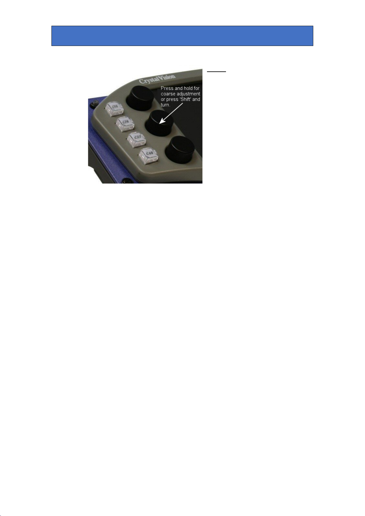
Hold down to select alternate function. Hold down for knob
coarse adjustment.
Jump directly into the outputs menu, allowing you to quickly
monitor your incoming and outgoing signals.
Jump to the presets menu, allowing the quick recalling or
storing of a preset.
Go back a menu level or jump to the ‘Home’ menu, if the ‘Shift’
available.
5 VisionPanel
Introduction
VisionPanel is a stylish 3U control panel for the hands-on control of up to 16 frames
containing Crystal Vision products including the Safire 3 and Safire 3 Xpress chroma keyers.
Multiple VisionPanels can be installed – allowing any device to be controlled from a number of
locations. It can also be used alongside the VisionWeb web browser control for simultaneous
operation of systems.
VisionPanel features eight hard buttons that have the following function:
C 1/5
C 2/6
C 3/7
C 4/8
Shift
Outputs
Presets
Back/Home
Devices, which can be a mix of Crystal Vision cards, can be assigned to one of eight
channels by using the card management menu (see below). The four buttons on the left of
VisionPanel in conjunction with the ‘Shift’ button ( top right) allow you to select which one of
eight devices you want to control but should your system contain more than eight devices,
you can easily select additional ones to control using the ‘Cards List’ menu (see below) on the
touch screen.
Soft buttons on the touch screen are used in conjunction with physical knobs to access the
various intuitive setup menus, which allow the key processing, masks and engineering
settings to be configured with ease. Fades can be implemented using one of these soft
buttons or by using a GPI.
VisionPanel is designed to operate the Safire 3 over Ethernet using standard CAT5 cables.
Just plug the panel into your Ethernet network to connect to the Safire 3 chroma keyers set
up on that network.
button is held down, where all the top level menu options are
Safire 3 User Manual R1.3 15 24 March 2017

Crystal Vision VisionPanel
Panel Overview
Mounting
VisionPanel can be mounted on a desk, inside a desk or in a 19” rack using the
supplied mounting ears.
The desk stand brackets can be mounted in two orientations as shown below.
The panel is shipped with the brackets pre-fitted to the shallower orientation. To
change to the steep orientation undo the four fixing screws and reverse the
Safire 3 User Manual R1.3 16 24 March 2017

Crystal Vision VisionPanel
brackets so the left hand bracket is fitted to the right and vice versa.
Connecting
VisionPanel requires an Ethernet link to the Crystal Vision frame housing the
Safire 3 chroma keyer. The Crystal Vision frame must therefore be Ethernet
capable such as the Indigo 2SE/2AE or equivalent 1U or desk top models. See
the frame specific manuals for details on how to assign an IP address to the
frame.
Connect VisionPanel to the same network as the Crystal Vision frame using a
standard CAT5 network cable. Direct connections from the panel to the frame are
also supported and do not require a crossover cable.
Screw the supplied 9V External PSU onto the power connector on the rear of the
VisionPanel.
Safire 3 User Manual R1.3 17 24 March 2017
Crystal Vision VisionPanel
Setting Up
When first powering VisionPanel you will need to set the panel’s network settings.
The procedure is as follows:
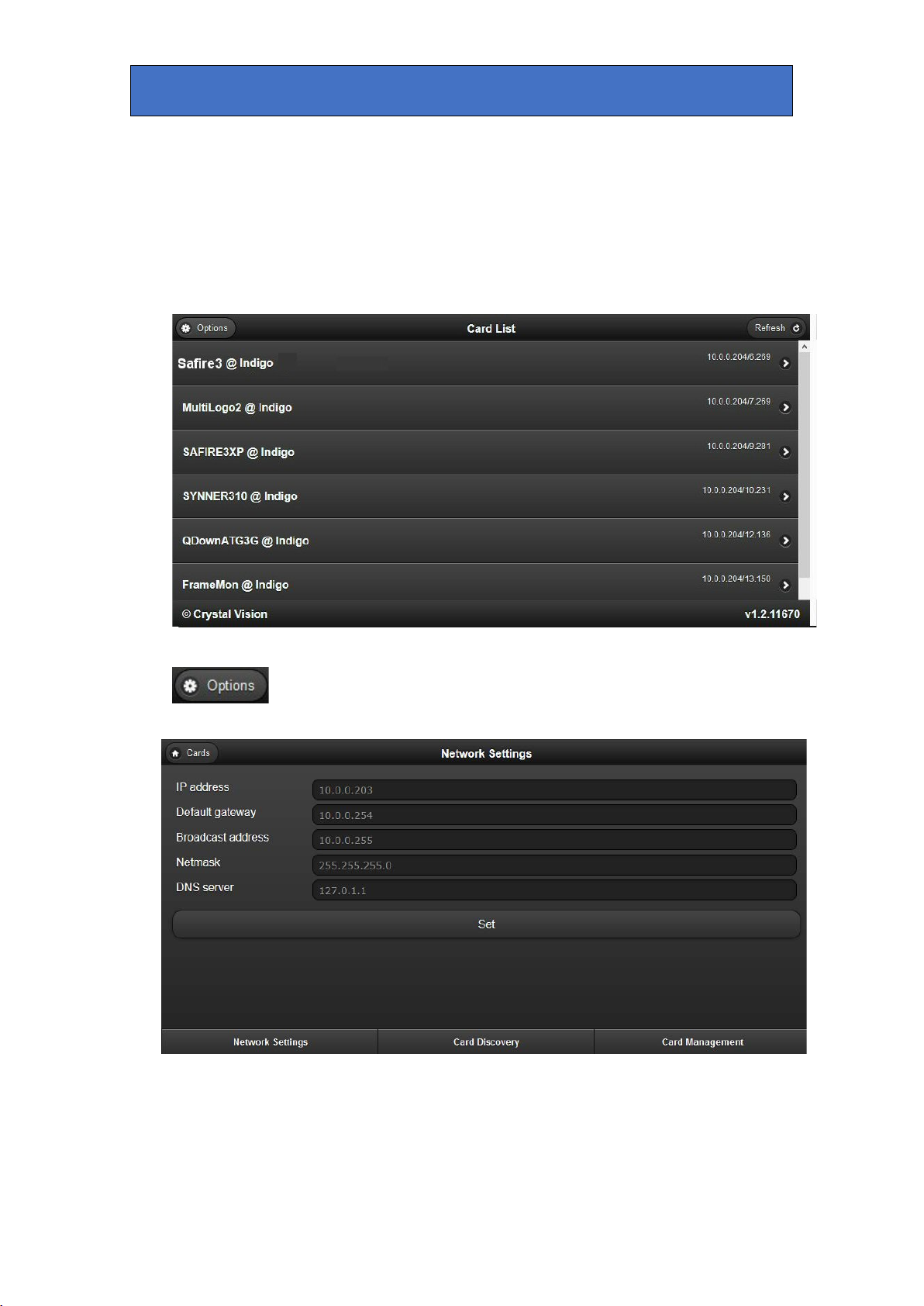
1. Turn VisionPanel on using the power button on the front of the control panel. The
screen will display the ‘Card List’ menu which will eventually be filled by the names and
locations of detected cards:
Example of Card List display showing a number of Crystal Vision cards
2. Press the “Options” button at the top left of the touch screen and the
‘Network Settings’ menu will be displayed:
Example of Network Settings display.
3. Using the pop-up on screen keyboard, enter the following address fields in ‘dotdecimal’ notation:
IP Address – the panel’s IP Address.
Safire 3 User Manual R1.3 18 24 March 2017

Crystal Vision VisionPanel
Default Gateway – the address of any device that must be addressed in order to
access devices within external networks, usually the router’s IP address.
Netmask address – this selects the range of network addresses that are checked
when identifying devices within a network. For instance a Netmask of 255.255.255.0
will only test the first 24 bits of IP addresses. So a panel with an IP address of
10.0.0.203 and with the netmask above will consider all devices with an IP address
of 10.0.0.xx as part of the same network.
Broadcast address – the address that a packet uses to broadcast to the whole
network and is usually the IP address of the panel but with all bits that are zero in
the netmask set to 1. So the broadcast address in the above example would be
10.0.0.255.
DNS Server – this is the address of a server that translates domain names and IP
addresses.
Note: The Broadcast address and DNS server information is not currently used so
can be left at the default values.
4. Press ‘Set’ when all the fields have been entered.
5. Press the ‘Card Discovery’ tab to enter IP addresses of the frames you want to
scan:
Example of ‘Card Discovery’ display.
6. Enter the IP addresses and port number 80 (e.g. 10.0.0.201:80) of all the frames you
wish to control, up to a maximum of 16 frames. Press ‘Add’ to include an IP address or
‘Delete’ to remove it.
7. Press ‘Discover’ to make the panel search the IP addresses in the list and create a new
list of cards (the old card list will be deleted).
8. Select ‘Card Management’ to assign different cards to the hard Channel Select buttons
on the panel (CH1 to CH8) by using the ‘Move Up’ buttons below. It also allows you to
delete cards you don’t want to show on the VisionPanel. You cannot rename cards on
VisionPanel. However you can rename cards using VisionWeb (V5.1 or later) and this
name will then propagate to the VisionPanel.
Safire 3 User Manual R1.3 19 24 March 2017

Crystal Vision VisionPanel
Example of ‘Card Management’ display.
9. Returning to the ‘Cards List’ menu by pressing ‘Cards’ at the top left hand corner
should now display a list of all the cards in all the frames detected by card discovery,
except those cards specifically excluded by card management.
10. Selecting any Safire 3s will display the card’s home page:
Safire 3’s home page.
The Safire 3’s home page is split into three panels: Chroma Keyer Setup, Keys/FG/BG &
Masks and General. Within each panel are a number of buttons, each one reveals a
number of controls. These controls are documented in the ‘Controls’ section of this
handbook.
Safire 3 User Manual R1.3 20 24 March 2017

Crystal Vision VisionPanel
Operation
Left hand side panel buttons
Use the push buttons on the left hand
side of the VisionPanel to quickly
select which device is to be
controlled.
For systems containing more than
eight keyers, the touch screen 'Cards
List' menu can be used for accessing
additional channels.
Right hand side panel buttons
Use the push buttons on the right
hand side for the following actions:
Shift – Hold down to select the
alternate function.
Outputs – jumps the touch screen to
the 'Outputs' menu for incoming and
outgoing signal monitoring.
Presets – jumps the touch screen to
the presets store and recall menu.
Back/Home – to return the touch
screen to the previous menu, or if
‘Shift’ is held down, quickly return the
touch screen to the keyer’s 'Home'
menu.
Safire 3 User Manual R1.3 21 24 March 2017
Crystal Vision VisionPanel
Knobs
The six knobs allow easy adjustment
of the touch screen slider controls.
For coarse adjustment, either press,
hold down and turn the knob, or hold
down the ‘Shift’ button and turn the
knob.
Safire 3 User Manual R1.3 22 24 March 2017

Crystal Vision VisionWeb Control
6 VisionWeb Control
Introduction
VisionWeb Control is the web interface for controlling Crystal Vision boards. Just
by connecting the Indigo frame containing Safire 3 to a PC via an Ethernet
connector, and browsing to the IP address of the frame, a similar page to below
will be displayed, showing all the controllable boards fitted in the frame:
By selecting Safire 3 the board’s home page will be displayed:
All of Safire 3’s controls are accessible from here. Click on each tab to reveal
more controls. All controls are documented in the ‘Controls Descriptions’ section
of this handbook.
Safire 3 User Manual R1.3 23 24 March 2017

Crystal Vision VisionWeb Control
Connecting
Connect the Indigo frame to the PC via an Ethernet cable. Some older PCs may
require a crossover cable. Enter the IP address of the frame into the browser to
load the home page. Indigo frames have a default IP address of 10.0.0.201.
See the relevant frame user manual for more information on VisionWeb Control
and setting up of the frame IP address and connecting to a computer.
Menu Tree
The following menu structure is the means to access the various Safire 3 controls
and status. A more detailed description is in section – ‘Control Descriptions’. The
basic menu structure for VisionPanel, VisionWeb and front panel access is identical
and consists of the following groups and sub-groups:
Safire 3 User Manual R1.3 24 24 March 2017
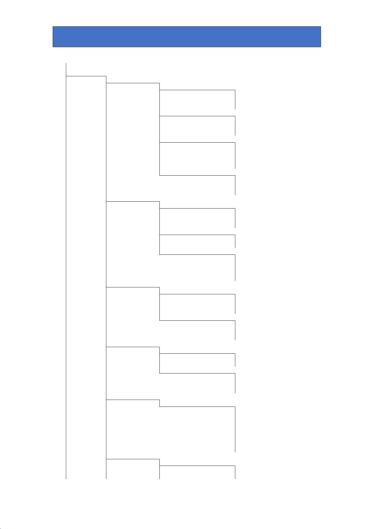
Crystal Vision VisionWeb Control
Chroma Key
Setup
Auto Setup
Sample Setup
Grab
Background
Foreground
Show Samples
Show samples on Main
Show samples on Aux
Freeze Input
Sample Positions
Reset Samples
Sample Select
Horizontal
Vertical
Auto Settings
Reset Chroma Keyer
Auto Lighting
Auto Respill
Gain and Spill
Chroma Key
Min Clip
Max Clip
Acceptance
Foreground
Suppression
Acceptance
Chroma Key Control
Enable
Suppress Foreground
Multiply Foreground
Edges & Key
Invert
Remove
Chroma Key Removal
Black
Greys
White
Edges & Shadows
Edge Processing
Shadow Density
Key Shrink
Hue & Balance
Key Colour Tune
Key Hue
Background Saturation
Balance & Tints
Suppression Hue
Foreground Balance
Lighting
Foreground Tints
Compensation
Lighting Compensation
Enable
Aspect Ratio
Left
Right
Top Bottom
Brightness &
Radial
Contrast
Foreground Adjust
FG Lift
FG Gain
Safire 3 User Manual R1.3 25 24 March 2017
Crystal Vision VisionWeb Control
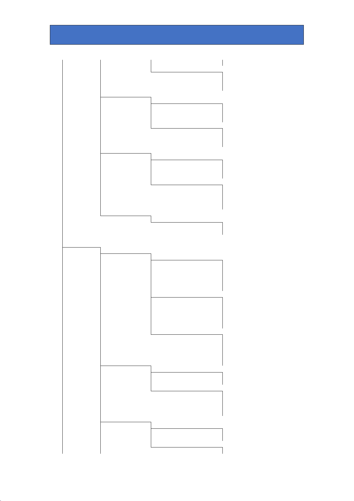
FG Chroma
Background Adjust
BG Lift
BG Gain
FG Colour
BG Chroma
Correct
Foreground RGB Gain
Red
Green
Blue
Foreground RGB Lift
Red Green
Filters &
Blue
Re-spill
Filters
Ring Suppression
Noise Reduction
Edge Softening
Foreground Re-spill
Re-spill enable
Red Green
Output
Blue
Signal
Outputs
Main
Keys
Aux
FG/BG &
Masks
Keys & Masks
External Key Control
Enable
Multiply
Invert
Min Clip
Max Clip
External Mask Control
Enable
Multiply
Invert
Min Clip
Max Clip
Self Key Control
Enable
Multiply
Invert
Min Clip
Internal FG Mask
Max Clip
FG Mask Control
Enable
Invert
FG Mask Window
Left Right
Top
Bottom
Internal BG Mask
BG Mask Control
Enable
Invert
BG Mask Window
Left
Safire 3 User Manual R1.3 26 24 March 2017

Crystal Vision VisionWeb Control
Right
Top
FG/BG Source
Bottom
& Matte
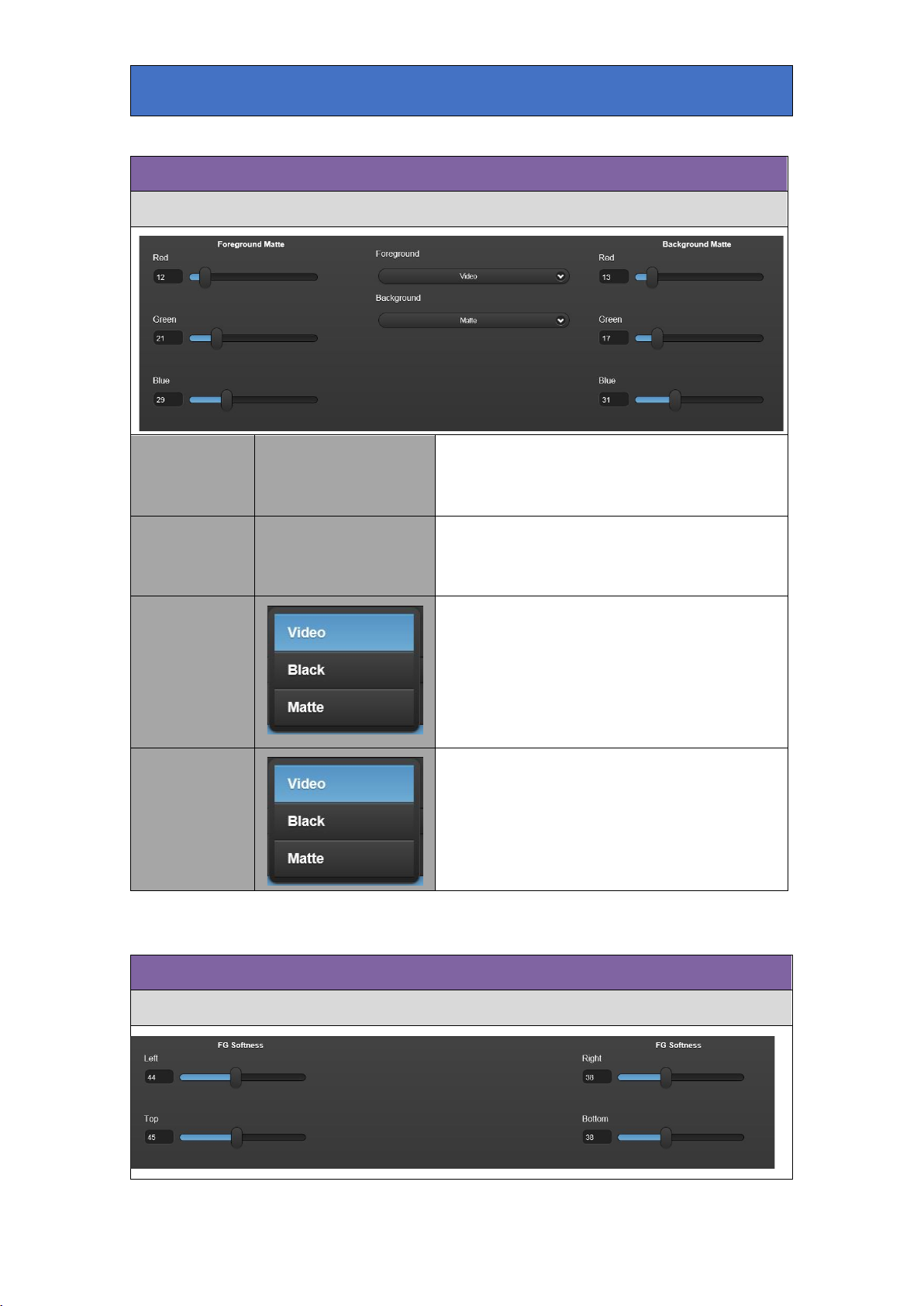
Foreground Matte
Red Green
Blue
Background Matte
Red Green
Blue
FG/BG Source
Foreground
FG Mask
Background
Softness
FG Softness
Left
Right
Top Bottom
BG Mask
Softness
BG Softness
Left
Right
Top Bottom
General
Signal Status
FG Input
Standard
Input Present
Input Black
Input Frozen
Input ATC Present
BG Input
Standard
Input Present
Input Black
Input Frozen
Input ATC Present
Key Input
Standard
Input Present
Input Black
Input Frozen
Input ATC Present
Reference Input
Standard
Input Present
Output
Standard
Input Freeze Enabled
Key Status
Output Faded to Black
Chroma Key
Enabled
Faded Down
Self Key
Enabled
Faded Down
External Key
Enabled
Safire 3 User Manual R1.3 27 24 March 2017
Crystal Vision VisionWeb Control
Faded Down
Masks Enabled
External
FG
BG
Key Fade
Fade Keys
Autotrans
Fades Up
Fades Down
Fade Time
Fade
Fade to Black
Autotrans
Fades Up
Fades Down
Fade Time
Presets
Fade
Presets
Store
Preset Select
Recall
Delay & Timing
Genlock
Source
Reference
Foreground Input Delay
Background Input Delay
Key Input Delay
Short Delay
Output Delay
Pixel Timing
Line Timing
Frame Delays
FG
BG
Key Engineering
Output
Format
Ancillary Data
Invert Output Key
GPI Preset Recall
Enable
GPI Active level
GPI Trigger
GPI Fade Keys
Enable
GPI Active level
GPI Trigger
Progressive Frames
Lock Frames to ATC
Swap FG Input
Swap BG Input
Swap Key Input
Swap Output Frames
Reset
Defaults
Erase Presets
Safire 3 User Manual R1.3 28 24 March 2017
Crystal Vision Control Descriptions
Auto Setup
Set up chroma key auto-sampling. Enable Auto Lighting and Re-Spill. Select the
Compensation'.
7 Control Descriptions
The controls of Safire 3 are accessible from VisionPanel, the VisionWeb Control
software or the board edge. The screen grabs of controls used in this manual are from
VisionPanel but are similar to VisionWeb Control with a few minor differences. The path
to locate controls via VisionWeb Control or board edge follows similar logic. For
instance, in the VisionPanel display, an ‘Input Frozen’ indicator is accessed via the
‘General’ panel, ‘Signal Status’ tab and ‘FG Input’ group where it can also be found
in VisionWeb Control. To find the same control using the card edge follow the path
General->Signal Status->FG Input to the Input Frozen indicator.
VisionWeb GUI controls are located in a number of tabs each containing panels which
mostly contain the controls. Some controls are LEDs that are used to show status,
others are check boxes, buttons or sliders which change various Safire 3 settings.
(Note: Slider controls in VisionWeb Control, once selected, can be moved by the
keyboard up and down arrow keys to give finer control than possible with a mouse.)
The description of the tabs are in the order shown in the GUI i.e.
AUTO SETUP, GAIN & SPILL, EDGES & KEY REMOVE, HUE & BALANCE,
LIGHTING COMPENSATION, BRIGHTNESS & CONTRAST, FG COLOUR
CORRECT, FILTERS & RE-SPILL, OUTPUT SIGNAL, KEYS & MASKS, INTERNAL
FG/BG MASK, FG/BG SOURCE & MATTE, FG/BG MASK SOFTNESS, SIGNAL
STATUS, KEY STATUS, KEY FADE, PRESETS, DELAY & TIMING, ENGINEERING.
Each tab is shown with a screen grab and description of each control’s function:
number and position of samples and grab samples to create a composite image.
Reset Chroma Keyer Return Safire 3 to its calibrated settings.
Auto
Settings
Safire 3 User Manual R1.3 29 24 March 2017
Auto Lighting
Select to automatically compensate for
lighting fade-off towards the edges when
grab samples is selected. See 'Lighting
Crystal Vision Control Descriptions
Select this to freeze the FG input signal.
moving.
Return sample positions to their default
locations.
Select to automatically compensate for
any backdrop colour spill on FG objects
when grab samples is selected. See
Colour Adjust tab->FG Re-Spill.
Set up Safire 3 using FG samples taken
from the backdrop and foreground areas.
The following parameters are
automatically adjusted: Max Clip, Chroma
Key Colour – Hue, Foreground
Suppression – Hue, Acceptance &
Suppression, Chroma Key Tune – Key
Saturation.
Select 1, 5 or 12 samples from the
backdrop area of the FG picture to use for
auto setup. Samples are (optionally)
visible on the main and/or aux outputs
and can be re-positioned. These samples
are used to automatically select optimum
chroma key values to allow for variations
in chroma key backdrop hue and
saturation. Usually the more samples
chosen, the more accurate the result.
Sample
Setup
Auto Re-Spill
Grab
Background
Show
Samples
Sample
Positions
Foreground
Show Samples on Main
Show Samples on Aux
Freeze Input
Horizontal/Vertical
Reset Samples
Select 0,1 or 4 samples from the
foreground area of the FG picture to use
for auto setup. These samples are
(optionally) visible on the main and/or aux
outputs and can be re-positioned as
necessary. These samples are used to
amend the settings of the chroma keyer to
isolate regions in foreground areas that
may cause unwanted keying by forcing
the key signal to zero at these points.
Select this to display the sample positions
as small rectangles on the Main output.
Select this to display the sample positions
as small rectangles on the Aux output.
This is useful to enable accurate
positioning of the backdrop and
foreground samples when the subject is
Adjust the sample's position horizontally
and vertically to the desired location.
Safire 3 User Manual R1.3 30 24 March 2017

Crystal Vision Control Descriptions
Gain & Spill
Manual adjustment of chroma key controls including key clip and gain. Control key
Sample
Select
and FG suppression acceptance angles, and FG suppression gain. Setup chroma key
suppression modes.
Select which sample to re-position – the
selected sample will slowly flash on the
main and/or aux output.
Adjust the offset of the key signal that will cut a hole in
the new Background video signal. Increasing the min
clip value will force lower key levels to zero. This is
mainly used when small amounts of key level remain in
foreground object areas causing breakthrough of the
Chroma Key
Min Clip
Safire 3 User Manual R1.3 31 24 March 2017
new background. Any increase in min clip value will
have to be compensated for by reducing the max clip
value to restore the key in other areas. Note that
shadows and scuffs appear as high to mid level key
values and that increasing the min clip setting and
reducing the max clip setting will tend to accentuate
these. The effect of this control is best observed by
monitoring the Output Key. The default level for this
control is 0.

Crystal Vision Control Descriptions
Adjust the gain of the key signal that will cut a hole in
the new Background video signal. Reducing the max
clip level value will force variations in key level to full
key value by amplifying and clipping. Use this control
Max Clip
Acceptance
to compensate for uneven chroma key backdrop
illumination. Adjusting this control is a compromise
between removing key variations and retaining key
edge detail. The effect of this control is best observed
by monitoring the Output Key. The default level for this
control is 50.
Adjust this control to change the range of colours
about the hue colour (acceptance angle) used by the
new Background key circuitry. Monitor the output key
and with the min and max clip controls set to default
values, adjust this control to give the best overall key.
Note: It may help to invert the key output in the
Engineering menu so that full key level is peak white
and no key is black. Setting the acceptance value too
small may result in an uneven key in the chroma key
backdrop area. Too large a value may cause keying in
foreground areas resulting in the new background
breaking through to the foreground.
Chroma Key
Control
Enable
Suppress
Foreground
Multiply
Foreground
Select this to enable chroma key operation on the
foreground.
Select this to enable FG suppression. This is usually
always selected if 'Multiply Foreground' is NOT
selected. If 'Multiply Foreground' IS selected then
deselecting this option can sometimes give better
results if FG suppression has altered foreground
colours.
Select this to multiply the Foreground by the inverse of
the new Background key. If de-selected, the FG is
added to the keyed background. With good lighting and
a high quality chroma key backdrop it is usually better
to not select 'Multiply Foreground' as FG Suppression
and non-multiply mode give better results particularly
with fine detail such as hair. However sometimes it is
not possible to fully suppress all backdrop detail from
the FG picture and that can show in the final composite.
In this case multiply mode will cut out the backdrop
entirely, but at the expense of fine detail. The different
modes should be tried to see what gives the best result.
Invert
Safire 3 User Manual R1.3 32 24 March 2017
In Multiply Foreground mode this control will invert the
generated key – thereby swapping the FG and BG
pictures in the final composite.

Crystal Vision Control Descriptions
set mid-way to see the effect most clearly.
Edges and Key Remove
Adjust chroma key settings to remove unwanted keying in black, grey or white
Adjust this control to set the suppressed backdrop area
to black. Monitor the keyed FG signal and set the
control to the minimum level necessary to give a solid
black in the chroma key backdrop area. This control is
best adjusted after the hue and acceptance controls
have been set and – because because of their
interactive nature – the min and max clip controls set to
Suppression
Foreground
Acceptance
their default values. Note that when the suppressed FG
signal and keyed Background signal are added together
to form a final composite, any luminance in the FG
backdrop area will be added to the new background.
This can sometimes be compensated for with BG lift
reduction in the BG Match sub menu of the Colour
Adjust tab, but every attempt should be made to
achieve as close to black as possible. Oversuppressing will distort edges possibly causing a black
halo around FG objects.
Adjust this control to change the range of colours
about the hue colour (acceptance window) suppressed
by the Foreground suppression circuitry. Monitor the
Keyed FG signal and adjust this control to entirely
suppress the chroma key backdrop colour. If the
acceptance angle is set too small, then due to
variations in backdrop colour, a colour tint may remain
in places. If the angle is set too large then unwanted
suppression may occur on foreground objects. Adjust
the hue control as well to get the best compromise if
there are large variations in backdrop colour. This
control is best adjusted with the suppression control
areas. Adjust key levels to remove or enhance shadows. Alter key shape to improve
effect.
Safire 3 User Manual R1.3 33 24 March 2017

Crystal Vision Control Descriptions
background.
Use these controls to attenuate the new
Chroma Key
Removal
Black/Greys/White
Edge Processing
background key in foreground areas of black,
grey or white. This is useful where colour spill
from the chroma key backdrop onto foreground
objects are causing unwanted keying of the
Adjust the level of the key in the edge areas.
This control changes the gain of the key at the
edges and other low value areas such as
shadows.
Edges and
Shadows
Shadow Density
Key Shrink
This control changes the appearance of
shadows. Increasing the value of this control
will make shadows appear more prominent and
decreasing less prominent.
Adjust the shape of the key. If a black line
appears around foreground objects when the
new background is added, adjust the key shrink
control to help compensate for this.
Hue and Balance
Manually set the chroma key colour, compensate for under-saturated backdrop
colour and fine-tweak the balance between FG suppression window.
Set the colour that will be used by the new
Background key circuitry. Monitor the output key, and
with the acceptance control set to 90 degrees, and the
Key Colour
Tune
Safire 3 User Manual R1.3 34 24 March 2017
Key Hue
min and max clip controls set to default values, adjust
the control to give the best overall key. Note: it may
help to invert the key output in the Engineering menu
so that full key level is peak white and no key is black.
Note also: this control rarely needs adjusting after
auto setup.

Crystal Vision Control Descriptions
Lighting Compensation
This control helps compensate for a poorly saturated
camera output in FG backdrop areas. Ideally, a well lit
backdrop would produce a 100% saturated colour
Background
Saturation
Suppression
Hue
Balance and
Tints
Foreground
Balance
output from the camera - but this is rarely the case.
While monitoring the output key and with max clip set
to 100, adjust this control to provide an even and low
noise key in the backdrop area. The max clip control
can then be adjusted to amplify the key to full level.
This control is automatically set by quick setup.
Set the colour that will be used by the Foreground
suppression circuitry. Monitor the Keyed FG signal
and adjust this control to suppress the chroma key
backdrop colour. Note that often there is a variation in
backdrop colour caused by lighting etc. so adjust this
control to give the best suppression in the most
noticeable areas. This control is best adjusted with the
suppression control set mid-way and the acceptance
control set to 90 degrees to see the effect most clearly.
Note also: this control rarely needs adjusting after
auto setup.
This control moves the acceptance window of the FG
suppressor circuitry about the selected backdrop hue.
This control is useful when the FG objects contain
colours close to the backdrop colour and so can help
minimise desaturation of some FG colours while
maintaining good backdrop colour suppression.
Foreground
Tints
This control allows areas of the foreground that
contain low saturation levels of the backing colour to
be passed without being suppressed.
Compensate for a poorly lit backdrop.
Safire 3 User Manual R1.3 35 24 March 2017

Crystal Vision Control Descriptions
lighting' is selected in quick setup.
Brightness & Contrast
Adjust the lift and gain of the keyed FG and BG signals to produce a more
realistic composite.
These controls help compensate for uneven backdrop lighting.
By monitoring the output key and adjusting the lighting
Left/Top/Right/Bottom
Radial
compensation controls it is possible to minimise the effects of
lighting edge fade. With max clip set to 100, adjust the position
controls to provide as even a key distribution in the backdrop
area as possible. These controls are automatically set if 'auto
The lighting distribution of a spotlight is a bright centre that
fades away to the edges in a circular pattern. The Background
key produced when a spotlight is used to illuminate a chroma
key backdrop will reflect that lighting distribution. Increasing
key gain (max clip) will help compensate for that but at the
expense of fine detail. By monitoring the output key and
adjusting the lighting compensation controls it is possible to
minimise the effects of lighting edge fade. With max clip set to
100, adjust the radial and control to provide as even a key
distribution in the backdrop area as possible. These controls
are automatically set if 'auto lighting' is selected in quick
setup.
Aspect Ratio
Foreground
Adjust
FG
Lift/Gain/Chroma
Select the aspect ratio of the radial
lighting compensation to match the
image.
These controls modify the FG video signal so it
matches the keyed Background in the final
composite. Monitor the output video and use the lift,
gain and chroma controls to achieve the best
results.
Safire 3 User Manual R1.3 36 24 March 2017

Crystal Vision Control Descriptions
FG Colour Correct
Filters & Re-Spill
Filter FG input for noise and ring removal and soften keyed edges. Add colour tint to
These controls modify the BG video signal so it
matches the keyed Background in the final
Background
Adjust
BG
Lift/Gain/Chroma
RGB Lift and Gain correction of the keyed foreground signal.
composite. Monitor the output video and use the lift,
gain and chroma controls to achieve the best result.
These controls are left untouched by quick setup.
BG lift control can help reduce any luminance added
to the composite by the suppressed FG if some
luminance remains in the FG backdrop areas.
Foreground RGB
Gain
Foreground RGB
Lift
suppressed FG edges to match new background.
These controls adjust the individual red, green and blue gains of
the suppressed FG signal between 80% - 120%.
These controls give positive and negative lift to the individual
red, green and blue channels of the suppressed FG signal.
Safire 3 User Manual R1.3 37 24 March 2017

Crystal Vision Control Descriptions
is selected in quick setup.
Filters
Foreground
Re-Spill
Ring
Suppression
Noise Reduction
Edge Softening
Red/Green/Blue
Enable Enable the Re-Spill feature
This control helps minimise ringing introduced by
the camera.
This control adds a variable amount of filtering to
the Background key signal to help minimise noise
while maintaining fine edge detail.
This control adds a variable amount of filtering to
the Background key signal to smooth jagged edges
caused by high levels of key gain and to minimise
noise.
These controls add a colour tint to the backdrop
spill areas of the suppressed FG picture to
counteract any noticeable colourisation. When an
object is placed in front of a green backdrop, say, it
will experience a green spill around its edges and
reflecting surfaces, but if a blue background (i.e.
sky) was chroma keyed behind, the green spill
would look unnatural. Adding a blue FG re-spill in
this case would produce a more realistic composite.
These controls are automatically set if 'auto re-spill'
Safire 3 User Manual R1.3 38 24 March 2017

Crystal Vision Control Descriptions
Output Signal
Select which signals are routed to the Main
Select video source for Main and Aux outputs.
and Aux video outputs:Output video: the composite chroma keyed
result.
Output key: the key signal, as a
monochrome image, produced by the
combination of the chroma keyer, other
keys and masks.
FG input: the Foreground video input.
BG input: the Background video input.
Key input: the external key input signal.
Outputs
Main/Aux
Keyed FG: the suppressed Foreground
image after chroma keying. This signal is
useful for fine adjustment of the various
controls to optimise the removal of the key
colour from the subject.
Keyed BG: the Background signal after
keying. This signal is useful in fine
adjusting the key gain and other controls.
FG Matte: display the matte colour set by
the keyers and effects/FG source and matte
controls.
BG Matte: display the matte colour set by
the keyers and effects/BG source and
matte controls.
Set clip and gain levels for the External Key, External Mask and Self Key.
Enable all keys, set key operation to Multiply and enable key inversion.
Safire 3 User Manual R1.3 39 24 March 2017
Keys & Masks

Crystal Vision Control Descriptions
outside of the caption fill area.
to the BG signal.
would be disabled if self key mode is enabled.
outside of the caption fill area.
External Key
Control
Min Clip
Max Clip
Enable
Multiply
Invert
Use this control to clip all key signals below the
threshold set by the control – i.e. if the control is set
to 20 then all key levels up to 20% of max will be
removed.
Use this control to amplify and clip all key signals
above the threshold set by the control – i.e. if the
control is set to 80, then all key levels above 80% of
max will be clipped and amplified to full scale.
Select to enable the External Key signal as a key.
The BG picture is keyed and filled with the FG
source. Use this control to key a caption into the
Background video and fill with matte, black or video.
This key augments the chroma key and self key in its
active areas. In chroma key mode this key will force
the FG video to mask chroma keying in unwanted
regions. The external key combines with the self key
to extend the size of the key.
Select to key the FG signal before adding to the
keyed BG signal. Select if the FG signal is not black
Select to invert the clipped key.
External Mask
Control
Self Key
Control
Enable
Multiply
All other
controls
Enable
Multiply
Select to enable the external key signal as a mask.
The mask signal disables the self key and chroma
key in its active areas. If the chroma key is enabled
the mask will force the final composite to
Background and this can be used to compensate for
missing backdrop areas or to promote an area of
Background to the front of the composite.
Multiply mode is the normal way of using the
external mask; the suppressed FG signal is keyed
with the mask prior to adding to the BG. In nonmultiply mode the FG signal is not keyed and added
As External Mask.
Select to use the luminance of the FG signal as a
key. The BG is keyed and filled with the FG source.
Use this control to key a caption derived from the FG
video into the Background video and fill with a
matte, black or video. Usually chroma key mode
Select to key the FG signal before adding to the
keyed BG signal. Select if the FG signal is not black
All other
controls
Safire 3 User Manual R1.3 40 24 March 2017
As External Mask.
Crystal Vision Control Descriptions
Internal FG Mask
edges.
Internal BG Mask
Enable and set rectangle size for internal FG mask.
Left/Top/Right/Bottom Use these controls to position the mask rectangle.
Select this control to enable the FG mask. This user-
Enable
positionable mask will override the chroma key in its active
area to force the BG signal. Use this mask if the chroma
key backdrop is too small or damaged, or badly lit at the
Invert Select this control to invert the mask.
Enable and set rectangle size for internal BG mask.
Left/Top/Right/Bottom Use these controls to position the mask rectangle.
Select this control to enable the BG mask. This userpositionable mask will override the chroma key in its active
Enable
area to force FG video. Use this mask to disable the chroma
key in FG non-backdrop areas containing the key colour, or
reflective objects. Note that the BG mask does not override
FG suppression, only the BG key.
Invert Select this control to invert the mask.
Safire 3 User Manual R1.3 41 24 March 2017
Crystal Vision Control Descriptions
FG/BG Source & Matte
FG Mask Softness
Set FG and BG matte colour. Select FG and BG video sources.
Foreground
Matte
Background
Matte
Foreground
Background
Red/Green/Blue
Red/Green/Blue
Use these controls to set the colour of the
FG matte that will be used when the FG
source is set to ‘matte’.
Use these controls to set the colour of the
BG matte that will be used when the BG
source is set to ‘matte’.
Use these controls to select the source of the
FG signal. Select either video, black or the
colour matte – usually video for chroma
keying.
Use these controls to select the source of the
BG signal. Select either video, black or the
colour matte – usually video for chroma
keying.
Set the amount of softness for each edge of the FG mask rectangle.
Safire 3 User Manual R1.3 42 24 March 2017

Crystal Vision Control Descriptions
BG Mask Softness
Signal Status
Use these controls to soften the four edges of
FG
Softness
Left/Top/Right/Bottom
Set the amount of softness for each edge of the BG mask rectangle.
the mask to make the mask less noticeable.
The internal masks can be configured and
positioned as a rectangular wipe and added
softness can be used as an artistic effect.
BG
Softness
Left/Top/Right/Bottom
Monitor the status of all inputs and outputs.
Use these controls to soften the four edges of
the mask to make the mask less noticeable.
The internal masks can be configured and
positioned as a rectangular wipe and added
softness can be used as an artistic effect.
Shows input video standard i.e
Standard
FG /BG/ Key Input
Input Present Lights green if input video present.
Safire 3 User Manual R1.3 43 24 March 2017
“1920x1080/50i” or “missing” if none
detected.
Crystal Vision Control Descriptions
detected.
Key Status
Reference Input
Output
Input Black
Input Frozen Lights yellow if input video frozen.
Input ATC Present
Standard
Input Present
Standard
Input Freeze
Enabled
Output Faded to
Black.
Lights yellow if input video at black
level.
Lights green if audio timecode is
detected.
Shows input video reference standard
i.e “1080/50i” or “missing” if none
Lights green if reference video
present.
Shows output video standard i.e
1920x1080/50i”.
Lights yellow if FG input freeze
selected in ‘Auto Setup’.
Lights yellow if output faded to black
in ‘Key Fade’.
Monitor the status of Chroma Key, External Key, Self Key and External Mask.
Chroma/Self/External
Key
Masks Enabled
Enabled Lights yellow if key is enabled.
Faded Down Lights yellow if key is faded down.
External
FG
BG
Lights yellow if External mask
enabled in ‘Keys & Mask’.
Lights yellow if FG mask enabled in
‘Internal FG Mask’.
Lights yellow if BG mask enabled in
‘Internal BG Mask’.
Safire 3 User Manual R1.3 44 24 March 2017

Crystal Vision Control Descriptions
Key Fade
fade time of 0-100 seconds.
outputs to and from black.
Fade all keys up and down – fade outputs to and from black.
Fade Keys
Fade to Black
Fade Time
Fade
Auto Trans
Fades Up/Down
Fade Time
Fade
Auto Trans.
Use this control to set an autotrans
fade time of 0-100 seconds.
Use this control to manually fade keys
up and down.
Use this control to automatically fade
enabled keys up and down at the rate
set by the Fade Time control. In
chroma key mode the FG image will
be faded up and down but masks are
unaffected. External and self key will
fade up and down.
These indicate which direction the
autotrans operation will take.
Use this control to set an autotrans
Use this control to manually fade
Use this control to automatically fade
main and aux outputs to and from
black at the rate set by the Fade Time
control.
Safire 3 User Manual R1.3 45 24 March 2017
Fades Up/Down
These indicate which direction the
autotrans operation will take.
Crystal Vision Control Descriptions
Presets
Delay & Timing
Select which preset memories to save to or recall from.
Store Store Safire 3 settings as one of 40 presets.
Preset Select
Recall Recall one of 40 previously stored settings.
Select genlock source, output timing with respect to reference and video delays for all
inputs.
Select preset number 1-40 to store or recall.
Pixel Timing
Output Delay
Line Timing
Safire 3 User Manual R1.3 46 24 March 2017
Delay output video horizontally by 0 to 2640 pixels
with respect to reference. (See note below.)
Delay output video vertically by 0 to 1125 lines
with respect to reference. See note above for max
delay. Note: the total Pixel + Line delay cannot
exceed one frame for any output standard. E.g.
720 lines is the maximum delay for 720p standard.

Crystal Vision Control Descriptions
Select whether the external
Select this to disable the Noise Reduction and
Engineering
Source
Reference
Genlock
Foreground,
Background,
Key, Input Delay
Short Delay
Frame Delays FG/BG/Key Delay
Select which input Safire 3 will
use as its reference source.
analogue reference input is
Tri-Level or Black & Burst. No
reference needs to be applied
unless 'Reference' is selected
as the genlock source.
Indicates whether the output signal is more than
one whole frame delayed with respect to each
input.
Edge Softening filters to minimise propagation
delay. Short Delay for SD = 85uS, HD = 18uS, 3G =
10uS. Without Short Delay selected, add 5 lines
delay to the above values.
These controls delay the selected signal by up to
ten frames at the Safire 3's input frame
synchroniser.
Control Engineering functions such as Ancillary data, GPI preset recall, GPI fade
keys, swap field sequences and reset Safire 3.
Select which input video should be
Output Format
used as the format for the video
output.
Safire 3 User Manual R1.3 47 24 March 2017

Crystal Vision Control Descriptions
Select to enable recall of presets
GPI.
GPI Preset
Recall
Ancillary
Data
Invert Output Key
GPI Active
Level
GPI Trigger
Enable
Select which video input is the
source of output ancillary data, or
blank it.
Select this to invert the output key.
Use this to match the key polarity
with other equipment or for
monitoring purposes to make the
key more visible.
by GPI. Presets 1-32 can be
selected from the binary coding of
the external GPI inputs.
Select low or high level as the
active level for the GPI.
Select whether GPI recall should
be triggered by a change in level or
a pulse.
GPI Fade
Keys
Progressive
Frames
Enable
GPI Active
Level
GPI Trigger
Lock Frames to ATC
Swap FG/BG/Key Input
Swap Output frames
Select to enable fading of keys by
Select low or high level as the
active level for the GPI.
Select whether GPI triggering
should be triggered by a
permanent change in level or a
transition.
Lock the HD progressive video
output to Ancillary Timecode.
Swap field sequence of the
selected progressive video input.
Swap field sequence of the
progressive video output.
Safire 3 User Manual R1.3 48 24 March 2017

Crystal Vision Control Descriptions
Reset
Defaults
Erase Presets
Select to restore Safire 3 to default
conditions without erasing stored
presets.
Select to restore Safire 3 to default
conditions AND erase stored
presets.
Safire 3 User Manual R1.3 49 24 March 2017
Crystal Vision Using Safire 3
8 Using Safire 3
In this section, when we refer to ‘FG’ and ‘BG’ we are referring to the FG and BG
input video signals. FG is the signal with objects placed in front of a coloured
backdrop. BG is the signal that will replace the coloured backdrop in the final
composite. Whereas, to avoid confusion, ‘foreground’ and ’backdrop’ refers to
parts of the FG image.
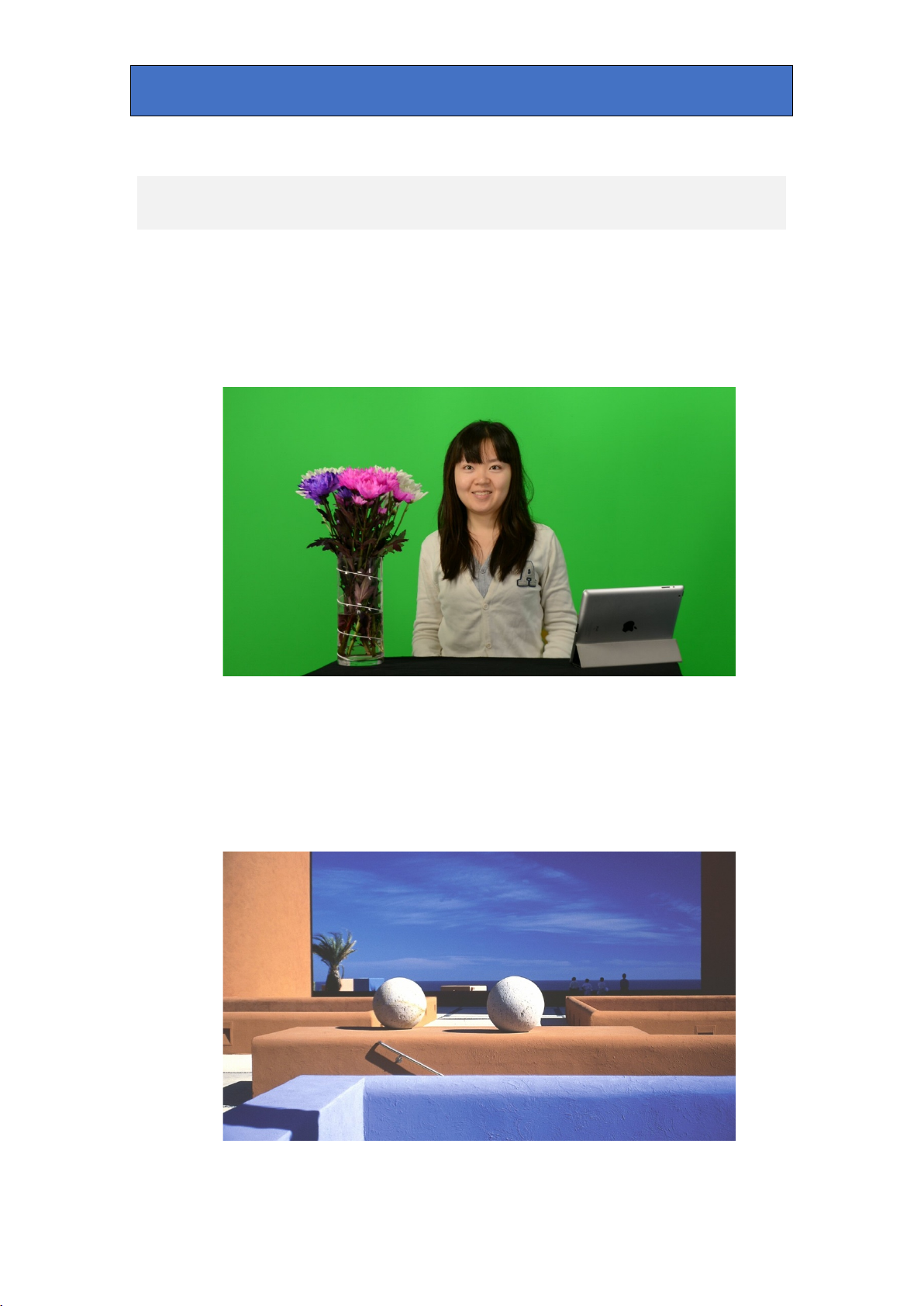
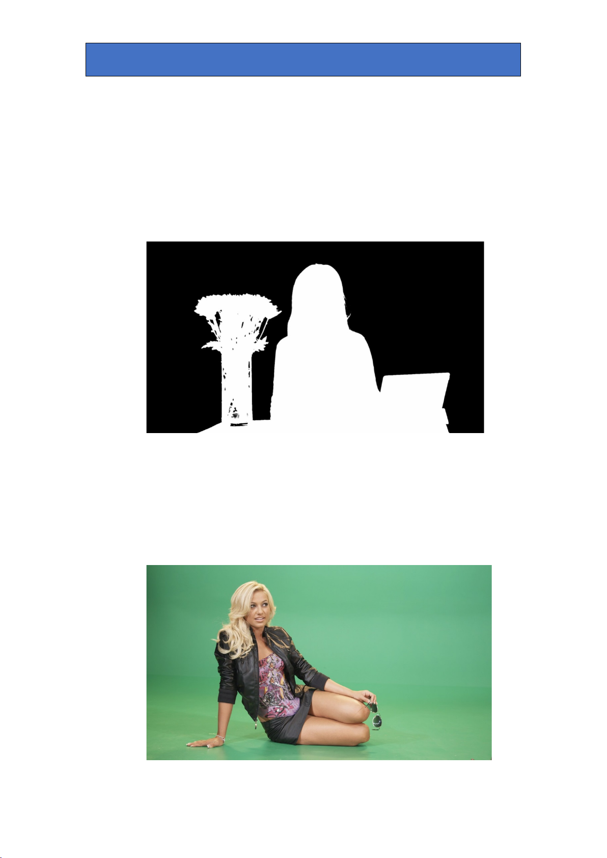
Here is an example of a FG image:
The model is sitting in front of a green backdrop. The backdrop can be of any
uniform colour provided the foreground objects don’t contain exactly the same
colour. The backdrop must be well and uniformly lit and the foreground objects
placed at least 2m in front to reduce colour tinting from backdrop reflections (see
section - Chroma Key Tips).
The BG image will appear behind the foreground objects in place of the
backdrop. Here is an example of a BG picture:
Safire 3 User Manual R1.3 50 24 March 2017

Crystal Vision Using Safire 3
With Suppress Foreground in the Gain & Spill menu selected, the chosen hue
set by the Suppression Hue control in the Hue & Balance menu is subtracted
from the FG signal to replace the backdrop colour with black:
Above, the green backdrop has been replaced by black and other foreground
colours remain largely unaffected. A similar process is used to create a ‘key’ to
cut a hole in the BG signal. In this case the Key Hue control in the Hue &
Balance menu sets the key colour:
The two images are then added together to create a high-quality composite:
Safire 3 User Manual R1.3 51 24 March 2017

Crystal Vision Using Safire 3
If Multiply Foreground is selected, the FG signal is keyed before adding to the
keyed BG. Normally this is left de-selected but can be used if it otherwise proves
impossible to create a realistic effect. In this mode, Suppress Foreground’ can
still be selected to suppress any colour tinting on foreground objects.
Selecting ‘Suppress Foreground’ and de-selecting ‘Multiply Foreground’
helps retain fine foreground detail and generally gives the most realistic
results with a well-lit backdrop.
Safire 3 is capable of producing a very realistic composite chroma key image, but
to get the best results, attention must be paid to the lighting and quality of the
coloured backdrop, the lighting of the foreground objects and colour and
reflectivity of foreground objects. If all of the above have been considered, then
the Auto Setup feature of Safire 3 will give excellent results.
Auto Setup
For most well lit scenes, Auto Setup provides an acceptable chroma keyed
result. Not all of Safire 3’s controls are adjusted automatically so some
knowledge of the other controls is essential. Each control is explained in detail in
the ‘Controls’ section but the following brief explanation with pictorial examples
will help aid understanding.
Auto Setup works by using up to 12 samples from the backdrop area and up to
four samples of the foreground to automatically adjust most of Safire 3’s settings
to achieve the best result by taking into account variations in illumination and
saturation. Auto Setup allows the number and position of samples to be adjusted
and it also offers the option of freezing the FG input video to make positioning the
samples easier.
In the above example, the 12 grab samples can be seen distributed around the
model. With perfect lighting, only one sample might be necessary. In this example
no foreground samples were used and the Auto Lighting and Auto Re-Spill
options were selected. Auto Lighting compensates for variations in lighting
intensity across the backdrop, and Auto Re-Spill replaces any backdrop colour
that may be reflected onto foreground objects with another more realistic colour
derived from the BG signal.
Safire 3 User Manual R1.3 52 24 March 2017

Crystal Vision Using Safire 3
The Grab Samples control automatically produced the following composite
image:
Here we can see a realistic result; notice that hair detail and glass transparency
has been retained. No foreground samples were necessary here but would be
used if small amounts of BG image broke through to the foreground. Selecting
foreground samples will automatically adjust the key Min Clip setting to force the
key to zero at these points. Not all FG images are as well lit as the above
example and it may be necessary to fine tune Safire 3’s settings after Auto Setup.
Foreground Suppression
Safire 3 works by suppressing the colours of foreground objects within a range of
hues set by a combination of the Suppression Hue control in the Hue & Balance
menu and the Foreground Acceptance control in the Gain & Spill menu.
Foreground colours that are exactly the same as the selected hue are
suppressed to black and other colours close to that are suppressed to varying
shades of grey. The Foreground Suppression control in the Gain & Spill menu
adjusts the result to provide an even black backdrop – this control is set
automatically by Auto Setup. The following picture shows the Keyed FG output
where all the backdrop area has been suppressed to black prior to adding to the
keyed BG signal.
Safire 3 User Manual R1.3 53 24 March 2017

Crystal Vision Using Safire 3
If we manually adjust the FGS Suppression control away from ideal to show a
grey backdrop, it shows more clearly the effects of colour suppression. In the next
picture you can see residual green backdrop colour around the model’s hair – this
is because the FGS Acceptance control, which adjusts the range of colours that
are suppressed, has been set at too narrow an angle.
This control is set automatically by Auto Setup but may need adjusting for best
results. In the next picture the FGS Acceptance control has been set at too large
an angle and has noticeably changed the colour of the leaves of the flowers in the
vase.
Adjustment of the FGS Acceptance control is a compromise between removing
residual backdrop colour and leaving wanted foreground colours unaffected.
Safire 3 User Manual R1.3 54 24 March 2017

Crystal Vision Using Safire 3
Another example in the picture below shows the model wearing a top of similar
colour to the blue backdrop:
Auto Setup without a foreground sample produces the following result:
Some key remains, which causes the BG signal to be visible on foreground areas
– but with a single foreground sample the Min Clip control is automatically
adjusted to resolve this:
Safire 3 User Manual R1.3 55 24 March 2017

Crystal Vision Using Safire 3
Notice how the model’s top now appears purple as suppression has removed
some blue from it, but this can be improved by minimising the FG Acceptance
angle:
This an area where Multiply Foreground mode can sometimes be
advantageous. De-selecting Suppress Foreground ensures that there can be no
colour change to foreground objects of similar colour to the backdrop.
Background Key
The key that cuts the hole in the new BG is derived from Key Hue in the Hue &
Balance menu and Chroma Key Acceptance in the Gain & Spill menu, and
modified by the Chroma Key controls, Min Clip and Max Clip. The Key Hue and
Acceptance controls are independent of those that produce Foreground
suppression and are automatically set by Auto Setup, but may need adjusting.
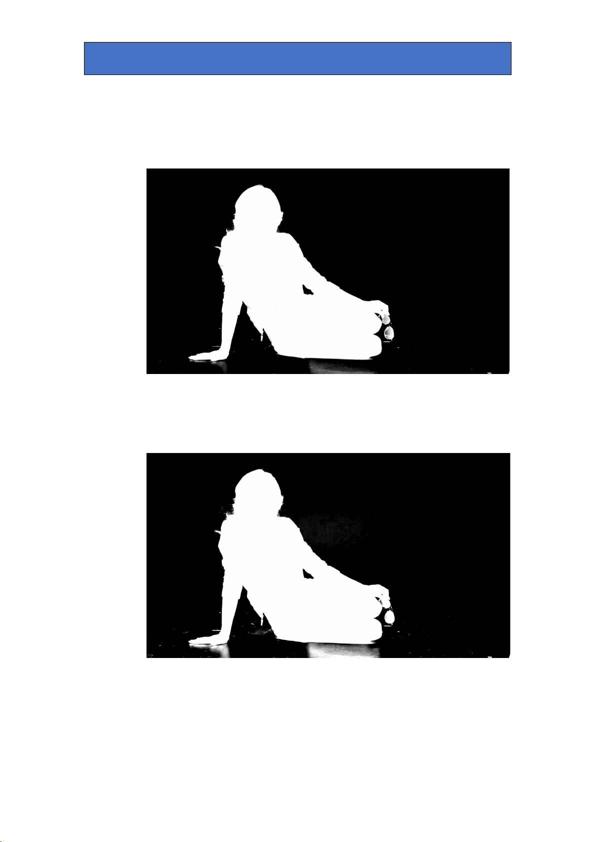
The following picture is the Output Key signal produced by Auto Setup. This is the
level of quality of key to aim for: solid blacks and whites with no noise and fine
detail retained.
.
Safire 3 User Manual R1.3 56 24 March 2017
Crystal Vision Using Safire 3
The Chroma Key Gain (CKG) Min Clip and Max Clip controls are used to clip the
key at its minimum and maximum levels. Both these controls are set
automatically by Auto Setup but may need adjusting. Min Clip is mainly used to
reduce any small amounts of key level in foreground object areas causing
breakthrough of the BG picture. Increasing the Min Clip value will force lower key
levels to zero. Shadows can also be accentuated by raising Min Clip.
Max Clip is used to increase the overall gain of the key signal, removing
variations to give an even result. The following picture is the Output Key with Max
Clip set to a low value – although there are no variations in key in backdrop
areas, fine hair detail has been lost. Set Max Clip to as high a value as possible.
Low values of Max Clip also change the shape of the key causing edges to be
more noticeable in the composite output.
Additional Controls
To illustrate more advanced Safire 3 features it is necessary to use a more
challenging FG signal. The backdrop is unevenly lit and has shadows and
reflections that may or may not be wanted. The model is also wearing a shiny
black jacket that tends to reflect and cause an unwanted key.
Safire 3 User Manual R1.3 57 24 March 2017

Crystal Vision Using Safire 3
Auto Setup produces a key with signs of breakthrough in the black jacket and
skirt. The reflective floor is also producing a key. The Key Output in the picture
below shows unwanted keying in the model’s jacket:
To illustrate the importance of good lighting and backdrop quality, in the following
picture the Max Clip value has been deliberately raised above the Auto Setup
value to show the raw key signal:
The variations in backdrop illumination can clearly be seen, as can scuff marks
on the floor.
Should Auto Setup fail to produce a satisfactory result, these imperfections can
be minimised by manually adjusting the key gain controls:
With Max Clip set to zero and Max Clip set to 40, adjust the Background
Saturation control in the Hue & Balance menu to give as best a ‘noise’ free key
signal possible – aim for consistent greys.
Now adjust Min Clip sparingly to remove any residual key noise.
Safire 3 User Manual R1.3 58 24 March 2017
Crystal Vision Using Safire 3
The Chroma Key Removal tools in the Edges & Key Remove menu allows key
to be removed from areas where the foreground picture is black, grey or white.
Slightly adjusting the Greys control removes the key from the jacket. The Max
Clip control will need adjusting to compensate. The following picture shows the
improved Key Output after Chroma Key Removal:
Notice that the floor reflections still remain in the key signal. Increasing key gain
by reducing the Max Clip value will certainly remove the keying in the floor area
but at the expense of key quality. Increasing the Min Clip value will have the
opposite effect by emphasising low key levels. The following picture shows just
that:
The key on the floor area has been exaggerated. This can be useful when
shadows need to be emphasised, but not in this case. The Shadow Density
control in the Edges & Key Remove menu changes the density of the key signal
in shadow areas to enhance or reduce shadows:
Safire 3 User Manual R1.3 59 24 March 2017
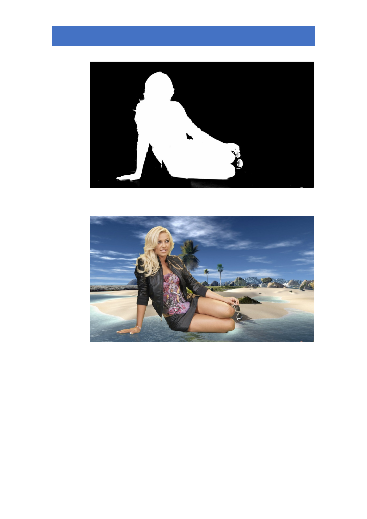
Crystal Vision Using Safire 3
The final composite shows a realistic scene with shadows removed and some
fine hair detail remaining:
Even better results can be obtained with careful lighting and non-reflecting and
unmarked backdrop surfaces.
Re-Spill
Spill is the effect where backdrop colour appears on the foreground objects
usually by reflection off skin or clothes. This can make foreground objects appear
unnatural when chroma keyed over a different colour background. The Re-Spill
controls in the Filters & Re-spill menu add a colour tint to those foreground
objects containing some residual backdrop colour. Auto Re-Spill uses the same
sample positions to sample the BG image as is used for the FG.
Safire 3 User Manual R1.3 60 24 March 2017
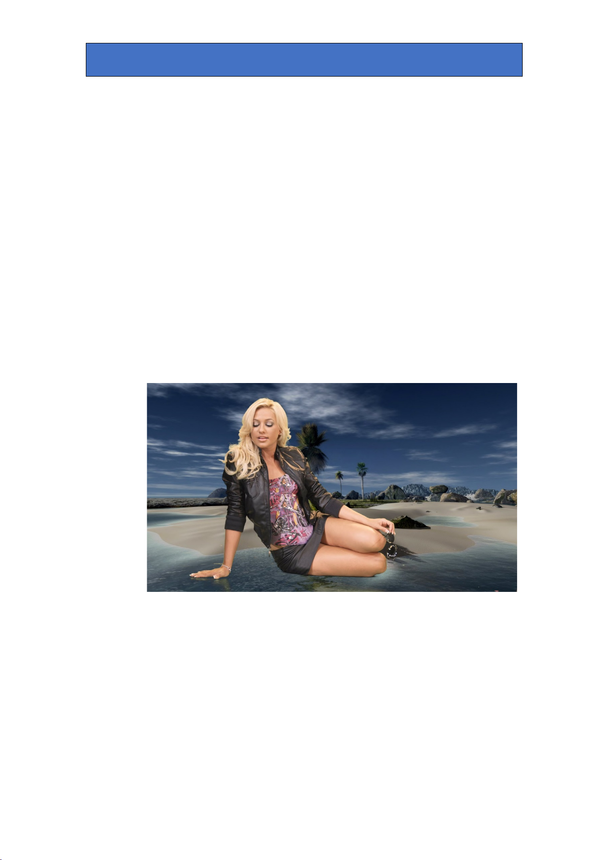
Crystal Vision Using Safire 3
Foreground Tints
If the foreground objects contain similar colours to the backdrop colour there is a
likelihood of those colours being de-saturated by the suppression process. The
FG Acceptance window control can be narrowed to minimise this effect but
sometimes a wider acceptance angle is necessary to suppress all the backdrop
colour. In that case the Foregrounds Tints control in the Hue & Balance menu
can add colour back to the suppressed FG.
Lighting Compensation
The light output from a studio light often fades towards the edges which results in
a non-uniform key signal requiring more key gain to even it out. The Lighting
Compensation controls in the Lighting Compensation menu boost the key at the
edges, or radially. Auto Setup will automatically adjust these controls if enabled.
Colour Adjust
In the Brightness & Contrast menu, Safire 3 has controls that enable the final
composite image to be as realistic as possible. These include individual Lift, Gain
and Chroma level control of both FG and BG signals. Also available in the
Foreground Colour Correct menu are FG RGB Gain/Lift controls. Here the BG
has been darkened and the FG red gain increased slightly to give a sunset feel:
Keys and Masks
See section - ‘Key Signals’ for more information on how keys and masks
combine.
In addition to chroma keying, Safire 3 can generate an internal linear self key
derived from the luminance of the FG signal. Enabled in the Keys & Mask menu,
this can be used to key a caption into the background video and fill with a matte,
black or video. In the picture below the Crystal Vision logo signal is the FG input
and is self keyed into the BG signal using the FG signal as both key and fill.
(Note: The model in front of the green backdrop is the BG signal in this setup).
Safire 3 User Manual R1.3 61 24 March 2017

Crystal Vision Using Safire 3
The Self Key, Max Clip and Min Clip controls are adjusted to give the best result.
In the picture below with a different BG and key signal, Matte is selected as the
FG key fill in the FG/BG Source & Matte menu.
External Key
The External Key input can be used as a linear key to cut a hole into the BG
signal. Logos often have two separately generated components – a key and a fill.
To create the picture below, the model in front of the green backdrop is the BG
signal, the logo key signal is fed to the External Key input and the logo fill signal
to the FG input:
Safire 3 User Manual R1.3 62 24 March 2017

Crystal Vision Using Safire 3
The External Key can also be used as a FG force signal during chroma keying to
prevent unwanted keying on foreground objects. In the example below, the
chroma keyer has been set to key off the pitch colour in Multiply Foreground
mode. The logo signal here is both the External Key input and BG signal. The
logo needs to appear as though it is painted onto the pitch with players
apparently able to walk over it, and it is possible to combine the chroma key and
External Key to limit chroma keying to the External Key area only:
Because, in this case, the key and fill signals are the same signal, the External
Key Inversion control needs selecting to disable chroma keying in the non-logo
key areas by forcing the FG signal (See Section – Key Signals). Below is the Key
Output:
Safire 3 User Manual R1.3 63 24 March 2017
Crystal Vision Using Safire 3
The white outline of players and spectators produced by the chroma key can be
seen, but note that there is no other chroma keying outside of the logo key area.
The External Key can also be used to prevent unwanted keying on foreground
objects during normal studio chroma key operation. For example, if the
foreground contained an object of exactly the same colour as the backdrop, or a
highly reflective object was causing unwanted keying, then a well placed key
could be input to prevent this.
External Mask
During chroma keying, the External Mask combines with the chroma key to force
the BG signal. In the following example, an External Key input signal is selected
as External Mask:
The External Mask signal combines with the key produced by the chroma keyer,
as can be seen in the following Key Output:
Safire 3 User Manual R1.3 64 24 March 2017

Crystal Vision Using Safire 3
The result is that the BG signal appears to be in front of the FG image:
This technique is commonly used to promote architectural features such as pillars
from the background to the foreground so actors appear to be walking behind
them.
Internal Masks
Safire 3 has two independent internal rectangular mask generators to remove
unwanted foreground keying and to force keying in areas where the backdrop is
too small or badly illuminated. These masks can be re-sized, inverted or not and
moved to the ideal position. The following are examples of where FG and BG
mask generators could be useful:
Safire 3 User Manual R1.3 65 24 March 2017

Crystal Vision Using Safire 3
In this example the backdrop is torn either side and features a discoloured patch.
Without the FG Mask the tears are clearly visible. The patch can be keyed out by
widening the FG Acceptance window control and adjusting the key controls:
With the FG Mask, the left hand side and some of the right hand side tears are
removed by correct positioning of the FG Mask rectangle:
Safire 3 User Manual R1.3 66 24 March 2017

Crystal Vision Using Safire 3
As part of the right hand side tear is within the wanted foreground image area it
cannot be totally masked without losing some part of the foreground. To remove
this entirely would require an external key signal set up as a mask. The second
example shows the FG model wearing a badge of identical colour to the
backdrop. Normally this would cause an unavoidable key.
After chroma keying the BG image can be seen in the badge:
Using the BG Mask controls, a rectangle can be placed over the badge to disable
keying in that area. Note that FG suppression would still be acting, so the chroma
keyer must be set to Multiply Foreground mode to retain the original colour:
Safire 3 User Manual R1.3 67 24 March 2017

Crystal Vision Key Signals
9 Key Signals
All the keys in Safire 3 combine to form a single key which is used to cut a hole in
the BG picture. The keys combine as a logical ‘OR’ such that high level (white)
areas take priority. All keys can be individually inverted from VisionWeb or
VisionPanel.
The following is a pictorial description of key polarities for common Safire 3 key
operations. The White (high level key) is the part of the key signal that will show
the FG picture and Black (low level key) the BG picture.
Chroma key
Generated by Safire 3 to cut a hole in the BG signal. The white areas will show
the selected FG source, usually the suppressed or keyed FG picture:
Self Key
To cut a caption derived from the FG signal into the BG and fill with same FG
video, matte or black:
Safire 3 User Manual R1.3 68 24 March 2017

Crystal Vision Key Signals
External Key
To cut a caption using the external key input into the BG signal and fill with FG
video, matte or black:
To force the FG picture to override the chroma key:
This key shape would limit chroma keying to the black area only and force the FG
picture to stay unaffected in the white areas.
Safire 3 User Manual R1.3 69 24 March 2017

Crystal Vision Key Signals
External Mask
The External Key input when used as an External Mask combines with the other
keys as a logical ‘AND’ such that black areas take priority.
To force the BG picture to override the chroma key using the external key input
as a mask:
The mask signal above combines with the chroma key to force the composite to
BG in the black areas:
Or to override the chroma key in areas where the backdrop is missing, damaged
or poorly lit – typically the edges:
Safire 3 User Manual R1.3 70 24 March 2017

Crystal Vision Chroma Key Tips
10 Chroma Key Tips
Lighting
Proper set lighting is essential for realistic chroma keying and can help to
minimise the amount of time required to set up Safire 3.
The coloured backdrop must be as evenly illuminated as possible over its entire
useable surface. Variations in lighting cause chroma key level variations which
require extra key gain to remove. As key gain is increased, the shape of the key
edges change making the composite result less realistic. Lighting Compensation
controls can help minimise the effects of uneven lighting.
Wherever possible use the same type of lighting on the backdrop – all tungsten,
all LED etc. Try to avoid mixing light types as they have different colour
temperatures and will produce a variable key signal.
The lighting on the backdrop should be diffused and as low level as possible to
minimise spill – that is the reflection of the backdrop colour onto the foreground –
but bright enough to produce a low-noise camera output. Ideally, the backdrop
lighting should have roughly the same incident light level as the subject’s key
light.
Subject Placement
To minimise spill, the foreground subjects should be as far away as possible from
the backdrop, at least 2m. This may not be possible with weather maps, for
example, but some lighting techniques can minimise the effect of spill: up or down
lighting the vulnerable areas with white light can help, as can using a gel of a
complementary colour – i.e. a magenta gel when using a green backdrop.
Background
The backdrop itself should be of a consistent quality: scuff marks, patches etc.
also require increased key gain. Use an internal or external mask signal to force
the composite to BG in difficult areas.
The backdrop should be of a non-reflective nature as should the floor surface. It
is very difficult to avoid keying on foreground reflections from a shiny floor.
Clothing
The colour of foreground objects should be chosen to be dissimilar, wherever
possible, to the backdrop colour. Narrowing the acceptance angle to avoid keying
on foreground objects makes it harder to achieve a good key on variations in
backdrop colour.
Reflective Foreground Objects
Any Foreground object that is reflective may reflect some of the backdrop colour
causing unwanted keying. Use the internal BG mask or external key to prevent
keying on glass table tops etc. unless wanted, but consider that natural
reflections often mirror image the reflected scene.
Safire 3 User Manual R1.3 71 24 March 2017

Crystal Vision Troubleshooting
information
Check that a valid SDI input is present and that any cabling is intact
Check that the input SDI stability is within normal limits
If necessary reset the card
retained, use a factory reset to erase any configurations stored in the card
11 Troubleshooting
Card edge monitoring
The front edge of the card provides useful power rail monitoring and input status.
Safire 3 front edge view
See Card Edge Controls for explanation of card edge LEDs.
The card edge LEDs and 10-digit display may be used in conjunction with status
information from any connected remote status panel display or from Statesman if
available.
Basic fault finding guide
The Power OK LEDs are not illuminated
Check that the frame PSU is functioning – refer to the appropriate frame manual for detailed
There is no video output
The video output exhibits jitter
The card no longer responds to front panel control
Check that the card is seated correctly and that the Power OK LEDs are lit
Check any active control panel cabling
Check if the control panel can control another card in the same rack
Resetting the card
If required, the card may be reset by removing the card from the rack and then re-inserting it
It is safe to re-insert the card whilst the rack is powered. Any previous configuration will be
Safire 3 User Manual R1.3 72 24 March 2017

Crystal Vision Specification
12 Specification
Safire 3
General
Inputs
Outputs
Dimensions
Weight
Power
consumption
Video
Video
standards
supported
Delay through
board
100mm x 266mm module with DIN 41612 connector.
200g.
11.9 Watts.
HD or SD SDI 270 Mb/s to 2.970 Gb/s serial digital compliant to EBU
3267-E, SMPTE 259, SMPTE 292-1 and SMPTE 424/425-A.
Cable Equalisation:
3G (2.970Gb/s) – 80 metres, Belden 1694A or equivalent.
HD (1.485Gb/s) – 140 metres, Belden 1694A or equivalent.
SD (270Mb/s) >250 metres, Belden 8281A or equivalent.
Automatic de-embedding to SMPTE 272M or SMPTE 299M.
625i, 525i, 720p50, 720p59.94, 720p60, 1080i50, 1080i59.94, 1080i60,
1080p23.98, 1080p24, 1080p25, 1080p29.97, 1080p30, 1080p50,
1080p59.94, 1080p60, 1080PsF23.98, 1080PsF24, 1080PsF25,
1080PsF29.97, 1080PsF30, 2048x1080p23.98*, 2048x1080p24*,
2048x1080p25*, 2048x1080p29.97*, 2048x1080p30*,
2048x1080PsF23.98*, 2048x1080PsF24*, 2048x1080PsF25*,
2048x1080PsF29.97*, 2048x1080PsF30* (*= YUV 4:2:2 10 bit).
Input format auto selected.
Selectable ten frame video delay on all inputs can be used to
compensate for delays in graphic generators. Minimum delay with Short
Delay ‘ON’: SD=85uS, HD=18uS, 3G=10uS. Short Delay Mode ‘OFF’:
as for ‘ON’, but plus five video lines.
Video
Rear Module I/O
RM50 Three serial video inputs, one analogue sync input. Two BNC video
Safire 3 User Manual R1.3 73 24 March 2017
Serial output: 270Mb/s to 2.970Gb/s serial compliant to EBU 3267-E,
SMPTE 259, SMPTE 292-1 and SMPTE 424/425-A.
Output follows the input format.
Audio is embedded to SMPTE 272M or SMPTE 299M.
outputs.

Crystal Vision Specification
Remote:
Control from VisionWeb Control web browser software.
Connectors:
RJ45 Ethernet connection.
Power
9v dc external mains power supply, 100-240Vac.50/60Hz 1A.
Three serial video inputs, one analogue sync input. Two BNC video
RM73
outputs – Main Output relay bypassed in the event of power failure.
Status monitoring
LEDs
GPI inputs
Number and type:
GPI outputs
Number and type:
Input fail output
Type:
Control
Front of card edge LED indicators to indicate:
PSU rails present.
SDI input HD/SD.
6 x GPI inputs. For recall of 32 presets and trigger of auto key transition.
Active pull to ground, pulled up to +5V through 10 kohm.
Pulse mode GPI to be asserted for min. of 40mS and at least 2mS
before vertical interval.
None.
Dark Blue.
General
Control
Dimensions:
Control from VisionPanel 3U touch screen control panel.
SNMP control and monitoring via frame CPU and Ethernet connection.
VisionPanel
3U touch screen. 344mm wide, 133.5mm high (3U), 44mm deep (rear
connector to mounting plate); 65mm deep (rear connector to display
bezel). Weight 1.64kg without stand; 1.97kg with stand.
USB2 x 2
DC power connector.
Safire 3 User Manual R1.3 74 24 March 2017
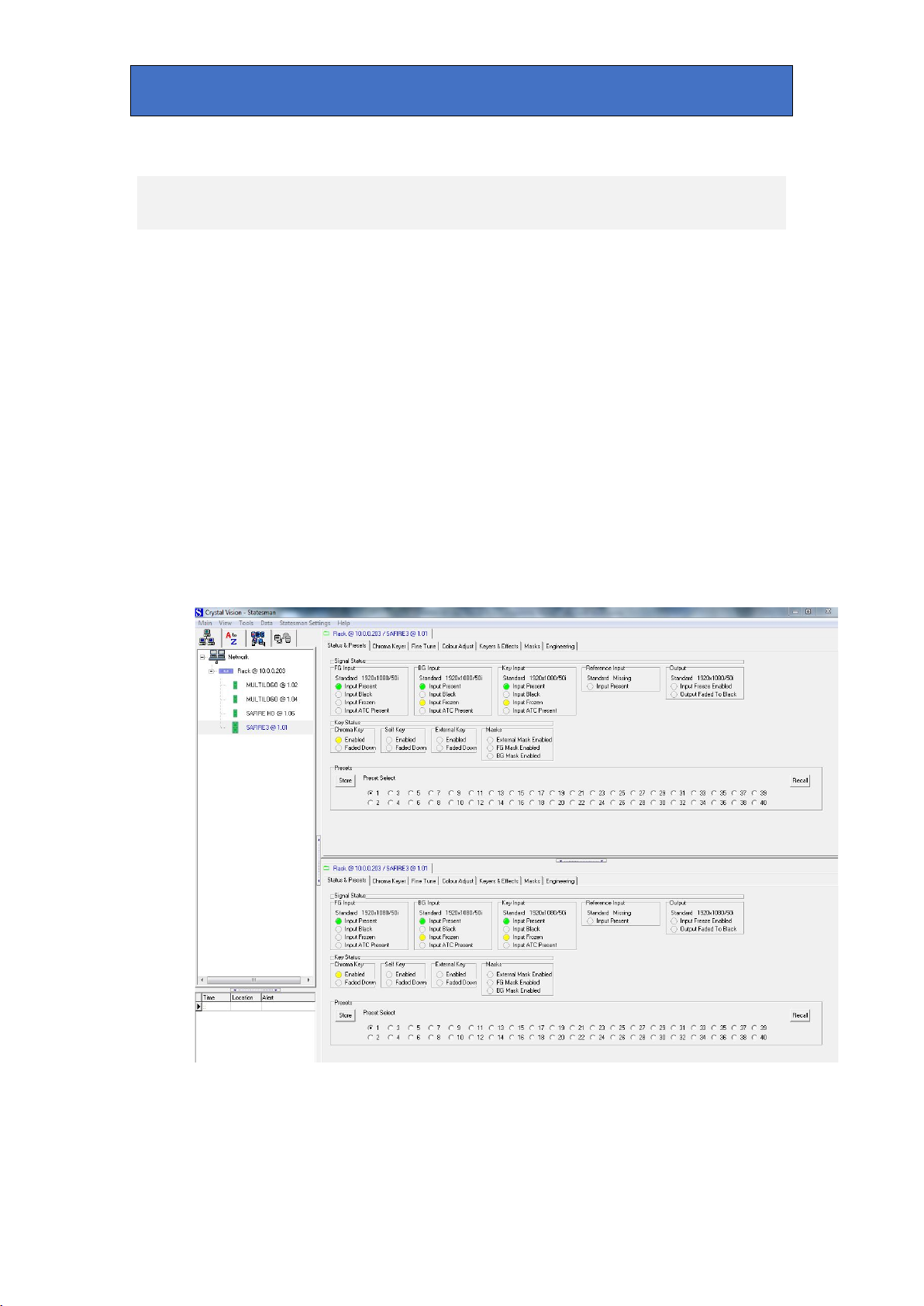
Crystal Vision Appendix 1
13 Appendix 1
Statesman Control
Statesman software control of Safire 3 is no longer supported. The following is
included for users of Statesman up to v 4.51.
The Crystal Vision Statesman PC control software is designed to control a range of
Crystal Vision modules via Ethernet control from a PC. Statesman provides a user
friendly means of configuring and operating Crystal Vision modules with the benefit of
“see-at-a-glance” status monitoring.
The main Statesman application communicates with each module in a frame through
a Statesman-capable front panel CPU or full active control panel. Either of these must
be fitted to the frame to allow Statesman control.
Statesman operation
The initial view will show an Explorer style view of the connected frames and
modules. Double clicking on a module will enable the display of the main application
menus.
The two large control panes shown in the upper and lower halves of the window may
display different menus for the same card, or controls for different cards. Click on the
horizontal button-bar between the two panes to close the lower pane or drag the
button to vary the size of the panes.
Safire 3 User Manual R1.3 75 24 March 2017
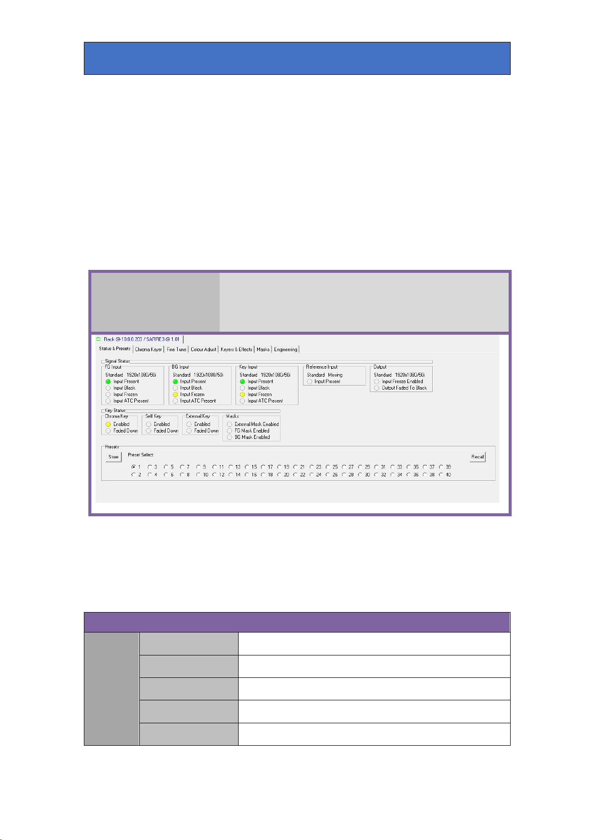
Crystal Vision Appendix 1
video frozen. If a LED turns red this is a fault condition. A greyed LED will
Signal Status
Statesman GUI controls are located in a number of tabs each containing panels which
mostly contain the controls. Some controls are LEDs that are used to show status,
others are check boxes, buttons or sliders which change various Safire 3 settings.
(Note: Slider controls, once highlighted, can be moved by the keyboard up and down
arrow keys to give finer control than possible with a mouse.)
The description of the tabs are in the order shown in the GUI i.e.
STATUS & PRESETS, CHROMA KEYER, FINE TUNE, COLOUR ADJUST, KEYERS
& EFFECTS, MASKS, ENGINEERING.
Each tab is shown with a screen grab and description of each control’s function:
The board status is shown using a mixture of simulated LEDs and text
Status &
information. As a general rule a green LED shows a good condition such
as input present. An amber LED will give a warning as with video black or
Presets
indicate an absence such as non-alarm or non-warning status.
FG/BG/Key
Input
Standard Displays input video standard e.g. 1920x1080/50i.
Input Present On when video input present.
Input Black On when input video is black level.
Input Frozen On when input video is frozen.
Input ATC Present On when ancillary timecode is present in input video.
Safire 3 User Manual R1.3 76 24 March 2017
Crystal Vision Appendix 1
Key Status
>Chroma Key Control.
On when Self Key is enabled. See Keyers & Effects tab->Self Key
Control.
tab ->Fade Keys.
External Key Control.
Effects tab->Fade Keys.
>External Mask Control.
Presets
Reference
Input
Output
Chroma
Key
Self Key
External
Key
Standard Displays ref video standard e.g. 1080/50i.
Input Present On when reference video present.
Standard Displays output video standard e.g. 1920x1080/50i.
Input Freeze Enabled On if input video freeze selected.
Output Faded to Black On if main output faded to black.
Enabled
Faded Down On when key is faded down. See Keyers & Effects tab->Fade Keys.
Enabled
Faded Down
Enabled
Faded Down
External Mask Enabled
On when chroma key mode is enabled. See Chroma Key tab-
On when self key is enabled and faded down. See Keyers & Effects
On when External Key is enabled. See Keyers & Effects tab->
On when external key is enabled and faded down. See Keyers &
On when External Mask is enabled. See Keyers & Effects tab-
Masks
FG Mask Enabled On when FG Mask is enabled. See Masks tab->FG Mask Control.
BG Mask Enabled On when BG Mask is enabled. See Masks tab->BG Mask Control.
Store Store Safire 3 settings as one of 40 presets.
Preset Select Select preset to store or recall.
Recall Recall one of 40 previously stored settings.
Safire 3 User Manual R1.3 77 24 March 2017
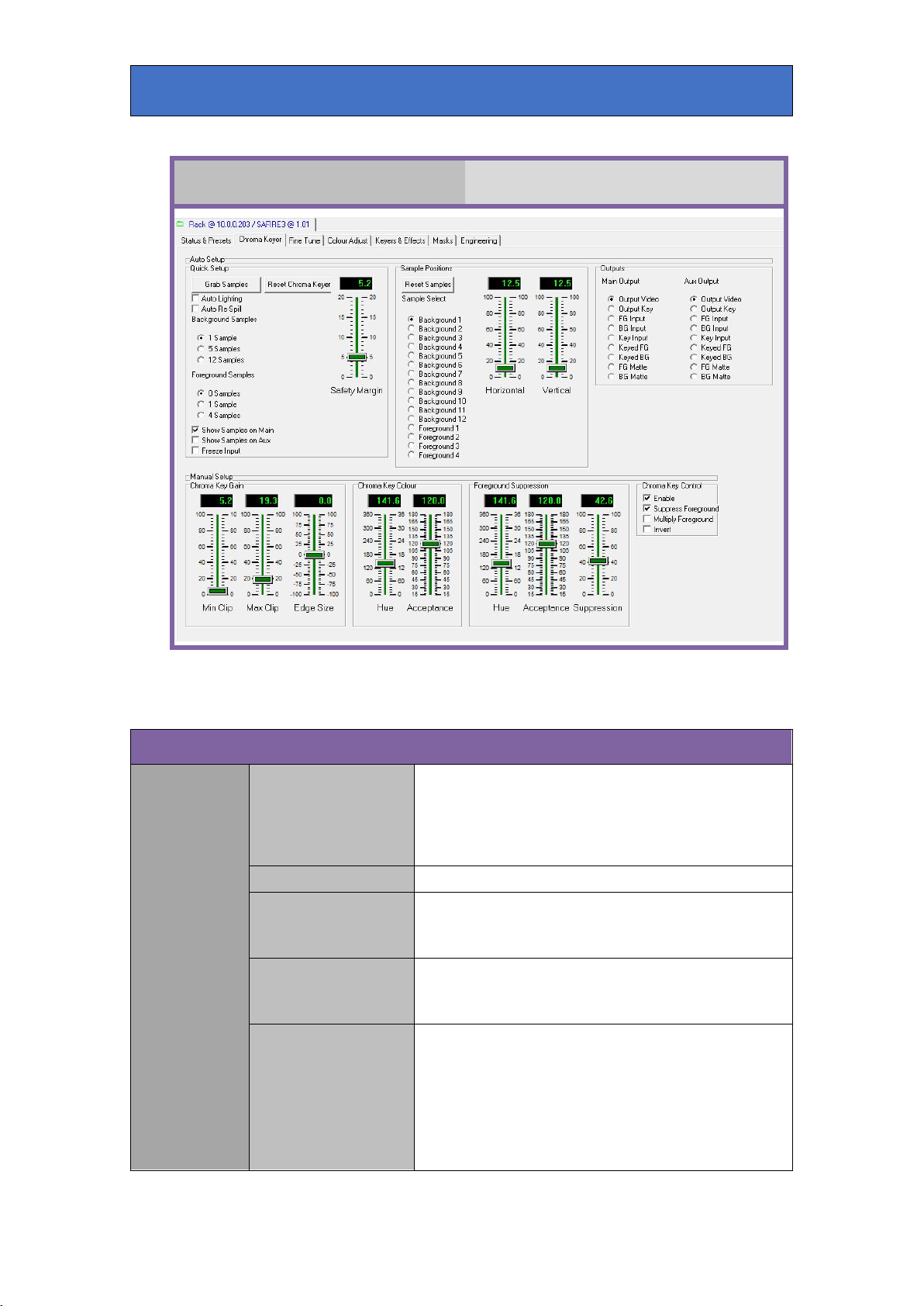
Crystal Vision Appendix 1
Chroma Key
Auto Setup
Auto and manual setup of Chroma Keyer.
Quick Setup
Set up Safire 3 using FG samples taken from the backdrop
Grab Samples
Reset Chroma Keyer Return Safire 3 to its calibrated settings.
Auto Lighting
Auto Re-Spill
Background Samples
and foreground areas. The following parameters are
automatically adjusted: Max Clip; Chroma Key Colour - Hue;
Foreground Suppression - Hue, Acceptance & Suppression;
Chroma Key Tune - Key Saturation.
Select to automatically compensate for lighting fade-off
towards the edges when grab samples is selected. See Fine
Tune tab->Lighting Compensation.
Select to automatically compensate for any backdrop colour
spill on FG objects when grab samples is selected. See
Colour Adjust tab->FG Re-Spill.
Select 1, 5 or 12 samples from the backdrop area of the FG
picture to use for auto setup. Samples are (optionally) visible
on the main and/or aux outputs and can be re-positioned.
These samples are used to automatically select optimum
chroma key values to allow for variations in chroma key
backdrop hue and saturation. Usually the more samples
chosen, the more accurate the result.
Safire 3 User Manual R1.3 78 24 March 2017

Crystal Vision Appendix 1
rectangles on the Main output.
Select which signal is routed to the Main output:
Auto Setup (contd.)
Select 0,1 or 4 samples from the foreground area of the FG
picture to use for auto setup. These samples are (optionally)
visible on the main and/or aux outputs and can be repositioned as necessary. These samples are used to amend
the settings of the chroma keyer to isolate regions in
foreground areas that may cause unwanted keying by
forcing the key signal to zero at these points.
Select this to display the sample positions as small
Select this to display the sample positions as small
rectangles on the Aux output.
Select this to freeze the FG input signal. This is useful to
enable accurate positioning of the backdrop and foreground
samples when the subject is moving.
Adjust this control to minimise the effect of noisy samples
on the auto setup. As auto setup parameters are calculated
from a single frame, a noisy picture may give false samples.
This control adjusts the levels of the samples to
compensate.
Quick Setup
(contd.)
Foreground Samples
Show samples on Main
Show samples on Au x
Freeze Input
Safety Margin
Sample
Positions
Horizontal/Vertical
Outputs
Reset Samples Return sample positions to their default locations.
Sample Select
Main Output
Aux Output Select which signal is routed to the Aux output.
Select which sample to re-position - the selected sample will
slowly flash on the main and/or aux output.
Adjust the sample's position horizontally and vertically to the
desired location.
Output video: the composite chroma keyed result.
Output key: the key signal, as a monochrome image,
produced by the combination of the chroma keyer, other
keys and masks.
FG input: the Foreground video input.
BG input: the Background video input.
Key input: the external key input signal.
Keyed FG: the suppressed Foreground image after chroma
keying. This signal is useful for fine adjustment of the
various controls to optimise the removal of the key colour
from the subject.
Keyed BG: the Background signal after keying. This signal is
useful in fine adjusting the key gain and other controls.
FG Matte: display the matte colour set by the keyers and
effects/FG source and matte controls.
BG Matte: display the matte colour set by the keyers and
effects/BG source and matte controls.
Safire 3 User Manual R1.3 79 24 March 2017

Crystal Vision Appendix 1
Manual Setup
for this control is 0.
through to the foreground.
Adjust the offset of the key signal that will cut a hole in the
new Background video signal. Increasing the min clip value
will force lower key levels to zero. This is mainly used when
small amounts of key level remain in foreground object areas
causing breakthrough of the new background. Any increase
Min Clip
in min clip value will have to be compensated for by
reducing the max clip value to restore the key in other areas.
Note that shadows and scuffs appear as high to mid level
key values and that increasing the min clip setting and
reducing the max clip setting will tend to accentuate these.
The effect of this control is best observed by monitoring the
Output Key. The default level for this control is 0.
Chroma Key
Gain
Chroma Key
Colour
Max Clip
Edge Size
Hue
Acceptance
Adjust the gain of the key signal that will cut a hole in the
new Background video signal. Reducing the max clip level
value will force variations in key level to full key value by
amplifying and clipping. Use this control to compensate for
uneven chroma key backdrop illumination. Adjusting this
control is a compromise between removing key variations
and retaining key edge detail. The effect of this control is
best observed by monitoring the Output Key. The default
level for this control is 50.
Adjust the shape of the key. When the key signal is amplified
it loses its original shape and this can cause a black line
around foreground objects when the new background is
added. Adjusting the key edge shape can help to
compensate for this. Note that changing the key shape can
also be used in conjunction with the min clip control to
subtly change the appearance of shadows. The default level
Set the colour that will be used by the new Background key
circuitry. Monitor the output key and with the acceptance
control set to 90 degrees and the min and max clip controls
set to default values adjust the control to give the best
overall key. Note: it may help to invert the key output in the
Engineering menu so that full key level is peak white and no
key is black. Note also: this control rarely needs adjusting
after auto setup.
Adjust this control to change the range of colours about the
hue colour (acceptance angle) used by the new Background
key circuitry. Monitor the output key and with the min and
max clip controls set to default values, adjust this control to
give the best overall key. Note: It may help to invert the key
output in the Engineering menu so that full key level is peak
white and no key is black. Setting the acceptance value too
small may result in an uneven key in the chroma key
backdrop area. Too large a value may cause keying in
foreground areas resulting in the new background breaking
Safire 3 User Manual R1.3 80 24 March 2017
Crystal Vision Appendix 1
possibly causing a black halo around FG objects.
Manual Setup (contd.)
Set the colour that will be used by the Foreground
suppression circuitry. Monitor the Keyed FG signal and
adjust this control to suppress the chroma key backdrop
colour. Note that often there is a variation in backdrop colour
Hue
Acceptance
Foreground
Suppression
caused by lighting etc. so adjust this control to give the best
suppression in the most noticeable areas. This control is
best adjusted with the suppression control set mid-way and
the acceptance control set to 90 degrees to see the effect
most clearly. Note also: this control rarely needs adjusting
after auto setup.
Adjust this control to change the range of colours about the
hue colour (acceptance window) suppressed by the
Foreground suppression circuitry. Monitor the Keyed FG
signal and adjust this control to entirely suppress the
chroma key backdrop colour. If the acceptance angle is set
too small, then due to variations in backdrop colour, a colour
tint may remain in places. If the angle is set too large then
unwanted suppression may occur on foreground objects.
Adjust the hue control as well to get the best compromise if
there are large variations in backdrop colour. This control is
best adjusted with the suppression control set mid-wa y to
see the effect most clearly.
Adjust this control to set the suppressed backdrop area to
black. Monitor the keyed FG signal and set the control to the
minimum level necessary to give a solid black in the chroma
key backdrop area. This control is best adjusted after the
hue and acceptance controls have been set and – because
because of their interactive nature – the min and max clip
Suppression
controls set to their default values. Note that when the
suppressed FG signal and keyed Background signal are
added together to form a final composite, any luminance in
the FG backdrop area will be added to the new background.
This can sometimes be compensated for with BG lift
reduction in the BG Match sub menu of the Colour Adjust
tab, but every attempt should be made to achieve as close to
black as possible. Over-suppressing will distort edges
Safire 3 User Manual R1.3 81 24 March 2017

Crystal Vision Appendix 1
foreground colours.
Manual Setup (contd.)
Chroma Key
Control
Suppress Foreground
Multiply Foreground
Enable
Invert
Select this to enable chroma key operation on the
foreground.
Select this to enable FG suppression. This is usually always
selected if 'Multiply Foreground' is NOT selected. If 'Multiply
Foreground' IS selected then deselecting this option can
sometimes give better results if FG suppression has altered
Select this to multiply the Foreground by the inverse of the
new Background key. If de-selected, the FG is added to the
keyed background. With good lighting and a high quality
chroma key backdrop it is usually better to not select
'Multiply Foreground' as FG Suppression and non-multiply
mode give better results particularly with fine detail such as
hair. However sometimes it is not possible to fully suppress
all backdrop detail from the FG picture and that can show in
the final composite. In this case multiply mode will cut out
the backdrop entirely, but at the expense of fine detail. The
different modes should be tried to see what gives the best
result.
In Multiply Foreground mode this control will invert the
generated key – thereby swapping the FG and BG pictures in
the final composite.
Safire 3 User Manual R1.3 82 24 March 2017

Crystal Vision Appendix 1
Chroma Key Adjust
setup.
Fine Tune
Adjust chroma key settings for optimum performance.
Chroma Key
Removal
Lighting
Compensation
Black/Greys/White
Enable
Aspect Ratio
Left/Right/Top/Radial
Use these controls to attenuate the new background key in
foreground areas of black, grey or white. This is useful
where colour spill from the chroma key backdrop onto
foreground objects are causing unwanted keying of the
background.
Select this to activate lighting compensation. This feature is
enabled if 'auto lighting' is selected in quick setup.
Select aspect ratio of radial lighting compensation
parameter. Note that quick setup assumes 4x3 which is
primarily for Standard Definition.
These controls help compensate for uneven backdrop
lighting. The lighting distribution of a spotlight is a bright
centre that fades away to the edges in a circular pattern. The
Background key produced when a spotlight is used to
illuminate a chroma key backdrop will reflect that lighting
distribution. Increasing key gain (max clip) will help
compensate for that but at the expense of fine detail. By
monitoring the output key and adjusting the lighting
compensation controls it is possible to minimise the effects
of lighting edge fade. With max clip set to 100, adjust the
radial and position controls to provide as even a key
distribution in the backdrop area as possible. These controls
are automatically set if 'auto lighting' is selected in quick
Safire 3 User Manual R1.3 83 24 March 2017
Crystal Vision Appendix 1
Chroma Key Refine
prominent and decreasing less prominent.
maintaining fine edge detail.
This control moves the acceptance window of the FG
suppressor circuitry about the selected backdrop hue. This
Foreground Balance
control is useful when the FG objects contain colours close
to the backdrop colour and so can help minimise
desaturation of some FG colours while maintaining good
backdrop colour suppression.
Chroma Key
Tune
Chroma Key
Filters
Foreground Tints
Background Saturation
Shadow Density
Ring Suppression
Noise Reduction
Edge Softening
This control allows areas of the foreground that contain low
saturation levels of the backing colour to be passed without
being suppressed.
This control helps compensate for a poorly saturated camera
output in FG backdrop areas. Ideally, a well lit backdrop
would produce a 100% saturated colour output from the
camera; but this is rarely the case. While monitoring the
output key and with max clip set to 100, adjust this control to
provide an even and low noise key in the backdrop area. The
max clip control can then be adjusted to amplify the key to
full level. This control is automatically set by quick setup.
This control changes the appearance of shadows. Increasing
the value of this control will make shadows appear more
This control helps minimise ringing introduced by the
camera.
This control adds a variable amount of filtering to the
Background key signal to help minimise noise while
This control adds a variable amount of filtering to the
Background key signal to smooth jagged edges caused by
high levels of key gain and to minimise noise.
Outputs Main/Aux Outputs
Select which signal is routed to the main and aux outputs.
See Chroma Keyer tab for details.
Safire 3 User Manual R1.3 84 24 March 2017

Crystal Vision Appendix 1
FG & BG Colour Match
Adjust FG and BG video levels to match each other to
Colour Adjust
give best composite image. Colour correct FG signal.
Colour adjust in areas tinted by backdrop colour.
FG Match FG Lift/Gain/Chroma
BG Match BG Lift/Gain/Chroma
These controls modify the FG video signal so it matches the
keyed Background in the final composite. Monitor the output
video and use the lift, gain and chroma controls to achieve
the best results.
These controls modify the BG video signal so it matches the
keyed Background in the final composite. Monitor the output
video and use the lift, gain and chroma controls to achieve
the best result. These controls are left untouched by quick
setup. BG lift control can help reduce any luminance added
to the composite by the suppressed FG if some luminance
remains in the FG backdrop areas.
FG & BG Colour Match (contd.)
Safire 3 User Manual R1.3 85 24 March 2017
Crystal Vision Appendix 1
FG Colour Correct
Enable
FG Re-Spill
Red/Green/Blue
FG Gain Red/Green/Blue Gain
FG Lift Red/Green/Blue Lift
Select this to enable FG re-spill in areas of the foreground
that were tinted by the backing colour. This control is
selected if 'auto re-spill' is selected in quick setup.
These controls add a colour tint to the backdrop spill areas
of the suppressed FG picture to counteract any noticeable
colourisation. When an object is placed in front of a green
backdrop, say, it will experience a green spill around its
edges and reflecting surfaces, but if a blue background (i.e.
sky) was chroma keyed behind, the green spill would look
unnatural. Adding a blue FG re-spill in this case would
produce a more realistic composite. These controls are
automatically set if 'auto re-spill' is selected in quick setup.
These controls adjust the individual red, green and blue
gains of the suppressed FG signal between 80% - 120%.
These controls give positive and negative lift to the
individual red, green and blue channels of the suppressed
FG signal.
Safire 3 User Manual R1.3 86 24 March 2017

Crystal Vision Appendix 1
Keyers
FG to adjust this control.
Enable and adjust self key. Set up external key input as key
and mask. Fade keys in and out, automatically and manually.
Keyers & Effects
Select sources for FG and BG. Adjust FG and BG matte
colours. Fade output to and from black.
Self Key Control
Select to use the luminance of the FG signal as a key. The
Enable
Multiply
Invert Select to invert the clipped key.
Min Clip
Max Clip
BG is keyed and filled with the FG source. Use this control to
key a caption derived from the FG video into the Background
video and fill with a matte, black or video. Usually chroma
key mode would be disabled if self key mode is enabled.
Select to key the FG signal before adding to the keyed BG
signal. Select if the FG signal is not black outside of the
caption fill area.
Use this control to clip all key signals below the threshold
set by the control – i.e. if the control is set to 20 then all key
levels up to 20% of max will be removed. Monitor the keyed
Use this control to amplify and clip all key signals above the
threshold set by the control – i.e. if the control is set to 80,
then all key levels above 80% of max will be clipped and
amplified to full scale. Monitor the keyed FG to adjust this
control.
Safire 3 User Manual R1.3 87 24 March 2017

Crystal Vision Appendix 1
Keyers (contd.)
Select to enable the External Key signal as a key. The BG
picture is keyed and filled with the FG source. Use this
control to key a caption into the Background video and fill
Enable
with matte, black or video. This key augments the chroma
key and self key in its active areas. In chroma key mode this
key will force the FG video to mask chroma keying in
unwanted regions. The external key combines with the self
key to extend the size of the key.
External Key
Control
External Mask
Control
Multiply
Invert Select to invert the clipped key.
Min Clip
Max Clip
Enable
Multiply
Invert Select to invert the clipped mask.
Select to key the FG signal before adding to the keyed BG
signal. Select if the FG signal is not black outside of the
caption fill area.
Use this control to clip all key signals below the threshold
set by the control – i.e. if the control is set to 20 then all key
levels up to 20% of max will be removed.
Use this control to amplify and clip all key signals above the
threshold set by the control – i.e. if the control is set to 80,
then all key levels above 80% of max will be clipped and
amplified to full scale.
Select to enable the external key signal as a mask. The mask
signal disables the self key and chroma key in its active
areas. If the chroma key is enabled the mask will force the
final composite to Background and this can be used to
compensate for missing backdrop areas or to promote an
area of Background to the front of the composite.
Multiply mode is the normal way of using the external mask;
the suppressed FG signal is keyed with the mask prior to
adding to the BG. In non-multiply mode the FG signal is not
keyed and added to the BG signal.
Min Clip
Max Clip
Use this control to clip all key signals below the threshold
set by the control – i.e. if the control is set to 20 then all key
levels up to 20% of max will be removed.
Use this control to amplify and clip all key signals above the
threshold set by the control – i.e. if the control is set to 80,
then all key levels above 80% of max will be clipped and
amplified to full scale.
Safire 3 User Manual R1.3 88 24 March 2017
Crystal Vision Appendix 1
Effects
take.
Keyers (contd.)
Use this control to automatically fade enabled keys up and
Auto Trans
down at the rate set by the Fade Time control. In chroma key
mode the FG image will be faded up and down but masks are
unaffected. External and self key will fade up and down.
Fade Keys
FG Source and
Matte
BG Source and
Matte
Fades Up/Down
Fade Time
Fade Use this control to manually fade keys up and down.
FG Source
Red/Green/Blue Set the FG colour matte using these controls.
BG Source
Red/Green/Blue Set the BG colour matte using these controls.
These indicate which direction the autotrans operation will
take.
Use this control to set an autotrans fade time of 0-100
seconds.
Use these controls to select the FG signal. Select either FG
video, black or the colour matte – usually FG video for
chroma keying.
Use these controls to select the BG signal. Select either BG
video, black or the colour matte – usually BG video for
chroma keying.
Fade to Black
Autotrans
Fades Up/Down These indicate which direction the autotrans operation will
Fade Time
Fade Use this control to manually fade to/from black.
Use this control to start an automatic fade to black transition
of the video output at a rate set by the Fade Time control.
Use this control to set an autotrans fade time of 0-100
seconds.
Safire 3 User Manual R1.3 89 24 March 2017

Crystal Vision Appendix 1
FG Mask
The FG and BG masks are used to override the chroma key to
either force the BG image in areas of poor backdrop quality or to
Masks
disable in unwanted areas. Note that the masks also have an effect
on the self key and external key signals.
FG Mask Control
FG Mask
Window
FG Mask
Softness
Select this control to enable the FG mask. This user-
Enable
Invert Select this control to invert the mask.
Left/Right/Top/Bottom Use these controls to position the mask rectangle.
Left/Right/Top/Bottom
positionable mask will override the chroma key in its active
area to force the BG signal. Use this mask if the chroma key
backdrop is too small or damaged, or badly lit at the edges.
Use these controls to soften the four edges of the mask to
make the mask less noticeable.
Safire 3 User Manual R1.3 90 24 March 2017
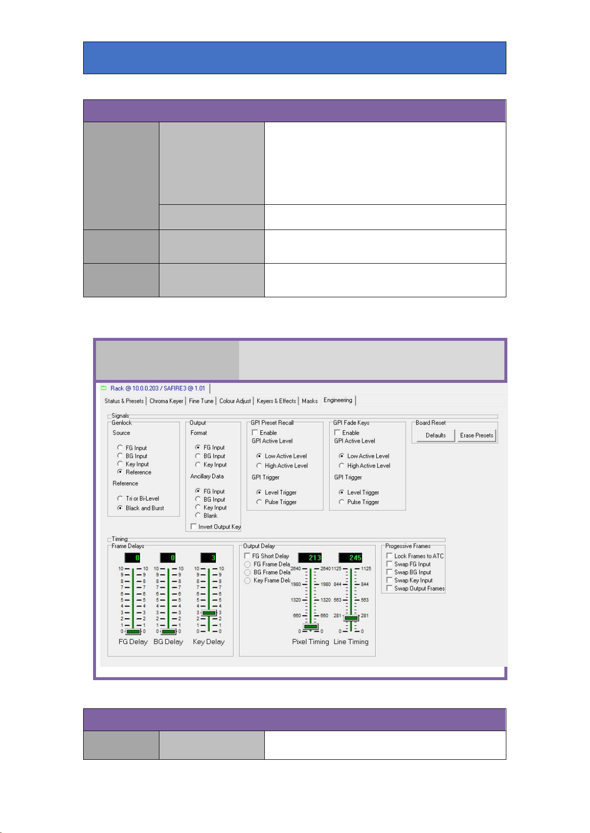
Crystal Vision Appendix 1
BG Mask
Signals
Select this control to enable the BG mask. This userpositionable mask will override the chroma key in its active
Enable
BG Mask Control
Invert Select this control to invert the mask.
area to force FG video. Use this mask to disable the chroma
key in FG non-backdrop areas containing the key colour, or
reflective objects. Note that the BG mask does not override
FG suppression, only the BG key.
BG Mask
Window
BG Mask
Softness
Left/Right/Top/Bottom Use these controls to position the mask rectangle.
Left/Right/Top/Bottom
Engineering
Use these controls to soften the four edges of the mask to
make the mask less noticeable.
Control engineering functions such as genlock, timing and board
reset.
Genlock Source Select which source Safire 3 will use as its reference.
Safire 3 User Manual R1.3 91 24 March 2017
Crystal Vision Appendix 1
Select whether the external analogue reference input is Tri-
unless 'Reference' is selected as the genlock source.
output.
data.
Timing
selected, add 5 line delay to the above values.
Output
GPI Preset
Recall
GPI Fade Keys
Reference
Format Select which input video format should be used for the video
Ancillary Data Select which video input is the source of output ancillary
Invert Output Key
Enable
GPI Active Level
GPI Trigger
Enable Select to enable fading of keys by GPI.
GPI Active Level Select low or high level as the active level for the GPI.
GPI Trigger
Level or Black & Burst. No reference needs to be applied
Select this to invert the output key. Use this to match the key
polarity with other equipment or for monitoring purposes to
make the key more visible.
Select to enable recall of presets by GPI. Presets 1-32 can be
selected from the binary coding of the external GPI inputs.
Select low or high level as the active level for the GPI
signals.
Select whether GPI recall should be triggered by a change in
level or a pulse.
Select whether GPI triggering should be triggered by a
permanent change in level or a transition.
Defaults
Board Reset
Erase Presets
Frame Delays FG/BG/Key Delay
FG Short Delay
FG/BG/Key Frame Delay
Output Delay
Pixel Timing
Line Timing
Select to restore Safire 3 to default conditions without
erasing stored presets.
Select to restore Safire 3 to default conditions AND erase
stored presets.
These controls delay the selected video by up to ten frames
at the Safire 3's inputs.
Select this to disable the Noise Reduction and Edge
Softening filters to minimise propagation delay. Short Delay
for SD = 85uS, HD = 18uS, 3G = 10uS. Without Short Delay
Indicates whether the output signal is more than one whole
frame delayed with respect to each input.
Delay output video horizontally by 0 to 2640 pixels with
respect to reference. (See note below)
Delay output video vertically by 0 to 1125 lines with respect
to reference. See note above for max delay. Note: the total
Pixel + Line delay can not exceed one frame for any output
standard. E.g. 720 lines is the maximum delay for 720p
standard.
Safire 3 User Manual R1.3 92 24 March 2017
Timing (contd.)

Crystal Vision Appendix 1
Lock Frames to ATC Lock the HD progressive video output to Ancillary Timecode.
Progressive
Frames
Swap FG/BG/Key Input Swap field sequence of the selected progressive video input.
Swap Output Frames Swap field sequence of the progressive video output.
Safire 3 User Manual R1.3 93 24 March 2017
 Loading...