

Page 1
Zero
Latency
PRO 200
User Manual
Model:7051+3051
Version:1.0
2018. 03.26
Page 2
Page 3
Contents
About the User Manual
- Please re ad this manua l careful ly before y ou use this product and retain it properly
for future reference.
- If there is a ny question o r difficult y about the ope ration of p roduct, p lease feel free
to contac t us or the deale r.
About the User Manual
Brief introduction
Features
Packing list
Specification
Interface Information
Quick Start Guide
LED Digits Display description
Application Recommendations
Trouble shooting
02
02
02
03
04
05
09
14
16
19
- CVW reser ves the authority to modify the inst ruction manuals.
Brief Introduction
As the widely u se of live broad casting , man y problems about wiring appear, su ch as
the high cost and short life time of the cable. F ur th er, some o ther factor s affect the
user experi ence of live broadcast, such as the insufficient cable protect ion and the
tread bycrowde d people, whi ch will lead to t he poor cable t ransmissi on capabi lity or
even to acc ident. PRO200 prov ides you more convenie nt and safer so lution for li ve
broad casting. Wi th the advantage of long distance transmission, plug-and-play usag e,
it can satisf y your various indoor and out door shooting requirements. W ith additio n of
its free ca ble wiring ne eded,it wil l bring much sa fer and more profe ssional experience
to you!
Features
The produ ct with its tra nsmission d istance of up to 200 meters can meet th e demands
of film shooting, te levision broadca sting, live e vents, large conference, etc.
The produ ct delivers u ncompre ssed real-time 1080P/60Hz full HD video (4:2:2, 10bit).
Support HDMI, HD- SDI, 3G-SDI .
Full hard ware desi gn, plug & play ;
5.1G-5. 9G,suppor t manu al seting for channel sw itching and broadcast mod e.
Support SDI time co de transmis sion (time co de format: ATC_VITC, ATC_LTC).
Support SDI camer a recording trigge r function (Start/Stop Flag) transmission.
Comply with E DID 1.1 ,supp or t HD MI 1.3.
Support AES128 bi t encr yp tion.
Page 4
Packing List
Specification
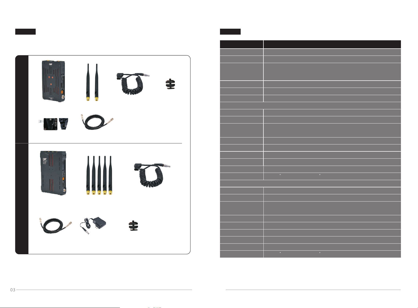
Please chec k the packa ge inside to assure it contains the par ts as below,
if any parts miss ed, please co ntact the dis tributor or us.
Trans mi tter
Tran smitter * 1
Mount * 1
-
V
*
Op
tion
l
a
Anten na * 2
SDI Cab le *1
Power Cable * 1
2- Pin L emo to D- Tap
Hot-sh oe
Sta nd * 1
Rece iv er
Power Cable * 1
Rec eiver * 1
SDI Cab le *1
Anten na * 5
DC Adap ter * 1
12V 2A Le mo 2 pin
*Opti onal
* Some of the accessories are optional with extr a cost, if you need to purchase,
please cont act the distr ibutor or u s.
* If some chang es on the appea rance,log o and accesso ries, subje ct to the actual
received product.
2- Pin L emo to BTap
Hot-sh oe
Sta nd * 1
Item
Frequency
Bandw idth
Video F ormat s
Audio F ormat s
Time Co de
Transmission distance
Image transmission:5.1~5.9GHz
40MHz
1080P 2 3.98/ 24/25/30 /50/6 0
1080i 5 0/59. 94/60
576P 57 6i 480p 480i
PCM
ATC_VITC ATC_LTC
Up to 200m
Specifica tion
1080p sf 23.9 8/24/25
720P 50 /59.9 4/60
Transmitter
Anten na
Tran smiss ion Powe r
Inter face
Mecha nical I nterf ace
LED Dig its Dis play
Working Voltage
Power Consumption
Size(mm)
Tempera ture
Exter nal antenn a * 2
17dBm
HDMI input,SDI input, Mini-USB,Lemo(0B/2pin) DC in,
Antenna RPSMA, Power switch
V-mou nt, 1/4 " fixing scr ew hole
Wor king ch anne nu mber
7V~36 V
<8W
117.5*72*27.5mm
-10~50 C(Working);-40~80 C( Storage)
Receiver
Anten na
Rec eiver S ensitivity
Inter face
Mecha nical I nterf ace
LED Dig its Dis play Displ ay the working chan nel
Working Voltage
Power Consumption
Size(mm)
Tempera ture
* As the product's continous improvmen t, the performa nce, design a nd specifications
are subje ct to minus change without prior notice.
Exter nal antenn a *5
-70dBm
HDMI ou tput, S DI output, M ini-U SB,Le mo(2pin) DC in,
Anten na RPSMA,Power sw itc h
V-mou nt, 1/4 " fixing screw hole
7V~36 V
<7W
144*95*27.5mm
-10~50 C(Working);-40~80 C( Storage)
04
Page 5
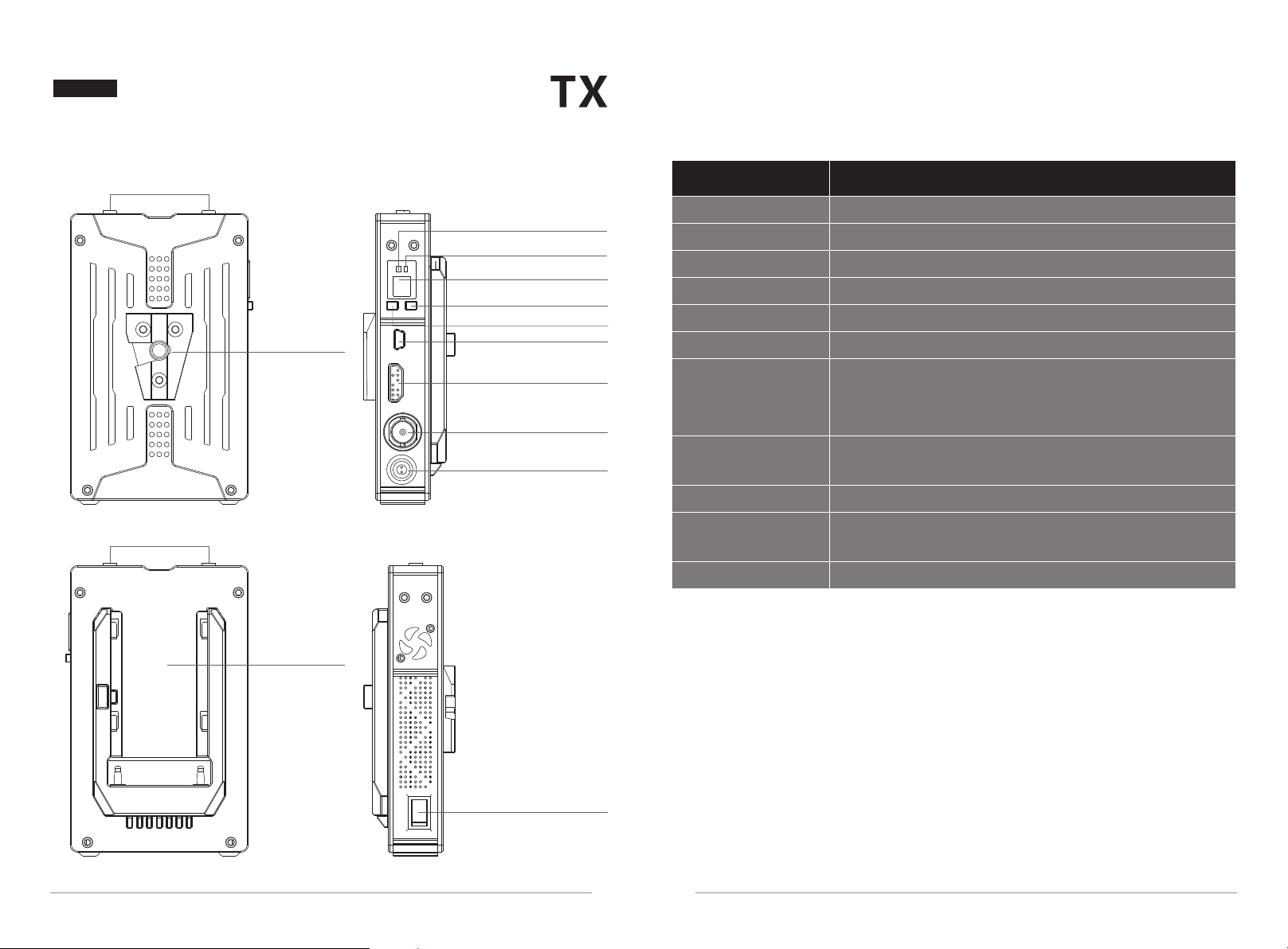
Interface Information
Transmitter Interface
Model:7051
5.8G Antenna
Interface
5.8G Antenna
Interface
V- MOU NT
Po we r in di c at or
Vi de o i nd ic at or
LE D Di g it s Di sp la y
OK B ut t on
CH B ut t on
Mi ni U S B
HD MI I N
SD I IN
DC -I N
Transmitter Interface Description
Item
LED Digits Display
OK Button
CH Button
Mini USB
HDMI IN
SDI IN
DC-IN
5.8G Antenna
Connector
V- MOUNT
Sony F-Type
Batter y Plate
Power Switch
Display the working channel 1~9, A(10), b(11)
Confirm the function selection
Switch the working channel
Be used for software upgrading
HDMI IN
SDI IN
Power input inter face (LEMO): support 7V to 36V
(Notice: please confirm the polarity before you
plugging in the power supply.)
Connect with RP-SMA antenna
Suppor t installation of V-mount devices
Be used for installing external Sony F-type batter y
Power ON/OFF
Specification
So ny F -Ty pe
Ba tt e ry P la te
Po we r Sw it c h
0605
Page 6
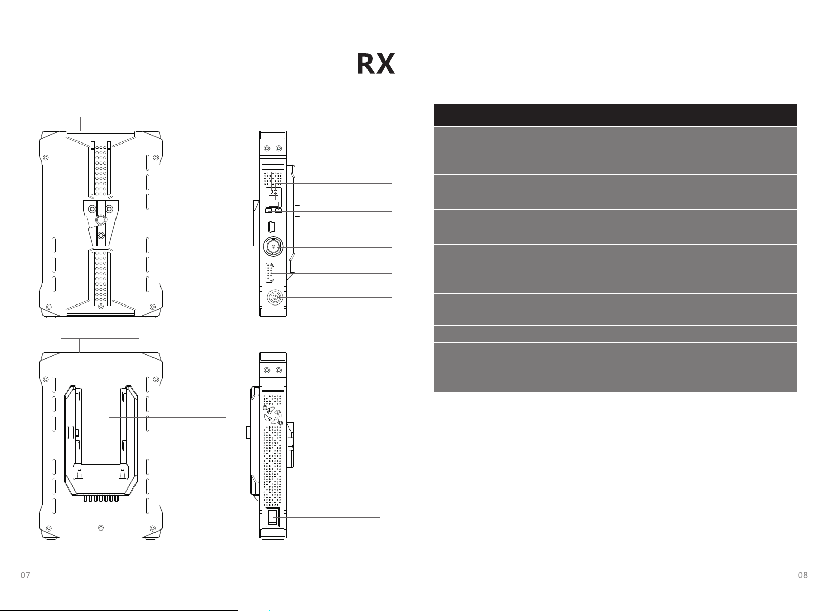
Receiver Interface
Model:3051
5.8G Antenna
Interface
Receiver Interface Description
Item
Specification
5.8G Antenna
Interface
V- MO UN T
So ny F -Ty pe
Ba tt e ry P la te
Po we r in di c at or
Vi de o i nd ic at or
LE D Di g it s Di sp la y
OK B ut to n
CH B ut to n
Mi ni U S B
SD I Ou t
HD MI O ut
DC -I N
LED Digits Display
OK Button (Dualfunction button)
CH Button
Mini USB
HDMI OUT
SDI OUT
DC-IN
5.8G Antenna
Connector
V- MOUNT
Sony F-Type
Batter y Plate
Power Switch
Display the working channel 1~9, A(10), b(11)
Confirm the function selection/Switching between
normal mode and enhanced anti-interference mode
Switch the working channel
Be used for software upgrading
HDMI OUT
SDI OUT
Power input inter face (LEMO): support 7V to 36V
(Notice: please confirm the polarity before you
plugging in the power supply.)
Connect with RP-SMA antenna
Suppor t installation of V-mount devices
Be used for installing external Sony F-type batter y
Power ON/OFF
Po we r Sw it c h
Page 7
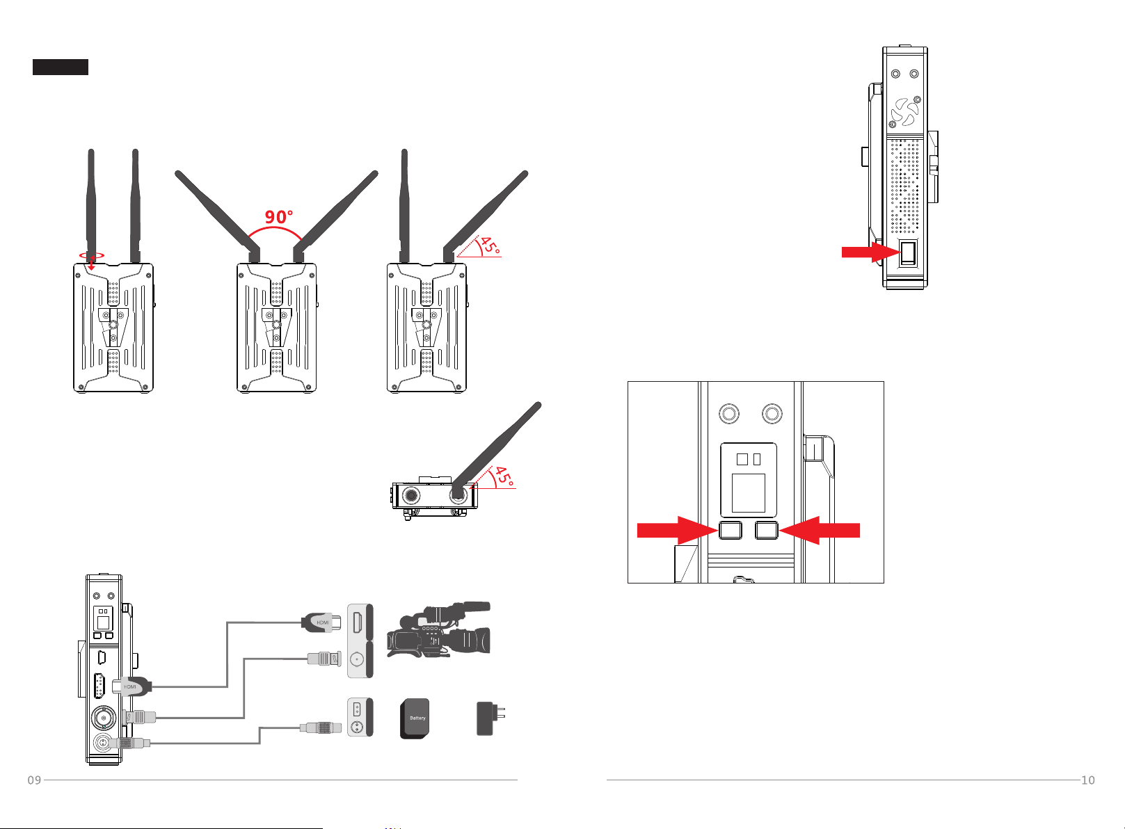
Product Installation
TX
Transmitter Installation Steps:
1. Fix the antennas and adjust their angles as shown in the figure below.
(For details, please refer to the transmission distance description.)
3. Turn on the power switch to start
power supplying.
Power Switch: ON turn on
OFF turn off
4.Press “CH” button to select the corresponding working channel of
receiver and then press “OK” button for confirmation.The LED digits
display will display one of the characters from 1 ~ 9, A and b when the video
signal of device is normal.(Tx and Rx use same default working channel)
Notice: pleas e rotate the golden
mental part of antenna to
fasten the antenna.
Antenn a Pat tern 1:
90° angle in the same plane
Ante nna Pattern 2:
Righ t side 45° angle
rotation tow ards bac kside
2. Connect Tx with the camera via corresponding
power cable and HD video cables as shown in the figure below.
H DM I
S DI D C
HDMI IN
SDI IN
DC IN
7V-36V
Camera
Li-bat ter y
12V power adapte r
5. The transmitter supports manually switching the SDI audio input mode by
long pressing “OK” button. (Notice: This function is only valid for SDI
audio input and won’ t affect the HDMI audio input.)The default value of
SDI audio input mode is 0 and the decimal point will be set to be non-bright
under this mode; long press “OK” key button for more than 3 seconds,
and then the LED digits display will display SDI audio input mode as 1 while
the decimal point will be bright.
Audio input mode 0: adopt internal SDI clock signal of TX
Audio input mode 1: adopt SDI clock signal of SDI input signal
Page 8
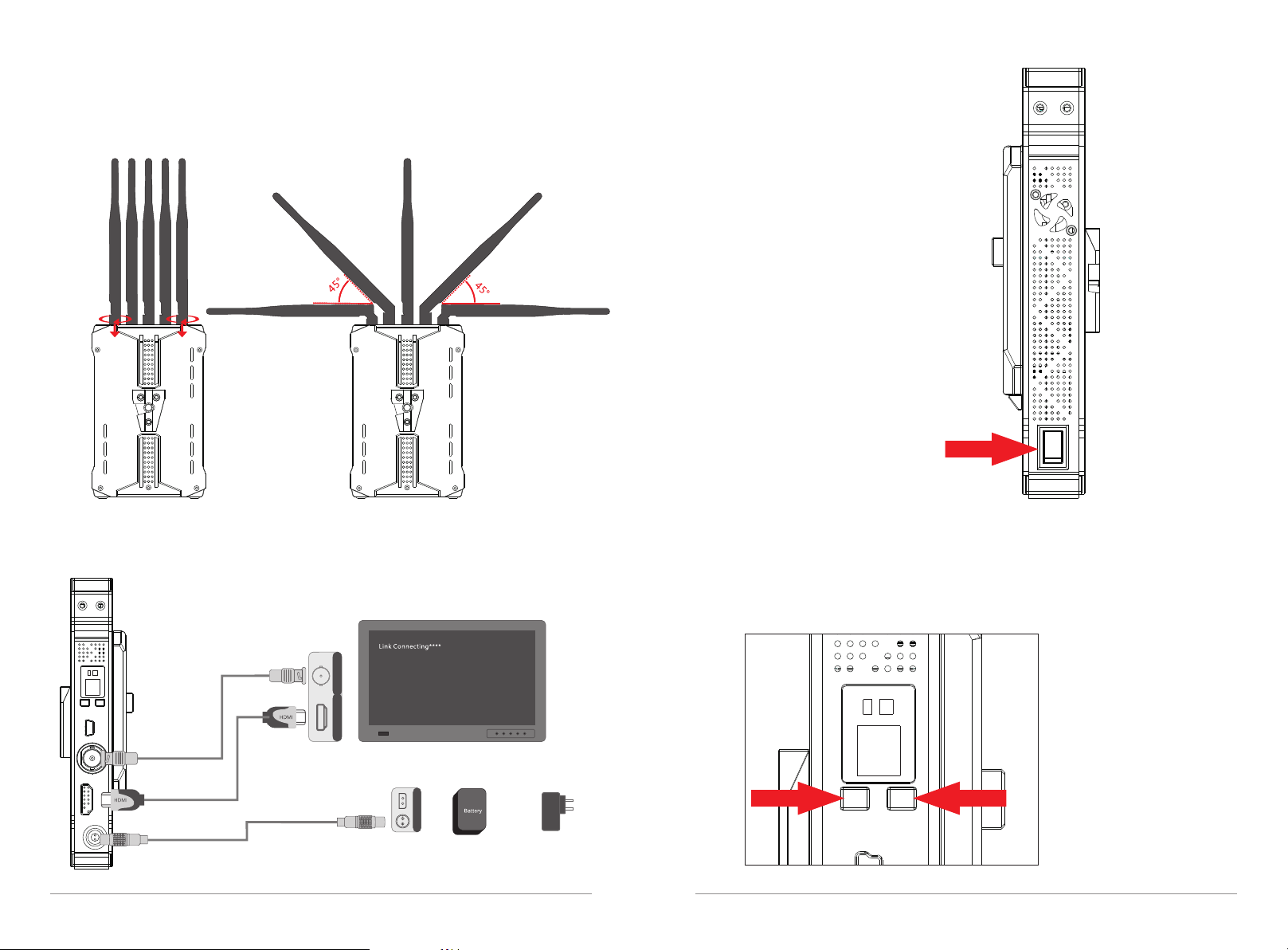
Receiver Installation Steps:
RX
1. Fix the antennas and adjust their angles as shown in the figure below.
Notice:
please rotate the
golden mental
part of antenna to
fasten the antenna.
3. Turn on the power switch to start
power supplying.
Power Switch: ON turn on
OFF turn off
2. Connect RX with the monitor via corresponding power cable and HD
video cables as shown in the figure below.
4. Press “CH” button to select the corresponding working channel of
receiver and then press “OK” button for confirmation.The LED digits
display will display one of the characters from 1 ~ 9, A and b when the
video signal of device is normal; the monitor will display the image from
camera simultaneously.
S DI
H DM I
SDI OUT
HDMI OUT
DC IN
11 12
7V-36V
SDI monitor
D C
Li-bat ter y
12V power adapte r
Page 9
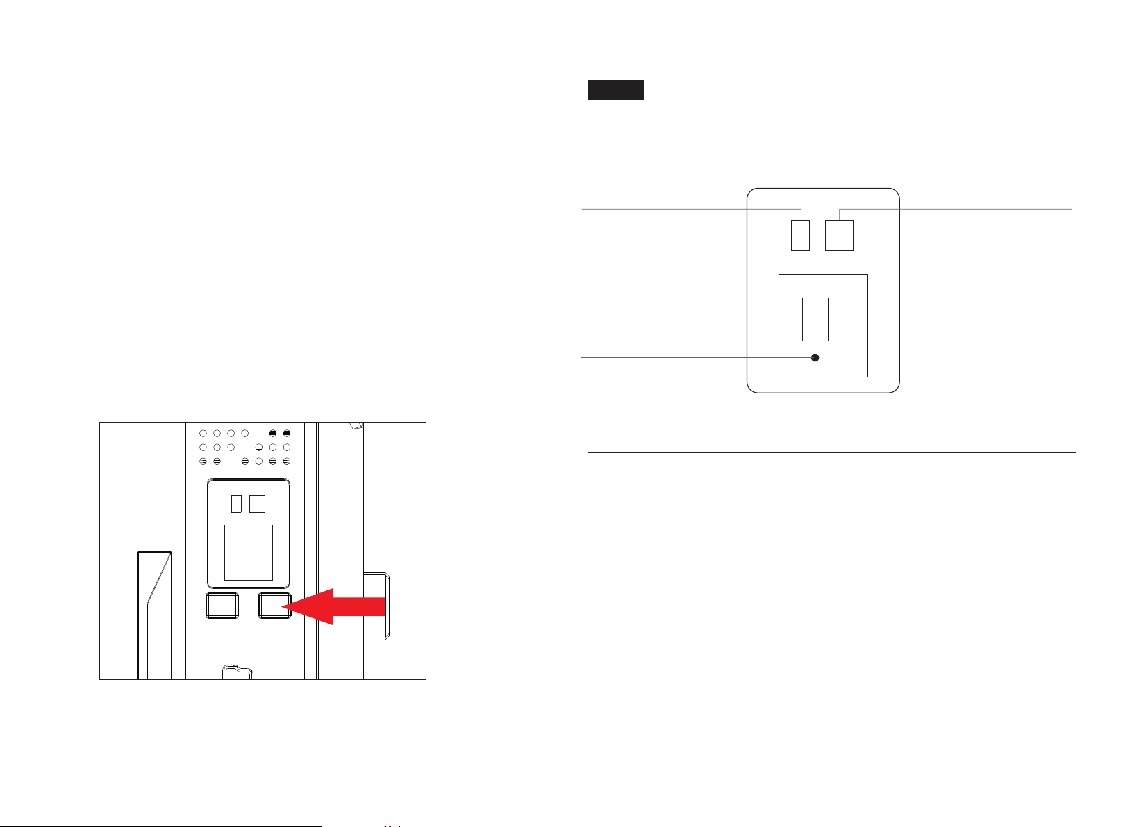
5. RX suppor ts switching between normal mode and enhanced anti interference mode according to transmission distance and
interference level
a) Switch from normal mode to enhanced anti-inter ference mode : long press
“OK” for longer than 3 seconds to enter enhanced anti-interference mode,
and decimal point of digital tube (indicator) starts to flash slowly.
b) Switch from enhanced anti-interference mode to normal mode: long press
“OK” for longer than 3 seconds to enter normal mode, and decimal point
of the digital tube(indicator) goes out
c) Normal mode is default setting, supporting memor y function,
so RX will enter last mode after reboot.
(Normal mode is recommended for long-distance transmission scenario;
enhanced anti-interference mode is recommended for short-distance
transmission and strong interference scenario)
LED Digits Display description
LED Digits Display Status
Power Indicator
TX : SDI Audio Input
Mode Indicator
RX : Normal/Enhanced
Anti-interference
Mode Indicator
Transmitter
Video Indicator
LED Digits Display
13
LED Digits Display: Channel 1 ~ 9, A(10), b(11)
Video Indicator: Red: HDMI input; Yellow: SDI input
Power Indicator: Illuminate in working mode
SDI Audio Input Mode Indicator:
Decimal point light is off : SDI Audio Input Mode 0
Decimal point light is on: SDI Audio Input Mode 1
14
Page 10
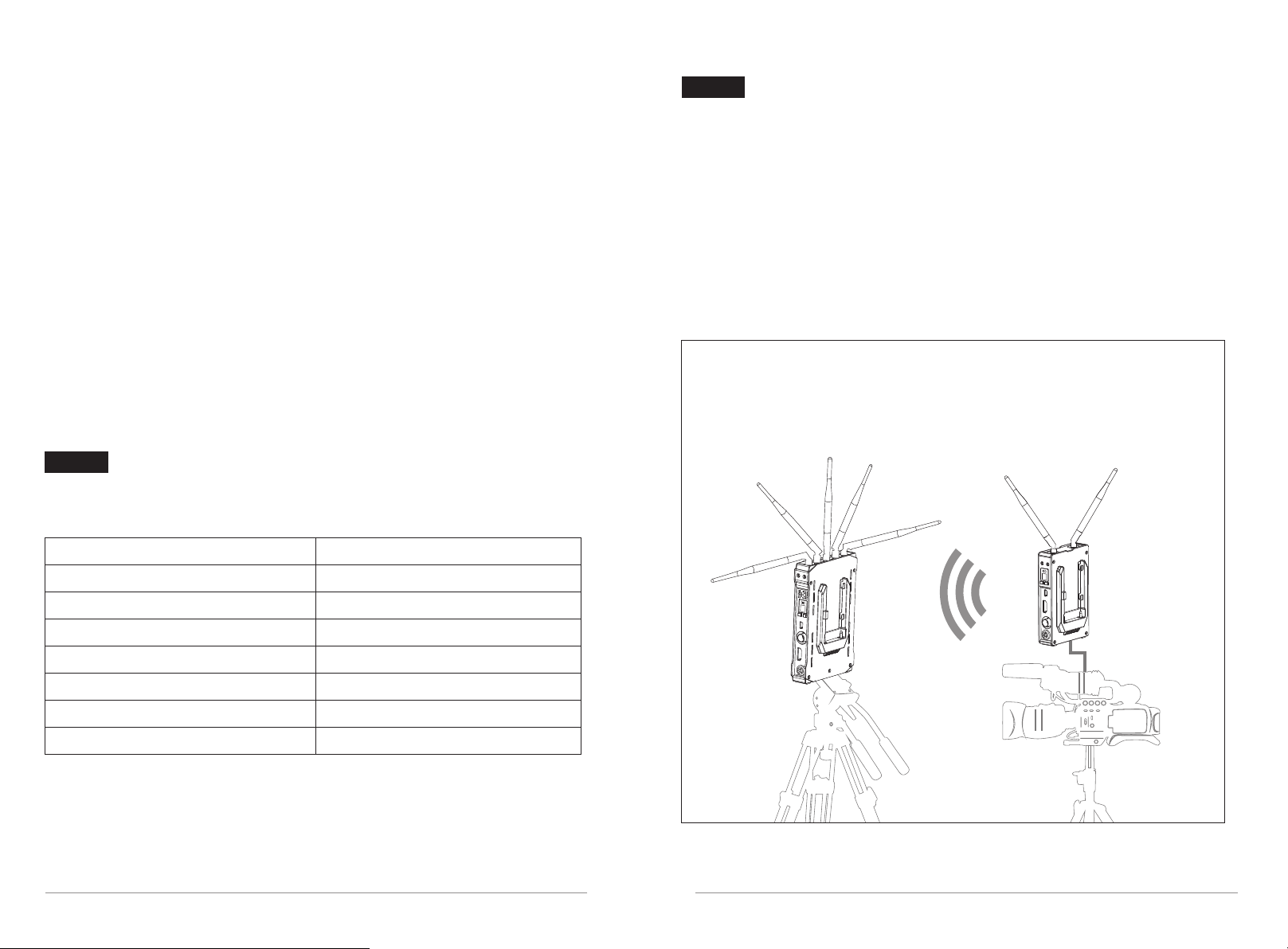
Receiver
Application Recommendations
LED Digits Display: Channel 1 ~ 9, A , b
Video Indicator: HDMI and SDI outputs are enabled together,
there are two status of the indicator
1:Red and Yellow light together: RX receives the signal from TX normally,
and HDMI and SDI outputs are working together
2:No light: No output signals via HDMI and SDI por ts
Power Indicator: Flash slowly when the network is not connected.
Light on normally when the network is connected.
Normal/Enhanced Anti-inter ference Mode Indicator :
Decimal point light is off : normal mode
Decimal point light flashes slowly: enhanced anti-interference mode
Support Full PSF resolution
Support Full PSF resolution
25PSF in = 25 PSF out
29.97PSF=29.97PSF out
23.98P in=23.98P out
24P in=24P out
Application Recommendations
In order to reach the best performance of wireless transmission,
we recommend to meet the requirements as follows:
1. The ver tical height of TX and RX should be same and more than 1.5m
2. TX and Rx are working under the condition of line of sight distance
3. Plane of TX antennas toward plane of RX antennas face-to-face
1.Recommended Installation Method under Ideal Position
Make recei ver to stand vertically; a djust a ntennas to a f an-sh aped arran gemen t;
Make trans mitter to st and ver ti cally; adj ust ant ennas to 90° a ngle in t he same plane.
30PSF in = 30PSF out
50i in = 50i out
59.94i in = 59.94i out
60i in = 60i out
25P in=25P out
29.97P in=29.97P out
30P in=30P out
TX:7051RX:3051
1615
Page 11
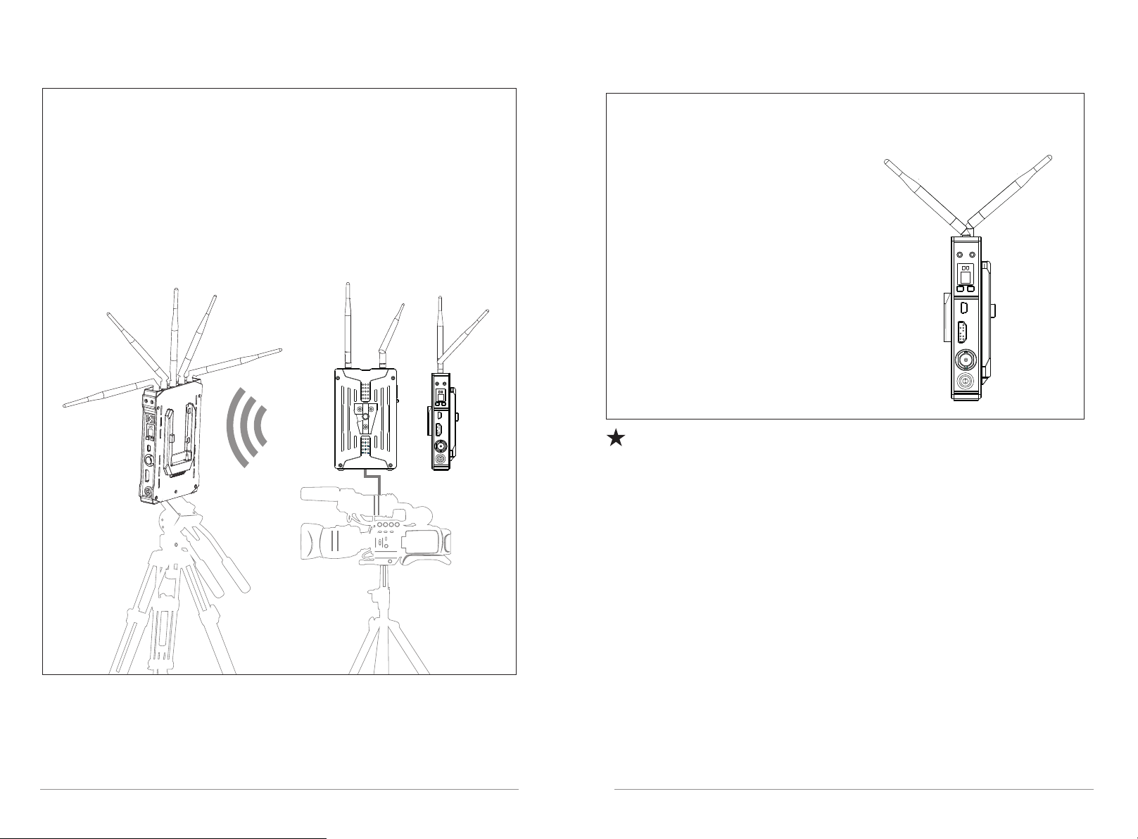
2.Recommended Installation Method under
Non-ideal Position
When the front side of the transmitter is not able to face to the receiver,
Please make receiver to stand ver tically; adjust antennas to a fan-shaped arrangement;
Make trans mitter to st and ver ti cally; adj ust the r ight si de of t he 2 tran smitter
anten nas towards bac kside b y 45°.
Antenna Pattern 2:
Right side 45° angle
rotation towards backside
TX:7051RX:3051
3. Recommended Installation Method
under Non-ideal Position
When the front side of the transmitter is not able
to face to the receiver, please try to adjust the
direction of transmitter antennas to make sure
that the formative fan-shaped arrangement
can face to the receiver for best signal transmission.
As shown in the right figure:
Because TX and RX are working on ISM band, wireless transmission
performance is relevant with level of interference intensity. If transmission
performance declines, we recommend to switch the wireless channel of
TX and RX simultaneously for improvement of transmission performance
1817
Page 12
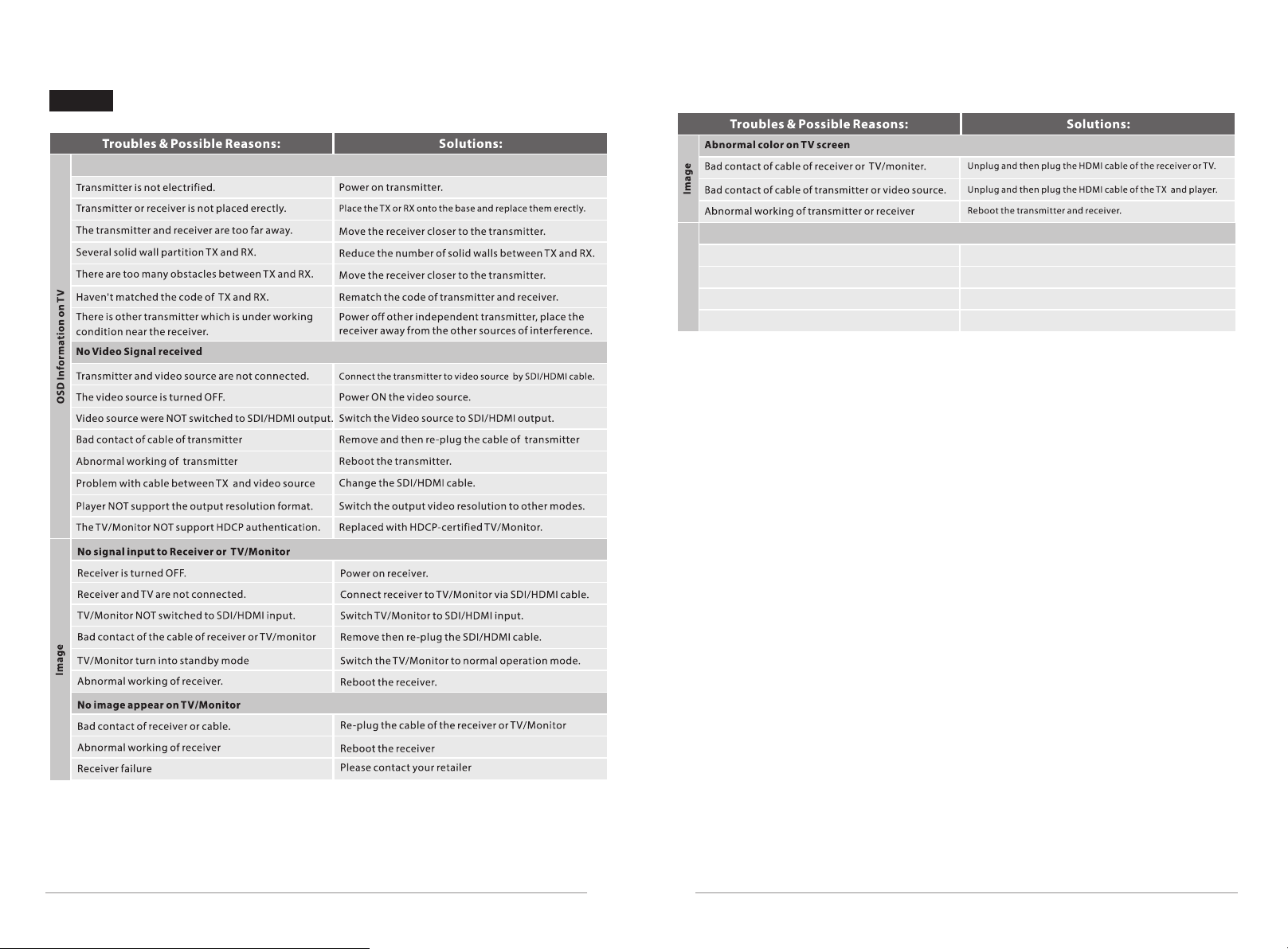
Trouble shooting
Display“Link Connecting”
Image displayed,No audio
Video sourc e mut e
Volu me to o low
Audio format not suppor ted
Something wron g wit h tra nsm itt er/ r ece ive r
Audio
*For more q uestions, p lease conta ct the distri butor or us.
Turn o n the a udi o of video sourc e
Turn u p the a udi o of video sourc e
Swi tch t he fo rma t of video source output
Res tar t the transmission kit
19 20
Page 13
21
 Loading...